1
Andrews Products, Inc.
WARNING!!
CONVERSION CAMS
Will NOT FIT 2007
or LATER ENGINES!
431 Kingston Ct.
Mt. Prospect, IL USA 60056
847-759-0190 (ph)
847-759-0848 (fx)
www.andrewsproducts.com
Installation Instructions: Conversion cams:
Roller Chain Drive to '99-'06 Twin 88 engines
We recommend that you refer to a current '06 Dyna
or later factory service manual and follow factory
procedures for camshaft removal and replacement.
1.
2.
3.
Andrews Products conversion cams operate with 2006
Dyna or 2007 roller cam chain drives and use stock
size lobe base circles. Therefore, unless you have
modified the cylinder heads, the original stock pushrods will be the correct lengths. If the original pushrods
will be reinstalled, removing the fuel tank(s) and rocker
boxes will be necessary. Mark the pushrods so they
can be replaced in their original locations since not all
stock pushrods are the same length.
To save installation time by NOT removing fuel tanks
and rocker boxes, the stock pushrods can be cut with
bolt cutters and then removed in two pieces. EZ-install
pushrods can then be installed. They are available in
aluminum or chrome moly steel. Andrews Products part
numbers for EZ-install pushrods are: 292188 for
aluminum and 292088 for steel pushrods.
Remove 10 screws holding outer cam cover. When this
cover is reinstalled, there is a specific tightening
sequence and torque rating for all 10 screws. VERY
IMPORTANT: Overtightening cover screws can cause
aluminum engine case threads to strip.
4.
Before proceeding further, put the transmission in 4th
or 5th gear. Remove both spark plugs so there will be
no resistance from compression pressure. Now turn the
rear wheel and align camshaft timing marks. This will
simplify installation of new cams.
5.
Remove the crankshaft sprocket retaining bolt and the
rear camshaft sprocket retaining bolt. Both the crankshaft sprocket and the rear cam drive sprocket can now
be removed. They will be replaced with new sprockets
for roller chain cam drive system.
6.
Remove the original cams and cam support plate. All
four oil pump retaining bolts must also be loosened to
permit correct oil pump rotor alignment at the time of
reassembly after the cam support plate is in place with
the new camshafts. The old cam support plate will be
replaced with the new assembly.
7.
Converting 1999-2006 silent chain cam drives to the
2007 style roller chains requires new HD parts. Also
required are two new Andrews conversion camshafts.
Andrews Products conversion cam kits include ALL
of the required parts. Part numbers listed, top of page.
WARNING!!
CONVERSION CAMS
Will NOT FIT 2007
or LATER ENGINES!
Conversion cam kits
Part numbers and years:
1999-2001 ............................... 288999
2002-2006 ............................... 288902
8.
A complete listing of required parts appears below.
9.
"N" series camshafts from Andrews Products must be
used for fitting roller chains to earlier engines. Series
"N" cams are similar to 2006 Andrews Dyna cams
except that the inner bearing journals are .875 instead
of 1.000. Roller chain conversions for '99-'06 engines
require .875 diameter inner camshaft journals to fit
right engine cases.
10. The new conversion cams, inner chains and the new
'06 type support plate can now be assembled as
described in the '06 Dyna HD service manual.
11. Again referring to a factory parts manual, the front cam
thrust washer should be 0.100 thick. Figure 2 on page
3 shows the .100 thrust washer assembled on the
front camshaft with proper end play specified.
12. With new camshafts in place, the new cam support
plate assembly can be reinstalled back into the
engine.
Some HD parts are required for conversion cam installation. All of
these parts are available as complete kits from Andrews. See top of
this page for Andrews part numbers for complete cam kits.
HD Part#
26037-06
25355-06
4741A
11461
25683-06
39969-06
4740A
25675-06
39968-06
942
25729-06
25731-06
25734-06
25736-06
25737-06
25738-06
25673-06
25244-99A
25728-06
216015
Description
See photo on page 3
Oil pump assembly
Cam support plate assembly
Cam Support plate mounting screws; (10 pcs req'd.)
Retaining ring (for front cam)
Inner roller chain
Inner chain tensioner
Inner chain tensioner mounting screws; (2 pcs req'd.)
Outer roller chain
Outer chain tensioner
Outer chain tensioner mounting screws; (2 pcs req'd.)
Spacer (.100 for cam alignment; use as required)
Spacer (.110 for cam alignment; use as required)
Spacer (.120 for cam alignment; use as required)
Spacer (.130 for cam alignment; use as required)
Spacer (.140 for cam alignment; use as required)
Spacer (.150 for cam alignment; use as required)
Crankshaft pinion shaft sprocket (17 teeth)
Outer cover gasket
Stock rear cam sprocket (34 teeth) (2002-'06 only)
Use of stock '06 sprockets on '99, '00 or 2001 conversion
cam installations will result in engine alarm light always ON!
Following part MUST be used with all '99, '00, '01 engines)!
Andrews rear cam sprocket part number (34 teeth)
Some of the screws listed above are the same
as in earlier engines and they can used again.
WARNING! Conversion cams will not fit '06 Dynas or 2007 and later engines!
1
13. After a trial assembly, alignment of crankshaft sprocket
and cam sprocket positions must be checked and
adjusted with shims if necessary. See factory manual
for proper procedure. Make sure all timing marks are
aligned before proceeding!
14. Installing the new 34T sprocket requires using either
the original sprocket spacer or a new spacer from HD if
the original is not the correct thickness for your engine.
HD makes shims and spacer washers in 6 different
thicknesses.
HD Part numbers are:
25729-06
0.100 inches
25731-06
0.110 inches
25734-06
0.120 inches
25736-06
0.130 inches
25737-06
0.140 inches
25738-06
0.150 inches
VERY important: both cams must have as a minimum:
.008-.010 end play in cam support plate!
See figures 1 & 2 below:
15. When installing sprocket retaining bolts, use Loctite
retaining compound to secure the bolt threads. Bolt
torque should not exceed 25 ft-lbs for 5/16 x 18 bolts.
Bolt torque for splined rear camshafts (3/8 x 24 bolt)
should not exceed 35 ft-lbs. Please note that both cam
retaining bolts must be rated grade 8. Grade 8 bolts
have a 6 pointed star symbol on the top of the bolt
heads.
17. EZ-install pushrods use 2 long ( exhaust), and 2 short
(intake) rods. To install, adjust pushrod to shortest
length, then position in engine, rocker arm end first.
Swing the lower end into lifter. Lengthen pushrod
adjuster until all free play is gone. Adjust pushrod 3.5-4
full turns longer (21-24 flats) and tighten locknut. Wait
until hydraulic unit bleeds down and repeat procedure
on next pushrod. When adjusting pushrods, make sure
that cam lobe for that pushrod is on low lift point. Lifter
housing covers can be temporarily removed to gain
another 1/4 inch of clearance. Short pushrod cover
tubes are available from HD. Short pushrod cover
tubes make the pushrod adjustment easier. Part
numbers are: 17938-83 and 17634-99. You will need 4
of each part number to install a complete set.
18. For engines with stock pistons and stock heads, 12N**,
21N, 26N, 31N, and 37N cams should be able to bolt in
without head work. 50N cams need piston to valve
clearances and valve to valve clearances checked.
50N, 54N and 55N cams need .620 minimum valve
travel and .060 minimum piston to valve clearance.
With Andrews Products high lift steel collars (part#
293115; includes 4 pieces), setting valve spring travel
for either of these two higher lift cams will be easier.
Andrews collars fit 1999-2003, Heads for 2004-2006
engines use beehive type springs.
**12N cams are similar in specifications and performance to stock 88 cams.
16. Reinstall the outer cam cover with the 10 cover bolts.
Cover bolts must be tightened to a torque specification
of 90-120 in-lbs. The service manual shows the correct
tightening sequence.
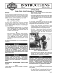
Figure 1: Rear camshaft
Figure 2: Front camshaft
Rear Andrews cams manufactured after July, '06, do not use an
"O" ring to align the spacer washer. To adjust alignment of 34T
rear cam sprocket and 17T crankshaft sprocket, HD spacer
washers are available in 6 different sizes. Cam end play
should be .008/.012 minimum, as shown.
HD service manuals for '06 Dyna and all later twin cam
engines specify a .100 thick thrust washer on the outside
end of the front camshaft. Front cam end play should also
be .008/.012 minimum.
2
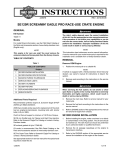
Conversion parts
Andrews Products: Roller Chain Conversion Camshafts
Andrews#
Grind
Timing*
Duration*
Lift
Springs
TDC Lift
Spring Travel
--------
HD Dyna
('06 fuel inj)
02/34
41/-02
216
219
.473
.473
Stock
-
.087
.110
Stock
Stock
216812
12N
02/34
40/02
216
220
.489
.489
Stock
-
.091
.095
Stock
Stock
216821
21N
10/30
40/08
220
228
.498
.498
Stock
-
.134
.121
Stock
Stock
216826
26N
11/35
41/09
226
230
.490
.490
Stock
-
.138
.120
Stock
Stock
216831
31N
10/46
52/08
236
240
.510
.510
Stock
-
.131
.120
Stock
Stock
216837
37N
18/38
46/14
236
240
.510
.510
Stock
-
.174
.148
Stock
Stock
216854
54N
16/42
43/15
238
238
.555
.555
Hi-lift
-
.165
.158
Stock
Stock
216850
50N
20/48
54/18
248
252
.510
.510
Stock
-
.184
.168
Stock
Stock
216855
55N
22/46
52/20
248
252
.550
.550
Hi-lift
-
.197
.181
.620
.620
216867
67N
24/48
58/22
252
260
.570
.570
Hi-lift
-
.209
.187
.620
.620
*Timing and duration listed for .053 cam lift
IMPORTANT NOTE for 1999 engines.
If you are converting a 1999 engine to new
roller chains, please read the following page!
Cams_conversion_chain-01.pmd (1-15-09)
3
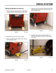
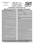
IMPORTANT NOTE for 1999 twin cam engines:
When converting a 1999 engine to new roller chain cams, please note the following!
This page only applies to early 1999 engines. To identify the engine as an early
1999, examine the cam support plate as
illustrated in the circled area. (figure 1)
If the part number on the left front face of
the cam support plate reads: H-D 25245-99,
the engine is an early 1999.
The part number used on later 1999 engines is: 25245-00. If your engine is a late
'99 (or later), disregard the rest of this page,
it is not relevant.
figure 1
Early '99 engines have a different oil supply
system than later engines. Note the circled
area on the photo (inside engine case to the
left of the pinion shaft). (figure 2)
Early '99 engines do not have the oil boss
shown circled in the photo. For early 99's, it
will be necessary to block a matching oil
port on the 2007 cam support plate. See
figure 3 below.
figure 2
For 2007 cam support plates to operate
properly with early '99 engines, the circled
hole in photo must be permanently blocked.
A 1/4 x 20 bottoming tap can be used to cut
threads. A self-locking socket head set
screw will then seal the port. The existing
hole is correctly sized for the tap. Do not
drill it larger! We will send, no charge, set
screws (1/4 x 20 x 1/2) if you call us.
After tapping new threads in the support
plate, make sure to clean out all metal chips
before installing the set screw.
figure3
4