1
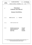
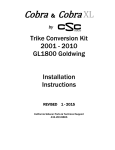
Created by JT
INSTRUCTIONS FOR INSTALLING GALFER BRAKE LINE KIT
2001~ 2006 HONDA GOLDWING 1800A
310 Irving Dr Oxnard, CA 93033
Galfer Tech: 1-800-685-6633
[email protected]
Thank you for purchasing Galfer lines. In order to get the maximum performance and
enjoyment out of your Galfer lines, please read the instructions thoroughly before you begin
installation.
Must have items:
Torque wrench, line wrenches, a commercial available vacuum/pressure bleeder for brake
systems, replacement DOT 4 brake fluid ( two 500cc bottles needed ), shop towels, and a
general assortment of metric tools.
NOTE: THIS IS A TIME CONSUMING TASK REQUIRING KNOWLEDGE OF THE
MOTORCYCLE’S BRAKE SYSTEM, MECHANICAL ABILITY, AND THE USE AND
OPERATION OF SPECIALIZED TOOLS. HAVING THE FACTORY HONDA SERVICE
MANUAL FOR THIS MOTORCYCLE IS NEEDED.
PREP THE MOTORCYCLE FOR THIS JOB
1
Created by JT
(Fig:MG0033)
Park the
motorcycle on
the center stand
in a well-lit shop
Note: It is
absolutely
necessary to
remove the fuel
tank and body
panels (see
factory manual).
Brake fluid is
VERY
CORROSIVE
TO PAINT.
MG0033
Remove the
lower fairing left
and right rear sides, fuel tank, front fender, seat, and black plastic inner fairing front parts,
battery cover, battery, and rear master cylinder cover according to the service manual.
(Fig.MG0033 &
MG0035)
After safely storing the
body panels and fuel
tank, remove wind
shield, (brake fluid,
even a drop, will
permanently mark any
clear plastic), cover the
dash and all gauges
with a towel.
MG0035
DRAINING THE BRAKE FLUID FROM THE SYSTEMS.
2
Created by JT
Note:
• A contaminated brake disc or pad reduces stopping power. Discard contaminated
disc with a high quality brake degreasing agent.
• Do not allow foreign material to enter the system when filling the reservoir.
• Avoid spilling fluid on painted, plastic or rubber parts. Place a rag over these parts
whenever the system is serviced.
• Use only DOT 4 brake fluidfrom a sealed container.
• Do not mix different types of fluid. They are not compatible.
• Once the hydraulic system has been opened, or if the brake feels spongy, the system
must be bled.
• When using a commercially available brake bleeder, follow the manufacture’s
operating instructions.
Remove front fender and fender covers.
Support the motorcycle on its center stand.
Turn the handlebar to the left until the front
master cylinder reservoir is level before
removing the reservoir cap. Remove the
screws, reservoir cap, set plate and diaphragm.
3
Created by JT
Connect a
commercially
available brake
bleeder to the bleed
valve of the front
caliper at the
position as shown.
Loosen the bleed
valve and pump the
brake bleeder until
no more fluid flows
out of the bleed
valve. Tighten the
bleed valve.
Perform the above
procedure at the
other front caliper.
4
Created by JT
Remove the following:
- Right engine side cover.
- Front fender A and fender covers
Support the motorcycle on its center
stand.
Remove the rear master cylinder
reservoir cap. As shown on the right.
Connect a commercially
available brake bleeder to the
bleed valve of the front caliper at
the position as shown. Loosen
the bleed valve and pump the
brake bleeder until no more fluid
flows out of the bleed valve.
Perform the above procedure at each
remaining valve of the brake pedal
brake line.
5
Created by JT
BEGIN INSTALLATION OF NEW BRAKE LINE SYSTEM.
We recommend replacing one line at a time.
Note: Remove brake fluid from the system. (Factory service manual 15-6,7, and 8)
FRONT MASTER CYLINDER
1. Install Line #1 into front master cylinder (MG0008), following stock routing under handle
bar cover, across top triple clamp retainers, down to right OEM tubing w/ brass olive. Secure
to right front brake hose stay w/ cable tie (MG0009, MG0021)
(Fig: MG0008)
Starting from the Front
Master Cylinder (Line# 1)
route to very right top
OEM tubing.
(Fig: MG0009)
Triple tree area.
(Line# 1) Connected to
very right top hard pipe
with brass olive as shown
below.
Note: Use brass olive to
OEM tube.
6
Created by JT
FRONT BRAKE HOSE ASSEMBLY AND ROUTING
Note: Remove “wind protector” (13-42 factory manual), remove brake hose clamps
from brake hose clamp stay.
RIGHT HAND SIDE
1) Install Line #2 on the (MG0021) into OEM tubing, with brass olive.
Secure to right front brake hose stay with cable tie. Install lower end of Line #2 to top
banjo bolt hole of delay valve (MG0025)
2) Install Line #3 into OEM tubing with brass olive (MG0027). Install lower end Line #3
into new Galfer T-block (MG0025), use mounting bolt from stock block.
3) Install Line #7 into delay valve (MG0030) and lay over the top of the tire.
4) Install Line #6 into new Galfer T-block (MG0025) and lay over the top of the tire.
5) Install Line #8 into new Galfer T-block (MG0025). Install lower end line #8 into top
banjo bolt hole of right caliper.
6) Install line #5 into lower banjo bolt hole of delay valve to the lower bolt hole of the
right caliper.
LEFT HAND SIDE
1) Install Line #4 (MG0027) into OEM tubing with brass olive. Secure to left front brake
hose stay with cable ties. Install lower end Line #4 with double banjo bleeder bolt to
top of Line #9, into top of second master cylinder (MG0028).
2) Install Line #10 on top of Line #7 with double banjo bolt into the front of the second
master cylinder (MG0031). Bottom Line #10 attaches to upper banjo bolt hole of the
left caliper (MG0032).
3) Install Lower end Line#6 to lower banjo bolt hole left caliper (MG0032)
4) Install lower end Line#9 to plunger (MG0029).
(Fig: MG0009 OEM)
Visual look at stock
set up to compare
with (Fig: MG0009,
MG0021, &
MG0027) for line# 1,
2, 3, & 4.
7
Created by JT
(Fig: MG0021)Line#
2 is connected to
lower right hard OEM
tube with brass olive.
Line# 2 goes to right
upper delay valve
banjo hole. Check
with (Fig: MG0009
OEM) for picture
overview.
Note: Use brass olive to
OEM tube.
(Fig: MG0027)
Line# 3 goes to upper
Galfer T-block hole
from the OEM tube
with brass olive.
Line# 4 is the farthest
left line connected the
OEM tube with brass
olive. Line# 4 goes to
Secondary Master
Cylinder on a Double
banjo with Line# 9.
Check with (Fig:
MG0009 OEM) for
picture overview.
Note: Use brass olive to
OEM tube.
8
Created by JT
(Fig: MG0022)
Line# 2 is now
routed right side
and connected to
the upper delay
valve top hole.
Lower Delay
valve hole will
have Line# 5
going to the right
lower caliper hole.
Line# 8 is
connected to the
right upper caliper
hole.
(Fig: MG0023)
Line# 8 is
connected to front
right top caliper
hole, Line# 5
connected to front
right bottom
caliper hole.
9
Created by JT
(Fig: MG0025)
Analyzing front
right back side fork
line routing. Using
a Galfer T-block
replacing OEM
split. Line# 6
connected to Galfer
T-block routed to
left lower caliper
hole. Line# 7 is
behind the T-block
where it is
connected to Delay
valve shooting
towards left fork. Line# 7 goes to Secondary Master Cylinder using a double banjo on the
same double banjo Line# 10 is connected to 2nd Master Cylinder.
(Fig: MG0030)
Picture is showing the
back side of Right
fork. Behind the new
T-block Line# 7 is
Connected to Delay
Valve and routed to
2nd Master Cylinder
(Fig: MG0031)
10
Created by JT
(Fig: MG0031)
Back side of 2nd
Master Cylinder.
Note: Double
banjo connected to
Line# 7 & Line#
10.
(Fig: MG0032)
Left caliper is
shown with Line#
6 connected to
bottom hole from
Galfer’s T-block
(MG0025) see ref.
Line# 10 is
connected to upper
hole from the
backside of the 2nd
Master Cylinder.
11
Created by JT
(Fig: MG0028)
Line# 4 connected on
the top of the 2nd
Master Cylinder,
where it’s connected
to the very left upper
hard tube. Located in
the triple tree. Line#
9 is also connected on
an air free double
banjo where it
connected to the anti
dive.
(Fig# MG0029)
Left front fork Line#
9 is connected to Anti
Dive plunger from the
Secondary Master
Cylinder.
12
Created by JT
(Fig: MG0034 CLOSE)
Front brake line routing and overview line map.
13
Created by JT
INSTALATION OF CLUTCH MASTER CYLINDER LINE
1) Install Line #11 into clutch master cylinder (MG0002), following stock routing under
left handle bar cover, across top triple clamp retainer (MG0009MOD). Route Line #11
down along left side steering (OEM 1) head, down behind rear ABS modulater (OEM
2) across front engine to slave cylinder.
Note: Remove mounting bolt/coolant drain valve, (OEM 3) pull forward and up to access
slave cylinder.
(Fig: MG0002)
Left Top Clutch
Master Cylinder
line# 11 positioned
like shown.
(Fig:
MG0009MOD)
Triple tree area,
Line# 11 is shown
routed left front side
of the bike.
14
Created by JT
(Fig: OEM1)
Following stock routing under
left handle bar cover, across
top triple clamp retainer
(Fig: OEM2)
Route Line #11 down along
left side steering (OEM 1)
head, down behind rear ABS
modulater (OEM 2) across
front engine to slave cylinder.
(Fig: OEM3)
Remove mounting
bolt/coolant drain valve, pull
forward and up to access
slave cylinder.
15
Created by JT
(Fig: MG0003)
Line# 11 shown connected to
clutch slave cylinder. In between
banjo stopper.
(Fig: MG0034)
Completed front brake line. Lines 1~11
should be installed.
16
Created by JT
REAR BRAKE LINE INSTALLATION
Note: Prep motorcycle, follow factory manual to remove fuel tank and right hand saddle bag
(MG0035).
1) Install Line #12 to top of rear master cylinder, (MG0004) routing to OEM tubing, with
brass olive, (MG0005), using stock mounting bracket.
2) Install Line #13 “inside”, Line #14 “outside” with brass olives to OEM tubing
(MG0006). Follow stock line routing (OEM4), (OEM 6) across top of the swing arm,
using OEM hose clamps to the rear caliper.
3) Line #13 mounts to upper banjo bolt hole in rear caliper. Line #14 mounts to lower
banjo bolt hole in rear caliper (MG0007).
Note: Rear wheel speed sensor wire must be secured to brake lines with cable locks, to keep
it out of rear wheel.
(Fig: MG0004)
Right middle Rear
Master Cylinder
banjo position as
shown.
17
Created by JT
(Fig: MG0005)
Line# 12 rear line
from master
connected to OEM
tubing with brass
olive right side
frame under the
seat.
Note: Use brass olive to
OEM tube.
(Fig: OEM 4)
Follow stock line
routing (OEM4),
(OEM 6) across
top of the swing
arm, using OEM
hose clamps to the
rear caliper.
18
Created by JT
(Fig: OEM 6)
Follow stock line
routing (OEM4),
(OEM 6) across
top of the swing
arm, using OEM
hose clamps to the
rear caliper.
(Fig: MG0006)
Line# 13 & 14 are
connected to the
OEM tubing with
brass olives.
Location is
between swing
arm and frame
cross member.
Note: Use brass olive to
OEM tube.
19
Created by JT
(Fig: MG0007)
Line# 13 & 14 are
connected to right
rear caliper.
YOU ARE NOW READY TO FOLLOW…WORD FOR WORD…THE FACTORY
PROCEDURE FOR BLEEDING THE SYSTEM. A COPY OF THE HONDA
PROCEDURE IS INCLUDED WITH THESE DIRECTIONS.
All banjos and Double banjos are torque to 12-15 ft/lbs.
A copy of the factory instructions ( Fig: OEM BLEED) has been included with this
kit on how to properly and safely drain, fill and bleed the brake fluid from the brake
systems. Follow the bottom directions closely and remove the fluid according to the
instructions. Dispose of the old fluid properly--DO NOT REUSE.
8 Parts included in the kit
1.
2.
3.
4.
5.
6.
7.
8.
20
Single Banjo Bolt – 13
Double Banjo Bolt – 1
Air Free Double Banjo Bolt – 1
Crush Washer – 32
Brass Olive – 7
T-Block – 1
SS Lines – 14
Instruction pg – 23
Created by JT
OEM
BLEED
21
Created by JT
Before performing this service, have at LEAST 500cc DOT 4 brake fluid. Feed fluid and
bleed air from the pedal brake line in the following sequence.
(1) Left front caliper upper side bleed valve. (Fig: Principles of Front Brake)
(2) Right front caliper lower side bleed valve (Fig: Principles of Front Brake)
(3) Rear caliper lower side bleed valve (Fig: Principles of Rear Brake)
(4) Anti-dive plunger bleed valve (Fig: Principles of Rear Brake)
(5) Rear caliper upper side bleed valve (Fig: Principles of Rear Brake)
22
Created by JT
(Fig: Location of Brake System)
This is provided as a Legend guide, technical name and location on bike.
23