1
SERVICE MANUAL MARINE ENGINES
06 ELECTRICAL SYSTEM
06 ELECTRICAL SYSTEM
Table of Contents
06.00
06.00.01
General ......................................................................................................... 3
Cable numbers and principal functions .......................................................... 3
06.01
06.01.01
06.01.02
06.01.03
06.01.04
Alternator ..................................................................................................... 4
Adjust poly-V-belt tension ............................................................................. 4
Replace generator......................................................................................... 5
Technical data of alternator .......................................................................... 6
Check alternator (error detection for BOSCH alternator, 4 cyl. engines) .... 14
06.03
06.03.01
Replace starter motor ............................................................................... 16
Check starter ................................................................................................ 17
06.05
06.05.01
06.05.02
06.05.02.01
06.05.02.02
06.05.02.03
06.05.02.04
06.05.03
06.05.03.01
06.05.03.02
06.05.03.03
06.05.03.04
Cables, wiring harness - general ............................................................. 19
Battery cable lengths and cross-sections .................................................... 19
E - box base plate; to eng.no.: 482 17 000 ................................................. 20
Components of E - box ................................................................................ 21
Connection start assist relay K28 ................................................................. 21
Connection relay socket for K24, K26-1, K26-2, and K27............................ 21
Wiring harness; to eng.no.: 482 17 000 ...................................................... 22
E - box base plate; from eng.no.: 482 18 000/682 18 000 + SOLAS ......... 28
Components of E - box ................................................................................ 29
Connection start assist relay K28 and K26-2 ............................................... 29
Connection relay socket for K24, K26-1, and K27 ....................................... 29
Wiring harness; from eng.no.: 482 18 000/682 18 000 + SOLAS .............. 30
06.06
06.06.01
06.06.02
06.06.03
06.06.04
06.06.05
Electronics - general .................................................................................. 36
Electronic Engine Management System ..................................................... 36
Diagnostic system ....................................................................................... 37
Reading error codes .................................................................................... 38
Idication & cancellation of memorized sensor and circuit faults .................. 39
Principle failure code list ............................................................................. 40
06.06.06
Replace fuses ............................................................................................. 42
06.06.07
06.06.08
06.06.09
Connection J 1 ............................................................................................. 43
Connection A 5 and X5 ................................................................................ 44
Fitting main connector "J1" properly ............................................................ 45
06.07
06.07.01
06.07.02
06.07.03
06.07.04
06.07.05
Instrument panel .......................................................................................
Chart - operating status normal operation ...................................................
Chart - error indication on instrument panel ................................................
Instrument panel (for SOLAS only) .............................................................
Chart - operating status normal operation (for SOLAS only) ......................
Chart - error indication on instrument panel (for SOLAS only) ....................
06.07.10
6 Cyl. Wiring harness instrument panel (if alternator "PRESTOLITE" is
used - old version)........................................................................................ 58
Description - Wiring harness instrument panels 4/6 cyl. marine engines
(current version) ........................................................................................... 62
06.07.11
Z001019/0_6_July 2008
46
47
48
52
53
54
Page ELECTRICAL SYSTEM - 1
06 ELECTRICAL SYSTEM
SERVICE MANUAL MARINE ENGINES
06.07.13
Adjust instruments ....................................................................................... 68
06.07.13.01 Tachometer with running-time meter ........................................................... 68
06.07.14
06.07.14.01
06.07.14.02
06.07.14.03
06.07.14.04
Replace instruments .................................................................................... 70
General notes on safety ............................................................................... 70
Audible warner, H22 ..................................................................................... 72
Circuit diagram voltmeter (optional) ............................................................. 73
Circuit diagram oil pressure gauge (optional, sensor B19-gauge P2) .......... 73
06.08.01
06.08.02
06.08.03
Potentiometer accelerator, B13 ................................................................ 74
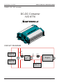
Voltage regulator 24V - 12V equalizer ......................................................... 75
DC - DC converter ........................................................................................ 76
06.10
06.10.01
06.10.02
06.10.03
Sender, sensor .......................................................................................... 78
Component configuration 4 cyl. engine ........................................................ 78
Component configuration 6 cyl. engine ........................................................ 80
Calibration of rack position ........................................................................... 82
06.10.04
06.10.04.01
06.10.04.02
06.10.04.03
06.10.04.04
06.10.04.05
06.10.04.06
06.10.04.07
06.10.05
06.10.05.01
06.10.05.02
06.10.05.03
06.10.05.04
06.10.05.05
06.10.05.06
06.10.05.07
06.10.05.08
Replace sender, sensor ............................................................................... 83
Sensor exhaust gas temperature B17 .......................................................... 83
Sensor engine temperature B16 .................................................................. 83
Sensor engine speed B15 ............................................................................ 83
Sensor boost pressure B12.......................................................................... 83
Sensor rack position feedback B14.............................................................. 84
Sensor oil pressure B18 ............................................................................... 84
Potentiometer accelerator B13..................................................................... 84
Check sensors and switches ........................................................................ 85
Check rack position feedback sensor B14 (= connector X14) ..................... 85
Check throttle potentiometer B13 (accelerator) (= connector X13) .............. 87
Check boost pressure sensor, B12 .............................................................. 88
Check speed sensor B15 and/or wiring ....................................................... 89
Check oil pressure sensor B18 and/or wiring ............................................... 90
Check oil pressure sensor "VDO-instrument" (option B19) .......................... 91
Check coolant temperature sensor, B16 ...................................................... 92
Check audible warner .................................................................................. 93
06.12
06.12.01
Battery ........................................................................................................ 94
Battery ......................................................................................................... 94
Page ELECTRICAL SYSTEM - 2
Z001019/0_6_July 2008
SERVICE MANUAL MARINE ENGINES
06.00
06 ELECTRICAL SYSTEM
GENERAL
Wiring
For the STEYR Marine Engines wiring and plug connections have been defined according
to standard DIN 72 552.
In case of necessary repair of a cable connection, take special care that cable quality, isolation,
crimping, strand end soldering of cable sockets as well as protective varnish isolation and/or
connector locks meet the respective requirements.
Tools for crimp connections to be found in tool catalog P/N Z001002/0 "Level 4".
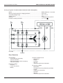
06.00.01 Cable numbers / principal functions:
15000-xx
ignition - positive
(from ignition switch)
31100-xx
Do not connect earth for sensors
with battery-negative!
15012-xx
+12 volt via main relay
and control unit A5
601xx-01
Sensor signal to control unit
A5 and/or instruments.
15100-xx
+5 volt supply voltage for sensors
606xx-01
30000-xx
battery-positive (not secured)
Output from control unit A5
to display system (tachometer,
temperature display, ...)
30012-xx
battery-positive (secured)
31000-xx
battery-negative (GND)
Z001019/0_6_July 2008
Page ELECTRICAL SYSTEM - 3
06 ELECTRICAL SYSTEM
06.01
SERVICE MANUAL MARINE ENGINES
ALTERNATOR
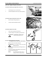
06.01.01 Adjust poly-V-belt tension
For 4 cyl. engines only
Automatic initial tension of belt tension
through spring-loaded tightener. (ill.1 and ill.2)
1
01.01 ill.1
1
01.01 ill.2
For 6 cyl. engines only
As to tension of V-belt for alternator,
refer to chapter 05.07.01 - 02
Page ELECTRICAL SYSTEM - 4
Z001019/0_6_July 2008
SERVICE MANUAL MARINE ENGINES
06 ELECTRICAL SYSTEM
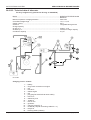
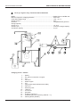
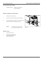
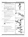
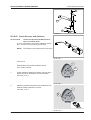
06.01.02 Replace alternator
Preparatory work: turn off engine, disconnect battery
1
Disconnect two cables (ill. 1/pos.1+2).
2
1
2
Remove belt.
3
Loosen screws (ill.2/pos.1+2), remove alternator.
01.02 ill.1
NOTE:
Assembly is done in reverse order.
1
2
For 4 cyl. engines only
Connections
acc. illustration 3:
01.02 ill.2
ill.3/1
B+
battery
ill.3/2
D+
charging control (L1)
ill.3/3
DF
D-field (rotor winding)
ill.3/4
D+
on governor
3
4
2
1
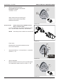
For 4 cyl engines only
Governor
acc. illustration 4:
ill.4/1
B-
ill.4/2
DF
ill.4/3
D+
ill.4/4
D+
01.02 ill.3
1
2
3
4
01.02 ill.4
Z001019/0_6_July 2008
Page ELECTRICAL SYSTEM - 5
06 ELECTRICAL SYSTEM
SERVICE MANUAL MARINE ENGINES
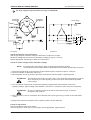
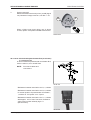
06.01.03 Technical data of alternator
For 6 cyl. engines only (old version till eng. no. 68224418)
Model .................................................................................................... PRESTOLITE LEECE-Neville
.............................................................................................................. 8RG2043
Minimum speed for voltage generation ................................................. 580 1/min
Controlled voltage range ....................................................................... 13,9 - 14,2 V
Output current ....................................................................................... 90 A
Governor ............................................................................................... integrated base governor
Charge capacity
at 750 r.p.m. .......................................................................................... approx. 34 A
at 2500 r.p.m ......................................................................................... maximum charge capacity
Condensor capacity .............................................................................. 2,2 µF
01.03 ill.1
Charging circuit - scheme
1 ...... battery
2 ..... Z2, ground connection on engine
3 ..... red
4 ..... fuse 50 A
5 ..... starter engine
6 ..... red
7 ..... plug (engine electrics/instrument cable)
8 ..... fuse 10 A
9 ..... starter key lock
10 ..... 15000-xx
11 ..... red 16 mm²
12 ..... generator
13 ..... charging controll (L1)
14 ..... 61000-02 (18-pole connecting cable No.: 11)
15 ..... relay K10
16 ..... blocking diode (1N4007)
Page ELECTRICAL SYSTEM - 6
Z001019/0_6_July 2008
SERVICE MANUAL MARINE ENGINES
06 ELECTRICAL SYSTEM
For 6 cyl. engines only (old version till eng. no. 68224418)
circuit diagr.:
Governor
01.03 ill.3
01.03 ill.2
Check of alternator and connections:
With engine stopped, measure voltage on alternator (+output and -output).
Measured voltage may be lower than the battery voltage by (up to) 1 volt only.
Where appropriate, test wiring of cables and connections.
Check of control voltage and/or alternator voltage:
NOTE:
For these works, the battery's state of charge should be 95% at least.
Check tension of belt on alternator drive and make sure that cables are perfectly connected.
1. Disconnect all electrical consuming devices and adjust engine to a speed of approx. 1000 rpm.
2. Connect voltmeter to alternator output "B +".
3. Remove plastic screw on governor and apply screw driver with fine blade on adjusting screw.
ATTENTION:
The adjusting screw has a min./max. stop. There is danger to damage the governor
when turning by force the adjusting screw so far that it overtravels the specified
control range.
4. Turn screwdriver clockwise to increase the operating voltage and/or anticlockwise to lower the
operating voltage. Adjust voltage range between 14,0 and 14,2 volt (28,0 to 28,4 volt for 24-volt plants).
ATTENTION:
Do not turn adjusting screw so far that it overtravels the stop, to prevent
damages to the governor.
5. After adjustment, remove screwdriver and voltmeter and lock the governor by means of removed plastic
screw.
If voltage cannot be set to specified value, replace governor and/or alternator.
Check of slip pistons:
Disconnect battery and/or main switch.
Unscrew governor. Clean slip ring and wipers; where appropriate, replace wipers.
Z001019/0_6_July 2008
Page ELECTRICAL SYSTEM - 7
06 ELECTRICAL SYSTEM
SERVICE MANUAL MARINE ENGINES
For 6 cyl.engines / Technical data of alternator 14V / 90A (current version from eng. no. 68224419)
Model .................................................................................................... ISKRA-AAK5550-11.203.329
Minimum engine speed for voltage generation ..................................... 550 1/min
Controlled voltage range ....................................................................... 14,1 - 14,5 V
Output current ....................................................................................... 90 A
Governor ............................................................................................... integratedl base governor
Excitation winding resistance ................................................................ 2,7 / +0,27
01.03 ill.4
Error Detection
Check battery:
- All connections (terminals)
- Acid concentration
- Filling level (check, refill if necessary)
- Carry out load test
Excessive voltage:
- Governor
- Loose connections
- Battery
Page ELECTRICAL SYSTEM - 8
Charging voltage too low:
- Belt tension
- Output
- Governor
- Slip ring
- Internal components of alternator
No charging voltage:
- Belt tension
- Charging control lamp defective (12V/2W)
- Output
- Cables and connections
- Governor
- Slip ring
- Internal components of alternator
Z001019/0_6_July 2008
SERVICE MANUAL MARINE ENGINES
06 ELECTRICAL SYSTEM
For 6 cyl. engines / Technical data of alternator 28V / 80A (Option)
Model .................................................................................................... ISKRA-AAN5161- 11.203.220
Minimum engine speed for voltage generation ..................................... 550 1/min
Controlled voltage range ....................................................................... 28,1 - 28,7 V
Output current ....................................................................................... 80 A
Governor ............................................................................................... integratedl base governor
Excitation winding resistance ................................................................ 7,9 / +0,79
01.03 ill.5
Error Detection
Check battery:
- All connections (terminals)
- Acid concentration
- Filling level (check, refill if necessary)
- Carry out load test
Excessive voltage:
- Governor
- Loose connections
- Battery
Z001019/0_6_July 2008
Charging voltage too low:
- Belt tension
- Output
- Governor
- Slip ring
- Internal components of alternator
No charging voltage:
- Belt tension
- Charging control lamp defective (24V/3W)
- Output
- Cables and connections
- Governor
- Slip ring
- Internal components of alternator
Page ELECTRICAL SYSTEM - 9
06 ELECTRICAL SYSTEM
SERVICE MANUAL MARINE ENGINES
For 6 cyl. engines / Technical data of alternator 28V / 55A (Option)
Model .................................................................................................... ISKRA-AAK5170- 11.201.894
Minimum engine speed for voltage generation ..................................... 550 1/min
Controlled voltage range ....................................................................... 28,0 - 28,4 V
Output current ....................................................................................... 55 A
Governor ............................................................................................... integratedl base governor
Excitation winding resistance ................................................................ 7,9 / +0,79
01.03 ill.6
Error Detection
Check battery:
- All connections (terminals)
- Acid concentration
- Filling level (check, refill if necessary)
- Carry out load test
Excessive voltage:
- Governor
- Loose connections
- Battery
Page ELECTRICAL SYSTEM - 10
Charging voltage too low:
- Belt tension
- Output
- Governor
- Slip ring
- Internal components of alternator
No charging voltage:
- Belt tension
- Charging control lamp defective (24V/3W)
- Output
- Cables and connections
- Governor
- Slip ring
- Internal components of alternator
Z001019/0_6_July 2008
SERVICE MANUAL MARINE ENGINES
06 ELECTRICAL SYSTEM
THIS PAGE IS INTENTIONALLY BLANK
Z001019/0_6_July 2008
Page ELECTRICAL SYSTEM - 11
SERVICE MANUAL MARINE ENGINES
06 ELECTRICAL SYSTEM
For 4 cyl. engines only / Technical data of alternator
Model .................................................................................................... BOSCH No. 6 033GB3 046
Minimum speed for voltage generation ................................................. 550 1/min
Controlled voltage range ....................................................................... 13,9 - 14,7 V
Output current ....................................................................................... 90 A
Governor ............................................................................................... integratedl base governor
Charge capacity
at 750 r.p.m. .......................................................................................... ca. 34 A
at 3000 r.p.m. ........................................................................................ maximum charge capacity
Condensor capacity .............................................................................. 2,2 µF
01.03 ill.7
Charging circuit - scheme
1 ......
2 .....
3 .....
4 .....
5 .....
6 .....
7 .....
8 .....
9 .....
10 .....
11 .....
12 .....
13 .....
14 .....
15 .....
Page ELECTRICAL SYSTEM - 12
battery
Z2, ground connection on engine
red
fuse 50 A
starter engine
red
plug (engine electrics/instrument cable)
fuse 10 A
starter key lock
15000-xx
red 16 mm²
generator
charging control (L1)
61000-02 (18-pole connecting cable Nr.: 11)
blocking diode (1N4007)
Z001019/0_6_July 2008
SERVICE MANUAL MARINE ENGINES
06 ELECTRICAL SYSTEM
For 4 cyl. engines only
Error Detection
Check battery:
- All connections (terminals)
- Acid concentration
- Filling level (check, refill if necessary)
- Carry out load test
Excessive voltage:
- Governor
- Loose connections
- Battery
Charging voltage too low:
- Belt tension
- Output
- Governor
- Slip ring
- Internal components of alternator
No charging voltage:
- Belt tension
- Charging control lamp defective (12V/2W)
- Output
- Cables and connections
- Governor
- Slip ring
- Internal components of alternator
Governor
Alternator - scheme
01.03 ill.8
Z001019/0_6_July 2008
Page ELECTRICAL SYSTEM - 13
SERVICE MANUAL MARINE ENGINES
06 ELECTRICAL SYSTEM
06.01.04 Check alternator (error detection for BOSCH alternator, 4 cyl. engines)
Trouble features
Test procedure
Error and/or Relief
With engine stopped and ignition on,
generator control lamp (L1) not
shining or only slightly.
Tester lamp connected between B+
and D+ on generator ; shining brightly.
Generator control lamp (L1) burned
out and/or disconnection in electric
circuit of generator control lamp (L1)
between term. 15 (No. 15000-xx) and
term. D+ (No. 61000-02) on
generator.
Tester lamp connected between B+
and D+ on generator ; not shining, but
shining brightly when connected
between D+ and ground. Generator
control lamp (L1) does not shine in
both cases.
Short circuit of a positive diode.
Immediately disconnect starter
battery from generator, otherwise
battery may be discharged on state > replace generator.
Tester lamp connected between D+
and ground; tester lamp and
generator control lamp (L1) glowing.
Error, wipers of governor worn out,
oxid film on slip rings, disconnection
of rotor winding -> replace governor
and/or generator.
With both engine stopped and
running, generator lamp (L1)
constantly shines brightly.
With engine stopped, disassemble
attached governor.
Generator control lamp (L1) still
shining brightly.
Generator control lamp (L1)
extinguishes. Install governor again.
Connect ammeter between B+ and
D+ (on generator). Exciting current
is lower than specified (4 amp
+/- 0,4).
Exciting current is higher than
specified (4 amp +/- 0,4).
With engine stopped, generator
control lamp (L1) shines brightly,
with engine running only shines
slightly.
Governor is defective -> replace
governor.
Earth short circuit in the field of
governor and connection DF (see
ill.) of generator, earth short circuit in
rotor winding -> replace generator.
Connect tester lamp between B+ and
D+ of generator.
With engine running, tester lamp
extinguishes.
With engine running, tester lamp
glows.
With engine stopped, install new
governor and start engine again.
Tester lamp between B+ und D+
Tester lamp extinguishes
Tester lamp still glows
Page ELECTRICAL SYSTEM - 14
Earth short circuit in lead betweeen
generator control lamp and terminal
D+ on generator.
Contact resistance in charging circuit
or in conductor to generator control
lamp (L1)
Governor or generator defective.
Disassembled governor was
defective.
Generator is defective -> replace.
Z001019/0_6_July 2008
SERVICE MANUAL MARINE ENGINES
06 ELECTRICAL SYSTEM
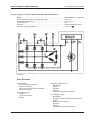
Check rectifier diode
Measuring devices with diode test function will show
the following results:
-
12-V-Lampe
in forward direction: voltage drop from 0.4 to 0.6
volt
in backward direction: reading is "OL".
+
12V
-
a) by means of control lamp
01.04 ill.1
Diode and control lamp are connected in series in
both forward and backward direction in an electric
circuit. Diodes permitting passage in both directions
were mostly exposed to excessive voltages. On the
other hand, diodes with an interruption in forward
direction were mostly destroyed by excessive current
or excessive heating.
ill. 04.1
Lamp burning: diode functional.
Lamp not burning: diode interrupted.
ill. 04.2
Lamp not burning: diode functional,
Lamp burning: diode had short circuit.
12-V-Lampe
+
12V
-
01.04 ill.2
b) by means of ohmmeter
For diode testing, only a simple, battery-powered
ohmmeter may be used.
Measuring bridges are unsuitable, as they indicate
wrong values. Under no circumstances, hand
generators may be used. Their high voltage would
destroy the diodes. A perfect diode shows a resistance
of only a few ohms (0,5 ...10 Ohm) in forward direction,
but several kiloohms (almost) in backward direction.
Z001019/0_6_July 2008
Page ELECTRICAL SYSTEM - 15
SERVICE MANUAL MARINE ENGINES
06 ELECTRICAL SYSTEM
06.03
REPLACE STARTER MOTOR
1
Disconnect battery.
2
Remove cover of E-box. Remove E-box.
3
Loosen terminal +30 (ill.2/pos.1) on magnetic switch
by means of (SW13).
4
Loosen start signal wiring (terminal 50) (ill.2/pos.2)
by means of (SW10).
03.00 ill.1
5
Loosen two hexagon screws (ill.2/pos.3) (SW13) of
starter bracket.
2
6
Loosen two screws (SW8) (ill.2/pos.4), remove starter.
1
4
3
03.00 ill.2
NOTE:
Have starter motor repaired in an
authorized STEYR workshop.
After assembly, coat all electric
supplies with rubber sealing
Z909570/0.
Page ELECTRICAL SYSTEM - 16
Z001019/0_6_July 2008
SERVICE MANUAL MARINE ENGINES
06 ELECTRICAL SYSTEM
06.03.01 Check starter
Trouble features
Cause
Relief
When switching on the starter
(acutation of starter key), starter shaft
not turning or only slowly; starter
pinion not engaging
battery discharged and/or defective
charge battery and/or replace
terminals of starter battery are loose
and/or oxidized, bad ground
connection
clean terminals and tighten, treat with
pole grease, provide ground
connection
earth short circuit of terminals of
starter or carbon brushes
eliminate earth short circuit
carbon brushes not resting on
collector (sticking in guide, are
broken, oily or worn out)
depending on failure, make work
carbon brushes, clean or replace -->
in case of very strong wear, replace
various parts and/or starter
starter key or starter relay K28 and/or
actuating relay on starter defective
replace starter key or relay
voltage drop in lines too large, lines
damaged, line connections loose,
links oxidized
check starter line, eventually replace,
clean links and tighten
starter does not interrupt; starter key,
starter relay (K28), actuating relay
(on starter) defective
short-circuit in wiring (cable No.:
50000-xx connected to +12V)
immediately turn off ignition,
immediately disconnect battery;
check key and/or relay, evenutally
replace; check wiring
in case of longer running time -->
replace starter
starter keeps on running after starter
key was released
Z001019/0_6_July 2008
Page ELECTRICAL SYSTEM - 17
06 ELECTRICAL SYSTEM
SERVICE MANUAL MARINE ENGINES
THIS PAGE IS INTENTIONALLY BLANK
Page ELECTRICAL SYSTEM - 18
Z001019/0_6_July 2008
SERVICE MANUAL MARINE ENGINES
06.05
06 ELECTRICAL SYSTEM
CABLES, WIRING HARNESS - GENERAL
Cable / wiring
In case of necessary repair of a cable connection, take special care that cable quality,
isolation, crimping, strand end soldering of cable sockets as well as protective varnish isolation
and/or connector locks meet the respective requirements.
Tools for crimp connections to be found in tool catalog P/N Z001002/0 "KIT 3".
06. 05. 01. Battery cable lengths and cross-sections
Determine the lenght of the positive cable from the positive pole (+) of the battery to connection No.
30 at the starter.
Total lenght is the sum of cable length of positive cable (+) and earth cable (-).
For example:
positive cable = 3,0 m
ground cable = 2,0 m
----------------------------Total length = 5,0 m ===> cable cross section = 70 mm²
For ground connection, determine corresponding cross-sections as per chart.
For 4 cyl. engines only
starter engine: 2 kW - 12 volt
battery size: 92 AH
length
in m
cable cross-section
in mm²
AWG
0,0 - 4,0
4,1 - 5,0
5,1 - 6,0
50
70
95
0
00
0000
length
in m
cable cross-section
in mm²
AWG
0,0 - 3,0
3,1 - 4,5
4,6 - 5,5
50
70
95
0
00
0000
For 6 cyl. engines only
starter engine: 3 kW - 12 Volt
battery size: 110 AH
In general, take care that battery cable lengths are kept as short as possible.
Z001019/0_6_July 2008
Page ELECTRICAL SYSTEM - 19
06 ELECTRICAL SYSTEM
SERVICE MANUAL MARINE ENGINES
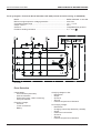
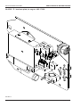
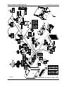
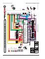
06.05.02 E - box base plate; to eng.no.: 482 17 000
05.02 ill.1
Page ELECTRICAL SYSTEM - 20
Z001019/0_6_July 2008
SERVICE MANUAL MARINE ENGINES
06 ELECTRICAL SYSTEM
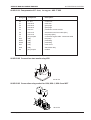
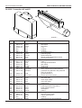
06.05.02.01 Components of E - box; to eng.no.: 482 17 000
Designat.
Component
Description
A5
E - box
control unit
F1
F2
fuse 50 A
fuse 50 A
main fuse
glow plugs
F3
F4
fuse 50 A
fuse 5 A
glow plugs
permanent current module
F5
F6
fuse 10 A
fuse 10 A
switched current for module (K27)
fuel pump (K24)
J1
K24
plug 23-pole
relay
connection engine cable - instrument cable
fuel pump
K26-1
K26-2
relay
realy
preheating
preheating
K27
K28
relay
relay
main circuit
start assist relay
X5
plug 35-pole
module
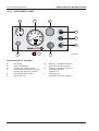
06.05.02.02 Connection start assist relay K28
05.02 ill.2
06.05.02.03 Connection relay socket for K24, K26-1, K26-2 and K27
05.02 ill.3
Z001019/0_6_July 2008
Page ELECTRICAL SYSTEM - 21
SERVICE MANUAL MARINE ENGINES
06 ELECTRICAL SYSTEM
06.05.02.04 Wiring harness; to eng.no.: 482 17 000
Designation
Component
Description
A5
F1
F2
F3
F4
F5
F6
E-box
fuse 50 A
fuse 50 A
fuse 50 A
fuse 5 A
fuse 10 A
fuse 10 A
control unit
main fuse
glow plugs
glow plugs
permanent current modul and K27
switched current for module (K27)
fuel pump (K24)
G1
G2
J1
K24
K26-1
K26-2
K27
K28
M1
M2
R10
X2 (S2)
alternator
battery
23-pole plug
relay
relay
relay
relay
relay
starter
fuel pump
glow pins
2-pole plug
gear switch
X5 (A5)
X12 (B12)
X13 (B13)
X14 (B14)
X15(B15)
X16 B(16)
X17 (B17)
X18 (B18)
X19 (B19)
X20 (Y20)
X22 (B22)
X23
35-pole plug
3-pole plug
5-pole plug
3-pole plug
3-pole plug
2-pole plug
2-pole plug
3-pole plug
1-pole plug
2-pole plug
without stop
6-pole plug
module
boost-pressure sensor
pot. accelerator
pot. rack position
engine speed sensor
engine temperature sensor
exhaust gas temperature sensor
oil pressure sensor
oil pressure gauge (optional)
control solenoid
trim sensor (optional)
diagnosis
Z1
Z2
Z3
Z4
splice spot
splice spot
splice spot
splice spot
earth connection sensor
earth connection (31) on engine
sensor supply +5V
earth connection (31) on E-box plate
to be provided by customer
connection engine cable - instrument cable
fuel pump
preheating - load circuit
preheating - load circuit
main circuit
start
Cable numbers / principal functions:
15000-xx
15012-xx
15100-xx
30000-xx
30012-xx
31000-xx
ignition - positive
(from ignition switch)
+12 volt via main relay
and control unit A5
+5 volt supply voltage for sensors
battery-positive (not secured)
battery-positive (secured)
battery-negative (GND)
Page ELECTRICAL SYSTEM - 22
31100-xx
601xx-01
606xx-01
Do not connect earth for sensors
with battery-negative!
Sensor signal to control unit
A5 and/or instruments.
Output from control unit A5
to display system (tachometer,
temperature display, ...)
Z001019/0_6_July 2008
SERVICE MANUAL MARINE ENGINES
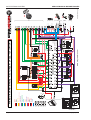
05.02 ill.4
Z001019/0_6_July 2008
06 ELECTRICAL SYSTEM
Wiring harness; to eng.no.: 482 17 000
Page ELECTRICAL SYSTEM - 23
06 ELECTRICAL SYSTEM
Circuit diagram; to eng.no.: 482 17 000
Page ELECTRICAL SYSTEM - 24
SERVICE MANUAL MARINE ENGINES
05.02 ill.5
Z001019/0_6_July 2008
SERVICE MANUAL MARINE ENGINES
06 ELECTRICAL SYSTEM
Line designations from - to
Wiring harness; to eng. no.:48 217 000
cable No.
designation from -->
pin No.
end point --> to
pin No.
15000-01
J1 plug engine / instruments
A
K24 relay fuel pump
86
15000-02
J1 plug engine / instruments
B
K24 relay fuel pump
86
15000-03
X5 control unit (A5)
19
K24 relay fuel pump
86
15012-01
X20 control solenoid(Y20)
1
X5 control unit (A5)
17
15012-02
X5 control unit (A5)
18
K27 main circuit relay
87
15012-03
K27 main circuit relay
87
K26/1 relay preheating
86
15012-04
K26/1 relay preheating
86
K26/2 relay preheating
86
15012-06
X15 speed sensor (B15)
C
K26/2 relay preheating
86
15100-01
X5 control unit (A5)
3
Z3 link (splice)
15100-02
X13 pot. accelerator (B13)
5
Z3 link (splice)
15100-05
X12 boost press. sensor(B12) 3
Z3 link (splice)
15100-06
X14 pot. rack position (B14)
C
Z3 link (splice)
15100-07
X18 oil pressure sensor (B18) B
Z3 link (splice)
17415-01
F2 50A fuse glow plugs
IN
K26/1 relay preheating
87
17415-02
F3 50A fuse glow plugs
IN
K26/2 relay preheating
87
30000-03
K26/1 relay preheating
30
K28 starter relay
30
30000-04
K26/2 relay preheating
30
K28 starter relay
30
30000-05
F1 50A main fuse
IN
starter solenoid
30
30012-01
X5 control unit (A5)
1
F4 fuse control unit
2
30012-02
K27 main circuit relay
86
F4 fuse control unit
2
30012-03
X23 diag
6
K27 main circuit relay
86
30012-04
K27 main circuit relay
30
F5 fuse control unit
2
30012-05
F1 50A main fuse
OUT
F5 fuse control unit
1
30012-06
F1 50A main fuse
OUT
F6 fuse fuel pump
1
30012-07
F1 50A main fuse
OUT
J1 plug engine / instruments
C
30012-08
F1 50A main fuse
OUT
J1 plug engine / instruments
D
30012-09
F5 fuse control unit
1
F4 fuse control unit
Z001019/0_6_July 2008
1
Page ELECTRICAL SYSTEM - 25
SERVICE MANUAL MARINE ENGINES
06 ELECTRICAL SYSTEM
Line designations from - to
Wiring harness; to eng. no.:48 217 000
cable No.
designation from -->
pin No.
end point --> to
pin No.
30055-01
K24 relay fuel pump
30
F6 fuse fuel pump
31000-01
J1 plug engine / instruments
E
Z2 - mass point
31000-02
J1 plug engine / insruments
F
Z2 - mass point
32
31000-03
Z4 earth connection in box
X15 speed sensor (B15)
3
31000-04
fuel pump (M2)
(M5)negat.
Z2 link (splice)
31000-05
X23 diag
1
Z2 link (splice)
31000-06
S4 earth connection in box
31000-07
X2 gear switch(S2)
31000-08
S4 earth connection in box
31100-01
X5 control unit (A5)
20
Z1 link (splice)
31100-02
X13 pot. accelerator (B13)
3
Z1 link (splice)
31100-03
X13 pot. accelerator (B13)
4
Z1 link (splice)
31100-07
X16 ECT (B16)
2
Z1 link (splice)
31100-08
X12 MAP (B12)
2
Z1 link (splice)
31100-09
X14 RACK (B14)
A
Z1 link (splice)
31100-10
X18 oil pressure sensor (B18) A
Z1 link (splice)
31100-11
X17 sensor exh.gas temp.(B17) 2
Z1 link (splice)
31409-01
X20 control solenoid (Y20)
2
X5 control unit (A5)
35
31554-01
K24 relay fuel pump
85
X5 control unit (A5)
22
31555-01
K26/1 relay preheating
85
X5 control unit (A5)
7
31555-02
K26/1 relay preheating
85
K26/2 relay preheating
86
31558-01
K27 main circuit relay
85
X5 control unit (A5)
24
31615-01
J1 plug engine / instruments
H
X5 control unit (A5)
6
50000-01
K28 starter relay
87
X5 control unit (A5)
13
50000-02
K28 starter relay
86
J1 plug engine / instruments
S
50000-03
K28 starter relay
Kl.86
J1 plug engine / instruments
T
60110-01
X12 MAP (B12)
1
X5 control unit (A5)
28
Page ELECTRICAL SYSTEM - 26
2
X5 control unit (A5)
2
2
S2 link (splice)
Z2 earth connection engine
Z001019/0_6_July 2008
SERVICE MANUAL MARINE ENGINES
06 ELECTRICAL SYSTEM
Line designations from - to
Wiring harness; to eng. no.:48 217 000
cable No.
designation from -->
pin No.
end point --> to
pin No.
60111-01
pot. accelerator B13
2
X5 control unit (A5)
12
60112-01
X14 RACK (B14)
B
X5 control unit (A5)
11
60113-01
X15 speed sensor (B15)
2
X5 control unit (A5)
33
60114-01
X16 ECT (B16)
1
X5 control unit (A5)
9
60116-01
X13 pot. accelerator (B13)
1
X5 control unit (A5)
30
60117-01
X18 oil pressure sensor (B18) C
X5 control unit (A5)
10
60118-01
X17 sensor exh.gas temp.(B17) 1
X5 control unit (A5)
27
60121-01
J1 plug engine / instruments
P
oil pressure gauge
optional
60122-01
X2 gear switch(S2)
1
X5 control unit (A5)
14
60412-01
M2 fuel pump
(M4)posit.
K24 relay fuel pump
87
60613-01
J1 plug engine / instruments
N
X5 control unit (A5)
8
60614-01
J1 plug engine / instruments
K
X5 control unit (A5)
26
60616-01
J1 plug engine / instruments
G
X5 control unit (A5)
25
60706-01
J1 plug engine / instruments
J
X5 fixed rotation speed (A5)
29
60808-01
Z 5 60808
X5 control unit (A5)
32
60808-02
Z 5 60808
J1 plug engine / instruments
M
60808-03
Z 5 60808
X23 diag
2
60810-01
J1 plug engine / instruments
R
X5 control unit (A5)
23
60900-01
X23 diag
5
X5 control unit (A5)
15
60901-01
X23 diag
4
X5 control unit (A5)
16
61000-02
alternator D+
D+
J1 plug engine / instruments
L
network
shield
B15
S4 earth connection E-box
Z5
was only built up for wiring harnesses up to engine No. 48217020 (no function),
J1 / M on panel wiring harness „ free „.
Z001019/0_6_July 2008
Page ELECTRICAL SYSTEM - 27
06 ELECTRICAL SYSTEM
SERVICE MANUAL MARINE ENGINES
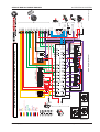
06.05.03 E - box base plate; from eng. no.: 482 18 000 / 682 18 000 + SOLAS
05.03 ill.1
Page ELECTRICAL SYSTEM - 28
Z001019/0_6_July 2008
SERVICE MANUAL MARINE ENGINES
06.05.03.01
06 ELECTRICAL SYSTEM
Components of E-box; from eng. no.: 482 18 000 / 682 18 000 + SOLAS
Designat.
Component
Description
A5
E - box
control unit
F1
F2
fuse 50 A
fuse 50 A
main fuse
glow plugs
F3
F4
fuse 50 A
fuse 5 A
glow plugs
permanent current module
F5
F6
fuse 10 A
fuse 10 A
switched current for module (K27)
fuel pump
J1
K24
plug 23-pole
relay
connection engine cable - instrument cable
fuel pump
K26-1
K26-2
relay
realy
preheating
preheating
K27
K28
relay
relay
main circuit
start
X3
S3
plug 2-pole
inversion switch
inversion switch (for SOLAS only)
(for SOLAS only)
X5
plug 35-pole
module
06.05.03.02 Connection relay K28 and K26/2
05.03 ill.2
06.05.03.03 Connection relay socket for K24, K26-1 and K27
05.03 ill.3
Z001019/0_6_July 2008
Page ELECTRICAL SYSTEM - 29
SERVICE MANUAL MARINE ENGINES
06 ELECTRICAL SYSTEM
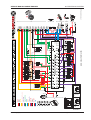
06.05.03.04 Wiring harness; from eng.no.: 482 18 000 / 682 18 000 + SOLAS
Designation
Component
Description
A5
F1
F2
F3
F4
F5
F6
F7
G1
G2
J1
K24
K26-1
K26-2
K27
K28
M1
M2
R10
X2 (S2)
X3 (S3)
X5 (A5)
X12 (B12)
X13 (B13)
X14 (B14)
X15(B15)
X16 B(16)
X17 (B17)
X18 (B18)
X19 (B19)
X20 (Y20)
X22 (B22)
X23
X26 (Y26)
Z1
Z2
Z3
Z4
Z6
E-Box
fuse 50 A
fuse 50 A
fuse 50 A
fuse 5 A
fuse 10 A
fuse 10 A
fuse 10 A
alternator
battery
plug 23--pole
relay
relay
relay
relay
relay
starter
fuel pump
glow pins
plug 2-pole
plug 2-pole
plug 35-pole
plug 3-pole
plug 5-pole
plug 3-pole
plug 3-pole
plug 2-pole
plug 2-pole
plug 3-pole
plug 1-pole
plug 2-pole
without stop
plug 6-pole
plug 2-pole
splice spot
splice spot
splice spot
splice spot
splice spot
control unit
main fuse
glow plugs
glow plugs
permanent current modul and K27
switched current for module (K27)
fuel pump (K24)
preheating - control circuit
to be provided by customer
connection engine cable - instrument cable
fuel pump
preheating - control circuit
preheating - load circuit
main circuit
start
gears switch
inversion switch ( only SOLAS)
module
boost-pressure sensor
potentiometer accelerator
pot. rack position
engine speed sensor
engine temperature sensor
exhaust gas temperature sensor
oil pressure sensor
oil pressure gauge (optional)
control solenoid
trim sensor (optional)
diagnosis
disconnection blow-by (only SOLAS)
earth connection sensor
earth connection (31) on engine
sensor supply +5V
earth connection (31) on E-box plate
shield speed sensor line
Cable numbers / principal functions:
15000-xx
15012-xx
15100-xx
30000-xx
30012-xx
31000-xx
ignition - positive
(from ignition switch)
+12 volt via main relay
and modulator unit A5
+5 volt supply voltage for sensors
battery-positive (not secured)
battery-positive (secured)
battery negative (GND)
Page ELECTRICAL SYSTEM - 30
31100-xx
601xx-01
606xx-01
Do not connect mass for sensors
with battery negative!
Sensor signal to modulator unit
A5 and/or instruments.
Exit from modulator unit A5
to display system (tachometer,
temperature display, ...)
Z001019/0_6_July 2008
SERVICE MANUAL MARINE ENGINES
Wiring harness;
from eng.no.:
482 18 000 + SOLAS
682 18 000 + SOLAS
Z001019/0_6_July 2008
06 ELECTRICAL SYSTEM
05.03 ill.4
Page ELECTRICAL SYSTEM - 31
ALL ENGINE
TYPES WITH
FOLLOWING
EXCEPTIONS
31100-10
Batt +
Batt Ign 15
Supplied by Relais
Sens ECU
Control ECU
DIAG
Start
Charge D+
Sens 5V
Sens B+ 24V
CAN
60117-01
A
60110-01
EXCEPTIONS:
ONLY FOR TYP:
MO 164M40
MO 174V40
MO 246K41
MO 256H45
MO 256K43
MO 266K43
Wiring MAP / All engines before 2007
60110-01
A
15100-05
31100-08
EXT
www.steyr-motors.com
CONNECTOR "A5" (ENGINE-CONTROL-UNIT)
STARTER
WIRING DIAGRAM / MARINE BASE - 4/6 CYLINDER - 12V
Wiring LPS / All engines before 2007
31100-08
15100-07
Page ELECTRICAL SYSTEM - 32
15100-05
60 60900-01 CAN-H
123
-01
60901-01 CAN-L
WS
60808-01 ISO
D+
R10/6
R10/4
R10/3
R10/2
R10/1
R10/5
J1 / V
J1 / U
4 CAN "L"
5 CAN "H"
6 CYL.
4 CYL.
4 CYL.
6 CYL.
B+
Optional
24V DC
X3/S3 Invers
31000-11 X3/S3 Solas
60123-01
Z6 60901-02
60900-02
Z5
60900-03
60901-03
61001-02
1
2
3
X3
4
5
6
3
2
1
K X
W
B J
H V
N C
A
G U
O D
E F T
P
Q R S
L
M
2179349/0-02-070118_tedoc
6
5
4
X23
J1
06 ELECTRICAL SYSTEM
SERVICE MANUAL MARINE ENGINES
05.03 ill.5
Z001019/0_6_July 2008
ALL ENGINE
TYPES WITH
FOLLOWING
EXCEPTIONS
31100-10
60117-01
A
Wiring LPS / All engines before 2007
G2
F8 - 5 A
31100-08
Fuel
Pump
60110-01
EXCEPTIONS:
ONLY FOR TYP:
MO 164M40
MO 174V40
MO 246K41
MO 256H45
MO 256K43
MO 266K43
Wiring MAP / All engines before 2007
15100-07
M2
Batt +
Batt Ign 15
Supplied by Relais
Sens ECU
Control ECU
DIAG
Start
Charge D+
Sens 5V
Sens B+ 24V
31100-08
60110-01
A
AUX
LPS
K27
K24
K26/1
K26/2
Preheating
Load Relay
Y20
Control
Solenoid
K28
Start
Relay
EXT
B17
B16
PED
RPOS
B14
B15
RPM
STARTER
B22
Trim-Sensor
(Option)
www.steyr-motors.com
B13
B12
ECT
Map
B18
EXT
LPS
ECT
CONNECTOR "A5" (ELECTRONIC-CONTROL-UNIT)
Main
Relay
Fuel Pump
Relay
Preheating
Control Relay
60808-01 ISO
S2
B19
Sensor Oil
Pressure
Gauge
(Option)
60 60900-01 CAN-H
123
-01
60901-01 CAN-L
WS
Gear
Switch
WIRING DIAGRAM / MARINE - 6 CYLINDER - 24V (OPTION)
15100-05
Z001019/0_6_July 2008
15100-05
D+
J1 / V
J1 / U
B-
F8
B+
61001-01
X3/1
31000-11 X3/2
60123-01
Z6 60901-02
60900-02
Z5
60900-03
60901-03
61001-02
60120-01
Batt - / 24 V
Batt + / 24V
Invers
Solas
4 CAN "L"
5 CAN "H"
60120-01
1
2
3
G1
S3
4
5
6
3
2
1
K X
W
B J
H V
N C
A
G U
O D
E F T
P
Q R S
L
M
2179345/0-02-070118_tedoc
6
5
4
X23
R10
J1
SERVICE MANUAL MARINE ENGINES
06 ELECTRICAL SYSTEM
05.03 ill.6
Page ELECTRICAL SYSTEM - 33
ALL ENGINE
TYPES WITH
FOLLOWING
EXCEPTIONS
31100-10
60117-01
A
Wiring LPS / All engines before 2007
Batt +
Batt Ign 15
Supplied by Relais
Sens ECU
Control ECU
DIAG
Start
Charge D+
Sens 5V
Sens B+ 24V
CAN
60110-01
EXCEPTIONS:
ONLY FOR TYP:
MO 164M40
MO 174V40
MO 246K41
MO 256H45
MO 256K43
MO 266K43
Wiring MAP / All engines before 2007
60110-01
A
15100-05
31100-08
www.steyr-motors.com
60 60900-01 CAN-H
123
-01
60901-01 CAN-L
WS
60808-01 ISO
WIRING DIAGRAM / MARINE - 4/6 CYLINDER - 2-POLE - 12V (OPTION)
31100-08
15100-07
Page ELECTRICAL SYSTEM - 34
15100-05
Z6 60901-02
60900-02
Z5
R10/6
R10/4
R10/3
R10/2
R10/1
R10/5
6 CYL.
4 CYL.
4 CYL.
6 CYL.
2179350/0-02-070118_tedoc
06 ELECTRICAL SYSTEM
SERVICE MANUAL MARINE ENGINES
05.03 ill.7
Z001019/0_6_July 2008
ALL ENGINE
TYPES WITH
FOLLOWING
EXCEPTIONS
31100-10
Batt +
Batt Ign 15
Supplied by Relais
Sens ECU
Control ECU
DIAG
Start
Charge D+
Sens 5V
Sens B+ 24V
CAN
60117-01
A
Wiring LPS / All engines before 2007
31100-08
60110-01
EXCEPTIONS:
ONLY FOR TYP:
MO 164M40
MO 174V40
MO 246K41
MO 256H45
MO 256K43
MO 266K43
Wiring MAP / All engines before 2007
15100-07
Z001019/0_6_July 2008
15100-05
60110-01
A
www.steyr-motors.com
60 60900-01 CAN-H
123
-01
60901-01 CAN-L
WS
60808-01 ISO
Z6 60901-02
60900-02
Z5
R10/6
R10/4
R10/3
R10/2
R10/1
R10/5
2179351/0-02-070118_tedoc
SERVICE MANUAL MARINE ENGINES
06 ELECTRICAL SYSTEM
05.03 ill.8
Page ELECTRICAL SYSTEM - 35
15100-05
31100-08
SERVICE MANUAL MARINE ENGINES
06 ELECTRICAL SYSTEM
06.06
ELECTRONICS - GENERAL
Wiring
In case of necessary repair of a cable connection, take special care that cable quality,
isolation, crimping, strand end soldering of cable sockets as well as protective varnish isolation
and/or connector locks meet the respective requirements.
Tools for crimp connections to be found in tool catalog P/N Z001002/0 "Level 4".
06.06.01 Electronic Engine Management System
The STEYR Marine engine is equipped with an Electronic Management System (EMS) that
performs the following:
* controls engine functions to ensure maximum efficiency.
* self-diagnostic to protect the engine from damage if operating parameter are exceeded.
* stores diagnostic data of EMS server circuits for maintenance and service.
Engine power is reduced if:
Operating Parameter
Effect
noticed
Panel
Indication
Additional
Tool-Readings
Action or
possible reason
High engine coolant
temperature
limit exceeded
Reduction of
engine speed
Horn ON 2x p. sec.
Gauge reading >
107 °C
Steyr Diag
Power limitation
See table trouble
shooting:
Cooling system
Defect - engine coolant
sensor or
sensor connection
Reduction of
engine speed
Horn ON 2x p. sec.
Gauge reading >
120 °C
Steyr Diag
Service code
Sensor or connector
failure; see service
code table
Exhaust temperature
limit exceeded
Reduction of
engine speed
Horn and indication
light "CEL" ON 2x
p. sec.
Steyr Diag
Power limitation
See table trouble
shooting: Raw water
cooling system
Defect - Exhaust
temperature sensor or
sensor connection
Reduction of
engine speed
Horn and indication
light "CEL" ON 2x
p. sec.
Steyr Diag
Service code
Sensor or connector
failure; see service
code table
Oil pressure below limit
Reduction of
engine speed
Horn continuos and
Oil indication light
continuos switched
ON
Steyr Diag
Power limitation
See table trouble
shooting:
Engine oil system
Defect - Oil pressure
sensor or sensor
connection
Reduction of
engine speed
Oil pressure indication Steyr Diag
light switched ON 1x Service code
p. sec.
Insufficient boost
pressure or defictive
sensor
Reduction of
engine speed
Page ELECTRICAL SYSTEM - 36
Steyr Diag
Power limitation
Sensor or connector
failure; see service
code table
See table trouble
shooting:
Air charge system
Z001019/0_6_July 2008
SERVICE MANUAL MARINE ENGINES
06 ELECTRICAL SYSTEM
Operating Parameter
Effect
noticed
Panel
Indication
Additional
Tool-Readings
Action or
possible reason
Engine speed sensor
fault
Higher or
unstable idle
speed, limited
performance
No RPM inication
on tachometer
Steyr Diag
Service code
See table trouble
shooting:
Speed sensor
Engine speed remains
at idle
No increase of
engine speed if
throttle is moved
to max.
Steyr Diag
Service code
See table trouble
shooting:
Accelerator
potentiometer failure
Governor position
system
Irregular engine
speed or stalled
engine
Steyr Diag
Service code
See table trouble
shooting:
Governing system
Inverse position shut
down (SOLAS)
Engine shut
down beyond
70° deg. angle
After engine stop
horn remains
switched ON until
ignition reset
During break in phase
Cel-ON at high
accelerator
position (more
than 75%)
Indication light
"CEL" is switched
ON
Reset through ignition
OFF and then ON
Steyr Diag
Break-in
phase
See information break
in procedure
Optical and audible warning signals as shown on the dash board, are illustrated in chapter "Operating Status
and Error Report"
06.06.02 Diagnostic system
The electronic engine management system controls the following parameters:
Oil pressure, boost pressure, coolant temperature, hi-riser (bend) temperature.
The electronic engine management system has an automatic self-test program checking all data
of electronic sensors. As soon as a fault is found, there is an optical or audible signal (refer to chart
"Error Codes").
Occurred faults remain stored until cancellation. Stored faults may be selected, analyzed and
cancelled by means of PC via diagnostic outlet.
A reference to one or several stored faults is the 5 second "TESTING" of the "CHECK-ENGINE
LAMP" and the "WARNING HORN" after ignition ON, instead of usual 0,7 seconds. (refer to chart
"Operating Status")
On the CHECK-ENGINE lamp (E) stored faults may be indicated by flashing codes. (With a
special procedure, (06.06.04) individual cancellation is possible.) Error codes are regarded both as
flashing codes as will as display by diagnostic instrument.
There are three fault categories: temporary faults, non essential faults and essential faults.
Z001019/0_6_July 2008
Page ELECTRICAL SYSTEM - 37
SERVICE MANUAL MARINE ENGINES
06 ELECTRICAL SYSTEM
06.06.03 Reading Error Codes
Entering and reading of stored faults via Check Engine Lamp and Diagnostic Outlet Plug ( X 23 ):
Needed device:
Tool No. VR00135/1
( normally closed push button switch )
connected to Diagnostic Outlet Plug X23.
In case this tool is not available:
Connect temporarily Pin - Pos. 1 with Pin - Pos. 2
of Diagnostic Plug X 23
( before ignition is turned on at key switch )
Code indication and indication sequence:
06.03 ill.1
After entering the error code indication modus the Engine
Management System will display a blink code at the Check Engine Light on the dash panel.
The blinking sequence will always begin and end with control code indication # 12. Each ERROR CODE will be
repeated 3 times to reassure your correct reading – see below bar code illustration.
Example sequence check engine light (ill.2/pos.1):
Error code # 14
1
06.03 ill.2
06.03 ill.3
Stroke = Check Engine Light illuminated for 0,3 sec. (Light Off - period within blink sequence 0,4 sec.)
Dashed Line = interruption within code indication 1,5 sec.
Solid Line = interval interruption between error code 3,0 sec.
Page ELECTRICAL SYSTEM - 38
Z001019/0_6_July 2008
SERVICE MANUAL MARINE ENGINES
06 ELECTRICAL SYSTEM
If more then one error code is stored in the Engine Management System the indication sequence will be
continued blinking additional stored error codes. To delete a memorized error code see description Indication
and Cancellation of memorized sensor and circuit faults.
For a description of the possible error codes refer to enclosed Table – Error Codes
ATTENTION: To exit from Error code indication. Tool VR00135/1 must be removed
( connection between Pin 1 to Pin 2 opened ) before ignition is turned ON again.
06.06.04 Indication and Cancellation of memorized sensor and circuit faults
Selection and clearing of stored error codes:
Procedure:
*
Ignition — OFF
*
Connect Tool VR00135/1 to Diagnostic Outlet Plug ( X 23 ) – see 06.03 ill.1
*
Ignition — ON
Note: The program changes automatically to indication of error codes.
If no error code is stored, only repeating control code reading “ CODE # 12 “ will be displayed.
Possible memorized codes are indicated as shown in the previous illustrated example ( blinking 3x
CODE # 12 i. e. 3x ERROR CODE # 14 etc. ) The sequence will be prolonged with additional codes if more
then one ERROR CODE is stored.
See Table – ERROR CODES for description
*
To delete a determined ERROR CODE from the Engine Management System concentrate for the 3rd times
flashing the desired ERROR CODE. While this ERROR CODE is displayed the third time the button ( Tool
VR00135/1 ) must be pushed and kept in this position ( contact open ).
*
The indication on the Check Engine Light changes to a fast blinking of the lamp ( app. 4 times per
sec. ). During this rapid flashing light the push button must be released ( close contact after app. 2
sec.) to delete this ERROR CODE.
Note: Any other ERROR CODE have to be selected and cleared individually following the above
mentioned procedure to delete a determined ERROR CODE.
Note: An ERROR CODE can only be deleted if no defect exists in this circuit. In case of a present active
failure, the ERROR CODE keeps reappearing until the problem has been repaired and the circuit is
properly working again.
*
Disconnect Tool VR00135/1 from Diagnostic Outlet Plug ( X 23 ) to exit from error code display.
Note: Watch indication of the Check Engine Light and the Warning Horn after ignition contact. If all
are deleted from the Engine Management System the indication resumes to 0.7 sec.
function test of Check Engine Light and the Warning Horn.
For more details see Chart – Operating Conditions - Instrument panel.
ERROR CODES
Z001019/0_6_July 2008
Page ELECTRICAL SYSTEM - 39
SERVICE MANUAL MARINE ENGINES
06 ELECTRICAL SYSTEM
06.06.05 Principle failure code list
NOTE:
CODE
Some codes may not apply due to different application!
REFER
TO
ABBREV. CIRCUIT INVOLVED DEVICE
POSSIBLE CAUSE
this code is designated for beginning or end of loop
12
Control code
13
LoMap
X12/B12
boost pressure sensor
signal level too low (short circuit or missing contact)
14
HiMap
X12/B12
boost pressure sensor
signal level too high (missing connection)
17
LoEXH
X17/B17
air charge temp. sensor
signal level too low (short circuit or missing contact)
18
HiEXH
X17/B17
air charge temp. sensor
signal level too high (missing connection)
21
LoECT
X16/B16
water temp. sensor
signal level too low (short circuit or missing contact)
22
HiECT
X16/B16
water temp. sensor
signal level too high (missing connection)
23
LoPed1
X13/B13
potentiometer accelerator
signal level entry too low
24
HiPed1
X13/B13
potentiometer accelerator
signal level entry too high
25
LoVPWR
F5/K27
main relay
low voltage supply to ECU, F5, K27
26
HiVPWR
F5/K27
main relay
too high voltage on VPROT input
27
LoVREF
X5/Z3
module, connector
too low voltage on sensor supply, possible short circuit
28
HiVREF
X5/Z1
module, connector
too high voltage on sensor supply
29
PedS
X13/B13
accelerator potentiometer
defect on pedal safety switch, pin 1-2
31
LoLPS
X18/B18
lubricant pressure sensor
signal level too low (short circuit or missing contact)
32
HiLPS
X18/B18
lubricant pressure sensor
signal level too high (missing connection)
33
LoPed2
X13/B13
potentiometer accelerator
signal level too low
34
HiPed2
X13/B13
potentiometer accelerator
signal level too high (missing connection)
35
LoRPos
X14/B14
rack position sensor
signal level too low (short circuit or missing contact)
36
HiRPos
X14/B14
rack position sensor
signal level too high (missing connection)
37
LoLOP
X18/B18
lubricant pressure sensor
signal level too low (short circuit)
38
HiLOP
X18/B18
lubricant pressure sensor
signal level too high (missing connection)
53
N_RFI
X15/B15
RPM-sensor
radio interference / sensor input
54
BadSta
M1-Pin50
K28 start assist relay
no start signal from assist solenoid
55
NoPuls
X15/B15
RPM-sensor
no speed signal during crank
56
Srpos
Y14(B14)
refer to setting rack pos.
rack calibration bad/rack position outside tolerance field
Page ELECTRICAL SYSTEM - 40
Z001019/0_6_July 2008
SERVICE MANUAL MARINE ENGINES
06 ELECTRICAL SYSTEM
CODE
ABBREV.
REFER
TO
CIRCUIT
57
Rack0
Y14(B14)
refer to setting rack pos.
99
FMSpwm
X20/Y20
actuator / solenoid
161
HiVTGc
Y28
REA unit at turbo charger
defect in governor solenoid wire circuit (Y20, main
relay K27-no frequency sent or govenor solenoid
circuit connected)
defect in circuit of actuator turbo charger (short circuit)
162
LoVTGc
Y28
REA unit at turbo charger
defect in circuit of actuator turbo charger (missing connection)
164
CELs
L2
check engine lamp
Current limit exceeded (short circuit)
165
CELo
L2
check engine lamp
missing connection or bulb blown
167
FPR_s
K24
fuel pump relay
Current limit exceeded in relay circuit (short circuit)
168
FPR_o
K24
fuel pump relay
no current detected in relay circuit (disconnection)
177
MR_s
K27
main relay
no current detected in main relay circuit (short circuit)
178
MR_o
K27
main relay
no current detected in main relay circuit (disconnection)
181
WarnLs
L3
oil pressure lamp
Current limit exceeded (short circuit)
182
WarnLo
L3
oil pressure lamp
no current in circuit of oil pressure lamp
186
BadPos
Y20
governor solenoid
Nominal-actual value difference (rack pos. error, rack jammed)
187
HiFMSC
X20/X20
governor solenoid
defect in governor wire circuit (resistance too high)
(bulb blown or missing connection)
188
LoFMSc
X20
governor solenoid
defect in governor wire circuit (resistance too low)
193
VTG_Bad
Y28
REA unit at turbo charger
defect in output circuit (short circuit or missing connection)
194
GPR_s
K26
glow assist relay
current limit exceeded in glow plug relay circuit (short circuit)
195
GPR_o
K26
glow assist relay
no current detected in glow plug relay circuit (disconnection)
201
HiTEMP
--
operation limit exceeded engine overheated
engine was operated with too high coolant temperature
202
Lop
--
operation limit exceeded - engine was operated with too low lubricant pressure
lubricant pressure too low
203
Manop
--
operation limit exceeded rack position too high
engine operated with manual movement of rack
251
ITSL_Bad
B30
position sensor - ITD
signal level too low (short circuit) on injection timing sensor
252
ITV_LoCur
Y29
proportional valve - ITD
defect in circuit of valve (no current flow)
253
ITV_HiCur
Y29
proportional valve - ITD
defect in circuit of valve (current value too high)
254
SpvP_Bad
B30
position sensor or ITD
commanded timing position can not be achieved
(sensor or injection timing device defect, eccenter
shaft jammed)
255
Spv_INI
B30
reference-position
sensor ITD
timing position calibration bad (position out of tolercance)
Z001019/0_6_July 2008
INVOLVED DEVICE
POSSIBLE CAUSE
bad rack zero position
Page ELECTRICAL SYSTEM - 41
SERVICE MANUAL MARINE ENGINES
06 ELECTRICAL SYSTEM
06.06.06 REPLACE FUSES
Preparatory works:
Engine out of operation,
disconnect battery.
Replace automatic circuit breaker
1
Swing off E-box base plate.
2
Disconnect cable from automatic circuit breaker.
3
Loosen 2 hexagon screws (ill.1/pos.1) (SW1/4") and
take off thermal circuit breaker (ill.1/pos.2).
3
2
1
NOTE:
For assembly, seal cable screw
connections with rubber varnish.
06.06 ill.1
Replace fuses
1
Remove E-box cover.
2
Remove fuse protection cap.
Pull out fuses (ill.1/pos.3)
Replace defect fuse.
Page ELECTRICAL SYSTEM - 42
Z001019/0_6_July 2008
SERVICE MANUAL MARINE ENGINES
06 ELECTRICAL SYSTEM
06.06.07 Connection J1
06.07 ill.1
Pin
Cable - no.
Explication
A
B
15000-01
15000-02
ignition 15
ignition 15
C
D
30012-07
30012-08
terminal 30
terminal 30
E
F
31000-01
31000-02
ground connection
ground connection
G
H
60616-01
31615-01
lamp - oil pressure L3
warning horn
J
K
60706-01
60614-01
const. speed switch
temperature display
L
M
61000-02
alternator D+
blind plug
N
O
60613-01
60121-01
tachometer (speed)
oil pressure gauge (optional)
P
Q
60810-01
50000-02
check engine lamp
ignition lock start
R
S
50000-03
60120-01
ignition lock start
trim (optional)
T
U
61001-02
60901-03
alternator B+ 24V DC (ifused)
CAN-low
V
W
60900-03
CAN-high
blind plug
X
Z001019/0_6_July 2008
blind plug
Page ELECTRICAL SYSTEM - 43
SERVICE MANUAL MARINE ENGINES
06 ELECTRICAL SYSTEM
06.06.08 Connection A5 and X5
06.08 ill.1
Pin
Cable no.
Designation
Explication
1
2
3
4
5
6
7
8
9
10
11
12
13
14
15
16
17
18
30012 / 01
31000 / 06
15100 / 01
free
free
60616 / 01
31555 / 01
60613 / 01
60114 / 01
60117 / 01
60112 / 01
60111 / 01
50000 / 01
60122 / 01
60900 / 01
60901 / 01
15012 / 01
15012 / 02
Vbat
GND
Vref
free
free
GPL
GPR
Tacho
ECT
LPS
RPOS
PED1
CRI
CLS
CANH
CANL
VPROT2
VPROT
19
20
21
22
23
24
25
26
27
28
29
30
31
32
33
34
35
15000 / 03
31100 / 01
free
31554 / 01
60810 / 01
31558 / 01
31615 / 01
60614 / 01
60118 / 01
60110 / 01
60706 / 01
60116 / 01
60123 / 01
60808 / 01
60113 / 01
free
31409 / 01
IGN
Gnd Vref
free
FPR
CEL
MR
WOUT
TEMP
EXT
MAP
AUX
PED2
WS
ISO
RPM
free
FMS
terminal 30
terminal 31
+ 5V
not busy
not busy
oil pressure lamp L3
preheating relay
speed instrument
engine coolant temperature sensor
oil pressure sensor
pot. rack position
pedal 1
start signal identification
gear switch
canbus high
canbus low
direct supply line to control solenoid
protected 12V (after K27 and protective
wiring in governor)
ignition terminal 15
sensor ground connection
not busy
fuel pump relay
check engine lamp
main relay (K27)
warning horn
temperature display
exhaust gas water temperature
boost pressure sensor
fixed speed
pedal 2
warning switch / Solas inversion switch
ISO 9141 (diag. cable)
engine speed sensor
not busy
approach line for control solenoid
Page ELECTRICAL SYSTEM - 44
Z001019/0_6_July 2008
SERVICE MANUAL MARINE ENGINES
06 ELECTRICAL SYSTEM
" J1" Fitting Main Connector - M1 / 01
06.06.09 Fitting main connector "J1" properly
Z001019/0_6_July 2008
Page ELECTRICAL SYSTEM - 45
SERVICE MANUAL MARINE ENGINES
06 ELECTRICAL SYSTEM
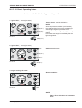
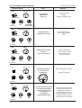
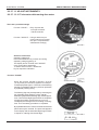
06. 07. INSTRUMENT PANEL
B
A
H
C
D
E
G
I
F
07.00 ill.1
Instrument panel, standard
A
B
C
D
E
F
tachometer
engine temperature
warning light - battery charge
combined light preheating control &
warning light engine oil pressure
warning light check engine
ignition key lock
Page ELECTRICAL SYSTEM - 46
G
H
I
blind plug - installation option for
key switch constant revolution
blind plug - installation option for
oil pressure gauge or
voltmeter 12V
audible warner
(installed to rear side of paneel)
Z001019/0_6_July 2008
SERVICE MANUAL MARINE ENGINES
06 ELECTRICAL SYSTEM
06. 07. 01 Chart - Operating Status
Instrument indication during normal operation
1. ignition ON (... until engine start)
light indication
ON
ON (0,7 sec.)
ON (0,7 sec.)
07.01 ill.1
System check - see light indication
NOTE:
At low temperature condition (cold weather)
the combined light for glow plug preheating &
warning light engine oil pressure will not
extinguish after 0,7 sec. (glow plug preheating
phase)
In this case start engine immediately after the
light extinguishes.
ON (0,7 sec.)
2. ignition ON (... until engine start)
light indication
Indication active error
ON
ON (0,7 sec.)
ON (5 sec.)
07.01 ill.2
ON (5 sec.)
3. engine running after start
Normal condition
OFF
OFF
OFF
07.01 ill.3
OFF
NOTE:
Further information see:
"Table - Error indication on Instrument
Panel"
Z001019/0_6_July 2008
Page ELECTRICAL SYSTEM - 47
SERVICE MANUAL MARINE ENGINES
06 ELECTRICAL SYSTEM
06. 07. 02 Chart - Error indication on Instrument Panel
A
C
D
E
B
A
B
C
temperature gauge - coolant
audible warner
warning light - battery charge
07.02 ill.1
D
E
combined light preheating control &
warning light engine oil pressure
warning light check engine
Operating condition: During normale engine operation, or indication in case of sensor defect while
ignition is switched ON.
Speed resp. performance limitation during engine operation
Event:
Fault
Indication status
Remarks
80° - 90°C
OFF
ON
oil pressure below min.
limit
check oil level
ON
OFF
07.02 ill.2
80° - 90°C
OFF
OFF
fault oil pressure
sensor or
sensor connection
check oil pressure sensor
(B18) and connection
FLASHING
(1x per sec.)
OFF
07.02 ill.3
NOTE: (see cap. general, D3)
ON
ON
Page ELECTRICAL SYSTEM - 48
engine overload during
break-in period
reduce throttle position
until light goes OFF
(indication during first 2
hours of operation)
Z001019/0_6_July 2008
SERVICE MANUAL MARINE ENGINES
ELECTRICAL SYSTEM
Fault
Indication status
Remarks
80° - 90°C
OFF
ON
(2x per sec.)
high exhaust
temperature
(off 80° C)
check raw water
system,
strainer, impeller pump
engine coolant
temperature to high
after cooling down,
check engine coolant
level
OFF
FLASHING
(2x per sec.)
07.02 ill.4
high approx 105°C
OFF
ON
OFF
OFF
(2x per sec.)
07.02 ill.5
120°C
OFF
ON
defect engine coolant
sensor or
sensor connection
OFF
after cooling down,
check engine coolant
level, sensor (B16)
and connection
OFF
(2x per sec.)
07.02 ill.6
80° - 90°C
OFF
OFF
instable idle speed,
no indication on
tachometer
defect speed sensor (B15)
or
sensor connection
OFF
OFF
07.02 ill.7
80° - 90°C
OFF
ON
OFF
ON
Trouble in governing loop,
involved components:
control solenoid, rack,
control gear of
unit injector,
rack position sensor
Failure in governing loop:
time limit exceed for rack
positioning. Restriction
or high friction in control
devices.Stored failure code
must be cleared memory.
Tool: PC-service program
07.02 ill.8
Z001019/0_6_July 2008
Page ELECTRICAL SYSTEM - 49
SERVICE MANUAL MARINE ENGINES
ELECTRICAL SYSTEM
Fault
Indication status
Remarks
During start attempt
ON
ON
OFF
ON
Engine will not start.
Failure in governing
circuit
Failure in governing circuit.
Positioning of rack
not possible.
Trouble shooting of control
solenoid, rack, control gear
of unit injection,
rack position sensor
07.02 ill.9
Page ELECTRICAL SYSTEM - 50
Z001019/0_6_July 2008
SERVICE MANUAL MARINE ENGINES
ELECTRICAL SYSTEM
THIS PAGE IS INTENTIONALLY BLANK
Z001019/0_6_July 2008
Page ELECTRICAL SYSTEM - 51
SERVICE MANUAL MARINE ENGINES
ELECTRICAL SYSTEM
06.07.03 Instrument panel (for SOLAS only)
A
B
F
G
I
J
C
D
E
H
07.03 ill.1
A
G
push button START (green)
H
blind plug - installation option for
oil pressure gauge or
voltmeter 12V
E
tachometer with
service hour meter
temperature gauge - coolant
warning light - battery charge
combined light preheating control &
warning light engine oil pressure
warning light - check engine light
I
emergency cut off switch
F
push button - ignition ON/OFF (red)
J
audible warning device
(installed to rear side of panel)
NOTE:
Instrument gauges are automatically illuminated if ignition is turned ON.
NOTE:
In case an inversion occured, the engine gets shut down automatically to re-establish regular
running and operation the push button Ignition (F) must be switched OFF and then ON again and
engine must be restarted with push button START (G).
B
C
D
Page ELECTRICAL SYSTEM - 52
Z001019/0_6_July 2008
SERVICE MANUAL MARINE ENGINES
ELECTRICAL SYSTEM
06.07.04 Chart - Operating Status (for SOLAS only)
Instrument indication during normal operation
1. ignition ON (... until engine start)
System check - see light indication
07.04 ill.1
ON (0,7 sec.)
ON (0,7 sec.)
ON
NOTE:
At low temperature condition (cold weather)
the combined light for glow plug preheating &
warning light engine oil pressure will not
extinguish after 0,7 sec. (glow plug preheating
phase)
In this case start engine immediately after the
light extinguishes.
ON (0,7 sec.)
2. ignition ON (... until engine start)
ON (5 sec.)
Indication active error
ON (0,7 sec.)
ON
07.04 ill.2
ON (5 sec.)
3. engine running after start
07.04 ill.3
Normal condition
NOTE:
Further information see:
"Table - Error indication on
Instrument Panel"
OFF
Z001019/0_6_July 2008
Page ELECTRICAL SYSTEM - 53
SERVICE MANUAL MARINE ENGINES
ELECTRICAL SYSTEM
06.07.05 Error Indication - Error indication on instrument panel
A
(for SOLAS only)
B
A
B
C
C
D
temperature gauge - coolant
audible warning device
warning light - battery charge
E
07.05 ill.1
D
E
combined light preheating control &
warning light engine oil pressure
warning light - check engine light
Operating condition: During normal engine operation,
or indication in case of sensor defect while ignition is switched ON.
Event:
Speed resp. performance limitation during engine operation
Fault
Indication status
ON
80° - 90°C
oil pressure below min.
limit
ON
OFF
07.05 ill.2
OFF
check oil level
OFF
80° - 90°C
fault oil pressure
sensor or
sensor connection
OFF
07.05 ill.3
Remarks
FLASHING
(1x per sec.)
check oil pressure sensor
(B18) and connection
OFF
NOTE: (see cap. general, D3)
ON
ON
Page ELECTRICAL SYSTEM - 54
engine overload during
break-in period
reduce throttle position until light
goes OFF (indication during first 2
hours of operation)
Z001019/0_6_July 2008
SERVICE MANUAL MARINE ENGINES
ELECTRICAL SYSTEM
Fault
Indication status
Remarks
80° - 90°C
ON
high exhaust
temperature
(off 80° C)
check raw water
system,
strainer, impeller pump
engine coolant
temperature to high
after cooling down,
check engine coolant
level
(2x per sec.)
OFF
OFF
07.05 ill.4
ON
FLASHING
(2x per sec.)
high approx 105°C
(2x per sec.)
OFF
07.05 ill.5
OFF
OFF
ON
120°C
defect engine coolant
sensor or
sensor connection
(2x per sec.)
OFF
07.05 ill.6
OFF
OFF
OFF
80° - 90°C
instable idle speed,
no indication on
tachometer
OFF
07.05 ill.7
OFF
defect speed sensor (B15)
or
sensor connection
OFF
80° - 90°C
ON
Trouble in governing loop,
involved components:
control solenoid, rack,
control gear of
unit injector,
rack position sensor
OFF
07.05 ill.8
after cooling down,
check engine coolant
level, sensor (B16)
and connection
OFF
Z001019/0_6_July 2008
ON
Failure in governing loop:
time limit exceed for rack
positioning. Restriction
or high friction in control
devices.Stored failure code
must be cleared memory.
Tools: PC-service program
Page ELECTRICAL SYSTEM - 55
SERVICE MANUAL MARINE ENGINES
ELECTRICAL SYSTEM
Indication status
Fault
During start attempt
ON
ON
07.05 ill.9
OFF
Page ELECTRICAL SYSTEM - 56
Engine will not start.
Failure in governing
circuit
Remarks
Failure in governing circuit.
Positioning of rack
not possible.
Trouble shooting of control
solenoid, rack, control gear
of unit injection,
rack position sensor
ON
Z001019/0_6_July 2008
SERVICE MANUAL MARINE ENGINES
ELECTRICAL SYSTEM
THIS PAGE IS INTENTIONALLY BLANK
Z001019/0_6_July 2008
Page ELECTRICAL SYSTEM - 57
SERVICE MANUAL MARINE ENGINES
ELECTRICAL SYSTEM
06. 07. 10 6 Cyl. Wiring harness instrument panel (if alternator "PRESTOLITE" is
used - old version)
Designat.
Component
F9
fuse
J1
23-pin plug
connection engine cable - instrument cable
S1
switch
ignition
S7
switch
fix-n (speed-selector switch optional)
K10
relay
charge control (90A PRESTOLITE)
L1
lamp
charge control
L2
lamp
cel - check engine lamp
L3
lamp
oil pressure / pre-heating control
P1
gauge
coolant
P2
gauge
oil pressure (optional)
P3
gauge
tachometer with running-time meter
P4
gauge
trim (optional)
H22
warning horn
XS8
1-pin plug
to lighting switch - instrument panel
XS9
2-pin plug
charging control/relay charging control (wiring harness side)
XS10
2-pin plug
charging control/relay charging control (instrument side)
X1/S1
4-pin plug
ignition
X2/L1
10-pin plug
charge control lamp
X3/L2
10-pin plug
cel - check engine lamp
X4/L3
10-pin plug
oil pressure warning lamp
X5/E10
2-pin plug
lighting coolant display
X6/P1
3-pin plug
coolant temperature gauge
X7/E11
2-pin plug
lighting oil pressure
X8/P2
3-pin plug
oil pressure gauge
X9/S7
10-pin plug
speed-selector switch (optional)
X11/P3/E12
8-pin plug
speed instrument / lighting speed instrument
X12/E13
2-pin plug
lighting trim (optional)
X22/P4
3-pin plug
trim (optional)
Page ELECTRICAL SYSTEM - 58
Description
Z001019/0_6_July 2008
SERVICE MANUAL MARINE ENGINES
ELECTRICAL SYSTEM
6 Cyl. Wiring harness instrument panel (if alternator "PRESTOLITE" is
used - old version)
07.10 ill.1
Z001019/0_6_July 2008
Page ELECTRICAL SYSTEM - 59
SERVICE MANUAL MARINE ENGINES
ELECTRICAL SYSTEM
6 Cyl. Wiring harness instrument panel (if alternator "PRESTOLITE" is
used - old version)
Designat.
Component
F9
fuse
J1
23-pin plug
connection engine cable - instrument cable
S1
switch
ignition
S7
switch
fix-n (speed-selector switch optional)
K10
relay
charge control (90A PRESTOLITE)
L1
lamp
charge control
L2
lamp
cel - check engine lamp
L3
lamp
oil pressure / pre-heating control
P1
gauge
coolant
P2
gauge
oil pressure (optional)
P3
gauge
tachometer with running-time meter
P4
gauge
trim (optional)
H22
warning horn
XS8
1-pin plug
to lighting switch - instrument panel
XS9
2-pin plug
charging control/relay charging control (wiring harness side)
XS10
2-pin plug
charging control/relay charging control (instrument side)
X1/S1
4-pin plug
ignition
X2/L1
10-pin plug
charge control lamp
X3/L2
10-pin plug
cel - check engine lamp
X4/L3
10-pin plug
oil pressure warning lamp
X5/E10
2-pin plug
lighting coolant display
X6/P1
3-pin plug
coolant temperature gauge
X7/E11
2-pin plug
lighting oil pressure
X8/P2
3-pin plug
oil pressure gauge
X9/S7
10-pin plug
speed-selector switch (optional)
X11/P3/E12
8-pin plug
speed instrument / lighting speed instrument
X12/E13
2-pin plug
lighting trim (optional)
X22/P4
3-pin plug
trim (optional)
Page ELECTRICAL SYSTEM - 60
Description
Z001019/0_6_July 2008
SERVICE MANUAL MARINE ENGINES
ELECTRICAL SYSTEM
6 Cyl. Wiring harness instrument panel (if alternator "PRESTOLITE" is
used - old version)
07.10 ill.2
Z001019/0_6_July 2008
Page ELECTRICAL SYSTEM - 61
SERVICE MANUAL MARINE ENGINES
ELECTRICAL SYSTEM
06. 07. 11 Description - Wiring harness instrument panels 4/6 cyl. marine engines
(current version)
Designat.
Component
F9
fuse 10 A
J1
23-pin plug
connection engine cable - instrument cable
S1
switch
ignition (red)
S2
switch
start (green)
S3
switch
emergency cut off (orange)
S7
switch
key switch constant revolution (optional)
L1
lamp
charge control
L2
lamp
cel - check engine lamp
L3
lamp
oil pressure / preheating conrol
P1
gauge
engine coolant temperature
P2
gauge
oil pressure (optional)
P3
gauge
tachometer with running-time meter
H22
warning horn
E10
lighting
engine coolant temperature gauge
E11
lighting
oil pressure gauge (optional)
E12
lighting
tachometer gauge
X8
1-pin plug
connector illumination switch
X24
8-pin plug
connector STEYR - display
Z1
splice
battery +
Z2
splice
battery -
Z3
splice
ignition (+)
Z4
splice
key switch constant revolution
24 V
interm. cable
charge indicator
Page ELECTRICAL SYSTEM - 62
Description
Z001019/0_6_July 2008
Z001019/0_6_July 2008
W
B J
H V
N C
A
G U
O D
E F T
P
Q R S
K X
30012-07
30012-08
31000-01
3100-02
60616-01
31615-01
60706-01
60614-01
61000-02
2
3
4
5
6
7
8
9
10
11
J1 / B
J1 / C
J1 / D
J1 / E
J1 / F
J1 / G
J1 / H
J1 / J
J1 / K
J1 / L
(no connection)
60810-01
50000-02
50000-03
60120-01
61001-01 B+ / 24V
(no connection)
60121-01
60901-03
60900-03
14
15
16
17
18
12
21
22
19
20
J1 / O
J1 / P
J1 / Q
J1 / R
J1 / S
J1 / T
J1 / U
J1 / V
J1 / W
J1 / X
Trim (Option)
60613-01
13
Ground shield
J1 / N
31000-16
15000-02
1
J1 / A
J1 / M
15000-01
No./colours of shielded wire correspond to
individual cable No. (15000-01)
J1
L
M
Z1
Fuse
10A
F9
1
5
6
Ignition
Switch
S1
7
2
- Start
Z3
1
Charge
Control
Lamp
L1
1
2
Check
Engine
Lamp
L2
2
80
12
0
250
10
0
°F 210
°C
+
G
_
Engine
Coolant
Temperature
Gauge
P1
105 175
58000-01
Connector
Illumination
X8 switch
Z2
22
Z4
13
21
14
1
2
Opt. Key
Switch-Constant
Revolution
S7
Lighting
ECTGauge
E10
www.steyr-motors.com
1
OILPreheating
control
Lamp
L3
40
WIRING DIAGRAM / INSTRUMENT PANEL - 4/6 CYLINDER - 12 V
G
_
1
2
Lighting
Opt. Gauge
Oil-Pressure
E11
Batt +
Batt Sens ECU
Control ECU
61 +24V
+
Opt. Gauge
OilPressure
P2
0
20
30
40
2
4
3
RPMGauge
P3
10
1
5
Lighting
RPMGauge
E12
_
1
2
3
rpm x 1000
4
0
1
bar
3 85 4
2
°C
73
77.8
TEMP
TEMP/°C
50
1
120
6
5
X 24
8
6
1 2 3 4
2,8
6.3
OIL
OIL/BAR
5
RPM
65
0
1500
2650
4
34
10.0
22
SPEED/KN
3 4
48.08.56N 102.41.11W
014.27.47W 57,4
117 14:05
49.16.45N
22:57
MAIN
SWITCH
2179338/D-02-070627_tedoc
Start
Charge
Illumination
Option
15
60 CAN
+
Warning
Horn
H22
SCC
STEYR-CONTROL-CENTER
SERVICE MANUAL MARINE ENGINES
ELECTRICAL SYSTEM
Page ELECTRICAL SYSTEM - 63
K X
W
B J
H V
N C
A
G U
O D
E F T
P
Q R S
L
M
Page ELECTRICAL SYSTEM - 64
2
3
4
5
6
7
8
9
10
11
J1 / B
J1 / C
J1 / D
J1 / E
J1 / F
J1 / G
J1 / H
J1 / J
J1 / K
J1 / L
Trim (Option)
(no connection)
(no connection)
19
20
J1 / X
60900-03
60901-03
J1 / W
61001-01 B+ / 24V
60120-01
22
18
J1 / S
50000-03
J1 / V
17
J1 / R
50000-02
21
16
J1 / Q
60810-01
J1 / U
15
J1 / P
60121-01
Ground shield
12
14
J1 / O
60613-01
31000-16
61000-02
60614-01
60706-01
31615-01
60616-01
3100-02
31000-01
30012-08
30012-07
15000-02
J1 / T
13
J1 / N
J1 / M
1
J1 / A
15000-01
No./colours of shielded wire correspond to
individual cable No. (15000-01)
J1
Z1
Fuse
10A
F9
1
5
6
Ignition
Switch
S1
7
2
30
Intermediate
Cable Charge
Indicator
24 V
85 86 87a 87
- Start
Z3
1
Charge
Control
Lamp
L1
1
12
0
250
10
0
°F 210
°C
1
2
+
G
_
58000-01
X8
1
14
Z2
22
Z4
13
21
G
_
1
2
Batt +
Batt Sens ECU
Control ECU
61 +24V
+
Opt. Gauge
Lighting
Opt. Key
OilOpt. Gauge
Switch-Constant
Pressure
Oil-Pressure
Revolution
P2
E11
S7
Connector
Illumination
switch
2
Lighting
ECTGauge
E10
www.steyr-motors.com
2
Check
Engine
Lamp
L2
80
105 175
OILEngine
Preheating
Coolant
control
Temperature
Lamp
Gauge
L3
P1
40
WIRING DIAGRAM / INSTRUMENT PANEL - 4/6 CYLINDER - 24V (OPTION)
0
30
40
2
4
3
RPMGauge
P3
10
20
1
5
Lighting
RPMGauge
E12
_
0
1
73
77.8
°C
3 85 4
TEMP
TEMP/°C
50
1
2
5
4
120
6
5
X 24
8
6
2
3
rpm x 1000
1 2 3 4
2,8
6.3
OIL
OIL/BAR
1
RPM
65
0
1500
2650
4
bar
3 4
34
10.0
22
SPEED/KN
MAIN
SWITCH
2179339/D-02-070627_tedoc
Start
Charge
Illumination
Option
15
60 CAN
+
Warning
Horn
H22
SCC
48.08.56N 102.41.11W
014.27.47W 57,4
117 14:05
49.16.45N
22:57
STEYR-CONTROL-CENTER
ELECTRICAL SYSTEM
SERVICE MANUAL MARINE ENGINES
Z001019/0_6_July 2008
Z001019/0_6_July 2008
K X
W
B J
H V
N C
A
G U
O D
E F T
P
Q R S
L
M
2
3
4
5
6
7
8
9
10
11
J1 / B
J1 / C
J1 / D
J1 / E
J1 / F
J1 / G
J1 / H
J1 / J
J1 / K
J1 / L
ohne Anschlag (no connection)
ohne Anschlag (no connection)
21
22
19
20
J1 / U
J1 / V
J1 / W
J1 / X
60900-03
60901-03
61001-01 B+ / 24V
Optional 24 V
12
J1 / T
Trim (Option)
18
J1 / S
60120-01
50000-03
17
50000-02
60810-01
J1 / R
15
J1 / P
60121-01
Ground shield
16
14
J1 / O
60613-01
31000-16
61000-02
60614-01
60706-01
31615-01
60616-01
3100-02
31000-01
30012-08
30012-07
15000-02
Z1
Fuse
10A
F9
3
4
3
M
M
- Start
4
1
Z3
2
Emergency Charge
IGN (red) START CUT OFF Control
Switch
Lamp
ON/OFF (green)
S3
S2
L1
S1
J1 / Q
13
J1 / N
J1 / M
1
J1 / A
15000-01
No./colours of shielded wire correspond to
individual cable No. (15000-01)
J1
1
1
2
OILPreheating
control
Lamp
L3
80
12
0
250
10
0
°F 210
°C
+
G
_
Engine
Coolant
Temperature
Gauge
P1
105 175
58000-01
Connector
Illumination
X8 switch
Z2
22
Z4
13
+
G
_
1
2
Opt. Gauge
Lighting
OilOpt. Gauge
Pressure Oil-Pressure
P2
E11
Batt +
Batt Sens ECU
Control ECU
61 +24V
21
14
1
2
Opt. Key
Switch-Constant
Revolution
S7
Lighting
ECTGauge
E10
www.steyr-motors.com
2
Check
Engine
Lamp
L2
40
WIRING DIAGRAM / INSTR. PANEL - 4/6 CYL. - Solas - 12V (OPTION)
0
20
30
40
2
4
3
RPMGauge
P3
10
1
5
Lighting
RPMGauge
E12
_
4
1
2
3
rpm x 1000
4
3 85 4
°C
73
77.8
TEMP
TEMP/°C
50
1
2
5
120
6
5
1 2 3 4
X 24
8
6
65
OIL
OIL/BAR
2,8
6.3
0
RPM
0
1
bar
1500
2650
3 4
34
10.0
22
SPEED/KN
MAIN
SWITCH
2179340/D-02-070627_tedoc
Start
Charge
Illumination
Option
15
60 CAN
+
Warning
Horn
H22
SCC
48.08.56N 102.41.11W
014.27.47W 57,4
117 14:05
49.16.45N
22:57
STEYR-CONTROL-CENTER
SERVICE MANUAL MARINE ENGINES
ELECTRICAL SYSTEM
Page ELECTRICAL SYSTEM - 65
Page ELECTRICAL SYSTEM - 66
K X
W
B J
H V
N C
A
G U
O D
E F T
P
Q R S
L
M
30012-07
30012-08
31000-01
3100-02
60616-01
31615-01
60706-01
60614-01
61000-02
2
3
4
5
6
7
8
9
10
11
J1 / B
J1 / C
J1 / D
J1 / E
J1 / F
J1 / G
J1 / H
J1 / J
J1 / K
J1 / L
(no connection)
(no connection)
60900-03
22
19
20
J1 / V
J1 / W
J1 / X
Trim (Option)
60901-03
18
J1 / S
60120-01
50000-03
21
17
J1 / R
50000-02
J1 / U
16
J1 / Q
60810-01
61001-01 B+ / 24V
15
J1 / P
60121-01
12
14
J1 / O
Ground shield
J1 / T
13
J1 / N
60613-01
31000-16
15000-02
1
J1 / A
J1 / M
15000-01
No./colours of shielded wire correspond to
individual cable No. (15000-01)
J1
Z1
Fuse
10A
F9
3
4
3
M
M
- Start
4
Z3
1
2
Emergency Charge
IGN (red) START CUT OFF Control
Switch
Lamp
ON/OFF (green)
S3
S2
L1
S1
85 86 87a 87
1
2
Check
Engine
Lamp
L2
80
12
0
250
10
0
°F 210
°C
1
2
+
G
_
Engine
OILCoolant
Preheating
Temperature
control
Gauge
Lamp
P1
L3
105 175
58000-01
www.steyr-motors.com
30
Intermediate
Cable Charge
Indicator
24 V
40
2
Connector
Illumination
X8 switch
1
Lighting
ECTGauge
E10
14
Z2
22
21
+
G
_
1
Batt +
Batt Sens ECU
Control ECU
61 +24V
Z4
13
2
Opt. Gauge
Lighting
Opt. Key
OilOpt. Gauge
Switch-Constant
Pressure Oil-Pressure
Revolution
P2
E11
S7
WIRING DIAGRAM / INSTR. PANEL - 4/6 CYL. - Solas - 24V (OPTION)
0
20
30
40
2
4
3
RPMGauge
P3
10
1
5
Lighting
RPMGauge
E12
_
4
1
2
3
rpm x 1000
4
3 85 4
73
77.8
°C
120
6
5
X 24
TEMP
TEMP/°C
50
1
2
5
1 2 3 4
2,8
6.3
OIL
OIL/BAR
8
6
65
0
RPM
0
1
bar
1500
2650
3 4
34
10.0
22
SPEED/KN
MAIN
SWITCH
2179341/D-03-070627-tedoc
Start
Charge
Illumination
Option
15
60 CAN
+
Warning
Horn
H22
SCC
48.08.56N 102.41.11W
014.27.47W 57,4
117 14:05
49.16.45N
22:57
STEYR-CONTROL-CENTER
ELECTRICAL SYSTEM
SERVICE MANUAL MARINE ENGINES
Z001019/0_6_July 2008
SERVICE MANUAL MARINE ENGINES
ELECTRICAL SYSTEM
THIS PAGE IS INTENTIONALLY BLANK
Z001019/0_6_July 2008
Page ELECTRICAL SYSTEM - 67
ELECTRICAL SYSTEM
SERVICE MANUAL MARINE ENGINES
06. 07. 13 ADJUST INSTRUMENTS
06. 07. 13. 01 Tachometer with running-time meter
There are 2 possible settings
Function "PULSE": - Entry of pulse rate
12,18 per revolution
- inductive sender
Function "ADJUST": - Using a reference rpm
meter (manual rpm meter),
the rpm is compared and
calibrated accordingly.
07.13 ill.1
Selection of function
Operating voltage off.
Press and hold down key on back of housing.
Operating voltage (ignition) on.
The display shows "PULSE" and "ADJUST"
every 2 seconds in alternation.
To select shown function, release the
key for respective indication.
Function "PULSE"
When the function PULSE is selected, "P12.18"
(12.18 pulses per revolution) appears for example
on the display after approx. 3 seconds, with a flashing
last digit. Immediately start entry of known pulse rate
by repeated pressing of key.
07.13 ill.2
The flashing digit may be adjusted by activating the
key (possible pulse settings: 0.50 to 399.99).
After having adjusted the flashing digit, wait for approx.
3 sec. Then the next digit begins to flash. At completion
of pulse rate setting, activate the key no more.
The display then changes over to counting of runningtime. Thus the setting procedure is completed.
By repeated selection of function PULSE the selected
pulse rate may be checked. The pulse rate appears
on the display and the individual digits begin to flash
in sequence, starting with the last digit.
07.13 ill.3
P-12,18
Page ELECTRICAL SYSTEM - 68
Z001019/0_6_July 2008
SERVICE MANUAL MARINE ENGINES
ELECTRICAL SYSTEM
Function "ADJUSt"
When selecting the function "ADJUST", the rpm.
display may be adjusted between 30 and 100 % of
the measuring range.
Using a reference rpm meter (manual rpm meter),
the rpm indicator is compared.
Fine adjustment requires two persons, one to operate
the instrument and the other one to operate the
manual rpm meter on the axis of the engine's
crankshaft. Extreme caution is required! Do not wear
loose clothing!
When the function ADJUSt is selected, UP or dn (UP
or DOWN) appears in alternation on the display after
approx. 3 seconds.
If, for example, the key is pressed and held down
when UP is displayed, the pointer deflection changes
upwards (for "dn" analogously downwards).
If you release the key for 2 seconds and then press
it again, the pointer deflection changes downwards.
At the beginning, the pointer deflection changes very
slowly which permits a very precise fine adjustment.
With a short release of the key, the procedure is
repeated. With a longer pressing of the key, the
pointer deflection will change faster. Release the key
as soon as the fine adjustment corresponds to the
reference rpm. The display then changes to counting
of running-time. Fine adjustment is completed.
07.13 ill.4
Fine Adjustment:
During normal operation of the indicator, a fine
adjustment is possible by using the key. The
adjustment range is +/- 20 % of the actual reading.
Press the key, with voltage supply on.
On the display appears A 0.0
By pressing and holding the key, the adjustment
factor increases in steps of 0,5%.
If you release the key for 2 seconds and then press
it again, the adjustment factor decreases in steps of
0,5%.
If the key is not pressed for more than 5 seconds, the
adjustment factor will be stored and the indicator
switches back to the normal running-time display.
Z001019/0_6_July 2008
07.13 ill.5
Page ELECTRICAL SYSTEM - 69
ELECTRICAL SYSTEM
SERVICE MANUAL MARINE ENGINES
06. 07. 14 REPLACE INSTRUMENTS
06. 07. 14. 01. General notes on safety
Safety instructions
No smoking!
No open fire lights!
This product has been developed, produced and tested in compliance with the basic safety
requirements of EC directives and in accordance with the established state of the art.
Use our product for the intended purpose only.
The consequences of use of the product for other than the intended purpose may be personal injury
and damage to property as well as environmental damage.
The unit is designed for use in sports boats.
Record data of other instruments with transient electronic memories.
Please note during installation:
The product should be installed by your boatyard or by a person specialised in the installation of
such devices.
If you wish to carry out installation yourself, wear suitable working clothing. Do not wear loosefitting clothing. This may be caught by moving parts. If you have long hair, wear a hair net.
When working on electric equipment, do not wear any metallic or conductive jewellery such as
chains, bracelets, rings etc.
Before beginning work, disconnect the negative pole of the battery, since otherwise there is a risk
of a short ciruit. Short circuits can cause cable fires, battery explosions and damage to other
electronic storage systems. Please note that when the battery is disconnected, all transient
electronic memories lose the values entered and have to be reprogrammed.
With petrol engines, allow the engine compartment fan to run before beginning work in the engine
compartment.
At the installation site, make sure there is sufficient space behind drilled holes or the installation
aperture.
First drill small holes at the installation apertures, and enlarge if necessary using tapered drills,
compass saws, fretsaws of files. Deburr edges.The safety instructions of the hand tool manufacturer
must be observed.
If work has to be carried out without interruptions in voltage, only insulated tools may be used.
The electrical outputs of the display unit and the connected cables must be protected from direct
contact and damage. To this end, the cables used must have adequate insulation and/or dielectric
strenght, and the contacts must be shockproof.
The electrical conductive parts of the connected consumers must also be protected from direct
contact by suitable means. The installation of bare metal cables and contacts is forbidden.
After installation, please note:
Clamp the earthing cable firmly to the negative pole of the battery.
Enter/program the values of the transient electronic memories again.
Test all functions.
Page ELECTRICAL SYSTEM - 70
Z001019/0_6_July 2008
SERVICE MANUAL MARINE ENGINES
ELECTRICAL SYSTEM
Safety Instructions
(electrical connection):
To install the electric cables, use existing cable ducts and looms, but do not run the cables paralle
to ignition cables or parallel to cables leading powerful consumers. Secure the cables using cable
binders or adhesive tape.
Do not run the cables over moving parts.
Ensure that the cables are not exposed to any tensile, compressive or shear forces.
If the cables have to be run through drilled holes, protect the cables using grommets or rubber
bushings etc.
Use only a cable stripper to strip the cables. Adjust the cable stripper so that the individual strands
are not damaged or cut off.
New connections should only be made using soft solder, or with commercial crimp connectors.
Crimped connections should only be made using cable crimping pliers. The safety instructions of
the hand tool manufacturer must be observed. Insulate exposed leads in such a way that short
circuits cannot occur.
Caution: Risk of short circuit through faulty junctions or damaged cables.
Short circuits in the electrical system can cause cable fires, battery explosions and damage to
other electronic systems. For this reason, all connections in the voltage supply system must be
either soldered or fitted with weldable connectors and adequately insulated.
Pay particular attention to correct earth connections.
Incorrect connections can lead to short circuits. The cables must only be connected in accordance
with the electrical terminal connection diagram.
Z001019/0_6_July 2008
Page ELECTRICAL SYSTEM - 71
SERVICE MANUAL MARINE ENGINES
ELECTRICAL SYSTEM
06. 07. 14. 02 Audible warner, H22
control unit
07.14 ill.1
sensor
exhaust gas
temperature
Page ELECTRICAL SYSTEM - 72
sensor
engine coolant
sensor
oil pressure
Z001019/0_6_July 2008
SERVICE MANUAL MARINE ENGINES
ELECTRICAL SYSTEM
06. 07. 14. 03 Circuit diagram voltmeter (optional)
07.14 ill.2
06. 07. 14. 04 Circuit diagram oil pressure gauge (optional, sensor B19 - gauge P2)
single instruments
07.14 ill.3
Z001019/0_6_July 2008
double instruments (requires special sensor)
sensor marking "G"
one sensor for two
two displays
displays
Page ELECTRICAL SYSTEM - 73
SERVICE MANUAL MARINE ENGINES
ELECTRICAL SYSTEM
06.08.01 Potentiometer Accelerator, B13
1
Remove plug housing.
2
Unscrew hexagon nut of accelerator lever, remove
lever.
3
Loosen 2 hexagon screws. Remove accelerator.
Throttle potentiometer B13 (accelerator)
(= connector X13)
In case of defective potentiometer accelerator B13,
service codes 23, 24 or 29 will flash.
NOTE:
R1
08.01 ill.1
First check cables and
connections.
Resistance between terminals 3 and 1;
approximately 1,2 kOhm resistance value switch to
infinetely after moving throttle lever from idle position.
Switch contact should open within the first 10% of
throttle lever (pedal) movement.
R2
Resistance between terminals 5 and 4; 1,2 kOhm
R3
Resistance between terminals 5 and 2; 2,2 kOhm
for normal position of potentiometer accelerator ;
1,4 kOhm at "full speed " max. throttle position.
1 2 3 4 5
08.01 ill.2
Wiring Circuit - Potentiometer P/N 2176860/0
~ 1k
1
R1
~9
3
5
~ 1k
+
~ 1k
2
-
R3
R2
4
08.01 ill.3
Page ELECTRICAL SYSTEM - 74
Z001019/0_6_July 2008
SERVICE MANUAL MARINE ENGINES
ELECTRICAL SYSTEM
06.08.02 Voltage regulator 24V-12V equalizer
Powersupply to equalizer recomandet wire gauge size.
Starter must be connecting by customer use a wire min. AWG 0 (50 mm²)
connect a red wire AWG 8 (6 mm²) at battery "A" positiv terminal +12V
connect a red wire AWG 6 (10 mm²) at battery "B" positiv terminal +24V
connect a black wire AWG 6 (10 mm²) directly at battery "A" negativ terminal.
Battery equalizer
+24V
25A
20A
GND
BLACK AWG 6
30A
12V Protected
Output
RED AWG 6
24V LOAD
(STARTER , ALTERNATOR,
power supply glow , .....)
OUT 12V
RED AWG 8
(*)
“A”
“B”
08.02 ill.1
* Note:......Mainswitsches are mechanically interlinked.
X21 ARMATUREN PLUG 6-POLE: --> USE ONLY 12 VOLT INSTRUMENTS
pin1
pin2
pin3
pin4
pin5
pin6
60810--> check engine lampe (12V/2W)
60616--> glow lamp (12V/2W)
60614--> temperature instruments (12V)
60613--> engine speed instruments (12V)
50000--> starter terminal 50 (detection of start)
15000--> ignition connect it to the ignition-switch of the vehicle (protect with 5 Amp fuse)
Note:
The glow lamp has 2 functions --> at first it works as glow lamp after start it works as oil
pressure lamp.
ALTERNATOR
B+ must be connection by customer --> use a wire AWG 6 (10 mm²) charging control --> must be connecting
by customer.
ATTENTION:
Please observer and follow Original inclosed
manufactures recommentation!
Z001019/0_6_July 2008
08.02 ill.2
Page ELECTRICAL SYSTEM - 75
SERVICE MANUAL MARINE ENGINES
ELECTRICAL SYSTEM
06.08.03 DC - DC converter
DC-DC Converter
IVO 8770
CIRCUIT DIAGRAM
IE
Batt "A"
IA
16A
25A
24VDC
U1
Engine
U2
G
12VDC
Batt "B"
Batt "C"
Page ELECTRICAL SYSTEM - 76
Z001019/0_6_July 2008
SERVICE MANUAL MARINE ENGINES
ELECTRICAL SYSTEM
THIS PAGE IS INTENTIONALLY BLANK
Z001019/0_6_July 2008
Page ELECTRICAL SYSTEM - 77
SERVICE MANUAL MARINE ENGINES
ELECTRICAL SYSTEM
to engine number 48226999
06.10
SENDER AND SENSOR OVERVIEW
06.10.01 Component configuration 4 cyl. engine
164/174
94/114/144
10.01 ill.1
CODE
CODE
KURZNAME
ABBREVIATION
KURZNAME
ABBREVIATION
BESCHREIBUNG
DESCRIPTION
BESCHREIBUNG
DESCRIPTION
Stecker Ölmanometer (Option)
Connector oil pressure gauge (optional)
Stecker Trimmanzeige (Option)
Connector trim (optional)
MAP
Ladedrucksensor
Boost-pressure sensor
PED
Gaspedal
Potentiometer accelerator
RPOS
Regelstangensensor
Rack position sensor
DIAG
Diagnose - Stecker
Diagnosis - plug
RPM
Motordrehzahlsensor
Sensor engine speed
FMS
Steuermagnet
Control solenoid
ECT
ECT
Kühlflüssigkeitstemperatursensor
Sensor engine coolant temperature
Stecker Getriebeschalter (Option)
Connector gear switch (optional)
EXT
Abgastemperatursensor
Sensor exhaust gas temperature
Inversionsschalter (Nur bei SOLAS)
Inversion switch (only for SOLAS)
LPS
Öldrucksensor
Lubricant pressure sensor
Abschaltventil (Nur bei SOLAS)
Blow - by (only for SOLAS)
Page ELECTRICAL SYSTEM - 78
J1
Verbindungsstecker Motor - EMS
Connector engine cable - EMS
Z001019/0_6_July 2008
SERVICE MANUAL MARINE ENGINES
ELECTRICAL SYSTEM
from engine number 48227000
07002
CODE
BESCHREIBUNG
DESCRIPTION
CODE
BESCHREIBUNG
DESCRIPTION
B12
Ladedrucksensor
Boost-pressure sensor
X19
Stecker Ölmanometer (Option)
Connector oil pressure gauge (optional)
B13
Gaspedal
Potentiometer accelerator
X22
Stecker Trimmanzeige (Option)
Connector trim (optional)
B14
Regelstangensensor
Rack position sensor
J1
B15
Motordrehzahlsensor
Sensor engine speed
X23
Diagnose - Stecker
Diagnosis - plug
B16
Kühlflüssigkeittemperatursensor
Sensor engine coolant temperature
Y20
Steuermagnet
Control solenoid
B17
Abgastemperatursensor
Sensor exhaust gas temperature
X2
Stecker Getriebeschalter (Option)
Connector gear switch (optional)
B18
Öldrucksensor
Lubricant pressure sensor
S3
Inversionsschalter (nur bei SOLAS)
Inversion switch (only for SOLAS)
Z001019/0_6_July 2008
Haupt-Verbindungsstecker
Main connector
Page ELECTRICAL SYSTEM - 79
SERVICE MANUAL MARINE ENGINES
ELECTRICAL SYSTEM
06.10.02 Component configuration 6 cyl. engine
to engine number 68226999
246/256/
266
126/166/
236
10.02 ill.1
CODE
CODE
KURZNAME
ABBREVIATION
KURZNAME
ABBREVIATION
BESCHREIBUNG
DESCRIPTION
BESCHREIBUNG
DESCRIPTION
Stecker Ölmanometer (Option)
Connector oil pressure gauge (optional)
Stecker Trimmanzeige (Option)
Connector trim (optional)
MAP
Ladedrucksensor
Boost-pressure sensor
PED
Gaspedal
Potentiometer accelerator
RPOS
Regelstangensensor
Rack position sensor
DIAG
Diagnose - Stecker
Diagnosis - plug
RPM
Motordrehzahlsensor
Sensor engine speed
FMS
Steuermagnet
Control solenoid
ECT
ECT
Kühlflüssigkeitstemperatursensor
Sensor engine coolant temperature
Stecker Getriebeschalter (Option)
Connector gear switch (optional)
EXT
Abgastemperatursensor
Sensor exhaust gas temperature
Inversionsschalter (Nur bei SOLAS)
Inversion switch (only for SOLAS)
LPS
Öldrucksensor
Lubricant pressure sensor
Abschaltventil (Nur bei SOLAS)
Blow - by (only for SOLAS)
Page ELECTRICAL SYSTEM - 80
J1
Verbindungsstecker Motor - EMS
Connector engine cable - EMS
Z001019/0_6_July 2008
SERVICE MANUAL MARINE ENGINES
ELECTRICAL SYSTEM
from engine number 68227000
07003
CODE
BESCHREIBUNG
DESCRIPTION
CODE
BESCHREIBUNG
DESCRIPTION
B12
Ladedrucksensor
Boost-pressure sensor
X19
Stecker Ölmanometer (Option)
Connector oil pressure gauge (optional)
B13
Gaspedal
Potentiometer accelerator
X22
Stecker Trimmanzeige (Option)
Connector trim (optional)
B14
Regelstangensensor
Rack position sensor
J1
B15
Motordrehzahlsensor
Sensor engine speed
X23
Diagnose - Stecker
Diagnosis - plug
B16
Kühlflüssigkeittemperatursensor
Sensor engine coolant temperature
Y20
Steuermagnet
Control solenoid
B17
Abgastemperatursensor
Sensor exhaust gas temperature
X2
Stecker Getriebeschalter (Option)
Connector gear switch (optional)
B18
Öldrucksensor
Lubricant pressure sensor
S3
Inversionsschalter (nur bei SOLAS)
Inversion switch (only for SOLAS)
Z001019/0_6_July 2008
Haupt-Verbindungsstecker
Main connector
Page ELECTRICAL SYSTEM - 81
SERVICE MANUAL MARINE ENGINES
ELECTRICAL SYSTEM
06.10.03 Calibration of rack position
This procedure must be carried out if any of the following has been done:
- Control solenoid has been disassembled or replaced, refer to 03. 08. 01.
- Rack position sensor has been disassembled or replaced, refer to 03. 08. 03.
- Engine control unit has been replaced.
- Rack or linkage lever have been replaced or loosened.
E
F
1
D C
B
A
10.03 ill.2
10.03 ill.1
NOTE:
Ensure that the ignition is turned off.
1
Remove threaded pin from position A (ill. 1).
2
Manually move rack (ill.1/B) forward until borehole (ill.1/C) is over tapped hole (ill.1/D) and fix
with threaded pin. The pin must be fastened hand tight and sit correctly in the rack, see ill. 2.
above.
3
Turn on ignition,rack position will be automatically stored in the ECU A5.
Storage process will take approx. 20 sec.
4
Turn off ignition.
5
Loosen threaded pin and screw it into rear bulkhead wall (ill.1/A).
NOTE:
If storage in ECU A5 was unsuccessful, error code 56 will be detected.
Refer to Error Codes.
NOTE:
The rack position sensor is magnetism
sensitive. All external magnets must
be kept away as the may disturb the
sensor.
Page ELECTRICAL SYSTEM - 82
Z001019/0_6_July 2008
SERVICE MANUAL MARINE ENGINES
ELECTRICAL SYSTEM
06.10.04 Replace Senders, Sensors
06.10.04.01 Exhaust gas temperature sensor, B17
1
Unlock plug (ill.1/pos.1) and remove.
2
Unscrew temperature sensor (ill.1/pos.2) (SW19)
2
1
10.04 ill.1
06.10.04.02 Engine temperature sensor, B16
1
Remove plug housing (ill.2/pos.1).
2
Unscrew engine temperature sensor.
1
10.04 ill.2
06.10.04.03 Speed sensor, B15
1
Press catch spring and remove plug.
2
Loosen hexagon screw (SW10), pull out sensor.
ATTENTION: For assembly, use new 0-ring.
Grease O-ring and put it on.
06.10.04.04 Boost pressure sensor, B12
for engines 94 / 114 / 144 / 126 / 166 / 236 only
1
10.04 ill.3
Remove hose from exhaust manifold.
2
2
ATTENTION: Do not remove hose from boost
pressure sensor.
2
Press retaining clip against plug housing (ill.4/pos.1),
remove plug.
3
Loosen two hexagon screws (SW10), remove boost
pressure sensor (ill.4/pos.2).
NOTE:
Z001019/0_6_July 2008
For assembly, take care of the 2
sealing cushions of plug housing.
1
10.04 ill.4
Page ELECTRICAL SYSTEM - 83
ELECTRICAL SYSTEM
SERVICE MANUAL MARINE ENGINES
Boost pressure sensor, B12
for engines 164 / 174 / 246 / 256 / 266 only
1
Remove cable strap, lift shackle at plug and pull off
plug.
2
Loosen clamp (SW6) and pull off hose.
3
Loosen union nut (SW17) by holding up at sensor
(SW32). Remove sensor
Assembly is done in reverse order off disassembly.
NOTE:
Wetten the thread from the new sensor
with LOCTITE 243. Thigthen union
nut solid.
10.04 ill.5
06.10.04.05 Rack position feedback sensor, B14
1
Remove retaining clip, remove plug housing
(ill.6/pos.1).
2
Disassemble control solenoid, refer to 03.08.01
3
Loosen 2 cylinder screws with hexagon socket (SW
3), remove sensor (ill.6/pos.2).
1
2
Assembly is done according to assembly
of control solenoid, refer to 03.08.
10.04 ill.6
06.10.04.06 Oil pressure sensor, B18
1
Remove plug housing.
2
Unscrew oil pressure sensor (ill.7/pos.1) from mount
(ill.7/pos.2).
ATTENTION: Collect running out motor oil in a
suitable vessel.
1
2
10.04 ill.7
06.10.04.07 Potentiometer Accelerator, B13
1
Disassemble indexing plate (ill.8+9/pos.1).
2
Remove plug housing (ill.8+9/pos.2).
3
Unscrew hexagon nut of accelerator lever (ill.8+9/
pos.3), remove lever.
4
Loosen 2 hexagon screws. Remove accelerator
(ill.8+9/pos.4).
3
1
4
2
10.04 ill.8
Page ELECTRICAL SYSTEM - 84
Z001019/0_6_July 2008
SERVICE MANUAL MARINE ENGINES
ELECTRICAL SYSTEM
3
1
4
2
10.04 ill. 9
06.10.05 Check Sensors and Switches
06.10.05.01 A
Check rack position feedback sensor
B14 (= connector X14)
In case of defective rack position feedback sensor
B14, service codes (35) and (36) will flash.
NOTE:
First always check cables and connections.
10.05 A ill.1
Final check:
C
Disassemble rack position feedback sensor
from control solenoid.
1
A
Check resistance between terminals A and C with a
digital ohmmeter. Resistance must be between
2,2 kOhm ± 10 %.
10.05 A ill.2
2
Measure resistance between terminals B and C with
extended shaft. Resistance must be
0,5 kOhm ± 10 %.
C
B
10.05 A ill.3
Z001019/0_6_July 2008
Page ELECTRICAL SYSTEM - 85
ELECTRICAL SYSTEM
3
SERVICE MANUAL MARINE ENGINES
Measure resistance between
terminals B and C with inserted shaft.
Resistance must be
2,4 kOhm ± 10 %.
C
B
When a failure was found during one
of above checks, replace rack position
feedback sensor B14.
10.05 A ill.4
06.10.05.01 B
Check rack position feedback sensor
B14 (= connector X14)
In case of defective rack position feedback sensor
B14, service codes 35 and 36 or 186 will flash.
NOTE:
First always check cables and connections.
10.05 B ill.1
Final check:
C
Disassemble rack position feedback sensor
from control solenoid.
A
1
Supply terminals A ("-"; minus) and C ("+"; plus) with
5,0V DC +/- 1%.
-
5V DC
+
10.05 B ill.2
2
Sensor extended!
Measure between terminal A (minus) and B (signal
out). Measured voltage must be 4,8V DC +/- 5%.
B
A
10.05 B ill.3
Page ELECTRICAL SYSTEM - 86
Z001019/0_6_July 2008
SERVICE MANUAL MARINE ENGINES
3
ELECTRICAL SYSTEM
Sensor retracted!
Measure between terminal A (minus) and B (signal
out). Measured votage must be 0,12V DC +/- 5%.
A
B
When a failure was found during one of above
checks, replace rack position feedback sensor B14.
10.05 B ill.4
06.10.05.02 Check throttle potentiometer B13 (accelerator)
(= connector X13)
In case of defective potentiometer accelerator B13,
service codes 23, 24 or 29 will flash.
NOTE:
First check cables and
connections.
10.05 ill.5
* Resistance between terminals 5 and 4; 1,2 kOhm
* Resistance between terminals 5 and 2; 2,2 kOhm
for normal position of potentiometer accelerator ;
1,4 kOhm at "full speed " max. impact.
* Resistance between terminals 3 and 1; 1,2 kOhm
With approx. 10% of max. first route, resistance
value must increase infinetely high ==>
(disconnection).
1 2 3 4 5
10.05 ill.6
Z001019/0_6_July 2008
Page ELECTRICAL SYSTEM - 87
SERVICE MANUAL MARINE ENGINES
ELECTRICAL SYSTEM
100 microbar (absolute)
06.10.05.03 Check boost pressure sensor, B12, for engine models: 94 / 114 / 144 / 126 / 166 / 236
Athmospheric pressure
PSI
10.05 ill.7
For engine models: 164 / 174 / 246 / 256 / 266
Output - voltage (Volt)
Supply voltage
5V +/- 0,2V
Connector position
A = +5V
B = GND
C = Signal
Max. pressure with
3 bar (3,5 absolut)
10.05 ill.8
NOTE:
Absolut - air pressure (bar)
Before checking the boost pressure sensor, check air filter, sensor hose and connector.
Pressure test:
For a pressure test of the sensor, disconnect the sensor hose and connect a pressure gauge with a
short piece of hose to the sensor.
Carefully pressurize the sensor. Read and record the values on the gauge (input pressure) and on the
display (output pressure) for 5 spots between 0 and 1.5 bar. Compare recorded input and output values
with the chart.
- If values are not within tolerance limits, replace the boost pressure sensor.
- If values are within tolerance limits, the boost pressure sensor is functional and the turbocharger
must be checked.
Page ELECTRICAL SYSTEM - 88
Z001019/0_6_July 2008
SERVICE MANUAL MARINE ENGINES
ELECTRICAL SYSTEM
06.10.05.04 Check speed sensor B15 and/or wiring
X15
X 15/1
X15/2
X15/3
1
2
3
15012-06
60113-01
31000-03
10.05 ill.9
On account of the sensor's integrated electronic system, only the supply voltage and/or the output
signal and the continuity to control unit A5 can be measured.
Make sure that with disconnected plug X15 and ignition "ON" an error code can be stored
--> At completion of checking, cancel the error code; refer to 06.06.04
Use a standard voltmeter / multimeter to measure the supply voltage and/or the resistance.
Supply voltage Ubat (12V +/- 2V)
ignition ON main relay K27 active
measurement point GND on X15/3 against +supply voltage on X15/1
Continuity from X15/2 to control unit X5/33
max. resistance 2 ohms
If supply voltage and transition from X15/2 to X5/33 are connect, replace the speed sensor.
In case an error was detected during preceding measurements, check wiring according to circuit
diagram and wiring harness diagram.
Z001019/0_6_July 2008
Page ELECTRICAL SYSTEM - 89
SERVICE MANUAL MARINE ENGINES
ELECTRICAL SYSTEM
06.10.05.05 Check oil pressure sensor B18 and/or wiring
X18
X18/A
X18/B
X18/C
31100-10
15100-07
60117-01
10.05 ill.10
On account of the sensor's integrated electronic system,only the supply voltage and/or the output
signal can be measured.
Make sure that with disconnected plug X15 and ignition "ON" the error code 32 HiLPS is stored
--> At completion of check, cancel the error code; refer to 06.06.04
Use a standard voltmeter / multimeter to mesure the supply voltage and/or the resistance.
Supply voltage + 5V +/- 0,4V
ignition ON main relay K27 active
measuring point GND on X18/A against + 5V on X18/B
Continuity from X18/C to control unit X5/10
max. resistance 2 ohms
Output signal depending on pressure; see diagram
Remove B18 and admit pressure when X18 is connected; max. 5 bars
measuring point X18/C --> X18/B
voltage via pressure
voltage (V)
voltage
pressure (bar)
10.05 ill.11
Page ELECTRICAL SYSTEM - 90
Z001019/0_6_July 2008
SERVICE MANUAL MARINE ENGINES
ELECTRICAL SYSTEM
06.10.05.06 Check oil pressure sensor "VDO-instrument"
(option B19)
NOTE: If oil pressure is questionable,
- check oil level before starting the engine.
- check minimum oil pressure.
Minimum oil pressure
Idle
1 bar
1000
2 bar
2500 and above
4 bar
Check minimum oil pressure:
Start engine and let engine run at idle speed, 1000
and 2500 r.p.m. Check tachometer and and oil
pressure gauge. Record oil pressure value for idle
speed, 1000 and 2500 r.p.m. If values are not
appropriate, check the oil pressure gauge before
checking the oil pressure sensor. To check the oil
pressure gauge, disconnect cable from sensor, turn
on ignition key and shortly put the sensor cable to
ground connection. If gauge functions properly, the
pointer will shortly deflect to high values. If there is no
malfunction of the gauge, replace the oil pressure
sensor.
Check of oil pressure sensor:
To check the oil pressure sensor, disconnect the
sensor cable and connect an ohmmeter to sensor
terminal and sensor.
2.
Check resistance at zero pressure; resistance should
be 240 Ohm ± 10 %.
- If resistance is out of tolerance limits, replace the
oil pressure sensor.
- If resistance is within the tolerance range but
function of oil pressure sensor is still questionable,
measure the resistance over the entire field.
PRESSURE
1.
RESISTANCE (OHM)
10.05 ill.12
Z001019/0_6_July 2008
Page ELECTRICAL SYSTEM - 91
SERVICE MANUAL MARINE ENGINES
ELECTRICAL SYSTEM
Check oil pressure sensor over entire pressure range:
1.
Disassemble sensor and connect it to a gauged
pressure source.
2.
Connect ohmmeter and pressurize sensor. Read
and record pressure and resistance at different spots
over the entire pressure range.
3.
Compare pressure and resistance values with chart.
If values are not within tolerance range at one spot,
replace sensor.
06.10.05.07 Check coolant temperature sensor, B16
To check the coolant temperature sensor, make the
following test with connected ohmmeter. In case of
failure, replace the sender.
1.
Compare resistance value and ambient temperature
to curve of diagram. Range of tolerance is ± 10 %.
kOhm
120
100
80
60
40
20
0
0
10
20
30
40
50
60
70
80
90
100
TEMP °C
10.05 ill.13
Page ELECTRICAL SYSTEM - 92
Z001019/0_6_July 2008
SERVICE MANUAL MARINE ENGINES
2.
ELECTRICAL SYSTEM
If this check brings no information, drain the coolant
and remove the sensor. Immerse sensor together
with thermometer into a canister with coolant.
Connect a digital ohmmeter to the sensor and heat
the fluid on a heater. Monitor ohmmeter und
thermometer. The ohmmeter should show values
corresponding to the values of the resistance curve
with a tolerance range of ± 10%.
06.10.05.08 Check audible warner
0,7 sec. with ignition "ON" ==> function check and
message "no error stored"
Z001019/0_6_July 2008
Page ELECTRICAL SYSTEM - 93
ELECTRICAL SYSTEM
06.12.
SERVICE MANUAL MARINE ENGINES
BATTERY
06.12.01 Battery
Battery - Acid Test
The battery provides the starter engine with energy and supplies the required voltage for lighting and
other electrical equipment when the engine is not running. During the starting procedure and when the
generator does not generate any current, the battery provides the electronic engine management
system with voltage.
For 4 cyl. engines only
Use a 12 V battery with a cold test circuit of 450 ampere at -18°C and a capacity of 92 Ah at 27°C, to
guarantee the supply of the electric and electronic components for all operating conditions.
For 24 V - installation only
Use two 12V batteries with a cold test circuit of 650 ampere each at -18°C and a capacity of 115 Ah
at 27°C, to guarantee the supply of the electric and electronic components for all operating conditions.
The batteries are connected in series and provide a capacity of 115 Ah / 24 V for the external supply
of all electric components on the boat.
12V supply of all electric and electronic components on the engine (including instrument panel) by
center tapping. Additional charge is guaranteed by charging equalization.
For 6 cyl. engines only
Use a 12 V battery with a cold test circuit of 650 ampere at -18°C and a capacity of 115 Ah at 27°C,
to guarantee the supply of the electric and electronic components.
Explanation:
Cold current test:
Capacity:
The cold current test is a specified load test of a battery.The
charge of battery with specified current (e.g. 450A).
After discharge for 30 sec., the voltage should not drop bellow
³9V.
With a current consumption of 1/20 of specified capacity (e.g. 92Ah) the battery
voltage must not fall below 10 V after 20 hours, to guarantee the engine's
starting ability.
Maintenance
To guarantee long battery life, the following tests should be carried out periodically.
1
The level of battery acid must always be above plates and separators. The acid level should reach the
marking on the battery. Acid may only be refilled by an expert when it was definitely stated that some
of it has been spilled.
ATTENTION: Battery fluid is an aggressive acid and must be handled with care. In case of skin
contact rinse thoroughly with water and consult a doctor - physician.
Page ELECTRICAL SYSTEM - 94
Z001019/0_6_July 2008
SERVICE MANUAL MARINE ENGINES
2
ELECTRICAL SYSTEM
The battery should always be charged as full as
possible. Regularly check the state of charge with
the battery acid tester. We recommend to check the
acid density and acid level periodically every two
weeks. If the density is 0.04 kg/dm³ below the value
of full charge, the battery is to be removed and recharged.
DENSITY WITH FULL CHARGE: 1.260 kg/dm3 (at
27°C).
ATTENTION:
Never charge the battery on the
boat. The vapors resulting from
charging could cause an explosion!
12.01 ill.1
For a periodical check of the battery, the following items are to be considered:
1
Protect the boat against acid leakage.
2
Clean battery.
3
Check connections and cables.
4
Clean battery contacts. (neg./pos.)
5
Check holding device of battery.
6
Check housing for damages (acid leakage).
7
Check acid density.
8
Disassemble battery for test. In case of less than 3/4 charge, charge it by means of battery charger,
carry out charge test.
9
Check acid level.
In case of a bad state of charge or excessive loss of water, check charge circuit.
Clean battery, contacts and terminals with a solution of soda and water. This neutralizes the battery
acid. After cleaning with the solution, rinse the surface with water by taking care that the solution does
not penetrate into the battery
ATTENTION: When connecting the battery cables, take special care of correct polarity. Incorrect
polarity destroys electronic components.
Z001019/0_6_July 2008
Page ELECTRICAL SYSTEM - 95