1
Service Manual
!"#$%&'()*+,,,
Rev. C2-96
Release approved
Cat.-No.: 18390
!
INTRODUCTION ........................................................................................................ 3
PRINCIPLES OF OPERATION................................................................................... 3
PHOTOMETER........................................................................................................... 3
TEMPERATURE CONTROL ...................................................................................... 3
FLOWCELL AND VACUUM PUMP ............................................................................ 4
DISPLAY, KEYPAD, AND THERMAL PRINTER ........................................................ 4
SYSTEM CONTROL................................................................................................... 4
TROUBLESHOOTING................................................................................................ 5
POWER SUPPLY ....................................................................................................... 5
PHOTOMETER........................................................................................................... 5
FLOWCELL ................................................................................................................ 6
VALVE ........................................................................................................................ 6
VACUUM PUMP AND PUMP CONTROL PCB........................................................... 7
TEMPERATURE CONTROL ...................................................................................... 7
MAIN PCB................................................................................................................... 7
INTERNAL PRINTER ................................................................................................. 8
KEYPAD ..................................................................................................................... 8
DISPLAY..................................................................................................................... 8
SERIAL PORT ............................................................................................................ 8
ERROR MESSAGES .................................................................................................. 9
SERVICE PROCEDURES ........................................................................................ 11
OPENING THE INSTRUMENT................................................................................. 11
CLEANING THE FLOWCELL ................................................................................... 12
FLOWCELL TUBING REPLACEMENT .................................................................... 13
FLOWCELL ADJUSTMENT ..................................................................................... 15
FLOWCELL DISASSEMBLY .................................................................................... 16
VALVE TUBING REPLACEMENT ............................................................................ 17
VACUUM ADJUSTMENT ......................................................................................... 18
LAMP REPLACEMENT ............................................................................................ 20
FILTER REPLACEMENT.......................................................................................... 21
FILTER LABEL ......................................................................................................... 23
CALIBRATION .......................................................................................................... 25
CALIBRATION AND ABSORBANCE LINEARITY .................................................... 26
RESTORE CALIBRATION DATA ............................................................................. 27
RESTORE FILTER LABELS..................................................................................... 28
Service Manual HUMALYZER 2000
Page 1
TEMPERATURE CALIBRATION .............................................................................. 29
ABSORBANCE CALIBRATION ................................................................................ 30
SPECIFICATIONS .................................................................................................... 31
REPLACEMENT PARTS .......................................................................................... 33
DIAGRAMS............................................................................................................... 36
BLOCK DIAGRAM .................................................................................................... 36
PCB LAYOUTS......................................................................................................... 36
MAIN PCB................................................................................................................. 36
PUMP CONTROL PCB............................................................................................. 36
INTERFACE PCB ..................................................................................................... 36
PRINTER PCB.......................................................................................................... 36
INCUBATION BLOCK PCB ...................................................................................... 36
PRINTER PCB.......................................................................................................... 36
INCUBATION BLOCK PCB ...................................................................................... 36
SCHEMATICS .......................................................................................................... 36
MAIN PCB................................................................................................................. 36
PUMP CONTROL PCB............................................................................................. 36
INTERFACE PCB ..................................................................................................... 36
PRINTER PCB.......................................................................................................... 36
INCUBATION BLOCK PCB ...................................................................................... 36
Service Manual HUMALYZER 2000
Page 2
-./01234/51.
The instrument is a general-purpose, bichromatic photometer system with six
available wavelengths and 37°C incubation. Two additional wavelengths are optional,
for a total of eight filters. A removable flowcell provides extremely rapid fluid sampling
with low carryover. A built-in vacuum pump and an external autoclavable waste bottle
with level sensing are supplied standard. When the flowcell is removed, the
instrument accepts standard 12 mm round tubes as well as 1 cm square cuvettes. The
instrument also contains an incubation block with 12 round tube stations. Both the
incubation block and the read well are temperature controlled to 37°C.
605.45789:*1;*<790=/51.
6>1/1?9/90
The light from a tungsten-halogen lamp is passed horizontally though the tube or
flowcell and the sample it contains. The sealed box on the opposite side of the read
well contains a rotating filter wheel and photodiode. The filter wheel contains eight
interference filters of various wavelengths, and is speed controlled to approximately 3
rps under software control. As each filter passes in front of the photodetector, an
infrared optical switch triggers a sampling of the peak voltage produced by the
photodetector. The voltage is then fed to a comparator which compares the sampled
voltage to the output of an exponential capacitor decay circuit. The pulse at the output
of the comparator enables a 16 bit counter in an 8254 programmable timer. The
photodetector output is proportional to the intensity of the light, whereas the width of
the positive phase of the comparator output is proportional to the absorbance. The
resistance across the log cap (RC decay) determines the base of the log (10 for
absorbance) and is used to adjust the low-end absorbance calibration (gain). Another
potentiometer is used to adjust the high-end absorbance (offset).
@9?790=/309*41./018
The incubation block and read well are maintained at 37_C by means of thermistors
(10k @25_C). These thermistors are multiplexed at 0.5 second rate into the feedback
path of oscillator U14A. The waveform at U14A is a sawtooth of approximately 1.2
Vpp amplitude centered at +2.5 V. Schmitt triggers U11 convert this to a square wave
for current reversal and to drive the CLK2 input of U4. The microprocessor heats the
system to maintain the frequency of this signal at 2.08 kHz, the 37_C set point.
Power resistors located on the bottom of the incubation block are switched to 115VAC
via an opto-triac. A red LED located on the block PCB illuminates when heat is on. A
similar system is employed for the read well except that driver U10 applies 12VDC
(raw) across heater resistors located on the cell PCB.
Service Manual HUMALYZER 2000
Page 3
A81B4988*=.2*C=433?*63?7
An integral DC vacuum pump maintains a constant vacuum on an external waste
bottle, by means of a solid-state vacuum sensor circuit on the pump control PCB . A
solenoid-operated pinch valve is opened for a precise interval under microprocessor
control, to apply this vacuum to the flowcell. Sample (or air) is drawn through the
flowcell and into the waste bottle. Sensor wires built into the bottle cap are used in
conjunction with a detector circuit on the pump control PCB to indicate a full condition
on the waste bottle.
D5:78=EF*G9E7=2F*=.2*@>90?=8*605./90
A 24 x 2 line character Liquid Crystal Display (LCD) is mounted inside the cover. Two
4 x 4 membrane switch keypads are sealed behind the front panel overlay. The LCD
connects to the interface PCB via a 14-pin DIP cable. The tails of the keypad switch
layers are fed through the cover and are connected to the interface PCB. The printer
assembly, consisting of a 20-column thermal printer, the printer PCB, and metal
supports, is mounted to the rear dress panel and is connected to the interface PCB
via a 14-pin DIP cable.
HE:/9?*I1./018
The instrument is based on the 8 bit Z80 microprocessor. The software is permanently
stored in a 27256 EPROM. A battery-backed non-volatile RAM (random access
memory) chip (MK48T08) incorporating a real-time clock is used store data such as
calibration, test setups, samples, and also maintains the date and time. A static RAM
chip (6264) is used for temporary storage. Almost all digital I/O is accomplished with
an 8255 Programmable Peripheral Interface. Time intervals and pulse widths are
measured using the counter channels of an 8254 programmable timer.
Service Manual HUMALYZER 2000
Page 4
@013J89:>11/5.K
The instrument incorporates solid-state electronics in a very reliable field-proven
design. In this section, each subassembly or component group is discussed, possible
problems and solutions are outlined.
61B90*H3778E
The power supply consists of a transformer, two diode bridges, and three regulators.
Line voltage supplied to the transformer is converted to 36 VAC, center tapped, which
feeds diode bridge BR2. The center tap is used as a reference for regulators VR4 and
VR5, which provide +15 VDC and -15 VDC for analog circuitry. Another transformer
output supplies 11VAC to diode bridge BR1, which provides +12VDC (raw, 11-13
VDC nominal) to the system, and VR3 regulates this down to +5VDC for the logic and
other low voltage control circuits.
A "dead" instrument may be just a blown fuse. However, a blown fuse may indicate a
problem on the main PCB or transformer. Also, the voltage select switch setting must
match the line voltage. If there is no voltage present at J6, check the fuse. To replace
the fuse, disconnect the power cable and open the instrument. Remove the two #4
screws holding the AC cover to the rear panel and lift the AC cover off towards the
front of the instrument. Locate the double clip fuse holder mounted on the inside of
the rear panel. Locate the blown fuse and remove it with a fuse puller, or carefully pry
it out with a small screwdriver. Install a 0.6A 3AG slow blow fuse. Use only the
recommended fuse. Do not substitute other rating! Replace the AC cover.
If voltage is present at J6, check for input voltage on VR3, VR4, and VR5. If no
voltage is present, the diode bridge BR1 or BR2 may have failed.
6>1/1?9/90
The photometer assembly can be examined as several component systems:
¨
¨
¨
¨
Read well assembly and cell heat PCB
Lamp and brackets
Photometer PCB
Filter wheel and motor.
The read well assembly serves to hold the tube or flowcell centered on the cell block,
between a fixed plate and a spring loaded plate. Mechanical adjustments are not
required. The presence of a tube or flowcell is detected by an opto pair
(phototransistor and IR LED) mounted at the ends of the cell heat PCB. A stainless
steel plunger in the bottom center of the cell block forces a small spring plate into the
light path between the opto pair.
The lamp is tungsten-halogen, rated at 6V, 10W, and is intended to be maintenance
free for the life of the instrument, since the lamp is turned off automatically after 30
minutes of instrument inactivity. However, under heavy usage the lamp remains on for
longer periods and may require replacement as the output becomes low near the end
of its service life. In addition, a physical shock to the instrument may necessitate lamp
replacement due to filament breakage. The lamp and lens brackets simply hold the
Service Manual HUMALYZER 2000
Page 5
lamp and lens in alignment with the rest of the assembly. The brackets provide
adjustments in both horizontal and vertical dimensions, so that the filament can be
centered on the light path. The lamp must be replaced if output becomes low or the
lamp fails completely. To check for low lamp output, run test #186. Press #(L", then
type 186 and press (L@(). The instrument prints the detected voltage for each filter.
The printout shows the wavelength, position, and the voltage for each filter. The
voltages should be between 2 and 10 volts. If all or most of the voltages are low, the
lamp is the likely suspect. As a final check, measure the voltage at the lamp terminals.
If the lamp voltage is much lower than 4.5 VDC, the regulator circuitry on the main
PCB (Q6 and VR1) may be the problem. Otherwise, replace the lamp. Refer to the
section "Lamp Replacement".
The photometer PCB contains a photodiode, a very sensitive op amp circuit and
phototransistors. Because the photodetector and related circuitry is solid-state, it
should require no service. Do not attempt to modify the photometer PCB.
The filter wheel turns on a shoulder screw shaft and is driven by the filter wheel motor
via a neoprene belt. The filter wheel itself requires no adjustments. The optical
interference filters contained in the wheel are of metal deposition type construction
and are intended to be maintenance free for the life of the instrument. However, in a
non-ideal environment where extreme humidity or temperature are encountered,
optical characteristics on one or more filters may be compromised. Run test # 186 as
described above. If only one or two filter voltages are low, the filter(s) may be suspect.
Refer to the service procedure "Filter Replacement".
A81B4988
If proper care is taken to clean the flowcell between uses, especially after highly
proteinaceous liquids have been sampled, the flowcell itself should require little or no
maintenance.
The flowcell should be cleaned regularly as described in "Cleaning the Flowcell". If
the flowcell tubing has become damaged or the flowcell is clogged, the flowcell can be
disassembled for cleaning and parts replacement. Refer to the service procedures
"Flowcell Tubing Replacement" and "Flowcell Disassembly".
Erratic readings (excessive dither) may be a result of trapped air in the flowcell. This
can be caused by improper installation of, or failure of the flowcell tubing or coupling
tubes. See the section "Flowcell Tubing Replacement". Check the insertion depth of
the flowcell tubes into the coupling tubes. Ensure that a leak-free seal is made and
that no tubes are kinked or pinched off.
C=8M9
The valve uses a short length of silicone tubing. If the valve operates but no sample is
drawn up, the pinch valve tubing may be blocked. To check for clogged valve tubing,
unscrew the flowcell vacuum line from the Luer fitting. Press PURGE and listen for
aspiration. If you hear aspiration, the valve is operating, but the flowcell is clogged. If
you do not hear aspiration, the valve tubing is clogged. See the section "Valve Tubing
Replacement".
Service Manual HUMALYZER 2000
Page 6
C=433?*63?7*=.2*63?7*I1./018*6IN
The vacuum pump and pump control PCB should require no maintenance. If the
vacuum pump runs continuously, you probably have a leak in the vacuum side. Check
the waste bottle cap and fittings. Check that the tubing is firmly seated on barbs and
all fittings are tight. Turn the fittings only until finger-tight. Do not over-tighten the
plastic Luer fittings! If the waste bottle is located at a higher or lower level than the
instrument, such as on a shelf, or if the instrument is used at very high altitudes, the
vacuum trimpot may require adjustment. See the section "Vacuum Adjustment". If the
vacuum pump is taking longer to achieve full vacuum (runs much longer than usual,
but otherwise works), the exhaust filter is likely clogged and should be replaced. In
the event that the exhaust filter gets wet due to a waste bottle spill, it must be
replaced. See the section "Exhaust Filter Replacement".
@9?790=/309*I1./018
The temperature control system is very stable and ordinarily does not require
adjustment or recalibration. In the event calibration must be verified or re-established,
refer to the section "Temperature Calibration".
#=5.*6IN
Under normal circumstances, there are no adjustments to be made to the main PCB.
Circuit failures are highly unlikely, but if they occur, it is recommended that the repairs
be performed by factory authorized technicians. There are ten test points on J8 which
provide access to a number of vital signals. The instrument can be observed in
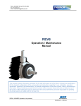
operation with an oscilloscope. Typical test point waveforms are shown in Figure 4.
Figure 4
WAVEFORMS MEASURED AT J8 WHILE READING BLANK 12 mm BOROSILICATE TUBE WITH 1 ml WATER
ONE REV OF FILTER WHEEL - 340 ms DURING READINGS
> 4 V
J8-3
FHOME
< 1 V
>4 V
J8-2
FCNT
< 1 V
< 10 V
MINIMUM PEAK HEIGHT 2V, MAX 10V
J8-5
2AP
> 2 V
Sample
< 30 m V
BASELINE HASH
Hold
340 nm
OPTIONAL
FILTERS
630 nm
580 nm
545 nm
505 nm
405 nm
Home
Service Manual HUMALYZER 2000
Page 7
-./90.=8*605./90
The internal printer is a 20-column thermal type device which prints ASCII characters
using a 5 x 7 dot matrix. There are no adjustments. However, a printer jam can occur if
the printer paper tears and becomes lodged in the printer mechanism, thus preventing
the print head from moving freely. If the instrument displays "Printer is jammed!", or if
the print head does not return to the home position, check for obstructions in the print
head path..
I$"@-<L
D1*.1/*=778E*=.E*;1049*/1*/>9*B>5/9*490=?54*705./*>9=2O*D1*.1/*:40=/4>*/>9
78=/9.*10*70E*B5/>*:>=07*1JP94/:Q*@>5:*B588*29:/01E*/>9*705./90O
Carefully remove any paper or debris with a pair of tweezers. Turn off the power
switch, wait 5 seconds, then turn on the power switch. The print head should move to
the right side and then return to home position at the left.
An alternate method of removing a particularly stubborn wad of paper is to move the
print head manually. To do this, remove the rear dress panel. Look at the front of the
printer mechanism. Locate the small gear on the right side which turns the grooved
steel print head shaft. Turn the gear so that the print head moves away from paper
wad and the paper can be easily removed. Turn the power switch off and back on
again as described above.
G9E7=2
The keypad is a sealed membrane switch layer which is not serviceable. You can test
the keypad by pressing $"R, then pressing all keys except I%($)*and (L@(). Note
that each key causes the instrument to beep and display a character. Press I%($)
and the display clears. Press (L@()*to end the test.
D5:78=E
The display is a 24 x 2 line super twisted nematic liquid crystal display module with
integral controller. The display should be clearly legible at all times, with no dark
spots or stray dots. There are no adjustments.
H905=8*610/
By using a special cable, a serial printer or computer with a serial port may be
connected. This is a male 9-pin DB-style connector using RS-232 signals in a nonstandard pinout. The data format is 2400 baud, 8 bits, 1 stop bit, and no parity.
The pinout for the serial port is:
1
2
3
4-9
GND
TX
RX/DTR
NC
Contact your distributor to obtain a serial printer cable.
Service Manual HUMALYZER 2000
Page 8
(0010*#9::=K9:
Error messages are displayed when the instrument fails to operate correctly. They are
intended to help the operator locate the problem. If error messages appear frequently,
a hardware problem is usually indicated.
The following error messages indicate possible interface or component problems.
Lamp Failure
The lamp does not appear to illuminated at all. Low
voltages were detected for all filter positions. See the
section "Photometer" under "Troubleshooting".
Lamp Output Low
The lamp does not appear to be illuminated
sufficiently. Low voltages were detected for some filter
positions. This is possibly due to degraded filters. See
the section "Photometer" under "Troubleshooting".
Printer Paper Jam
The internal printer paper path is obstructed. Clear
the paper path. If the paper path is clear, Check the
14-pin DIP cable connecting the printer PCB to the
interface PCB.
Printer Not Ready
The external printer attached to the parallel port or
serial port is out of paper or otherwise unable to print.
If chronic, this may indicate an incorrectly wired
external cable.
Waste is Full ! XX
The waste material has reached the level sensors. If
the waste bottle is empty, check the sensor cable,
jack, and internal wiring for shorts. On the pump
control PCB, check U2A, Q2 and U3. Check the cable
from the pump control PCB to the main PCB.
Empty Waste-Press Enter
See "Waste is Full !", above.
Filter Wheel Err
The instrument cannot correctly detect pulses from
the filter wheel. Check the photometer LED board and
the phototransistors Q12 and Q13 on the photometer
PCB. See the section "Photometer" under
"Troubleshooting".
Vacuum Leak
The self-check routine was unable to achieve vacuum
within the prescribed length of time. Check for leaks at
the waste bottle and at all connections.
Service Manual HUMALYZER 2000
Page 9
The following error messages indicate possible failure of the NV RAM U3, or the
address decoding logic at U6,U7, and U16. U3 can be checked by substitution.
**Memory Error**
The checksum failed when a stored test was recalled.
The test was deleted.
Filter Labels 7& 8 Clrd
The stored filter labels were corrupted or not found.
See the section "Restore Filter Labels".
Water Values Reset
The stored water absorbances were corrupted or not
found.
Do Temp Test 210!
The stored temperature calibration values were
corrupted or not found. See the section "Restore
Calibration".
Do ABS Test 212!
The stored absorbance calibration values were
corrupted or not found. See the section "Restore
Calibration".
Service Manual HUMALYZER 2000
Page 10
H90M549*601492309:
<79.5.K*/>9*-.:/03?9./
Refer to Figure 3., Instrument Interior. The cover is hinged at the rear panel, and can
be raised to allow access to the inside of the instrument. Disconnect the power cable,
the tubing, and the sensor lead from the rear panel. Move the instrument forward until
the front edge overhangs the work surface. Locate and remove the cover screw from
the underside of the front edge. Gently lift the front of the cover upward, taking care to
clear the incubation block and photometer. Prop the cover open with a suitable object.
Do not force the cover backwards. Damage to the cover or fittings may result.
Service Manual HUMALYZER 2000
Page 11
To reinstall the cover, reverse the procedure. Carefully lower the cover until it seats
on the chassis, taking care to clear the incubation block and the Luer fitting. Replace
the screw.
I89=.5.K*/>9*A81B4988
The flowcell should be cleaned when the instrument will not be used for an extended
period, e.g. overnight, end of shift, and when storing the flowcell. Proper cleaning will
help to prevent clogging of the flowcell tubing and valve tubing. Cleaning is extremely
important to obtaining accurate, repeatable results. If reagent, serum, or other
proteinaceous fluid is allowed to dry in the flowcell, it is extremely difficult to remove
and its presence can affect test results.
To clean the flowcell:
1.
Purge with air for at least 5 seconds.
2.
Aspirate several ml of flowcell cleaning solution. Allow the solution to
remain in the flowcell for 3 minutes.
3.
Aspirate 15 ml of distilled water then purge with air for 5 seconds.
4.
Aspirate 0.1N sodium hydroxide (NaOH ). Allow the solution to remain
in the flowcell for 3 minutes.
5.
Purge with air for at least 5 seconds.
6.
Aspirate 0.1N hydrochloric acid (HCl). Allow the solution to remain in
the flowcell for 3 minutes.
7.
Purge with at least 15 ml of deionized water.
8.
If the flowcell is to be removed for storage, purge with air until no
more fluid can be seen flowing into the waste bottle. Otherwise, leave
the flowcell filled with water.
Service Manual HUMALYZER 2000
Page 12
A81B4988*@3J5.K*)978=49?9./
The flowcell utilizes 1.2 mm I.D. Teflon tubing for the sample and exit tubes.
Replacement tubing is included with the tubing kit. Follow this procedure to replace
the flowcell tubing.
1.
Remove the flowcell. Unscrew the Luer and lift the flowcell out of the
read well.
2.
Remove the cover screws and lift off the upper flowcell cover.
3.
Refer to Figure 5-A. Disconnect the tube from the steel tube, then
remove the exit tube. Pull the exit tube out through the bulkhead.
Remove the cell insert screws and pull the cell insert and the sample
tube out. Remove the sample tube from the steel tube.
4.
Select the long or the short sample tube. The short sample tube must
be used when the sample volume is set to 350 µl or less. Carefully
press fit the end of the sample tube with the red dot (swaged end) to
the steel tube on the cell insert, and feed the other end upward
through the cell body. !5./S grasp the tubing with a small piece of
#400 grit emery paper. Do not kink the tubing. Refer to Figure 5-C for
the proper orientation. Do not reverse the orientation as improper
sampling will result. Install the cell body and screws.
5.
Feed the exit tube in through the rear of the flowcell. Press the exit
tube at least 7 mm to ensure a leak-free seal.
Figure 5-A
Service Manual HUMALYZER 2000
Page 13
Figure 5 - B
Figure 5 – C
Figure 5 – D
7MM
Service Manual HUMALYZER 2000
Page 14
A81B4988*$2P3:/?9./
The flowcell must be adjusted after replacing the flowcell tubing, or any time the cell
insert is removed or the adjustment set screw is disturbed.
1.
With the instrument on, lift the flowcell out of the read well. Do not
unscrew the fitting.
2.
Press #(L". Type 189 and press (L@(). The instrument will
continuously report the detector voltage at 405 nm. Record this value
for reference in the next step.
3.
Sample deionized water. Visually confirm there are no air bubbles in
the cell window.
4.
Insert the flowcell into the read well until it bottoms out. Note the value
displayed. If the displayed value is more than 50% greater than the
value you recorded in step 2, no adjustment is needed.
5.
If the displayed value is less than 50% greater than the value in step
2, Remove the flowcell. Adjust the set screw with the hex wrench
supplied. Turn the set screw 1/4 turn in either direction and go to step
4.
If the value in step 4 increases, turn the set screw in the same
direction. If it decreases, turn the setscrew in the opposite direction.
6.
Repeat steps 4 and 5 until the displayed value is at a maximum.
7.
When complete, press I%($)*twice to return to the main prompt. You
must read new water values as described in "Flowcell Configuration".
Service Manual HUMALYZER 2000
Page 15
A81B4988*D5:=::9?J8E
The flowcell may be disassembled for extensive cleaning or replacement of the cell
insert.
To replace the cell insert:
1.
Follow the procedure for Flowcell Tubing Replacement except install
a new cell insert before beginning step 6.
2.
Install the new cell insert in the same orientation as the old. Do not
force the new cell insert into the lower cell body. The part should slide
easily into place. If it does not fit easily, rotate the part 180°.
3.
Install the (2) #2-56 screws that attach the flowcell insert to the lower
cell body.
4.
Complete the procedure "Flowcell adjustment" to restore optical
alignment.
To completely disassemble the flowcell:
1.
Follow the procedure for Flowcell Tubing Replacement through step 3
2.
Remove (2) #2-56 screws holding the lower cell body and lift it off.
3.
Remove (2) #4-40 screws holding the upper cell body and separate it
from the cell bracket.
4.
Assembly is the reverse of this procedure. After assembly, complete
the procedure "Flowcell adjustment" to restore optical alignment.
Service Manual HUMALYZER 2000
Page 16
C=8M9*@3J5.K*)978=49?9./
The short length of silicone tubing used in the sampling valve may become clogged or
worn with age. A replacement is included in the tubing kit.
1.
Set the power switch to OFF (O). Open the instrument as described in
"Opening the instrument" . Refer to Figure 8-A. Locate the valve
behind and to the right of the photometer.
2.
Refer to Figure 8-B. Pull back the pinch bracket and remove the valve
tubing from the valve body.
3.
Disconnect the valve tubing from the fittings at both ends.
4.
Install the replacement tubing to the valve body in a similar manner.
Push the tubing over the tubing barbs until seated. Be especially
careful not to kink, stretch, or tension the tubing.
5.
Carefully lower the instrument cover and replace the screw.
Figure 8-A
Service Manual HUMALYZER 2000
Page 17
C=433?*$2P3:/?9./
To adjust the vacuum, you will need:
Reference vacuum gauge reading at least 18 cm Hg.
(2) 15 cm length of 3.1 mm ID flexible tubing
3.1 mm barbed "tee" fitting
1.
Disconnect the vacuum line (blue Luer fitting) at the rear panel. Open
the instrument.
2.
Refer to Figure 9-A. Connect the vacuum gauge as shown. Refer to
Figure 9-B. Locate the pump control PCB. Turn the trimpot on the
pump control PCB fully counterclockwise.
3.
Turn on the instrument. Press 6")T(* and wait until the vacuum
pump stops running. The vacuum gauge should read much less than
18 cm Hg. Slowly turn the trimpot clockwise until gauge reaches 17.8
cm Hg. When turning the trimpot, pause while the pump runs to
maintain vacuum.
4.
Set the power switch to OFF (O). Disconnect gauge and tubing.
Reconnect the waste bottle.
Figure 9 - A
From vacuum (blue)
fitting of instrument
Vacuum gauge,
18 cm Hg
To vacuum side
of waste bottle
Figure 9 - B
Service Manual HUMALYZER 2000
Page 18
Service Manual HUMALYZER 2000
Page 19
%=?7*0978=49?9./
Replace and/or adjust the lamp according the drawings below.
1. Photometer
2. Lamp removal/mounting
3. Adjustment screws
4. Lamp adjustment
5. Spot alignment at entrance slot
Service Manual HUMALYZER 2000
Page 20
A58/90*)978=49?9./
Materials/tools required:
¨ Replacement filter set
¨ Phillips screw driver
¨ Flat blade screw driver
¨ Silicone adhesive
1.
Open the instrument as described in "Opening the instrument". Refer
to Figure 3. Locate the photometer. Unplug both ribbon cables from
the main PCB.
2.
@>5:* 5:* =.* 5?710/=./* :/97* ;10* 09814=/5.K* 371.* 09=::9?J8E. Mark
with a pencil onto the chassis along the front and side edges of the
photometer subassembly.
3.
Locate the (3) #6 screws holding the photometer assembly to the
chassis. From the bottom of the instrument, remove these screws and
washer.
4.
Refer to Figure 11. Remove the (3) 6-32 screws retaining the
photometer cover. Set the photometer cover aside.
5.
Remove the (3) 4-40 screws securing the photometer PCB and gently
move it aside.
6.
Remove the filter wheel belt from the filter wheel and motor pulley.
Loosen the filter wheel shaft. Remove the shaft and filter wheel. Note
the number of nylon washers and the order of installation.
7.
Refer to Figure 12. Locate the filter to be removed. Push the filter out
of the wheel using the eraser end of a pencil or other soft blunt object.
Remove all filter components from that position in the wheel.
8.
Locate the neutral density filters, dot screen, and transmittance filters
that were included with the replacement filter and drop them first into
the cavity. Install the interference filter with the mirror side down.
Place (2) very small dabs of silicone adhesive on either side of the
filter to prevent it from working loose. Avoid smearing silicone
adhesive on the filter surface. Allow the adhesive to cure overnight.
9.
Install the filter wheel taking care not to pinch washers under the
shaft. Reassemble the shaft and washers as disassembled. Tighten
the shaft securely. The filter wheel should spin freely.
10.
Install the filter wheel belt. Be sure that the belt is centered on the
filter wheel and is not twisted.
11.
Install the photometer PCB taking care to center the board around the
shaft.
Service Manual HUMALYZER 2000
Page 21
12.
Replace the photometer cover, taking care to position the cable in the
slot of the cover. Do not pinch the cable under the cover. Tighten
cover screws only until snug. Do not over tighten the photometer
cover screws!
13.
Install the photometer subassembly to the chassis by replacing the (3)
#6 self tap screws through the chassis base. Line up photometer with
locating marks made in step 2. Connect the cables removed in step 1.
14.
Attach the power cord and connect the instrument to the mains
supply. Set the power switch to ON (1). Select test #186. The
displayed numbers represent the voltages of the installed filters. All
voltages should be between 2 and 11 volts.
Service Manual HUMALYZER 2000
Page 22
7
8
*)+$,-."/$
01'/($2-%"&'('")3
1
6
2
5
!"#$
%"&'('")
4
3
A58/90*%=J98
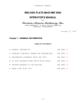
The filter label located on the photometer cover describes the specific filter wheel
configuration for your particular instrument. Refer to Figure 12.
Filter wheel position (POS) is the physical placement of the filter on the wheel. The
filter wheel position numbers are shown in the drawing.
Each filter position may have several filter elements installed. Filter configuration
(WAVELENGTH column) describes the various screens and filters in that position .
Each element is separated by a slash (/). The first 3 digit value in this column is
always the wavelength of the interference filter, in nanometers. The other values
indicate either dot screens, neutral density filters, or transmittance filters. A "D"
indicates a dot screen and the first two digits are the percent transmittance. For
example ,"90D" indicates a 90% dot screen. A 3 digit value (other than the first value
in the line) indicates a transmittance filter. The first digit is the quantity; the last two
digits are the percent transmittance. For example, "115" indicates (1) 15%
transmittance filter. A 2 digit value separated by a decimal point indicates a neutral
density filter. The value is the absolute absorbance of the filter. "BLOCKED" indicates
an opaque disk is installed in that position.
Manufacturer lot number (LOT#) is the interference filter manufacturers' production
code. The percent transmittance of the interference filter is also specified in this
column.
The production date (DATE) is the date the filter wheel was assembled.
POS
1
2
3
4
5
6
7
WAVELENGTH
340
BLOCKED
BLOCKED
630/90D/115/170
580/90D/115/170
545/215
505/215/15D
Service Manual HUMALYZER 2000
LOT#
DATE
3YGF 58.8% 5/23/94
5/23/94
5/23/94
4GDB 80.6% 5/23/94
3ZCJ 65%
5/23/94
3WEF 74.4% 5/23/94
4FLR 67.6% 5/23/94
Page 23
8
405/115/90D
Service Manual HUMALYZER 2000
4HDL 83%
5/23/94
Page 24
I=85J0=/51.
This instrument relies on software calibration, that is, on calibration data stored in
non-volatile RAM. This data is used by the microprocessor to compensate for
variations in electronic components and manufacturing. During factory calibration, the
calibration data is set and any hardware adjustments are made using precision
reference standards. The calibration data is then recorded on a label located on the
bottom of the instrument. The factory calibration is very stable and does not drift
appreciably over time, making trimpot or other component adjustments unnecessary
unless the trimpots are disturbed or calibration-related components replaced.
Recalibration of the instrument, software or otherwise, should not be considered until
all possible interfering factors have been ruled out. If field calibration is in fact
necessary, it should only be performed with the proper reference materials and
instruments. In any case, software calibration should be attempted before any trimpot
or component replacements or adjustments are considered.
The temperature calibration data is stored as offsets which the instrument adds to the
sensed temperatures. Separate offsets are maintained for the incubation block and
the read well. The absorbance calibration data is stored as a scaling factor, which is
the ratio of a known reference absorbance to the instrument's reported absorbance.
The calibration data may be printed at any time by selecting test #213. This prints the
serial number of the instrument, the date of last calibration, and the stored calibration
data for the absorbance, block temperature, and cell temperature.
The calibration data is stored with a check sum that is recalculated and compared
each time a mode is selected. Failure to recover the calibration data properly
(checksum failure) will be indicated on the display and the internal printer:
Do Temp Test 210!
Do Abs Test 212!
The instrument annunciates this condition with multiple beeps. The temperature
offsets for both the incubation block and the read well are then set to 0.0 and the
absorbance scaling factor is set to 1.000. In this condition, the maximum temperature
error is +/-1.5 _C and the maximum absorbance error is +/-10%. The calibration data
can be restored as described in "Restore calibration".
The hardware calibration of the instrument in time is based on a 2 MHz ceramic
resonator RES1. Calibration in temperature is based on C24, a 0.068µf polystyrene
capacitor, trimpots TP4 and TP5, and time. Calibration of absorbance is based on
C16, a 0.1µf polystyrene capacitor, trimpots TP2 and TP3, and time.
Service Manual HUMALYZER 2000
Page 25
I=85J0=/51.*=.2*$J:10J=.49*%5.9=05/E
Each instrument is calibrated during manufacturing using standards that are traceable
to the National Institute for Standards and Testing (NIST), and is tested to verify its
linearity to 2A. This preset calibration is very stable. Absolute calibration can be
verified with the use of NIST filters, or by periodic comparison to a reference
instrument that is known to be calibrated to NIST filters. Calibration may be confirmed
using a commercially available calibration check set which can be obtained from your
distributor. A periodic verification of instrument linearity is advised. Since most lab test
results are based upon standards rather than upon absolute absorbances, the
linearity of the instrument is the more critical indicator of instrument performance.
CAUTION
D<*L<@*$%@()*$L&*6<@(L@-<#(@()*H(@@-LTH*O
I>=.K5.K*/>9:9*:9//5.K:*B588*?=U9*/>9*;=4/10E*4=85J0=/51.*2=/=*5.M=852Q
-.*/>9*3.85U98E*9M9./*/>9*4=85J0=/51.*2=/=*5:*81:/*10*410037/92F*/>9
=J:10J=.49*;=4/10*5:*:9/*/1*VQ,,,*=.2*/>9*/9?790=/309*1;;:9/*=2P3:/?9./:
;10*/>9*J814U*=.2*4988*=09*:9/*/1*,Q,Q
D1*.1/*9./90*M=839:*1/>90*/>=.*/>1:9*09410292*1.*/>9*4=85J0=/51.*8=J98
3.89::*=J:183/98E*.949::=0EQ
Service Manual HUMALYZER 2000
Page 26
)9:/109*I=85J0=/51.*D=/=
Each unit is electronically calibrated at the factory. The calibration values are entered
by the keyboard and stored in non-volatile memory.
Do ABS Set Test 212!
Do Temp Set Test 210!
If either of these messages are printed or displayed, it indicates that the calibration
values have been lost. These messages will be printed each time that you turn on the
instrument, select a mode, or recall a test. The instrument will continue to operate, but
the calibration must be restored to ensure the accuracy of the instrument.
Follow these steps to restore the electronic calibration:
1.
Shut off the instrument. Remove any tubes or cuvettes from the
incubation block and read well. Carefully lift up the instrument and
locate the Calibration Data label on the underside of the unit. There
are three values recorded there: Absorbance, Block Temp, and Cell
Temp. Write down these numbers.
2.
Set the power switch to ON (1).
3.
If the date and time are incorrect, set the correct date and time. Press
@-#(*then press (D-@. Enter the date and time as prompted.
4.
Press #(L", type in 210, and press (L@(). When the display
shows "Block=", enter the number that is recorded under the Block
Temp heading on the calibration label. For example "0.3" or "-0.2" and
then press (L@().
5.
The display will prompt "Cell=". Enter the data from the Cell Temp line
of the calibration label.
6.
Press #(L", type in 212, and press (L@(). When the display
shows "Abs Factor=" enter the number from the Absorbance line of
the calibration label. If the message Adjust Out of Range is displayed,
check your values and repeat this step.
7.
Press #(L", type in 213, and press (L@()* to get a report of the
calibration data. The block and cell temperature adjust will be printed
along with the absorbance adjustment. Make sure that these values
are the same as those recorded on the calibration label.
Service Manual HUMALYZER 2000
Page 27
)9:/109*A58/90*%=J98:
Like the calibration data, the wavelengths for the two optional filters are stored in nonvolatile memory. In the event this data is lost or corrupted, the following message will
be displayed and printed.
Filter Labels 7&8 Clrd!
You will need to re-enter the filter labels for two of the filters. Open the instrument and
locate the filter label on the side of the photometer cover.
Key 7 is xxx
Key 8 is xxx
"xxx" is a three-digit wavelength value. Press #(L", type in 248, and press (L@().
You will be prompted:
Change Filter Names
Key 7 = ??? nm
Type in the wavelength for Key 7 that is printed on the label and press (L@().
Repeat for Key 8. Press I%($)*twice to return to the main prompt.
Service Manual HUMALYZER 2000
Page 28
@9?790=/309*I=85J0=/51.
Materials and equipment:
¨
12 mm borosilicate tube
¨
Reference thermistor probe
YSI Inc. #44108 or equivalent.
30K @ 25°C,± 0.2° interchangeability
¨
Humalyzer 2000 Temperature Calibration Fixture
¨
Digital ohmmeter (DMM), 0.5% or better accuracy.
1.
Ensure that the flowcell is active. Press CELL. Press YES to activate
the flowcell. Press CLEAR twice to revert to the temperature display.
2.
Place a 12 mm borosilicate test tube filled with 1 ml of water into the
incubation block. Use a station near the center of the block. Suspend
the reference thermistor probe in the approximate center of the tube.
3.
Remove the flowcell and install the Temperature Calibration Fixture
into the read well.
4.
Allow 15 minutes for equilibration.
5.
Set the DMM to read 20K. Read the resistance of the thermistor and
the fixture. If the resistance is between VWW+X* Y and VZWV+* [, no
adjustments are needed. Otherwise, continue to the next step.
6.
Calculate the temperature offsets using the following formula:
T = R - 18210
C
7.
Where:
R is the measured resistance.
C is equal to 750 if the measured resistance is
greater 18210.
C is equal to 720 if the measured resistance is
less 18210.
Select test #210. The display shows:
Block adjust=
Type the offset calculated above for the block and press ENTER.
8.
The display shows:
Cell adjust=
Type the offset calculated for the cell and press ENTER. The
maximum allowed adjustment is +/-1.8_C . Entering values that
exceed this net number will produce an out of range message.
9.
Repeat steps 4 through 8 until the temperature is 37°C ± 0.3.
10.
Select test #213 to see the current net adjustments. Record the new
values on the calibration label located on the bottom of the
instrument.
Service Manual HUMALYZER 2000
Page 29
$J:10J=.49*I=85J0=/51.
Materials and equipment:
¨
12 mm borosilicate tube
¨
Reference spectrophotometer
¨
Reference material which peaks at one of the instrument's
wavelengths.
¨
Precise 1:2 serial dilution of the reference material.
1.
Ensure that the flowcell is active. Press I(%%. Press &(H*to activate
the flowcell. Press I%($)*twice to revert to the temperature display.
2.
Place a 12 mm borosilicate test tube filled with 1 ml of water into the
read well.
3.
Select test #186 and confirm that all of the filter voltages are between
2.00 and 11.00 volts.
4.
Determine the absorbance of both the 1:1 reference material and the
1:2 dilution on a reference spectrophotometer. The 1:2 dilution should
be in the range of .8 to 1.2 absorbance. The 1:1 material should be in
the range of 1.6 to 2.4 absorbance.
5.
Press ABS to place the instrument into the absorbance mode. Select
the required wavelengths. Blank on the same diluent material used to
prepare the concentrations.
6.
Read the 1:2 dilution. Divide the absorbance as read on the reference
spectrophotometer by the reported absorbance value.
7.
Exit the absorbance mode and select test #212. At the prompt
"Absorbance factor= x.xxx?", enter the ratio calculated. When this
factor is entered the instrument will display a net factor (the new
calibration data).
8.
Press I%($)* twice and restart the absorbance mode. Blank as
before on the diluent. The 1:2 dilution absorbance should now agree
with the reference to within +/-.005 absorbance.
9.
Read the 1:1 concentration. It should agree within +/-2 % of the
reference. If necessary, carefully adjust trimpot TP3 to achieve this
agreement. Re-blank and reconfirm the values.
10.
Select test #213 to print the new calibration data. Enter these values
on the calibration data label on the bottom of the instrument.
Service Manual HUMALYZER 2000
Page 30
H7945;54=/51.:
Specification Date
31 May, 1994
Model Name
Humalyzer 2000, Cat. No. 18300
Spectrophotometer Type
Filter photometer
Optical Configuration
Single beam with continuously rotating filter
wheel Monochromatic or bichromatic reading 8
filter positions
Usable Spectral Range
330 to 700 nm
System Procedures Open and by stored menu
Calculating Modes
Absorbance
Single Standard
Differential samples
Factor Mode
Differential samples
Multi Standard Mode (7 standards)
Multi Standard % Abs (7 standards)
Kinetic Mode
By Factor or by Standard
Fixed Time Kinetic
By Factor or by Standard
Channels
44 fixed, 24 open
Source of RadiationTungsten Halogen, 10 Watt, with automatic lamp saver
Selection of Wavelength
By filter
Filter Type
Half Bandwidth
1/100 Bandwidth
False Radiant Energy Ratio
4-cavity interference, long-life ion beamassisted deposition
+/- 3 nm
After sample (heat filter before sample)
Automatic by software or via keyboard
340, 405, 505, 545, 580, 630 nm supplied
standard other/additional filters optional
< 10 nm
14 nm at 340 nm
< 0.001 at 340 and 405 nm
Type
Material
Geometry
Illuminated Volume
Minimum Read Volume
Flow-through
316 stainless, borosilicate windows
Cylindrical, 2.3 mm dia x 5 mm +/- 0.05 mm
21 µL
250 µL
Wavelength Accuracy
Filter Location
Filter Selection
Wavelengths
Cuvette
Service Manual HUMALYZER 2000
Page 31
Aspiration/Purge Valve
Vacuum pump at 18 cm of Hg
Silicone pinch type
Other Vessels
12 mm test tubes
1 cm square cuvettes
Cuvette Holder
Thermostatically controlled compartment at 37° C
Detector
Gallium-Arsenide-Phosphide photodiode
Signal Processing and Display
Display Type
2 line x 24 character super twist LCD
Scale of Display
Absorbance
Concentration
Kinetic Results
-0.5 to 3.5 (flow-through mode)
-0.5 to 2.5 (tube or 1 cm cuvette)
Maximum 999,999
Abs/min with resolution of 0.0002 A/min
Zero Compensation
Range
Automatic
-0.5 to 2.0 absorbance
Signal Outputs
Parallel
Serial
Centronics/IBM-PC compatible
RS-232 at 2400 baud, 8 data, 1 stop, no parity
Spectrophotometric Inaccuracy
Flow-through
< 0.5% at 1 absorbance, 340/630 nm NADH solution
< 1% at 2 absorbance, 340/630 nm NADH solution
< 3 % at 3 absorbance , 340/630 nm NADH solution
< 0.5 % at 1 absorbance, 405/630 nm PNP solution
< 1 % at 2 absorbance, 405/630 nm PNP solution
< 3 % at 3 absorbance, 405/630 nm PNP solution
Stability
Better than 0.003 A/hr monochromatic after warm-up
Better than 0.001 A/hr bichromatic after warm-up
Warm-up Time
90 seconds photometric
15 minutes for temperature compartment
Electronics
Z80 microprocessor
8 K bytes Static RAM (SRAM)
8 K bytes non-volatile RAM (NVRAM)
Power Supply
115/230 VAC, 50/60 Hz, +/- 10%, 60 VA
Dimensions and Weight
35 x 40 x 15 cm, 10 Kg
Space Requirements
10 cm clearance on all sides
Service Manual HUMALYZER 2000
Page 32
)978=49?9./*6=0/:
See Figures 13-15 for illustrations.
Item
1.
2.
3.
4.
5.
6.
7.
8.
9.
10.
11.
12.
13.
14.
15.
16.
17.
18.
19.
20.
21.
22.
23.
24.
Description
Lamp
Fuse
Printer paper
Keypad (domed)
Overlay with keypads
Main PCB
Interface PCB
Display (LCD)
Photometer assembly
Incubation block assembly
Cover assembly
Fan
Filter wheel belt
NV RAM (battery-backed)
Printer mechanism
Printer interface PCB
Pump control PCB
Valve assembly
Waste bottle assembly, 500 ml
Internal cable set
Vacuum pump
Tubing kit
Exhaust filter
Cell insert
Cat #
18340/05
18340/10
18310/05
18380/05
18380/10
18350/05
18350/10
18340/25
18370/05
18340/35
18380/20
18340/30
18380/05
18340/15
18360/15
18350/15
18350/20
18360/10
18320/05
18340/20
18340/40
18320/10
18320/15
18370/10
25.
Replacement filters
340 nm
405 nm
505 nm
545 nm
580 nm
630 nm
Special filters
18330/30
18330/05
18330/10
18330/15
18330/20
18330/25
(Specify)
Service Manual HUMALYZER 2000
Page 33
VV
&(H STND
V
RATE
+
FACT
_
Lamp
STORE
EDIT
DEL
TEMP
ABS
X
PGM
b
%ABS
a
Paper
CELL
VOL
FILT
UNITS
DATA
W
AUX
Z
Clear
SelfCk
]
TIME
(L@()
#(L"
X
L< BLANK
,
+,,,
.
`
\
PRNT
S
PURGE
^
)($D
b
V
+
V
_
+X
V`
+_
Service Manual HUMALYZER 2000
Page 34
+V
VX
Z
a
`
V_
W
V,
+b
VZ
VW
Vb
V+
Va
Service Manual HUMALYZER 2000
Page 35
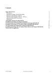
D5=K0=?:
N814U*D5=K0=?
6IN*%=E13/:
#=5.*6IN
63?7*I1./018*6IN
-./90;=49*6IN
605./90*6IN
-.43J=/51.*J814U*6IN
605./90*6IN
-.43J=/51.*J814U*6IN
H4>9?=/54:
#=5.*6IN
63?7*I1./018*6IN
-./90;=49*6IN
605./90*6IN
-.43J=/51.*J814U*6IN
Service Manual HUMALYZER 2000
Page 36
Service Manual HUMALYZER 2000
DETACHABLE
LINE CORD SVT TYPE
LINE CORD
RECEPTACLE
READ CELL
INCUBATION BLOCK
.
BN
FB-1
BU
FB-3
4
L
CELL
HEAT
ELEMENTS
GRN/YEL
E
GROUND
N
2
2
2
AC POWER
GRN/YEL
SOLDER LUG
OPTICAL
TUBE DETECT
SWITCH
CELL
THERMISTOR
LCR1
LC1
LAMP
5 VOLT
#6 SOLDER LUG
PHOTO
AMPLIFIER
FAN
12 V
+15 VOLT
-15 VOLT
+5 VOLT
2
BRN
BLU
2
2
LED
PCB
4
TRANSFORMER
GT9725 or
300-06C
SWITCHED MAINS
TO HEAT BLOCK
PRIMARY WINDINGS
TF1,TF2 THERMAL
FUSE 218 F
ANTI-ROTATION
2
4
PHOTOMETER ASSEMBLY
SECONDARY WINDINGS
T1
FUSE BLOCK
@115VAC,BUSS
FUSEMDL-1/2
DPST SWITCH
260011E
VOLTAGE SELECT SWITCH
SW1
SW2
BLK
No.1
TF1
10
14
No.1
FB
FB-1
BRN
12
11
BRN
BLK/WHT
FB-2
No.2
1
FB-3
ANALOG TO
DIGITAL CONVERTER
+/-15 VOLTS
GRN
FU
6H
6
GRN/YEL
FB-4
TF2
BRN
FU
4H
GRN
25
24
BLU
2
5
BLU
No.2
3
4
115 VAC OPERATION SHOWN
2H
BLU
FOR 115/230 VAC MAINS OPERATION
BRN/WHT
CAUTION- DO NOT CHANGE SETTING
WITH POWER APPLIED. FOLLOW THESE STEPS:
UNPLUG UNIT FROM MAINS POWER; CHANGE FUSE;
SET SWITCH; REPLUG UNIT INTO MAINS POWER.
18 VAC
TO +15 VDC.
5
GRN
GRN/YEL
TYPE 2 LIMITED
SECONDARIES
TEST
POINTS
4
GRN
3
BLU
11 VAC
TO +12 VDC AND
(2)+5 VDC.
2
BLU
1
SERIAL PORT DRIVER
+/- 15 VOLTS
26H
FULL
SENSOR
VALVE ASSY
PUMP
9H
18 VAC
TO -15 VDC.
6
SENSOR
BOARD
MAIN PCB
TYPE 2 LIMITED
POWER SUPPLY
TB2
No.3
TRANSFORMER: ELECTROSTATIC SHIELD
GROUNDED TO FRAME AND CHASSIS
PART GT9725 ONLY. NO SHIELD ON
PART 300-06C (SPLIT BOBBIN TYPE).
FLOWCELL
Z80
MICROCOMPUTER
+5 VOLT
4H
2H
2
PRINTER
POWER
26
4
2
VACUUM
TO EXT WASTE
BOTTLE
LED DISPLAY
+5 VOLTS
WASTE
INTERFACE PCB
14
PRINTER
INTFC PCB
14H
FRONT PANEL SUBASSEMBLY
14
Page 37
4
PARALLEL
PORT
8
8
25
SAMPLE SW
READY LED
4x4
4x4
KEYPAD
8
KEYPAD
8
SERIAL PORT
Service Manual HUMALYZER 2000
Page 38
Service Manual HUMALYZER 2000
Page 39
Service Manual HUMALYZER 2000
Page 40
Service Manual HUMALYZER 2000
Page 41
Service Manual HUMALYZER 2000
Page 42
Service Manual HUMALYZER 2000
Page 43
Service Manual HUMALYZER 2000
Page 44
Service Manual HUMALYZER 2000
Page 45
Service Manual HUMALYZER 2000
Page 46
Service Manual HUMALYZER 2000
Page 47
Service Manual HUMALYZER 2000
Page 48
Service Manual HUMALYZER 2000
Page 49
Service Manual HUMALYZER 2000
Page 50
Service Manual HUMALYZER 2000
Page 51
Human
Gesellschaft für Biochemica
und Diagnostica mbH
Max-Planck-Ring 21 ! D-65205 Wiesbaden
Germany
Telefon:
+49 6122 9988 0
Telefax:
+49 6122 9988 100
eMail:
Internet:
01/2004-04
[email protected]
http://www.human.de