1
7
4,899,292
and the opposite side edge is grounded. Wand or stylus
130 is connected to the input of an A/D converter (not
shown). The touch screen is resistive so that the voltage
at the point of touch corresponds to the location be
tween the aforesaid side edges. Next, the voltage is
applied to one of the other perpendicular side edges and
the opposite side edge is grounded to determine the
location between these two side edges. Software previ
ously loaded into PROM 50 from either CD-ROM 24
or floppy disk 48 controls this decoding operation. The
8
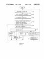
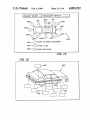
After selecting from this menu by touch-screen 70,
either menu 204, 205 or 206 is displayed. After selecting
from one of the latter menus, a document such as the
one including hyperpage 28, graphics 31-33 and data
table 34 de?ning the selected repair procedure is identi
?ed (step 108).
In addition to utilizing the menus 200 and 204-206
illustrated in FIG. 3, microprocessor 60 is optionally
programmed to read in step 108 key words to locate one
or more hyperpages which contain some or all of the
decoded information is transmitted to microprocessor
60 via bus 65. Thus, the user can make selections and
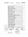
key words. The key words may be input through a
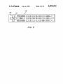
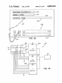
keyboard 500 which is displayed on screen 23 as illus
commands relating to text, worksheets, graphics and
trated in FIG. 16. To display keyboard 500, data de?n
data displayed on screen 23 by either keypad 74 or
ing keyboard 500 and worksheet 501 was downloaded
touch screen 70.
15 from CD-ROM 24 into DRAM 22 at the time that the
A static random access memory (SRAM) 78 stores
document was identified. To utilize the keyboard 500,
calibration constants representing the alignment of the
?rst one of selection boxes 502, 503 or 504 is selected by
touch screen relative to the display screen and other
a touch with stylus or wand 130. To permit keyboard to
information described below.
?t on the screen, the normal distance between adjacent
An electronic clock and calendar module 80 is also
rows of lettering may be reduced by eliminating one or
provided to assist system 20 in generating reports. A
more of the intervening blank raster lines. Microproces
parallel data port 81 provides communication with a
sor 60 reads the location of the touch from interface 76,
printer and serial data ports 82 provide communication
and based on decoding software stored within PROM
with a central computer 437 via a modem 89.
50 correlates the touch with the category within the box
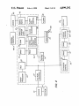
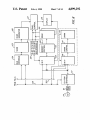
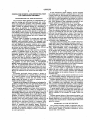
Communication channels between the foregoing ele 25 in order to read and display the information in each
ments of system 20 are illustrated in more detail in FIG.
category. For example, as illustrated by broken-line in
6, along with additional related components. To trans
FIG. 16, the user touched box 504 after completing
mit data, microprocessor 60 transmits via lines 300 an
boxes 502 and 503. After touching box 504, micro
address of the destination component to bus controller
processor 60 is programmed to display the subsequent
65 and latch 302. Microprocessor 60 also transmits the 30 letters in box 504 and to treat the letters as one or more
data via lines 304 to buffer 306, and a write command
key words. Then the user successively touched letters
via line 310 to bus 65. An address decoder 312 transmits
“C”, “A”, “R” and “B” to begin spelling the ?rst key
corresponding enable signals to the destination compo
word “carburetor.” The user may then enter the re
nent via lines 314. Then the destination component
mainder of the key word “carburetor”, and other key
reads the address at which the data should be stored
from latch 302 via bus or lines 318 and then reads the
data from buffer 306 via bus or lines 320.
and “poor acceleration” in order to access a procedure
To read data, microprocessor 60 transmits the ad
words such as, “Cadillac”, “V-8/450HP”, “fast idle”
for making the necessary repair. Thus, this indexing
scheme diagnoses the problem as well as accesses tex
dress of the source component to bus controller 65 and
tual and graphic information necessary to make the
latch 302, and a read command on line 310 to bus con 40 repair. As further illustrated in FIG. 16, keyboard 500
troller 65. In response, address decoder 312 transmits
was previously used to enter the name of the repair shop
corresponding enable signals to the source component
by touch of box 502 followed by touch of the letter
via lines 314. Next, the source component reads the
boxes on keyboard 500 which spell the repair shop
address at which the data should be read from latch 302
“ACE REPAIR CO.”. Similarly, the name of the
via lines 318, and then transmits the data into buffer 306 45 owner of the vehicle “I. JONES” was also entered by
via lines 320. Microprocessor 60 reads the data from
touch of box 503 and then boxes on keypad 500.
buffer 306.
.
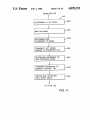
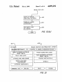
Referring to FIGS. 7 and 8, after the document selec
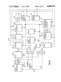
FIG. 4 also illustrates an image decompression board
tion, microprocessor 60 transmits a sector address to
95 comprising a dedicated processor 96 and an associ
CD-ROM interface 67 via bus 320 to locate the selected
ated DRAM 97 providing work space for the decom
document, and afterwards reads all the reference num
pression process. By way of example, board 95 is a
bers within the document identifying all the graphic
Model TMS-340l0 manufactured by Texas Instruments
images within the selected document (step 109). Then
of USA. As described in more detail below, with refer
CD~ROM reader 63 accesses the graphic information
ence to FIG. 7, decompression board 95 decompresses
under the control of processor 60, which processor then
the graphic image data stored on CD-ROM 24 or 55 extracts header information de?ning the size of the
?oppy disk 48, and transmits the decompressed data to
image and each region on the screen 23 which forms a
a DRAM 99 for storage within a graphics controller
touch pad as described in more detail below. The
board 100. In the decompressed form, data defining
header information is stored in DRAM 72. Then, in step
each pixel for the screen provides a one-to-one mapping
110, decompression processor 96 reads the compressed
and capability for instantaneous display. A graphics 60 graphic data of the selected document from CD-ROM
controller processor 102 on board 100 controls the
20 via interface 67 and decompresses the data with the
transfer of the decompressed graphics data to screen 23.
aid of workspace DRAM 97 and DRAM controller
FIG. 7 is a flow chart illustrating the utilization of
114. Then, processor 96 transmits the decompressed
system 20 is an electronic service manual application.
graphic image data to graphic control processor 102 for
However, it should be understood that system 20 can be 65 storage in DRAM 99 with the aid of memory control
programmed to implement a wide variety of processes.
116. Memory control presents the addresses specified
Initially, a user may request via keypad 74 the menu 200
by microprocessor 102 to DRAM 99 in two parts in two
different cycles. One part specifies a column and the
of repair procedures contained within CDLROM 24.