1
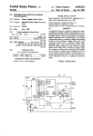
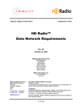
llllllllllllllllllllllllllllllllllllllllllllllllllllIllllllllllllllllllllll
US005187352A
United States Patent [191
[11]
[45]
Blair et al.
[54] MICROPROCESSOR CONTROLLED
Patent Number: _
Date of Patent:
5,187,352
Feb. 16, 1993
SECURITY SYSTEM FOR COMPUTERS
Apple Computer Inc., AppleTalk Personal Network,
Disclosure, Apr. 1986.
[76] Inventors: William Blair, 1154 W. Lunt, Apt.
302, Chicago, Ill. 60626; Stanley J.
Brooks, PO. Box 906, Douglas, Ga.
Sun Micro Systems, Tech Note 1010, Network Hard
ware and Cabling Topologies, Aug. 1989, pp. 1-6.
Sun Micro Systems, Tech Note 1011, Cabling with
TOPS and Ethernet, Aug, 1989, pp. l-2.
31533
Centrams Systems West, Inc., Manual, 1987.
Recommac Corp., New Product Release, Model Ver
sions v. H21, Dec. 18, 1989, pp. l—-4.
Recommac Corp., New Product Release, Model Ver
[21] Appl. No.: 597,422
Oct. 15, 1990
1221 Filed:
sions vHl.0.1 and Model Versions vl-l2.l, Sep. 19, 1989.
Recommac Corp., Brochure, Jun. 6, 1990.
Recommac Corp, Brochure, Aug. 12, 1990.
Motorola, Microprocessor, Microcontroller and Pe
Related US. Application Data '
[63]
Continuation-impart of Ser. No. 297,302, Jan. 3, 1989,
abandoned.
[51]
[52]
Int. Cl.5 ............................................. .. G06K 5/00
[58]
Field of Search ................... .. 235/382, 382.5, 487;
ripheral Data Book; MC68701U4 technical disclosure;
MC68701 technical disclosure; MC6801 and MC6803
technical disclosures (1988).
Primary Examiner-Harold Pitts
Attorney, Agent, or Firm-Allegretti & Witcoff, Ltd.
US. Cl. ............................... .. 235/382; 235/382.5;
235/487; 380/25
340/825.3l; 902/22; 380/25
[56]
[57]
ABSTRACT
A microprocessor controlled computer security system
References Cited
U.S. PATENT DOCUMENTS
3,896,266
4,800,590
7/1975 Waterbury .
l/l989 Vaughan .
4,839,640
l/l989
is disclosed that provides for controlled access to single
or multiple components of a computer system. The
security system includes a magnetic card reading and
encoding device that reads component access and time
Ozer et al. ........................ .. 235/382
OTHER PUBLICATIONS
allotment data from a magnetically encoded card. A
George Sadowsky, A Proposed Plan for Academic
Computing, Spring 1989, pp. 2-13.
Byte Magazine, L. Brett Glass, Part 1 The SCSI Bus,
Feb. 1990, pp. 267, 268, 270, 271, 272, 274.
Byte Magazine, L. Brett Glass, Part 2 The SCSI Bus,
microcontroller, which incorporates a microprocessor,
processes the data read by the reading and encoding
device and responsively issues enable or disable signals
through a component interface circuit to the computer
system component or components to be enabled or
disabled. The components to be enabled may be the
video display device, hard disk drive, or external cen
Mar. 1990, pp. 291-296.
POWER R, Video Products and Price Information,
tral processing units of slave computers. The security
system further includes audio and visual indicators that
provide system and component status information. The
Aug. 1988.
Xico, lnc., Magnetic Stripe Card Terminal Data Sheet
and Instruction Manual, Jun. 1986.
magnetic card reading and encoding device is operable
Xico, Inc., Drawings, Jan. 25, 1985.
in a program mode, wherein the magnetic card is pro
grammed with component access and time data, and a
Xico, Inc., Model 2165 RS-232C Controller For Series
6500 Swipe Reader/Encoders User’s Manual, Mar.
1986.
Mac Users Magazine, Kurt VanderSluis, The Exorcist,
Part II, May 1989, pp. 230, 232.
reading mode wherein the reading and encoding device
reads and updates the access and time data on the card.
26 Claims, 5 Drawing Sheets
LEOS
322
/4
70
CARD
RUDE“
ENCODER
'6
1
Power:
menace
L
46
‘8/
mocessoa
22
24
/8~/
\g
PERIPHERAL
25
\CRVS‘TAL
\.
m
1
z”
"mam
8
Nil/DR /30
EXTERNAL
WITORS
'1
-—
@mm
‘86
'2
4/
AUDIO
imam:
mu
ROM
'3‘ if
US. Patent
Feb. 16, 1993
Sheet 2 of 5
5,187,352
'3PCSLAVE
1
5,187,352
2
Computer-owning institutions could, of course, place
MICROPROCESSOR CONTROLLED SECURITY
SYSTEM FOR COMPUTERS
each computer within a locked'room (with different
rooms having different combinations of peripherals)
and allow students or other users access to those rooms
only for limited and carefully controlled times. How
5
This is a continuation-in-part of application Ser. No.
297,302, ?led Jan. 13, 1989, and now abandoned.
ever, a simple locked room is often inadequate to pro
vide proper security for personal computer data and
BACKGROUND OF THE INVENTION
makes accurate accounting of the individuals who use
computers and their peripherals, and the amount of use
A portion of the disclosure of this patent document
contains material which is subject to copyright protec 0 by each individual difficult. Such methods are cumber
tion. The copyright owner has no objection to the fac
simile reproduction by any one of the patent disclosure,
as it appears in the Patent and Trademark Office patent
?les or records, but otherwise reserves all copyright
rights whatsoever.
A. Field of the Invention
The present invention relates generally to a micro
processor controlled security system for computers,
especially personal computers. More particularly, it
relates to a computer security system accessed by mag
netically encoded cards that allows control of personal
computer access and time usage, internally recorded
data and attached peripheral devices.
B. Description of Related Art
With personal computers and their applications be
coming more commonplace, an increasing number of
such computers are being placed in multi-user environ
ments. For example, universities and other educational
some and, in any event, unlikely to be followed with the
consistency necessary for accurate accounting or cost
charging.
Another potential multi-use circumstance for per
sonal computers is in a classroom environment, where
one “master" computer, associated with an instructor,
displays its data on the screens of a number of “slave”
computers, each associated with one or more students.
These screens and their internal hard drives can also be
driven-by the “master computer” independent of indi
vidual computers. In that circumstances, the instructor
often wants control over the activation of the individual
computers or screens so as to fully control the lecture or
other educational environment. Aside from physically
disabling the “slave” computers, hard drives, or screens
by, for example, disconnecting the equipment from its
power source, few methods have been traditionally
available for allowing instructors to have such control.
Due to the need for security for personal computer
institutions often give their students access to many
systems, it is not surprising that considerable effort has
personal computers, and allow the same computer to be
been made in the prior art to meet the needs of comput
used by any of a number of different students. Typi~
er-owning institutions. Simple password techniques are
cally, a university or other institution might make per
perhaps the most familiar, where access is gained by the
sonal computers available in a library for the use of
user by entering a password into the computer. Pass
students who are studying or conducting research.
35 word generating machines combined with computer
Similarly, businesses will often make one or more
interfacing devices are also known int he art, one exam
personal computers available for use by multiple em
ployees, who perform the same or similar tasks, or who
may even perform dramatically different tasks. In either
circumstance, the computer may have any of a variety
of built-in or peripheral features, such as disk drives
ple being U.S. Pat. No. 4,800,590 issued to Vaughn.
Other security techniques include call and call back
systems, security by encoding messages and data, and
“trapdoor” encryption schemes. However, such com
puter access and security techniques each have their
(?oppy disks, hard disks, CD ROM’s, etc), printers,
limitations. Most do not provide for limited time access,
and some are too expensive or impractical for personal
vices, or video devices.
computers or personal computer networks. Addition
When personal computers are made available for use 45 ally, many prior art methods are not suitable for selec
by multiple individuals, the organization owning the
tive access to peripheral devices linked together
optical scanners, modems, FAX machines, MIDI de
computer often wants to maintain control of the access
to those computers, and their peripherals. Thus, educa
tional institutions and businesses may keep their per
sonal computers within locked rooms and allow entry
into the room only by those with authorization to access
through a peripheral data bus to a master computer.
Accordingly, it is an object of this invention to pro
vide a system for controlling access to personal com
puter and peripheral devices to authorized users.
It is also an object of this invention to provide a com
puter security system that is suitable for personal com
puters, and that is both practical and of reasonable cost.
A further object of this invention is to provide secu
often seek to allocate the expenses for each computer’s
use, either in the organization’s accounting procedures 55 rity for data that is held within such personal comput
the computers.
Organizations having such multi-user computers
or through actual charges to users. Such charges are
either made directly to the individual users, or are allo
ers, when the data is held within internal or physically
attached hard disks or other data storage devices.
Yet another object of this invention is to provide a
cated for accounting purposes in accordance with the
means for accurately recording and accounting for the
tasks performed by those individuals. Thus, a university
may keep track of the students who use computers and 60 time used by each computer users on the equipment. A
related object is to provide an ability to disable the
their peripherals by academic department to determine
whether more expenses associated with personal com
operation of personal computers when their operation is
not authorized, or when the elapsed time used by a
computer user reaches a predetermined time limit.
other, or the university may require students or other
users to “pay by the hour” for their actual use of com 65
SUMMARY OF THE INVENTION
puter time. Likewise, organizations may want to limit
These and other objects of this invention are obtained
access to certain costly peripherals, such as laser print
by providing a microprocessor controlled security sys
ers. Business environments have similar requirements.
puters should be allocated to one department or an
3
5,187,352.
4
displays, data storage devices, accessories, and periph
FIG. 4 is a ?ow diagram depicting the general opera
tion of the preferred embodiment of the present inven
erals. The security system includes a magnetic card
tion.
reading and encoding device for reading input signals
FIG. 5 is a detailed circuit diagram of a preferred
embodiment of the present invention shown in FIG. 1;
FIG. 6 is a detailed circuit diagram of an alternative
embodiment of the present invention.
tem for controlling access to personal computer video
form a magnetically encoded card which includes at
least one magnetically encoded data track. The security
system also includes a microcontroller that processes
the input signals read by the magnetic card reading and
encoding device, and responsively provides component
enable and disable signals for computer video displays,
DETAILED DESCRIPTION OF THE _
PREFERRED EMBODIMENT
Referring to FIG. 1, the elements of the microproces
data storage device, computer accessories, and com
puter peripherals. A component interface is further
sor controlled security system 10 can be seen in block
provided which enables and disables at least one com
ponent of the computer system in response to the com
diagram form. The system 10 includes a magnetic card
reading and encoding device 12 which reads input sig
ponent enable and disable signals provided by the mi
crocontroller. The security system further includes
nals from a magnetically encoded card 14 which in
cludes at least one magnetically encoded data track 16.
A microcontroller 18 which includes a microprocessor
indicators which indicate the status of the security sys
processes input signals read by the magnetic card read
tem and the components in response to indicator signals
ing and encoding device 12, and responsively provides
from the microcontroller.
The microcontroller and reading and encoding de 20 component enable or disable signals to a component
interface 20 for enabling or disabling various compo
vice provide the capability to program time and compo
nent access data onto the magnetically encoded card.
The card, once programmed, is inserted into and out of
nents of a computer system such as a printer 22, scanner
24, MIDI 26, disk drive 28, or internal or external video
monitors 30.
the reading and encoding device to gain access to the
The microcontroller 18 further issues indicator sig
component that corresponds to the data track that is 25
nals to various indicators, such as LED’s 32 for indicat
programmed. Subsequent insertion and removal of the
ing to the user the status of the components and the
card disables the component, and the residual time re
maining to the user is written onto the card as it is with
drawn.
Thus, the security system controls access to compo
nents of the computer system depending on the data
that is programmed onto the magnetically encoded
card. The computer-owning institution has control of
access to computers and peripheral devices depending
security system. The operation of the indicators 32 is
controlled by the microcontroller 18. Audio indicators
are provided through an audio circuit 34 which is also
controlled by the microcontroller 18. The microcon~
troller 18 provides a ?rst indicator signal to the audio
circuit 34 when a certain fraction of computer access
time remains allocated on the time ?eld, for example,
on how it chooses to program and distribute the cards. 35 l/60 (at one minute when 60 minutes was originally
The system is practical and of relatively low cost as
well.
Control over access to internally stored data is con
authorized). A second indicator signal is provided when
a second fraction, say l/ 120, of computer access time
remains allocated in the time ?eld. The indicators give
notice to the user that access time is about to expire, and
trolled by programming access and time data onto a
card that is designated a hard disk drive card. Similarly, 40 thereby giving the user a chance to save his or her tiles.
control over peripheral devices is achieved by pro~
gramming the card to gain access to a peripheral device
The microcontroller 18 has a clock crystal circuit 36
for measuring time and providing clock inputs to the
over the peripheral data bus.
microcontroller. The microcontroller 18 also is pro
vided with a RAM/ROM computer memory 38 that
Recording the accounting for time usage is provided
by selecting the amount of time to be programmed onto 45 stores the system operating code and transitory data.
In one possible embodiment, the magnetic card read
the time ?eld of the data track on the card. When the
ing and encoding device 12, microcontroller 28, mem
authorized amount of time is nearly up, the user is
ory device 38 and interface 20 are incorporated into the
alerted by the indicators (audio and/or visual) and the
housing of a personal computer, but they may be posi
component is disabled at the expiration of the autho
50 tioned external of the computer. In the preferred em
rized time.
bodiment, the security system is installed in a host or
Other features, objects, and advantages of the inven
master personal computer manufactured by Apple
tion will become apparent from the following detailed
Computer, and controls access to peripheral devices
description of the preferred embodiment and explana
and remote personal computers through a bus interface
tion of practice and use of the system described below.
in the external peripheral interface 20.
BRIEF DESCRIPTION OF THE DRAWINGS
Referring again to FIG. 1, the magnetic card reading
and encoding device 12 is a standard “off-the-shelf’
In the detailed description of the preferred embodi
magnetic card reader/encoder. In the preferred em
ment and alternative embodiments which follows, refer
bodiment, the reading and encoding device 12 is the
ence will be made to the accompanying drawings
wherein like numerals in the text refer to like elements 60 XICO, Inc. Model 7702SA insertion card reader/en
coder peripheral unit, available from XICO, Inc. 9737
of the various drawings, and in which:
FIG. 1 is a general block diagram of the microproces
Eton Avenue, Catsworth, Calif. 91311.
The microcontroller 18 in FIG. 1 is preferably a
sor controlled computer security system of the present
Motorola MC68A70lS Controller lOO microprocessor.
invention;
FIG. 2 is an illustration of a bidirectional magneti 65 The microcontroller 18 is programmed with resident
cally encoded card employed in the present invention;
software (see Appendices) for controlling operation of
FIG. 3 is a diagram depicting the environment in
which the security system of FIG. 1 may be employed;
the computer security system 10. The particular amount
of time to be programmed on the cards and the choice
5
5,187,352
6
by changing the software for the microcontroller.
Referring now to FIG. 2, the magnetically encoded
ual computer access time remaining in the time ?eld
upon disabling the hard disk drive 28 by a subsequent
insertion and retraction of the card 14 into and out of
card 14 is shown as comprising a bidirectional card that
includes two data tracks 40 and 42. The data tracks 40
embodiment, the time ?eld included on the data track
of which components to be accessed by the card is made
the reading and encoding device 12. In the preferred
for enabling and disabling video display 54 is not re
duced by the computer security system, as is the time
?eld included on the data track for enabling the dis
abling hard disk drive 28. A random number (up to 8
and 42 are independently read by the magnetic card
reading and encoding device 12 depending on the direc
tion in which the card 14 is inserted into the device 12.
The data tracks 40 and 42 are encoded to enable or
disable one or more computer system components or
bed digits) is written to a card that has successfully
enabled a component before the card is completely
withdrawn. This insures another card cannot be used to
external peripheral accessories, as will be explained
below. The card 12 may include a pair of additional data
tracks on its reverse side for a total of four data tracks.
Additionally, data tracks 40 and 42 may include a time
?eld for computer access time accounting purposes.
The data tracks 40 and 42 of the magnetically encoded
disable the component.
In an alternative embodiment, the data tracks on the
card 14 may be encoded to enable and disable the disk
drives or the video displays of a plurality of slave com
puters 60 or monitors 62, or any combination of the
card 14 are encoded by an authorized system operator
by activating a switch 46 connected to the microcon
external peripheral equipment stated above. Video dis
play monitors may be controlled by controlling the
troller 18 (FIG. 1) on selected security systems.
Referring now to FIG. 3, the computer security sys 20 video signal, or the video display power supply. Addi
tionally, the slave computers 60 may also include a
tem of the present invention is shown installed in a host
or master computer 50. The magnetically encoded card
14 is inserted through a slot 52 to be read by the mag
computer security system 10 having magnetically en
coded cards 64 encoded to enable and disable computer
netic card reading and encoding device 12 (FIG. 1) built
components and external peripheral equipment in a
into the host computer 50. Depending on how the card
14 is encoded, the video display 54 may be disabled or
manner as state above with regard to the host computer
enabled, the internal disk drives (not shown) may be
Security System Operating Flow Diagram
50.
disabled or enabled, or various peripheral devices such
The operation of a preferred embodiment of the com
as a printer 22, scanner 24 or other peripherals 58 may
be enabled or disabled. It is also possible to enable or
disable slave PCs 60 or remote central processing units
linked through a peripheral bus to the host computer 50.
puter security system is illustrated in the flow diagram
of FIG. 4. For simplicity, the external peripheral inter
faces to be enabled or disabled by the security system
are the video display and the hard disk drive of the host
The peripheral bus referred to herein will normally be
computer.
the SCSI (Small Computer Systems Interface) bus com
mon to personal computers.
In the preferred embodiment, the security system
provides restricted access to host computer 50 by con
trolling the video display 54 and the hard disk drive 28
(not shown in FIG. 3). Video display 54 is enabled by
inserting and retracting the magnetically encoded card
14 into and out of the reading and encoding device 12
such that data track 40 (FIG. 2) is read, and the hard
disk drive 28 is enabled by inserting and retracting the
'
35
Power is applied to the computer security system
upon activation of the host computer at Step 1. The
computer security system performs a hardware test at
Step 2. The test is limited to security system circuitry,
aside from the shot computer power supply from which
it derives its power. A computer security system hard
ware failure is indicated at Step3. The computer secu
rity system indicates that the card reading and encoding
device is waiting to read a magnetized card at Step 4. A
magnetically encoded card is inserted into the card
magnetically encoded card 14 such that data track 42 is
read. The video display 54 and the hard disk drive 28 45 reading and encoding device at Step 5. The computer
security system determines whether the magnetic card
are disabled by a subsequent insertion and retraction of
data track is invalid or unreadable at Step 6 upon inser
data tracks 40 and 42 into and out of the reading and
encoding device 12.
In the preferred embodiment, data tracks 40 and 42
include a time ?eld allocating a predetermined amount
of computer access time. The time ?eld included in the
tion of the card into the card reading and encoding
device at Step 5. An unreadable card has either the
wrong address code or has had its magnetic ?eld erased.
The computer security system determines whether
the hard drive data track or the video display data track
has been inserted into the card reading and encoding
device at Step 7. Insertion of the video display data
which hard disk drive 28 is enabled. Upon expiration of
the access time allocated by the time ?eld, hard disk 55 track on the card into the card reading and encoding
device will prompt the computer security system to
drive 28 will be disabled by security system 10. How
determine whether the video signal is enabled at Step 8.
ever, security system 10 provides an audio and visual
If the video is not on, upon retraction of the card from
warning indicating when there are approximately 2 and
the card reading and encoding device at Step 9, a dis
1 minutes of computer access time remaining in the time
abled video signal is enabled at Step 10. The computer
?eld, thereby allowing the user to save any data before
security system also indicates that the video display has
hard disk drive 28 is disabled. Additionally, upon en
been enabled. Upon completion of Step 10, the com
abling the hard disk drive 28 by inserting and retracting
puter security system indicates that the card reading
the card 14 into and out of the reading and encoding
and encoding device is awaiting to read a card at Step 4.
device 12, the device 12 zeros the time ?eld on the card
If the video is on, upon retraction of the card from the
14 as the card 14' is retracted from the device 12, 65
card reading and encoding device at Step 11, the video
thereby preventing the card 14 from being used to ac
signal is disabled at Step 12. The computer security
cess another computer protected by a similar computer
system also indicates that the video display has been
security system. The card 14 is credited with any resid
data track for enabling and disabling the hard disk drive
28 is reduced an amount proportional to the time during
7
5,187,352
8
Step 12. Upon completion of Step 12, the computer
stated previously, is the Motorola MC68A701S Con
troller 100. The microcontroller 18 is a 40 pin device,
security system indicates that the card reading and en
coding device is waiting to read a card at Step 4.
which contains 2K bytes of electrically programmable
read only memory (EPROM) and 128 bytes of random
disabled. The time field on the card is also updated in
Insertion of the hard drive data track on the card into
the card reading and encoding device will prompt the
computer security system to determine whether the
hard drive is enabled at Step 13. If the hard disk is
access memory (RAM). Of course, other microcontroll
ers with different size memories may be suitable for
particular applications. The'control software lies in the
on-chip EPROM. Power requirements for the mi
disabled, upon retraction of the card from the card
crocontroller 18 are 5 V DC i5% at 80 mA. In FIG. 5,
reading and encoding device at Step 14, the time ?eld
the notations “P12”, “NMI", etc. indicate the pins to be
connected to the various circuits, power supplies, and
components as shown in the diagram.
A clock circuit 36 is provided to the microcontroller
18. The clock crystal 36a is a 4.9152 MHz crystal. How
ever, the software (see appendices) provides that if the
4.9152 MHz crystal is unavailable, a 5.0688 MHz crystal
can be used, the crystal not being used is “commented
out” of the software. Bypass capacitors 36b and 36c
on the card is set to zero. The computer security system
enables the hard drive at Step 15 and provides an indica
tion of the enablement before indicating that the card
reading and encoding device is awaiting to read a card
at Step 4.
If the hard disk is enabled, upon retraction of the
card, at Step 16, any residual time is credited to the
magnetically encoded card, i.e., the time ?eld is reduced
in proportion to the period of time that the disk drive
provide noise and parasytics immunity.
was enabled. The computer security system disables the 20 The microcontroller 18 interfaces with the magnetic
card reading and encoding device 12 through a stan
disk drive at Step 17 and provides an indication of the
dard 20-pin flat ribbon cable 70. An adapter 72 is the
disablement before indicating that the card reading and
intermediary between the microcontroller 18 and the
encoding device is awaiting to read a magnetized card
cable 70. The cable 70 carries power to the reading and
at Step 4.
As the ?ow diagram illustrates, it is necessary to 25 encoding device 12, and uses 5 signal lines: Clear to
insert and retract the magnetically encoded card into
Send (CTS), Transmit Data (XMIT DATA), Receive
and out of the card reading and encoding device tow
Data (RECV DATA), card from detect, and card rear
detect. The predominant mode of communication be
times, once for each data track, to enable both the disk
tween the microcontroller 18 and the reading and en
drive and the video display.
The determination of an invalid or unreadable card at 30 coding device 12 is TTL-level serial ASCII asynchro
nous 9600 baud, 7 bit word, no parity, 2 stop bits. The
Step 6 prompts the computer security system to indicate
reading and encoding device must be strapped to oper
an invalid data track has been inserted into the card
ate in that mode.
reader at Step 19. The computer security system then
A program switch circuit 74 containing the program
determines whether the program switch is activated at
35 switch 46 is provided to the microcontroller to permit
Step 20.
the operator of the computer system to encode data
A deactivated program switch prompts the computer
tracks 40 and 42 of magnetic card 14 upon insertion of
security system to return to Step 4 upon retracting the
the card 14 into the reading and encoding device 12.
card at Step 21. If the program switch is activated, the
A power-on reset generator circuit 80 is provided to
computer security system is prompted to validate the
the microcontroller for supplying the reset voltage/cur
magnetic card by programming the data tracks.
rent levels for power-up reset of the microcontroller 18.
Step 22 determines whether the hard disk drive is
The reset generator circuit includes resistors 800-0,
enabled. An enabled hard disk drive prompts the secu
capacitor 80d, and a 74HCTLSO4 CMOS logic chip
rity system to validate the data track for enabling and
shown as invertor network 80e. The output of the logic
disabling the video display. The data track is pro
grammed as the card is retracted from the card reader at 45 chip is provided to the RESET pin on microcontroller
18.
Step 23. Upon retracting the card at Step 23, the com
Microcontroller 18 also provides indicator signals to
puter security system returns to Step 4.
an audio indicator circuit 34. While other audio indica
A disabled hard drive prompts the computer security
tor circuits are possible, the preferred embodiment
system to validate the data track for enabling and dis
audio circuit incorporates a piezo-electric buzzer 78
abling the hard drive. The data track is programmed as
responsive to indicator signals from the microcontroller
the card is retracted form the card reading and encod
18. The audio circuit includes invertor 760, OR gates
ing device at Step 24. A time ?eld is also programmed
76b and 76c, and associated resistors 76d-g.
onto the data track. Upon retracting the card at Step 24,
An additional means for indicating the status of the
the computer security system returns to Step 4.
As illustrated by Steps 22, 23, and 24 of the flow 55 components of the security system is the LED indicator
circuit 82. The red, yellow and green indicator lights
diagram, it is necessary to program one data track at a
320, b, and 0, respectively, are responsive to indicator
time on a new or expired card, thereby requiring that
signals from the microcontroller 18.
the card be inserted and retracted into and out of the
The video display for the computer system is enabled
card reading two times to program the video and hard
or disabled by video adaptor inter'face'circuit 84. The
disk data tracks. Additionally, an incorrect read or
video adapter interface circuit includes zener diode 84a,
write as the magnetic card is retracted from the card
resistors 84b and 84c, transistor 84d, capacitor 84e, and
reader, such as may occur in Steps 9, 11, 14, 16, 21, 23,
a two pin adapter 84f having pins on 0.100 inch centers.
and 24, is indicated by the security system. The step
An external peripheral interface circuit 20 interfaces
may be repeated by reinserting the card into the card
65 between microcontroller 18 and the hard disk drive,
reader.
printer, or other external peripherals of the host com
A circuit diagram illustrating the preferred embodi
puter system, slave computers, or remote central pro
ment of the invention is shown in FIG. 5. The mi
cessing units. The OR gate 88 has as inputs an enable or
crocontroller 18 unit for the preferred embodiment, as
5,187,352
disable signal from the microcontroller 18 and the select
(SEL) signal from the peripheral bus. The output of the
OR gate is supplied to the select (SEL) line to the pe
ripheral bus. A 5 pin adapter 89 having 0.100 inch cen
ters provides the output of the interface circuit 20 to the
peripherals along the bus (not shown).
The microcontroller 78, card reading and encoding
device 12, and other system accessories are powered by
a power interface circuit 90. The power interface circuit
90 receives power from the host computer. Typically,
the power is supplied from the power to the host disk
drive. A standard two pin junction 91 having pins on
0.200 inch centers connects between the host computer
and the security system.
10
magnetic card reading and encoding means for read
in g input signals from a magnetically encoded card,
said magnetically encoded card including at least
one magnetically encoded data track;
microcontroller means for processing said input sig
nals read by said magnetic card reading means and
responsively providing computer system compo
nent enable and disable signals and indicator sig
nals, wherein a component enable signal is pro—
vided in response to a ?rst reading of an input
signal by the magnetic card reading means and a
component disable signal is provided in response to
a subsequent reading of the same input signal by the
magnetic card reading means;
An alternative embodiment of the present invention is
depicted in circuit diagram form in FIG. 6. The mi
crocontroller 18, power-on reset generator circuit 80,
LED indicator circuit 82, clock circuit 36, magnetic
component interface means for enabling and disabling
card reading and encoding device 12 and adapter 72,
and
indicator means for indicating the status of said com
and power interface circuit 90 are the same as in the
preferred embodiment of FIG. 1. The alternative em
bodiment differs in that the microcontroller 18 provides
enable/disable signals to a video tube power interface
circuit 100, and enables or disables the video card by
interrupting the power to the tube. In this embodiment,
at least one component of said computer system in
response to said component enable and disable
signals provided by said microcontroller means;
ponents and said security system in response to said
indicator signals.
2. The computer security system as claimed in claim
1, wherein said magnetically encoded card includes
plurality magnetically encoded data tracks that may be
the external peripheral interface circuit and video
adapter interface circuit are not present. However, it is
independently read by said magnetic card reading and
possible to combine in one embodiment any two of the
three component interface circuits shown in FIGS. 5
ment and disablement of a speci?c component of said
and 6—the video adapter interface circuit 84 (FIG. 5),
the external peripheral interface circuit 20 (FIG. 5), and
the video tube power interface circuit 100 (FIG. 6).
The video tube power interface circuit 100 includes
?rst and second transistors 102 and 104, a LED indica
tor light 106 that lights when video tube disablement is
imminent, and the associated resistors. A capacitor 108
is connected between the collector and emitter of the
3. The computer security system as claimed in claim
1, wherein the components enabled and disabled by said
security system include a disk drive and a video display.
4. The computer security system as claimed in claim
encoding means, each data track designating the enable
computer system.
1, wherein each read operation is performed upon inser
tion and retraction of said card into and out of said
magnetic card reading and encoding means.
5. The computer security system as claimed in claim
1, wherein at least one data track of said magnetically
The alternative embodiment of FIG. 5 also includes a 40 encoded card includes a time ?eld allocating a predeter
mined amount of computer system access time, said
simple audio indicator circuit comprising a sound pro
time ?eld being decremented by said microcontroller
ducing device such as a piezo-electric buzzer 114.
means in proportion to the time said component desig
Additional, optional circuitry may be connected up
?rst transistor 102.
to the microcontroller 18, for example, voice synthe
nated by said data track including said time ?eld is
sizer or additional RAM or ROM memory devices. 45 enabled, and said microcontroller means disabling said
While such optional circuitry is illustrated in conjunc
tion with the alternative embodiment of FIG. 6, it is to
be understood that the preferred embodiment of FIG. 5
may also incorporate such optional circuitry. Addition
ally, various EP ROM chips, each with different soft
ware to provide different accessability of components,
may be included in the preferred and alternative em
bodiments.
component enabled by said data track that includes said
time ?eld upon expiration of said computer system ac
cess time allocated by said time ?eld.
6. The computer security system as claimed in claim
5, wherein said microcontroller means provides a ?rst
indicator signal to said indicator means for indicating
that a ?rst fraction of said system access time remains
allocated by said time ?eld, and a second indicator
_ While there has been set forth preferred and alterna
signal to said indicator means for indicating that a sec
tive embodiments of the invention, it is to be understood
that changes may be made as to the particular details of
ond fraction, less than said ?rst fraction, of said com
puter system access time remains allocated by said time
?eld.
7. The computer security system as claimed in claim
the circuitry and software without departure from the
true spirit and scope of the appended claims. For exam
5, whereupon enabling said component designated by
ple, there are modi?cations which may be made to the
indicator circuits such as the audio circuit. Similarly, 60 said data track including said time ?eld, said magnetic
card reading means zeros said time ?eld on said data
other types of visual indicators may be employed. Addi
track whereby said magnetically encoded card may not
tionally, other choices for the microcontroller and read
be used to enable another component designated by said
ing and encoding device may be made.
data track.
What is claimed is:
1. A microprocessor controlled computer security 65 8. The computer security system as claimed in claim
system for controlling access to components of a com
7, whereupon disabling said component designated by
puter system, said security system comprising, in combi
said data track including said time ?eld, said magnetic
nation:
card reading means credits any residual computer sys
11
5,187,352
12
tern access time allocated by said time ?eld to said mag
such that said component enable and disable signals
netically encoded card.
9. The computer security system as claimed in claim
whereby said at least one predetermined components
are sent to said predetermined components;
1, wherein said computer system is a personal com
puter.
'
LII
10. The computer security system as claimed in claim
1, wherein said indicator means comprises a sound pro
ducing device responsive to said indicator signals.
11. The computer security system as claimed in claim
1, wherein said indicator means comprises at least one
visual indicator light responsive to said indicator sig
of computers of said network ar enabled in re
sponse to a reading of said data track of said card
by said reading and encoding unit and disabled in
response to a subsequent reading of said data track
of said card by said reading and encoding unit.
20. In a computer system comprising a host com
puter, peripheral equipment in communication with said _
host computer, and a magnetic card reading and encod
ing device placed in communication with said host
nals.
computer, a method of controlling access to said host
12. The computer security system as claimed in claim
computer and said peripheral equipment comprising the
1, wherein said component interface means enables the
steps of:
tube power of a video device of said computer system.
a) encoding a magnetically encodeable card with
13. The computer security system as claimed in claim
signals for enabling a predetermined component of
12, wherein said component interface means includes an
said computer system;
b) reading said magnetically encoded card with said
indicator means for indicating the imminent disable
magnetic card reading and encoding device when
20
ment of said video device.
said card is inserted into said reading and encoding
14. The computer security system as claimed in claim
device;
1 wherein said interface means comprises a peripheral
interface circuit providing said enable and disable sig
nals to a peripheral bus communicating with said com
25
ponents to be enabled or disabled.
15. The computer security system as claimed in claim
14 wherein said interface means further comprises a
video adapter interface circuit responsive to said enable
and disable signals that enables or disables the video
display of said computer system.
16. The computer security system as claimed in claim
14 wherein said peripheral bus is connected to a hard
disk drive of said computer system.
17. The computer security system of claim 14
wherein said components to be enabled or disabled
connected to said peripheral bus are components of
remote computer systems which are enabled or disabled
in response to enable and disable signals from said mi
crocontroller means.
18. The computer security system of claim 1 further
comprising a program switch having a ?rst condition
c) enabling said predetermined component if said
predetermined component is disabled when said
card is read by said'reading and encoding device;
and
d) disabling said predetermined component if said
predetermined component is already enabled when
said card is read by said reading and encoding
device.
21. The method as claimed in claim 20 wherein said
card is provided with a time ?eld and said time ?eld is
encoded with access time signals providing a ?nite
amount of access time in which said predetermined
component will be enabled, and wherein said method
further comprises the steps of:
decreasing the access time encoded on said card of
the time said component is enabled; and
crediting residual access time for said component
when said card is retracted from said reading and
encoding device after said card has been inserted
into said reaching and encoding device when said
predetermined component is already enabled.
and a second condition, said magnetic card reading and
22. The method as claimed in claim 21 wherein said
encoding means encoding said magnetically encoded
card when said program switch is in said ?rst condition, 45 time ?eld is zeroed upon withdrawal of said card from
said reading and encoding device after said card has
and reading said magnetically encoded card when said
been inserted into said reading and encoding device
switch is in said second condition.
when said predetermined component is already dis
19. A security system for a network of personal com
abled.
puters linked together by a peripheral data bus, said
23. The method as claimed in claim 20 wherein said
network including a host computer, comprising, in
step of encoding further comprises the step of encoding
combination:
said magnetically encoded card with a plurality of en
at least one magnetically encodeable card, each card
able signals for enabling a plurality of predetermined
having a data track for encoding input signals per
components of said computer system.
mitting access to at least one predetermined com
24. The method as claimed in claim 23 wherein said
ponents of personal computers in said network;
plurality of predetermined components are linked to
a reading and encoding unit for said card adapted for
said host computer via a SCSI bus.
electrically communicating with said host com
25. The method of claim 24 wherein at least one of
puter of said network;
said predetermined components is a hard disk drive of a
means for processing said input signals read by said
reading and said encoding unit and for responsively
generating component enable and disable signals;
and
remotely located computer.
26. The method of claim 21 wherein said method
further comprises the step of providing a warning signal
alerting the user that the expiration of the access time is
imminent when said access time is nearly expired.
a peripheral interface circuit for interfacing said
#
i
*
t
‘
means for processing to said peripheral data bus 65