1
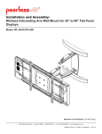
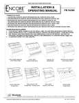
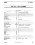
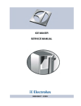
TC 9-524
Chapter 9
MILLING-GRINDING-DRILLING AND SLOTTING ATTACHMENT
(VERSA-M IL)
GENERAL
DESCRIPTION
The milling-grinding-drilling and slotting attachment is
commonly referred to as a Versa-Mil. It is a compact,
portable unit capable of doing many machining operations
that normally require expensive single-purpose machines.
With the different attachments that are available with the
unit, drilling, shaping, milling, and grinding can be
performed quickly and inexpensively. This self-powered,
vertical-feed, variable-speed precision tool may be mounted in
any position on the carriage, table, ram, turret, or tool arm of
other machine tools. With a two-directional feed table, the
Versa-Mil unit becomes a complete machining tool for bench
or inplace machining of parts too large to be moved or held in
conventional machine tools.
USES
An important factor in the efficiency of the Versa-Mil is
that machine tools already in the shop area provide the power
for feeds, a means of holding and moving the work, and the
rigidity needed for machining. Faced with unusual machining
problems, the Versa-Mil offers many solutions either as a
separate tool or combined with other machine tools and
machinery already in the shop to create special machines. The
Versa-Mil increases the capabilities of standard machines by
doing secondary operations without changing setups. The
Versa-Mil provides power to interchangeable attachments
allowing the unit to be used on site to perform different
machining operations on equipment being repaired or rebuilt.
Where space is limited, as in a shop area, floor space is
needed only for the lathe. Different sizes of the Versa-Mil
unit are available for light, medium, and heavy machining.
This chapter will be limited to the Series 31 (light machining
unit).
Avoid dangerous environments. Do not use the VersaMil in damp or wet locations. Do not expose the VersaMil to rain.
Keep visitors away from running equipment. Keep
visitors a safe distance from the Versa-Mil while it is in
operation.
Store tools when not in use. Store or lock tools and
equipment in the Versa-Mil cabinet.
Do not force the equipment. The Versa-Mil will do the
job better and safer at the rate for which it was designed.
Wear proper apparel. Keep shirt sleeves above the elbow.
Remove ID tags, watches, rings, and any other jewelry
when working around the Versa-Mil.
Use safety glasses. Wear safety glasses when operating
any type of machine shop equipment.
Do not abuse the electrical cord. Never carry the VersaMil by the electrical cord or pull on the cord to
disconnect it from the receptacle. Keep the cord away
from excessive heat, oil, and sharp edges. Replace end
connectors or cords when excessive wear or damage is
apparent.
Maintain tools with care. Keep tools and cutters sharp
and clean for the best performance. Follow instructions
in the Versa-Mil Operation and Service Manual for
lubricating the basic unit and changing accessories.
SAFETY PRECAUTIONS
Disconnect equipment not in use. Ensure the Versa-Mil
is disconnected when not in use, before servicing, and
when changing attachments, speeds, cutters, or arbors.
Safety in the shop area or around power equipment cannot
be overemphasized. Each piece of equipment has safety
procedures unique to that particular piece of equipment.
Listed below are safety procedures that pertain to the VersaMil.
Remove chuck keys and wrenches. Form a habit of
checking to see that chuck keys and wrenches are
removed from the unit prior to operating the equipment.
Remove all tools from the area that may vibrate off the
equipment and into moving parts.
9-1
TC 9-524
Avoid accidental starting. Place protective cover around
the switch to help prevent accidental starting of the
Versa-Mil. Ensure switch is off before connecting the
unit to a power supply.
Pulley guard. The pulley guard must be in place before
operating the Versa-Mil. This prevents fingers or
clothing from getting caught between the belt and
pulleys.
Outdoor use of extension cords. When using the VersaMil outdoors, use only extension cords designed and
marked for outdoor use.
Handle cutters with care. Handle all cutters with a cloth
to prevent accidental cutting of fingers or hands.
Reversing switch. Ensure that the reversing switch is in
the correct position for proper cutter rotation. Failure to
do this could result in damage or injury by having a
cutter or arbor dislodged from the basic unit.
Grinding wheels. Use grinding wheels with the safe
speed at least as high as the no-load RPM rating of the
Versa-Mil grinding attachment.
TOOLS AND EQUIPMENT
VERSA-MIL BASIC UNIT
The Versa-Mil basic unit (Figure 9-1) has a powered
machining head which moves vertically on four hardened
ground guide posts by means of a precision-ground lead screw
calibrated to 0.001 inch. Thirteen different speeds are
available to the head through the use of different size pulleys
9-2
to accommodate all types of machining and cutter sizes
within the range of the unit. The circular T-slot on the face of
the basic unit accommodates a variety of attachments. The
graduation marks on the basic unit indicate the degree angle
an attachment is to be positioned for various machining
operations.
TC 9-524
ATTACHMENTS
External Grinding Attachment
The external grinding head (Figure 9-2) bolts to the face of
the Versa-Mil making the unit a precision external grinder.
The head adjusts to 30 degrees range of angle to either side.
A flat belt from the motor provides power to the head for
smooth operation. Different pulley diameters allow matching
spindle speeds to the grinding wheel size and rating. A wheel
guard on the head offers protection to the operator from
debris coming off the wheel during grinding.
grinding. The deep-hole grinder accommodates grinding
wheels 3 to 5 inches in diameter and grinds to a depth of 10
inches. A flat belt from the motor drives the deep-hole
grinder for smooth operation. Six spindle speeds are available
to match the spindle speed to the grinding wheel diameter
and rating.
Tooth Stop Rest
Internal Grinding Attachment
Cutters held in the lathe chuck, collet, or between lathe
centers can be ground quickly and accurately with the VersaMil unit equiped with an external or internal grinding head.
The tooth stop rest (Figure 9-5) assures uniform grinding of
cutter teeth because the finger on the gage ratchets over the
teeth stopping each tooth in the exact same position. The
tooth stop rest is completely adjustable for height and
position.
A wide variety of internal grinding jobs can be handled on a
lathe with the Versa-Mil basic unit and the internal grinding
unit (Figure 9-3). The internal grinding attachment bolts to
the face of the basic unit and is driven by a flat belt from the
motor. The internal grinder handles grinding wheels from 5/8
inch to 2 1/2 inches in diameter and grinds to a depth of 4
inches. Five different speeds are available to match the
spindle speed to the grinding wheel diameter and rating.
Heavy-Duty Deep-Hole Grinder
The heavy-duty deep-hole grinder (Figure 9-4) may be
attached to the face of the Versa-Mil for deep internal
9-3
TC 9-524
Diamond Dresser
The diamond dresser (Figure 9-6) is used with all Versa-Mil
grinding attachments and clamps to the workpiece, tailstock,
or lathe face plate to true the grinding wheel. A 0.35-karat
industrial diamond mounts in either of two positions to dress
the face or side of the grinding wheel. The cast-iron frame
with V-notch clamps securely to round shapes up to 3 1/2
inches in diameter.
0 to 4 inches with a speed of 44 to 450 strokes per minute.
Tool holders for l/8”, 3/16”, 1/4”, 5/16”, and 1/2” cutters are
available for use in the Versa-Shaper.
Universal Milling Head
The universal milling head (Figure 9-7) mounts to the face
of the Versa-Mil and is driven by the spindle of the basic unit.
This feature eliminates the need for special belts and permits
the head to operate at any angle. The milling head and the
basic unit have the same spindle taper and use the same
arbors. With the universal head, machining can be performed
along the side of the work, allowing the machining of much
larger parts. Angular operations such as thread milling can
easily be performed on large diameter material using the
universal head.
HIGH-SPEED END MILLING
For speeds higher than the basic unit can provide, a highspeed end milling and drilling head (Figure 9-9) bolts to the
face of the Versa-M il. The head rotates 30° in either direction
from center. Graduation marks on the face of the basic unit
indicate the angle setting. Thirteen spindle speeds are
available to the head directly from the motor through the use
of a V-belt and pulleys. Arbors may be mounted in either end
of the high-speed head. The spindle taper is the same as the
basic unit. The high-speed head is used mostly for small
diameter work such as end milling, drilling, or other related
operations.
Internal Keyseater and Slotter
This unit bolts to the face of the Versa-Mil and is driven by
the basic unit spindle. The An internal keyseater and slotter
(Figure 9-8) commonly called a “Versa-Shaper,” bolts to the
face of the Versa-Mil Versa-Shaper operates in any angular
position and in either direction of stroke for cutting internal
keyways, slotting, or shaping. Thestroke length adjusts from
9-4
TC 9-524
Indexing Head
Adapter Base Mounting
The indexing head (Figure 9-10) mounts in the lathe head
stock spindle to index work held in the lathe chuck, collet, or
between lathe centers. The indexing head mandrel locks into a
1 1/8-inch or larger spindle bore; however, adapters for other
bores are available. Forty turns of the dividing head crank
rotates the lathe spindle one revolution. The indexing plate has
18 circles of holes allowing for divisions to be made in
degrees, number of sides, or the number of teeth on gears or
splines.
When a lower mounting of the Versa-Mil unit is required,
the compound rest can be removed and replaced with a special
adapter base (Figure 9- 12) that mounts directly on the crossslide. The base plates are semifinished and may require
drilling two mounting bolt holes and a pivot pin hole. The
location of these holes depends upon the lathe model and size.
The base plate adapter should be used for operations on or
below the centerline of the workpiece. Such operations
include milling keyways along the side of a shaft, surface
milling with a shell end mill, and drilling or boring on the
centerline of the workpiece. The compound rest must be
removed prior to mounting the base plate adapter.
T-Slot Mounting Adapter
Versa-Mil units are furnished with an adapter (Figure 9-11)
that fits the T-slot of the compound rest on most conventional
lathes to lock the Versa-Mil unit to the compound rest with
two hex-head bolts. Four holes in the base of the Versa-Mil
unit allow mounting the basic unit in any of four positions 90°
apart. Mounting the basic unit by this method permits the use
of the compound rest for angular movement where low
mounting of the Versa-Mil is not required. Any operation
normally done above the centerline of the workpiece is
usually accomplished by using the T-slot adapter and the compound rest. Such operations include milling keyways, slots,
and splines, angle milling, and gear cutting. Other operations
such as drilling or boring may also be accomplished if they
are performed above the center line of the work.
FEED TABLES
Although not part of the basic unit accessories, the feed
table may be found in some shop sets. Rigid accurate feed
tables (Figure 9-13) make the Versa-Mil unit a portable
machine tool by providing two additional directions of. travel.
Precision finished ways, adjustable gibs. and accurate lead
screws calibrated to 0.001 inch assure accurate positioning
and feed for the most precise machining. Feed tables for
Versa-Mil units are available in four different models and all
feed tables can be quickly converted to reduce table height
when only one direction of travel is required.
9-5
TC 9-524
Machining done on the lathe with a Versa-Mil allows the
cutter to move along three different axes: vertical, lateral, and
longitudinal (x, y, z). However, not all machining can be done
using the lathe. Because the lathe allows longitudinal and
lateral movement, mounting the Versa-Mil directly to a bench
or piece of equipment would severely restrict its machining
capabilities. Feed tables eliminate that restriction by providing
those two additional directions of travel. Feed tables mounted
directly to a bench or piece of equipment allow the Versa-Mil
to perform machining in all three directions.
SELECTION OF ARBORS
When the basic unit is to be used independently or with an
attachment other than the grinding attachments, an arbor and
cutter must be selected and mounted. The cutter should be
mounted onto the arbor first. The arbor should be secured in a
vise to properly mount the cutter.
This ensures a properly torqued cutter and prevents the arbor
from bending or causing damage to the Versa-Mil basic unit.
When tightening the arbor nut, the pressure applied to the
wrench should always be in the direction of the operator in
case of slippage. Listed in the following paragraphs are
various arbor styles and some of their uses. Note that they are
similar to, but smaller than those used on a milling machine.
Refer to chapter 8 for illustrations not listed.
Shell End Mill Arbor
The shell end milling arbor is used primarily for facing;
however, milling a wide slot with a shell end mill can be
accomplished.
Geared Chuck Arbor
This type of arbor is used for mounting chucks with a #3
Jacobs taper. The chuck itself is used primarily for drilling.
Straight Shank Arbor
The straight shank arbor with setscrews is used with straight
shank drills of the correct size, end mills, and Woodruff key
seat cutters.
Taper Arbors
Taper arbors (Figure 9-14) are designed primarily for use
with Brown and Sharpe, or Morse standard taper shank tools.
Straddle Mill Arbor
The straddle mill arbor is used for milling splines on a shaft,
milling hexagon or square shapes, and large keyways. Six
spacers come with the Versa-Mil accessories, allowing milling
of areas from 1/8 to 3 inches wide in 1/16 inch increments.
Fly-Cutting Arbor
The fly-cutting arbor may be used for boring, facing, gear
repair, keyway milling, and form milling. This type of arbor
allows the tool bit to be positioned at either 45° or 90° to the
arbor axis.
Side-Milling Arbor
The side-milling arbor (Figure 9-15) is used with arbor-type
cutters and slitting saws. This arbor is supplied with 1/8” and
3/8” spacing collars.
9-6
Threaded Angle Mill Arbor
The threaded angle mill arbor is used for milling angular
grooves and dovetails.
SELECTION OF CUTTERS
After selecting the arbor, select the desired cutter for the
machining process, mount the cutter on or in the arbor, and
mount the arbor in the Versa-Mil unit or attachment. Ensure
the arbor and spindle are free of dirt and burrs.
TC 9-524
Woodruff Key Slot Cutters
This cutter has a l/2-inch straight shank and is used for
cutting Woodruff keyslots in a shaft. This cutter may also be
used for cutting straight keyways in a shaft or similar
operations.
Side Cutters
Side cutters are available in two basic styles. The stagger
tooth side milling cutter should be selected for milling
keyways and deeply milled slots, while the straight side
milling cutters are usually used in matched sets for straddle
milling or individually for side milling.
Shell End Mill Cutter
This cutter is used for slabbing or surfacing cuts and end or
face milling.
SELECTION OF GRINDING WHEELS
When the external grinding head, internal grinding head, or
deep-hole grinding head is selected and mounted on the
Versa-Mil, a wide range of grinding operations is made
available. The data books published by the leading abrasive
manufactures should be referred to for proper selection of
grinding wheels as the variety of grinding done by Versa-Mil
is to great for complete coverage of wheels in this manual.
WARNING
Use only abrasive wheels designed for the external or
internal grinding heads that have been tested and found to be
safe when operating at the speeds attained by these heads.
Using incorrect untested wheels may result in breaking the
abrasive wheel causing wheel fragments to be projected into
the work area endangering personnel and equipment.
Form Cutters
Straight Abrasive Wheels
Form cutters are manufactured in a variety of shapes.
Selection of the cutter depends upon the desired shape or form
to be machined.
Straight abrasive wheels are furnished in 46 and 60 grit
sizes. The 46 grit wheel is a general-purpose wheel and should
be selected for rough-grinding cylindrical parts, face plate
grinding, and so forth. Select the 60 grit wheel for finishing
and for tool and cutter grinding where finer finishes are
required.
Fly Cutters
Fly cutters are usually square tool bits ground with the
proper clearances for boring, facing, or counterboring. Fly
cutters can also be ground to particular shapes for special jobs
such as gear repair or spline milling.
END MILLS
Straight Cup Wheels
Select a straight cup wheel should be selected for tool and
cutter grinding, face plate grinding, and internal grinding of
large holes.
Flare Cup Wheels
End mills are manufactured in a variety of shapes and styles
and should be selected in accordance with the job to be
performed. The two fluted end mills are recommended for
cutting keyways and for deep milling while the multiple flute
end mills are designed for end milling and routing work.
Select a flare cup wheel for general tool and cutter grinding.
SLITTING SAWS
Select a dish wheel for tool and cutter grinding such as
grinding flutes and individual teeth of milling cutters.
Dish Wheels
Slitting saws are manufactured in a variety of styles and
sizes and should be selected in accordance with the job to be
performed. Use slitting saws to cut deep slots in the work and
for cutting slots.
9-7
TC 9-524
VERSA-MIL OPERATIONS
SETUP
The Versa-Mil adds important machining functions to a
lathe. With built-in power and vertical feed, it adds a third
machining dimension, allowing the operator to mill, drill,
bore, slot, shape, grind, and perform other special operations.
The success of any Versa-Mil operation depends largely upon
the judgment of the operator in setting up the Versa-Mil,
selecting the proper cutter, and holding the cutter by the best
means possible under the circumstances.
Preoperational Checks
Gibs should be as snug as possible and still allow the
movement needed. Tighten all gibs not required for the
operation being done to prevent movement and chatter. The
adjusting bar on the back of the lathe carriage that holds the
carriage onto the lathe bed should be snug enough to still
allow a slight drag when feeding the lathe carriage. If the
work is held between centers, they should be tight against the
work and long pieces should be supported at the point where
machining is being done. Unless both the Versa-Mil and the
work are rigidly supported, it is difficult to obtain accurate
results.
Mounting on a Lathe
The Versa-Mil may be mounted on the front or the rear of
the lathe carriage. On the front, it may be set on the compound
rest or directly on the cross slide. A more permanent and
generally more useful mounting is at the rear of the lathe
carriage, where it may be left until it is needed.
Squaring the Versa-Mil to the Lathe
For accurate milling cuts, it is necessary to square the VersaMil to the lathe (Figure 9-17). The front compound face of the
Versa-Mil is a reference surface machined in relation to the
spindle. A square can be set across this face and squared to
the chuck or face plate of the lathe. For work between centers,
the Versa-Mil can be squared to the workpiece. After the
machine has been squared on the compound rest of the lathe,
the compound rest can be loosened for adjusting the spindle to
various angles using the graduated scale on the compound
rest. For extremely precise adjustments and settings, use the
dial indicator or vernier protractor.
9-8
MILLING SQUARE END KEYWAYS
Conventional milling is recolmmended when using the
Versa-Mil on a lathe as the lathe’s feeds and bearings are not
designed for upward pressure on the carriage. Cutting square
end keyways (Figure 9-18) can be accomplished with the
Versa-Mil using a variety of different cutters and speeds. The
Versa-Mil is usually set on top of the compound rest with the
spindle of the Versa-Mil parallel with the travel of the
compound rest. Select and mount the cutter to the appropriate
arbor. A stagger tooth side milling cutter the width of the
keyway is the most satisfactory cutter to use for square end
keyway milling operations; however, plain milling cutters
may be used. Mount the arbor into the Versa-Mil spindle and
tighten.
CAUTION Do not over tighten as the pin in the back of
the Versa Mil may shear
TC 9-524
Speed Selection
Feed Rate
If a good flow of coolant is available to the cutter, choose or
select speeds near the top of the recommended cutting speeds
for the operation being performed, type of cutter used, and
material being milled. If milling is to be done dry, then use a
speed at the lower end of the recommended cutting speeds.
The rate of feed will vary from 0.001-inch chip thickness
per tooth to as much as 0.008 inch per tooth. Determine the
feed rate by multiplying the number of teeth on the cutter
times the desired chip thickness times the RPM of the cutter.
A chip thickness of 0.001 to 0.004 is considered a finishing
cut while a chip thickness heavier than 0.004 is considered a
roughing cut. Most milling operations involving the Versa-Mil
are fed by hand. The operator should attempt to feed the cutter
at a consistent rate with each tooth taking the same chip
thickness. Power feeding is recommended when long cuts
along a shaft or workpiece are necessary. To do this, mount
the steady rest on the lathe close to the headstock and clamp
the steady rest tightly against the workpiece. Lubricate the
headstock center or use a ball bearing type center to allow the
headstock spindle to rotate freely while the workpiece remains
stationary. If a ball bearing center is not used, maintain low
spindle speeds to prevent overheating the work. Feed rates
during power feeding are adjusted using of the quick change
gearbox on the lead screw.
Centering the Cutter
To center the cutter over the work, tirst ensure the backlash
is removed from the cross slide. Next, start the Versa-Mil and
reference the cutter to the side of the work using a paper shim.
Zero the cross feed dial; then, raise the Versa--Mil above the
top of the work. To determine the distance the cutter must
move, add one-half of the diameter of the cutter plus one-half
the diameter of the workpiece plus the thickness of the paper
shim. Keep in mind some latches only move half the distance
shown on the crossfeed dial. After the cutter has been moved
over the center of the work lock the cross slide to prevent
movement during milling. See Figure 9-19.
INTERNAL KEYWAY AND SPLINE
CUTTING
After the internal diameter of gears or sleeves have been
machined to size, keyways or splines may be cut into the work
with the Versa-Shaper without removing the work from the
lathe chuck (Figure 9-20). This has a major advantage of
saving time by not having to change setups.
Depth of Cut
Start the Versa-Mil and reference the cutter to the top of
the workpiece using a paper shim. The depth of cut equals
one-half the key thickness plus the chordal height plus the
thickness of the paper shim. Tables for chordal height may
be found in the new American Machinist’s Handbook or
Machinery’s Handbook. A simple approximate formula for
chordal height is key thickness squared, divided by four
times the shaft diameter. After the depth of cut is
determined and set, tighten the post binding setscrew to
prevent the basic unit from moving during machining.
Sizes of Keyways
Each of the standard widths of keyways from 1/8 to 1/2 inch
may be cut with one of the standard keyway cutters available
with the Versa-Mil. Wider keyways may be cut with one of
the standard cutters by cutting the slot to the proper depth and
enlarging it by feeding the cutter first to one side and then the
other through the use of the cross slide lead screw.
9-9
TC 9-524
Depth of Cut
Depth of Cuts
Determine the depth of cut by the amount of feed applied to
the basic unit lead screw. However, it is necessary to allow the
Versa-Shaper to take additional cuts (free cuts) until no further
material is removed before taking a measurement. This will
assure accurate keyways or splines being machined in the gear
or sleeve.
In the case of shell end mills, the depth of cut should not
exceed the depth of the teeth or flutes. With side milling
cutters, the depth of cut is controlled by the diameter of the
cutter. For deep cuts, a staggered tooth, side milling cutter is
recommended. Extremely light cuts should be avoided if
possible as the cutter tends to slide over the work, heating and
dulling the cutter which may result in putting undo pressure
on the arbor and carriage causing excessive chatter.
Direction of Feed
Whenever practical, mill keyways and splines by feeding
upward with the Versa-Shaper. This will cause the lathe
carriage to be held more firmly in contact with the lathe ways
and the lathe bed, permitting heavier cuts to be taken.
Clearance
After the Versa-Shaper is set up, run through the entire
stroke cycle turning the worm sheave by hand. This will
ensure that the cutter clears the work at both ends and does not
strike the lathe chuck or encounter any other obstructions.
PLAIN MILLING
Plain milling or slabbing (Figure 9-21) is a term applied to
many operations such as face milling, milling a hex or square
shape, or milling flat surfaces along the side of a workpiece.
The process of plain milling normally involves removing large
amounts of material with either a shell end mill or side milling
cutters to form a flat surface. Work may be held either in the
lathe chuck or between centers for plain milling.
Milling Feeds
The best milling performance is obtained when each tooth
of the cutter takes a full chip. When milling steel, for
example, the ideal feed is 0.005 inch. Depending on the
width of the cutter and machinability of the material, it
may be desirable to reduce the depth of cut and increase the
rate of feed to maintain chip thickness. Chatter is likely to
result when chips are too thin, causing cutter life between
grindings to be reduced.
DRILLING
Many drilling and boring operations not ordinarily possible
on the lathe are easily performed with the Versa-Mil mounted
on the lathe. The Versa-Mil is usually fed by hand using either
the either carriage, cross slide, or compound rest. Check the
operators manual supplied with the Versa-Mil for information
concerning power feeding when drilling.
Off-Center Drilling
Off-center drilling and boring may be performed by
positioning the Versa-Mil spindle parallel with the lathe axis
and maneuvering the drill by means of the cross slide and the
Versa-Mil lead screw. This allows the complete machining of
irregularly-shaped items without removing them from the
lathe chuck. See Figure 9-22.
9-10
TC 9-524
Angular Drilling
With the Versa-Mil mounted on the compound rest, holes
may be drilled at any angle in relation to the lathe axis by
setting the compound rest at the desired angle and feeding the
drill into the work with the compound rest lead screw. To use
power feeding with the taper attachment, set the taper
attachment and Versa-Mil spindle parallel with the hole to be
drilled. The work must be held in position to prevent turning
when the lathe carriage feed and head stock spindle are
engaged. See Figure 9-23.
Additional Drilling Applications
Drilling with the Versa-Mil attached to a feed table, turret
lathe, or vertical boring mill is unique. Special drilling
operations with these pieces of equipment are covered in the
operator’s manual on the Versa-Mil. See Figure 9-24.
WOODRUFF KEYSLOT MILLING
Index Drilling
Stock held in the lathe chuck or between centers can be
drilled at regular intervals around the center or perimeter of a
workpiece by using the indexing head to position the work. A
considerable amount of setup time and effort is saved after
positioning the drill for the first hole to be drilled.
Milling Woodruff keyslots (Figure 9-25) in shafts is very
similar to milling straight keyways in the basic setup,
centering the cutter, and feed rate. The only difference in
milling a Woodruff keyslot is that the carriage must be locked
down in addition to the cross slide, if cutting from the top of
the workpiece, to prevent the basic unit from moving during
milling. Cutting a Woodruff keyslot is relatively simple since
the proper size cutter has the same diameter and width of the
key to be inserted. The work may be held in the lathe chuck or
between centers and the cutter may be on an arbor or in a drill
chuck. After the cutter has been centered on the work, the
cutter is fed directly into the work until the proper depth of cut
has been achieved.
9-11
TC 9-524
FORM MILLING
Form milling is the process of machining special contours,
composed of curves and straight lines or entirely of curves, in
a single cut. Gear cutting may be considered form milling by
definition; however, the definition iS usually restricted to the
use of convex, concave, or corner rounding cutters. These
form cutters are manufactured in a variety of radii and sizes
and may be grouped or ganged together on an arbor to mill
intricate shapes. Convex (curved or rounded outward) cutters
mill concave (curved or rounded inward) shapes while
concave cutters are used to mill convex shapes.
ANGLE MILLING
Angle milling is milling flat surfaces which are neither
parallel nor perpendicular to the work. Angular milling can be
divided into several different types of setups.
INDEXING
Single Angle Milling Cutters
An indexing head comes with the Versa-Mil and is installed
on the headstock of the lathe to permit indexing a workpiece.
Even though the workpiece is mounted in a conventional
manner in the lathe, the headstock spindle should never be
allowed to rotate under power with the indexing head attached
as this would cause severe damage to the equipment. It is
always a good practice to unplug or turn off the main power
switch on the lathe in this situation.
Single angle milling cutters are mounted on an arbor and the
arbor is then mounted to the basic unit or universal head. The
unit is then squared to the workpiece and the work is milled in
a conventional manner. This type of cutter is manufactured in
a variety of angles with the most common angles being 45°,
50°, 55°, or 60°.
Mounting the Workpiece
When cutting dovetails with the Versa-Mil, the workpiece is
usually held in the lathe chuck or mounted on a face plate.
The tongue or groove of the dovetail is first roughed out using
a side milling cutter, after which the angular sides and base
are finished with the dovetail cutter. See Figure 9-26.
A workpiece may be supported in the lathe between centers,
against the faceplate, or in the lathe chuck. If the work is
mounted between centers, a lathe dog is mounted on the work
and used to transfer movement from the faceplate to the work.
Indexing the Work
Indexing is the process of controlling the rotational position
of a workpiece during machining. The indexing head attaches
to the left end of the lathe headstock and locks into the
headstock spindle using an expansion adapter. With the
indexing head mounted to the lathe, the work will not rotate
unless the crank arm of the indexing head is moved. Forty
complete turns of the crank arm move the lathe spindle one
revolution. The indexing plate contains a series of concentric
rings with each ring containing a different number of holes.
The workpiece is indexed by moving the crank arm from one
hole to another through a calculated pattern of turns and holes.
To determine the correct pattern of turns and holes and which
ring to use, refer to Chapter 8, Indexing a Workpiece.
9-12
Dovetail Milling
TC 9-524
Compound Rest
Tailstock Offset
Angular milling may also be accomplished on the Versa-Mil
by squaring the Versa-Mil on the compound rest and setting
the compound rest to the desired angle. With this method of
angular milling, the cutter is usually a shell end mill and the
work is either held in the lathe chuck or mounted on the
faceplate.
This type of angular milling is accomplished by squaring the
unit to the tailstock spindle or faceplate. Normally, a shell end
mill is used in this type of milling. Work is mounted between
centers and the tailstock is offset to the desired angle for
milling. The work may be rotated with the indexing head to
mill additional surfaces on the workpiece. See Figure 9-29.
Universal Head
Angles may also be milled on a workpiece using the
universal head. This head may be tilted to 180° in either
direction of center. Complex angles may be machined with the
universal head used in conjunction with the compound rest or
the tailstock offset method. See Figure 9-28.
STRADDLE MILLING
Straddle milling (Figure 9-30) is the machining of two
parallel surfaces in a single cut by using two cutters separated
by spacers, washers, or shims. Use straddle milling in spline
milling or the cutting of squares or hexagons on the end of a
cylindrical workpiece. The workpiece is mounted between
centers to mill splines on a shaft and mounted in the lathe
chuck to mill squares or hexagons. In both cases, the indexing
head is used to rotate the work after each cut.
9-13
TC 9-524
each spline to the proper depth and indexing around the shaft
for each spline. A narrow plain milling cutter is used to mill
the spaces between the splines to the proper depth. It may be
necessary to make several passes to mill the groove uniformly
around the shaft. A formed cutting tool or cutter may also be
used for this operation.
SPLINE MILLING (INTERNAL)
After a hub or gear has been drilled and bored to the
finished internal minor diameter, internal splines may be cut
into the hub or gear by using the Versa-Shaper (Figure 9-31).
The indexing head provides the means to locate each spline to
be cut. For this operation, the milling is continued until the
desired class of fit is obtained. For field expedience, it is best
to machine the mating parts to match if possible.
GANG MILLING
Gang milling differs from straddle milling in that two or
more cutters of different diameters or shapes are mounted on
the same arbor to mill horizontal surfaces. Cutter
combinations in gang milling are virtually unlimited and are
determined by the desired shape of the finished product.
SPLINE MILLING (EXTERNAL)
SLOTTING
Splines are often used instead of keys and keyways to
transmit power from the shaft to a hub or gear. Splines are a
series of parallel keys and keyways evenly spaced around a
shaft or interior of a hub. Splines allow the hub to slide on the
shaft either under load or freely. This feature is found in
transmissions, automotive mechanisms, and machine tool
drives. Manufactured splines are generally cut by bobbing and
broaching; however, this discussion will be limited to field
expedient methods. Standard splines on shafts and spline
fittings are cut with 4, 6, 10, or 16 splines.
Slotting with the Versa-Mil (Figure 9-32) covers a wide
variety of operations from milling long wide slots in material
to cutting curved or thin slots. Workpieces may be mounted in
the lathe chuck or between centers for slotting operation.
The dimensions depend upon the class of fit and the shaft
diameter. The class of fit may be permanent, sliding fit not
under load, and sliding fit under load. Table 8-8 in Appendix
A lists the standard dimensions for the different classes of fits.
Shafts may be milled several different ways.
The most common way is to use two side milling cutters
separated by spacers, with the width of the spacers equal to
the width of the spline. The splines are cut by straddle milling
9-14
TC 9-524
Longitudinal Slots
Plain or Face Milling of Soft Nonferrous Metals
Longitudinal slots along a shaft or other large piece may be
cut in the material in the same manner as milling keyways
with end mills. It is often desirable to use a cutter smaller than
the width of the slot. The reason for this is, when the cutter is
as wide as the slot, one side of the cutter is climb milling
while the opposite side of the milling cutter is performing
conventional milling. This causes a difference in the finish
between the two sides of the slot. A roughing out of the slot
should be made first, followed by a finishing cut down one
side of the slot and returning on the other side.
Plain or face milling of soft nonferrous” metals such as
aluminum, with a fly cutter produces a high quality finish.
Boring holes with a fly cutter is generally not desirable
because of the difficulty in positioning the cutter and
controlling the diameter. The short arbor allows boring of only
very shallow holes.
Narrow Slots
For narrow slots, use slitting saws rather than end milling
cutters. When using slitting saws, reduce speeds and feeds to
extend the life of the cutter.
FLY CUTTING
Fly cutting (Figure 9-33), also called single-point milling, is
one of the most versatile milling operations available to the
machinist. Fly cutting is done with a single-point cutting tool,
like the lathe or shaper cutting tool, held in a fly cutting arbor.
Formed cutters are not always available and there are times
when special form cutters are needed only for a very limited
number of parts or operations; therefore, it is moreeconomical
to grind the desired form on a lathe cutter bit rather than order
a special form cutter. The fly cutter is used to great extent in
the reshaping of repaired gears because the tool bit can be
ground to the shape of gear teeth available. Fly cutting can
also be used in cutting standard and special forms of splines.
Gear Cutting
A variety of gears, pinions, and sprockets can be fabricated
on the lathe using the Versa-M il. By referring to various texts
and references for detailed data and instructions on gears and
gear cutting, the operator can develop different methods of
mounting the Versa-Mil to the lathe to perform gear cutting.
The basic unit and the indexing head are the two basic
elements needed to cut gears. When large diameter gears need
to be cut, the universal head is used to mill the side of the
gear.
Spur gears are the most common type of gear used in the
field and the correct cutter to use for this type of gear is
determined by the pitch of the teeth and the number of teeth
required. Standard cutter catalogs supply the data necessary to
select the correct cutter.
Gear Cutting with the Basic Unit and an
Involute Gear Cutter
In this setup, Figure 9-34, the gear blank is first turned to the
correct diameter using a mandrel mounted between centers.
The blank should remain on the mandrel after turning. The
lathe dog should be wedged against the faceplate to eliminate
backlash and the indexing head mounted to the lathe spindle
to position the individual teeth. The basic unit is mounted on
the compound rest with the faceplate parallel to the lathe
center and an arbor with an involute gear cutter, stamped with
the correct pitch and number of teeth, is installed in the basic
unit. After the cutter is positioned, lock down the cross feed
by tightening the gibs. When the correct depth is reached,
tighten the post locking screw on the basic unit. The cutter is
then fed into the blank by hand using the lathe carriage wheel.
9-15
TC 9-524
Gear Cutting with the Basic Unit
and a Fly Cutter
When an involute gear cutter is not available or delay in
obtaining one is too great, a fly cutter is used. The only
difference is that a fly cutter with a 5/16-inch square tool bit,
ground to the correct shape, is used instead of an involute gear
cutter. See Figure 9-35.
Gear Cutting with a Universal Head
Used this setup with either a fly cutter or an involute gear
cutter on gear blanks larger than 8 inches in diameter. See
Figure 9-36.
9-16
WHEEL DRESSING
Wheel dressing (Figure 9-37) with the diamond dresser is a
must for accurate precision grinding. Dress wheels before
starting any grinding job and again prior to the finishing cut.
The diamond dresser is the most efficient type of wheel
dresser for truing wheels used in precision grinding. The
diamond point is the only usable part of the diamond and must
be inspected frequently for wear. Rotate the diamond slightly
in the holder between dressings to keep the point sharp. A dull
diamond will press the wheel cuttings into the bonded ores of
the wheel, increasing the wheel’s hardness. When truing the
wheel, the diamond should be centered on the wheel and
slanted between 5° and 15° in the direction of wheel rotation
to prevent chatter and gouging.
TC 9-524
The grinding wheel should rotate at or slightly less than
operating speed when truing or dressing, never at a higher
speed After truing, slightly round the edges of the wheel with
an oilstone to prevent the wheel from chipping, unless the
work requires sharp comers. Start the dressing process at the
highest spot on the wheel, normally the center, and feed at a
uniform rate with a 0.002 inch depth of cut per pass. Too slow
a feed will glaze the wheel while too fast a feed rate will leave
dresser marks on the wheel.
GRINDING
A wide range of grinding is made available to the machinist
by using the Versa-Mil and the different grinding heads
supplied with the unit. Refer to references published by the
leading abrasive manufacturers when selecting the proper
wheel for the job being performed. For maximum metal
removal and minimum wheel wear, surface speeds of the
grinding wheel should be near the highest allowable speed for
the wheel size. Light cuts at full speed will remove metal
faster than deep cuts at slow speeds. In general, rough cuts
average 0.002 inch per pass, while finishing cuts average
0.0005 inch. The spindle rotation should be selected to throw
wheel and metal debris away from the operator. When
movement of the work is required during grinding, the work
and the wheel should rotate in the same direction. This allows
the wheel and work to move in opposite directions at the point
of contact. The precision grinding may be done either wet or
dry.
CYLINDRICAL GRINDING
The lengths and diameters of shafts ground on a lathe are
determined by the lathe swing and the distance between the
lathe centers. Mount the Versa-Mil on the compound rest with
the face of the basic unit parallel to the work surface. In
cylindrical grinding (Figure 9-39), the work rotates slowly
while the wheel rotates close to the highest allowable speed.
The wheel should never leave the work at either end of the cut
in order to produce a smooth surface free of wheel marks.
Direct the spark pattern downward onto a dampened cloth to
prevent very small particles of material from getting into and
destroying machined surfaces. A spark pattern directed
downward and away from the operator indicates the wheel is
too low on the work, while a spark pattern that is directed
downward and toward the operator indicates the wheel is too
high on the work. Conical grinding can be accomplished with
either the taper attachment or by the tailstock offset method.
GRINDING LATHE CENTERS
Before grinding work between centers takes place the
centers should be ground true (Figure 9-38). With the center
mounted in the lathe headstock, mount the Versa-Mil on the
compound rest and set the compound rest at one-half the
included angle of the center. Grind the center by feeding- the
compound lead screw by hand at a uniform rate of feed.
INTERNAL GRINDING
Holes and bores as deep as 18 inches may be internally
ground using the Versa-Mil. The diameter of the hole may be
any size larger than 3/4 inch. Either the internal grinder with
the taper spindle or the deep-hole grinder may be used,
depending on the hole dimensions. Internal grinding differs
from external grinding basically in one area. The surface
contact between the work and the wheel is much greater in
internal grinding, causing the wheel to load and glaze much
more quickly. This loading or glazing will cause unnecessary
vibration and produce a poor surface finish. A coarser wheel
grain structure, which provides better chip clearance, or a
softer wheel that will break down more easily, should be used
for internal grinding. While grinding, the wheel should clear
the end of the work at least one half the wheel thickness but
not more than two thirds. If the wheel is allowed to clear the
end of the work entirely, a bell-shaped effect will be
produced.
9-17
TC 9-524
Tapered Spindle Grinder
For shallow and small diameter holes up to 6 inches in
depth, use the tapered spindle internal grinder. Tapers may
also be ground on the work by using either the taper
attachment or the compound rest. See Figure 9-40.
Versa Grinder Head
The Versa-Mil external grinder with the wheel guard
removed may be used for internal grinding of large bored
pieces if a considerable amount of stock must be removed and
the hole depth does not exceed the unit clearance. This setup
permits the operator to grind internally, externally, and face
in one setup, assuring a true relation between the three
different surfaces. See Figure 9-42.
Deep Hole Grinder
The deep-hole grinder with the extended housing offers a
rigid precision grinder for holes as deep as 18 inches. Tapers
may also be ground with the deep-hole grinder. See Figure 941.
SPECIAL OPERATIONS
TOOL GRINDING
The Versa-Mil mounted on the compound rest of a lathe
will duplicate the full range of tool and cutter grinding
offered by conventional tool grinders. For successful results,
the lathe should be in excellent operating condition and
preferably small in size to permit the close setting of feeds
and angles. Versa-Mil spindles use precision, spring-loaded
duplex bearings to eliminate play in the grinding wheel
forsuccessful tool grinding. The Versa-Mil tool rest is solidly
constructed to provide rigid support with a tip that is designed
for smooth, solid contact under the teeth or flutes of the tool
being ground. The operator familiar with tool grinding and
9-18
the use of the Versa-Mil soon develops methods for grinding
the various types and forms of cutters. Tool grinding cannot
be completely covered in this manual, and it is suggested that
reference material covering tool grinding be consulted for
complete detailed instructions.
Selection of Grinding Wheels
Grinding wheels should be in the medium grit range for
tool and cutter grinding. The shape of the cutting tool will
determine which wheel design to use. Abrasive
manufacturers’ catalogs should be referred to for proper wheel
selection.
TC 9-524
Depth of Cut
Light traversed cuts should be used to avoid overheating and
burning the cutting edge of the tool. Dry grinding is
recommended for sharpening high speed steel because coolant
removes heat from the cutting edge too quickly causing
cracking.
Direction of Wheel Rotation
It is generally safer to have the wheel rotate off and away
from the tool cutting edge. This allows the tooth rest to
position the tooth and prevent the cutter from turning. This
method, however, has some drawbacks, in that the heat from
grinding is directed toward the tool cutting edge and leaves a
burr which must be removed with an oilstone.
TOOL SHARPENING
The efficiency of a cutter is determined by the sharpness of
its cutting edge. Therefore, it is important to sharpen a cutter
at the first sign of dullness. A dull cutter not only produces a
poorly finished surface, but if used continuously, the cutter
will need excessive sharpening to restore it to its original
efficiency.
Up Method
In this method, the wheel rotation is from the cutting edge
towards the body of the tooth. With this method, there ‘is less
danger of burning the tooth. However, the operator must
ensure that the cutter is held firmly against the tool rest. If the
cutter turns during grinding, the cutter will be ruined.
Grinding Cutters Cylindrically
Certain types of cutting tools, such as reamers and plain
milling cutters, are ground cylindrically to remove warpage
from heat treating, to remove nicks, to obtain a specific
diameter, or to produce a cutting edge with a slight clearance.
When grinding tools or cutters, the work rotates in the
opposite direction from that used in conventional grinding.
This allows movement in the same direction at the point of
contact. Mount the cutter so that the heel of the tooth makes
contact with the grinding wheel first, allowing the heel of the
tooth to be ground slightly lower than the cutting edge. This
clearance will vary slightly depending on the rigidity of the
tool being ground and the job setup. The tool to be ground can
be held in one of three ways: between centers, on a mandrel,
or on a short arbor mounted in the lathe headstock spindle.
There are actually two methods of sharpening the cutting
edges of individual teeth or flutes found on cutters.
Down Method
In this method, the rotation of the wheel is from the body of
the tooth off and away from the cutting edge. The direction of
wheel rotation holds the cutter on the tooth but will raise a
burr on the cutting edge, which must be removed by stoning.
This method has a tendency to draw temper from the metal.
See Figure 9-43.
Cutting Tool Clearance
Correct clearance on the cutting edge of any tool is essential
for heat distribution, resistance to wear, and cutting efficiency.
Not enough clearance will cause the teeth on the cutter to
drag, producing heat caused by friction, and slow cutting. Too
much clearance produces chatter and dulls the teeth rapidly.
Primary clearance angles are determined by the type of
material the cutter wil1 be used on. Secondary clearance
angles are usually 3° to 5° more than primary clearance
angles. This produces a strong tooth that provides easy control
over the width of the cutting land. The width of the land
depends on the diameter of the cutter and varies between 1/64
inch to 1/16 inch. When the width of the land becomes too
wide after several sharpening, the secondary clearance angle
must be ground to restore the land to its original width.
9-19
TC 9-524
Clearance angles are produced by positioning the wheel,
cutter, and tooth rest in different locations. When using the
Versa-Mil, it is easier to reposition the wheel by raising or
lowering the basic unit. To determine the distance in
thousands of an inch, multiply the desired clearance angle by
the diameter of the cutter times the constant 0.0088. The
constant 0.0088 is the decimal equivalent of the distance
moved 10 on the circumference of a l-inch-diameter circle.
Acme and special form threads are cut with cutters designed
for the pitch diameter required. The Versa-Mil will cut
internal, external, right-handed, or left-handed threads. Square
threads can be cut with an end mill mounted in either the basic
or the milling and drilling head.
EXAMPLE: Using the following formula clearance angle x
cutter diameter x 0.0088, a clearance angle of 7° on a 1 l/2inch-diameter cutter would be 7 x 1.5 x 0.0088, or a
movement of 0.0924 of an inch.
Grinding Form Cutters
Formed or eccentricity relieved cutters (such as gear cutters)
and concave and convex cutters cannot be sharpened in the
same manner as profile cutters. Form cutters have a definite
shape that must be retained, even after several sharpening. To
retain this shape, only the face of the cutter is ground.
Increasing or decreasing the rake on these cutters alters the
final shape of the cutter, so care must be taken to ensure that
the rake remains at the original angle. The indexing head may
be used to assure even spacing of the teeth faces.
Lathe Preparation
Thread milling speeds and feeds are approximately the same
as those used for keyway millillg and slotting. The lathe
spindle speeds needed for thread milling are generally lower
than those available on standard lathes. It is usually necessary
to use a reduction unit mounted to the lathe to obtain the
required lathe spindle speed. Large diameter workplaces may
require speeds as low as 1/2 or 1/3 RPM. Other than lathe
spindle reduction, no other modification of the lathe is needed
for thread milling. The quick change gearbox and lead screw
are set the same as for single point threading. The indexing
head may be mounted to the lathe and used to rotate the lathe
spindle when a reduction unit is not available.
Mounting the Versa-Mil
THREAD MILLING
The Versa-Mil with the universal head will enable a lathe to
mill threads to full depth and complete profile in a single pass
(Figure 9-46). Milling threads saves time and reduces the
chance for error over single pointing. USS threads may be cut
with standard 60° included angle cutters.
9-20
Even though the cutter is at or below the centerline of the
work when the basic unit is mounted on the compound rest, it
is advisable to mount the unit directly to the cross slide for
rigidity.
Supporting the Work
Work of sufficient diameter and rigidity may be supported
easily between centers. For long or small diameter work, a
steady rest or follower should be used to prevent the work
from bending away from the cutter thereby reducing the depth
of cut.
TC 9-524
Depth of Cut
For external threads, the cutter is fed into the work with the
cross feed lead screw. For internal threads, the cutter is fed
into the work with the basic unit lead screw. Because thread
milling with the Versa-Mil is a one-pass operation, total depth
of cut is calculated and set before cutting the thread.
Cutter Rotation
Consideration should be taken when mounting the cutter and
selecting the spindle rotation. Conventional milling should be
used to put pressure downward onto the carriage. A key may
have to be inserted in the arbor to prevent the cutter from
loosening the spindle nut.
Accessibility to Work
Because the universal head spindle may be operated in
either direction and mounted on either side of the basic unit,
threads may be milled at either end of the work and very close
to shoulders and flanges.
Helix Angles
The graduations on the basic unit faceplate and the
mounting plate of the universal head are used to set the
approximate helix angle. Refer to the Versa-Mil operator’s
manual for helix angles of different threads.
Thread Milling Cutters
Cutters as small as 2 3/4-inches in diameter may be used
with the universal head for external thread milling. The cutter
diameter for internal threads is governed by the internal
diameter of the work. Standard 60° included angle cutters may
be modified for use for American Standard Threads by
grinding a flat on the point. The width of the flat equals 1/8
the thread pitch and must have relief clearance the same as
other cutting tools.
9-21