1
TO 31W4-4-300-1
(ARMY) TM 11-5815-606-34
NAVELEX 0969-LP-188-0010
MANUAL 359
ISSUE 3
Including Manual 355 Model 40 Printer
THIS PUBLICATION REPLACES TO 31W4-4-300-1 DATED 1 DECEMBER 1976.
This copy is a reprint which includes current pages from Changes 1.
1.
2.
(C) 1976 Teletype Corporation.
Year
Reprinted by permission of Teletype Corporation.
Teletype Corporation
1 NOVEMBER 1982
TM 11-5815-606-34/NAVELEX 0969-LP-188-0010/TO 31W4-4-300-1
1.
2.
(C) 1976 Teletype Corporation.
Year
Reprinted by permission of Teletype Corporation.
(C) 1976 and 1982 by Teletype Corporation
All rights reserved
Printed in U. S. A.
TM 11-5815-606-34
NAVELEX 0969-LP- 188-0010
TO 31 W4-4-300-1
C1
Change
DEPARTMENTS OF THE ARMY.
THE NAVY, AND THE AIR- FORCE
WASHINGTON, DC, 19 September 1984
No. 1
Direct Support, and General Support
Maintenance 359m Shop Manual for
MODEL 40 DATA TERMINAL (AN/GGR-3, GGC-55,
GGC-57, GGC-59, GGC-62) (NSN 5815-01-016-4662,
5815-01-009-4322, 5815-01-009-4321, NSN 5815-01-015-0838,
5815-01-071-8446)
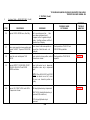
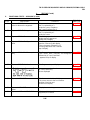
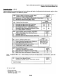
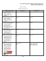
TM 11-5815-606-34, 1 November 1982, is changed as follows:
1. The attached pages were inadvertently omitted from copies of the subject publication recently distributed.
2. Insert pages as indicated below:
Remove .............................................................
None ...................................................................
None ...................... .............................................
Insert
9-1 through 9-45/9(9-46 Blank)
10-1 through 10-15/(10-16 Blank)
3. File this change sheet in .he front of publication.
By Order of the Secretaries of the Army, the Navy, and 3he Air Force:
Official:
JOHN A. WICKHAM, JR.
General, United States ,Army
Chief of Staff
ROBERT. M. JOYCE
Major General, United States Army
The Adjutant General
G. B. SHICK
Rear Admiral, United States Navy
Commander, Naval Electronic
Systems Command
Official:
JAMES P. MULLINS
General. USAF, Commander, Air Force
Logistics Command
Distribution:
To be distributed in accordance with Special Distribution List.
CHARLES A. GABRIEL, General USAF
Chief of Staff
TM 11-5815-606-34/NAVELEX 0969-LP-188-0010/TO 31W4-4-300-1
Teletype Corporation Product Service and Education Services
On the following page is a list of Teletype Corporation Product Service locations which provide
maintenance service and repair on all Teletype Corporation products. For more information call
toll free (US 800-3234226) (IL 800-9424192) 7: 00 A.M. -- 4:00 P.M. CST.
In addition, Teletype Corporation provides Customer Technical Training at its headquarters at
5555 W. Touhy Avenue, Skokie, IL in the northwest suburban area of Chicago, The training
covers the installation, maintenance and repair of all Teletype Corporation products.
Arrangements can also be made for training to be conducted at customer-selected field sites.
For information about class schedules, enrollment, tuition, on-site training or any special
training needs, please contact:
Education Services
Teletype Corporation
5555 W. Touhy Avenue
Skokie, Illinois 60077
Telephone (312) 982-3940
TLX 25-4051
TWX 901-223-3611
TM 11-5815-606-34/NAVELEX 0969-LP-188-0010/TO 31W4-4-300-1
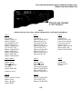
Teletype Corporation
Product Service
The Complete Resource
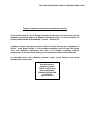
PROMPT SERVICE PERFORMED WELL AND AT A
REASONABLE COST
Even the best equipment can fail at some .time. When
failures occur, you want. prompt service, because down
time is expensive. You want service performed well and
at a reasonable cost.
With Teletype® Product Service Centers located
throughout the United States and Canada, and our
National Central Dispatch System available around the
clock, every day of the year, you know we rate customer
service as our primary goal.
A TOTAL SUPPORT EFFORT
Our service representatives are professional, employed
and trained by Teletype Corporation. They know our
equipment inside out, and can locate and repair
problems quickly and effectively.
These skilled
technicians are backed by an array of sophisticated test
equipment, a multi-million dollar parts inventory, and full
engineering support.
Only the manufacturer of
equipment being serviced can offer this total support
effort ... Teletype Corporation Product Service ... the
complete resource.
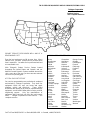
NATIONAL SERVICE NETWORK
Albany
Albuquerque
Appleton
Atlanta
Baltimore
Birmingham
Boise
Boston
Buffalo
Charleston
Charlotte
Chicago
Cincinnati
Cleveland
Colorado Springs
Columbia
Columbus
Dallas
Decatur
Denver
Des Moines
Detroit
Duluth
Durham
Eau Claire
Edison
Fairfield
Fort Lauderdale
Call Toll Free 800/323-4226 In Illinois 800/942-4192 In Canada, call416/745-9474
Greensboro
Harrisburg
Hartford
Houston
Indianapolis
Jackson
Jacksonville
Kalamazoo
Kansas City
Lansing
Little Rock
Long Island
Los Angeles
Louisville
Lubbock
Madison
Memphis
Miami
Milwaukee
Minneapolis
Mobile
Nashville
New Orleans
New York
Norfolk
Oakland
Oklahoma City
Omaha
Orange County
Orlando
Philadelphia
Phoenix
Pittsburgh
Portland
Reno
Richmond
Rochester
Sacramento
Salt Lake City
San Antonio
San Diego
Santa Clara
Seattle
Shreveport
St. Louis
Syracuse
Tampa
Toledo
Toronto
Tucson
Tulsa
Ventura
Washington
Wausau
TM 11-5815-606-34/NAVELEX 0969-LP-188-0010/TO 31W4-4-300-1
TELETYPE CORPORATION
Skokie, Illinois, U. S. A.
TEIPEST M40 SHOP MANUAL 359
Issue 3, November 1982
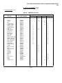
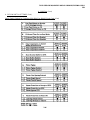
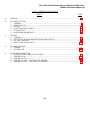
INDEX
PART
ISSUE
1
2
2
1
3
INTRODUCTION
CASSETTE DRIVE
RESERVED FOR FURTHER USE
4
5
2
2
DISPLAY 40MN202RA
OPCONS
6
2
POWER SUPPLY
7
3
CONTROLLER
8
3
9
1
CABINETS, PAPER WINDER
AND FACILITIES
SETS
10
1
MASTER COMPONEN-T PARTS INDEX
TM 11-5815-606-34/NAVELEX 0969-LP-188-0010/TO 31W4-4-300-1
TEMPEST M40 SHOP MANUAL 359
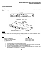
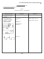
PART 1 -- INTRODUCTION
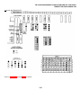
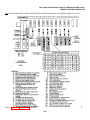
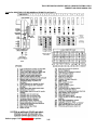
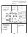
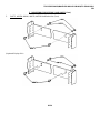
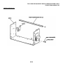
A. GENERAL
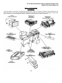
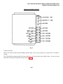
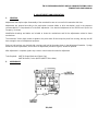
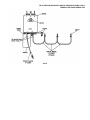
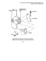
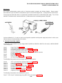
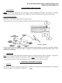
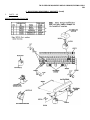
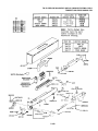
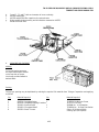
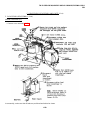
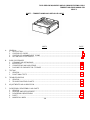
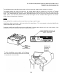
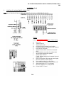
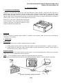
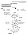
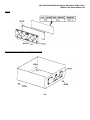
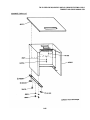
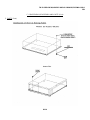
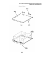
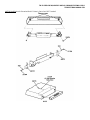
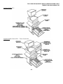
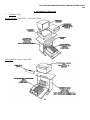
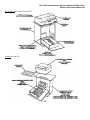
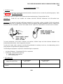
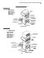
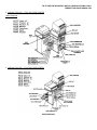
This Shop Manual is structured to facilitate maintenance and/or repair of Teletype Corporation Tempest Model 40 Sets
and Components. A KDP-RO Set arrangement detailing the components covered in Parts 2 through 8 is shown here.
Part 9 covers various set arrangements. Part 10 contains a master numerical component parts list.
1-1
TM 11-5815-606-34/NAVELEX 0969-LP-188-0010/TO 31W4-4-300-1
TEMPEST M40 SHOP MANUAL 359
A. GENERAL (Cont)
In addition to a knowledge of supplementary information and comprehensive training on Model 40 equipment, it will be
advantageous to the Shop Manual user to become thoroughly familiar with the contents before attempting maintenance
or repair. The Shop Manual should also be consulted when planning a shop in order to organize a most convenient work
place, and to assemble the necessary tools, test equipment, cleaning and packing materials, and spare parts stock.
Each part numbered 2 through 9 is prefaced with an index containing a detailed listing of section contents as follows:
A. GENERAL: Provides a brief description of equipment covered in the section and a list of tools and test equipment
required for performing all operations contained in the section.
B. SHOP PROCEDURES: Contains general information relative to repair of equipment covered in the section. Also
includes specific information regarding cleaning and refinishing, conversions from one arrangement to another, and
approved methods and materials for packing.
C. TESTING: Waveform illustrations, diagrams, adjustment and troubleshooting section references are provided as
supplementary aids to the testing procedural text.
D. TROUBLESHOOTING: Step-by-step analysis of encountered troubles are supported by charts, diagrams, and
adjustment section references. In most cases, the diagnostic steps should lead the repair person to a particular defective
component or maladjustment.
When troubleshooting the controller, the additional diagrams and circuit descriptions contained in the appropriate Wiring
Diagram Package (WDP), as listed on Pages 1-3 and 1-4, B. REFERENCE MATERIAL, will be useful.
E. ADJUSTMENTS AND LUBRICATION: Contains requirements, instructions, and descriptive views for each
adjustment and lubrication point of the subject component.
On equipment having interrelated adjustments, particularly the Model 40 Printer, a table is included listing any related
adjustments for a specific adjustment. The related adjustment table should be followed to insure proper equipment
functioning.
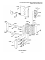
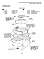
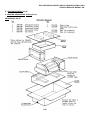
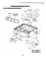
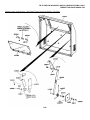
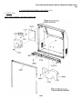
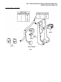
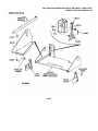
F. DISASSEMBLY/REASSEMBLY AND PARTS: Provides detailed procedures for removing and replacing various
subassemblies and individual piece parts of components covered in Parts 2 through 9. The sequenced textual
instructions are directly supported by part numbered illustrations. In addition, a complete parts listing is included that
contains a brief description of each part along with the page numbers on which the part is illustrated.
Part 10, Sets, contains additional information and illustractions relevant to interconnecting and placement of cables.
Part 11, Master Component Parts List, contains a master numerical components parts list, excluding general mounting
hardware which are listed in the component parts section for each component.
1-2
TM 11-5815-606-34/NAVELEX 0969-LP-188-0010/TO 31W4-4-300-1
TEMPEST M40 SHOP MANUAL 359
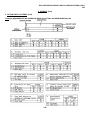
B. REFERENCE MATERIAL
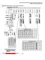
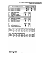
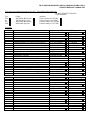
TECHNICAL DATA
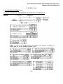
Power Source Requirements
115 Vac +10% 50/60 hertz connection to most sets is made by using a terminal block (No. 10 screws) in the interface
assembly of the set. Some sets provide a power cord equipped with a three prong plug. Refer to Part 10 for set
arrangements.
Note: When operating from a 50 cycle power source, a pulley change is required on the printer, the cassette drives and
the flexible diskette drives.
Depending on set configuration up to six ac outlets with ground connection (3 prong) is required. Each cassette drive
requires an outlet. On certain set configurations, the controller pedestal requires an outlet. The paper winder (if
supplied) requires an outlet.
DANGER: SETS MUST BE PROPERLY GROUNDED TO PREVENT SHOCK HAZARD.
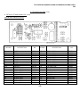
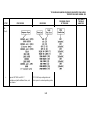
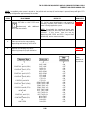
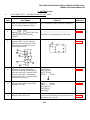
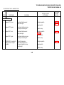
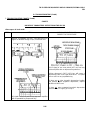
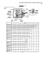
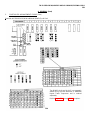
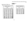
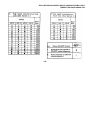
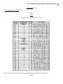
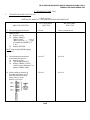
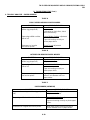
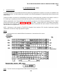
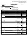
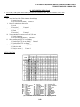
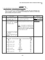
Power Consumption and Heat Dissipation
Approx
Current Draw
KDP
KD
ROP
KP
CD (each)
500 Watts
365 Watts
260 Watts
330 Watts
150 Watts
1720 BTU/Hr
1250 BTU/Hr
885 BTU/Hr
1130 BTU/Hr
367 BTU/Hr
4.5
Amps
3.35 Amps
3.15 Amps
3.65 Amps
1.0
Amps
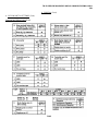
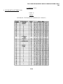
Environmental Restrictions
Environmental conditions should be maintained within the following limits to avoid damage and provide proper operation.
Environmental Condition
Temperature
Humidity
Altitude
Storage or Transportation
Min
Max
-40°F
2%
Sea Level
+150°F
95%
50,000 ft
Operation
Min
+40°F
2%
Sea Level
Max
+110°F
95%
10,000 ft
Note: As with any device that can be damaged by water, sudden temperature changes that can cause condensation
should be avoided.
Example: A device stored in subzero temperatures will collect frost when unpacked in a warm humid room.
1-3
TM 11-5815-606-34/NAVELEX 0969-LP-188-0010/TO 31W4-4-300-1
TEMPEST M40 SHOP MANUAL 359
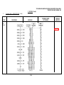
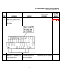
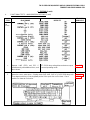
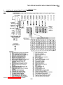
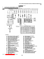
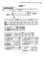
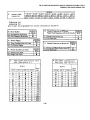
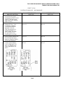
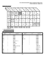
B. REFERENCE MATERIAL (Contd)
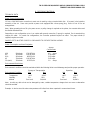
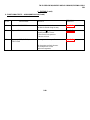
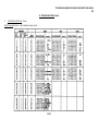
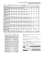
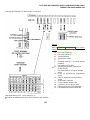
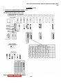
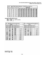
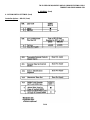
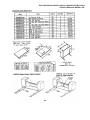
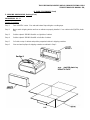
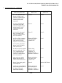
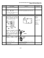
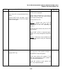
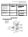
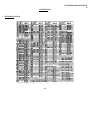
COMPONENT SPACE REQUIREMENTS AND WEIGHTS
1-4
TM 11-5815-606-34/NAVELEX 0969-LP-188-0010/TO 31W4-4-300-1
TEMPEST M40 SHOP MANUAL 359
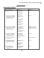
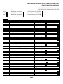
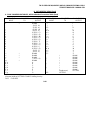
SUPPLEMENTARY MANUALS
The following manuals provide important information concerning operation, installation and field servicing of Model 40
Sets and Components. The manuals are broken down into two categories How to Operate and Installation and Service
Manuals. Listed below are manuals applicable to the Tempest Model 40 Set Configuration and the sets that they cover.
These manuals may be ordered from Teletype Corporation by the titles shown.
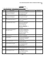
How To Operate Manuals
The "How to Operate" manuals are oriented toward the operator. The operating function and features of the various
Tempest Model 40 Set Configurations and their access or control by the operator are presented in an easy to understand
now technical format.
Manual
Title
Equipment Covered
354
How to Operate Tempest
Model 40
Set Configurations Containing the
40C430 to 40C432 Controllers (40/8A)
362
How to Operate Tempest
Model 40 ASR
Set Configurations Containing the
4OC433 Controllers (40/8A)
370
How to Operate Tempest
Model 40 Dual ASR
Set Configurations Containing the
40C434/ACW/063 Controller
405
How to Operate Tempest
Model 40/8B ASR
Set Configurations Containing the
40435/AEE/091 Controller (40/8B)
413
How to Operate Tempest
Model 40/8C
Set Configuration Containing the
40C435
445
How to Operate Tempest
Model 40/8A Ruggedized
Rack Mounted ASR
Set Configuration Containing the
40C430 to 40C432 Controllers (40/8A)
446
How to Operate Tempest
Model 40/8B and 40/8B II
KDP with Cassette Drives
Sets Configurations Containing the
40C437/AEE/091 (40/8B)
40C437/AEL/106 (40/8B II)
491
How to Operate Tempest
Model 40/8A ROP-KP-KP3
Set Configurations Containing the
40C432/AEM/103, 40C433/AEN/104,
40C438/AEP/105 Controllers
526
How to Operate Tempest
Model 40/8B I KDP with
Cassette Drives
Set Configuration Containing the
40C437/AEL/106 Controller
How to Operate Tempest
Model 40/8B II KDP with
Cassette Drives
Set Configuration Containing the
40C437/AEL/107 Controller
J
559
1-5
TM 11-5815-606-34/NAVELEX 0969-LP-188-0010/TO 31W4-4-300-1
TEMPEST M40 SHOP MANUAL 359
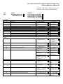
B. REFERENCE MATERIAL (Contd)
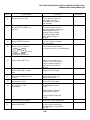
INSTALLATION AND SERVICE MANUALS
The "Installation and Service Manuals" provide in depth information required for set or station assembly, installation and
for field troubleshooting and maintenance. The subject includes?
• Installation
• Operational Checkout
• Troubleshooting
• Adjustments
• Component Access
• Routine Maintenance
The "Installation Manuals" provide information required for assembly, optioning and installation of set or station. The
"Service Manuals" provide in depth information for operational checkout and in field troubleshooting and maintenance.
Manual
Title
Equipment Covered
353
Tempest Model 40 Installation and Servicing Manual
Set Configurations Containing the
40C430 to 40C432 Controllers (40/8A)
358
Tempest Model 40 132 Column
Printer Set Installation
and Servicing Manual
Tempest 132 Column ROP Sets (40/8A)
363
Tempest Model 40 ASR Installation and Servicing Manual
Set Configurations Containing the
40C433 Controllers
371
Tempest Model 40 Dual ASR
Installation and Servicing
Manual
Set Configuration Containing the
40C434/ACW/063 Controller
404
Tempest Model 4()/8B ASR
With Cassetes Installation
Manual
Set Configuration Containing the
40C435/AEE/091 Controller (40/8B)
408
Tempest Model 40/8B ASR
With Cassettes Servicing
Manual
Set Configurations Containing the
40C435/AEE/091 Controller (40/8B)
414
Tempest Model 40 Synchronous
40/8C Installation Manual
Set Configurations Containing the
40C436/ADK/075
40C436/ADIU/095
40C436/ADN/094
40C436/ADD/093
40C436/ADA/092
Controllers (40/8C)
1-6
TM 11-5815-606-34/NAVELEX 0969-LP-188-0010/TO 31W4-4-300-1
TEMPEST MAO SHOP MANUAL 359
Manual
Title
Equipment Covered
415
Tempest Model 40 Synchronous 40/8C Service Manual
Set Configuration Containing the
40C436/ADK/075
40C436/ADU/095
40C436/ADN/094
40C436/ADD/093
40C436/ADA/092
Controllers (40/8C)
447
Ruggedized Rack Mounted
Tempest Model 40/8A Installation Manual
Set Configuration Containing the
40C430 to 40C432 Controllers (40/8A
448
Ruggedized Rack Mounted
Tempest Model 40/8A Service
Manual
Same as Manual 447
449
Ruggedized Rack Mounted
Tempest Model 40/8B and
8BII ASR With Cassette
Drives Installation Manual
Set Configuration Containing the
40C437/AEE/091 (40/8B)
40C437/AEL/107 Controllers (40/8BII)
450
Ruggedized Rack Mount Tempest Model 40/8B and 8BII
ASR With Cassette Drives
Service Manual
Same as Manual 449
492
Tempest Model 40/8A
ROP-KP-KP3 Installation
Manual
Set Configuration Containing the
40C431/AEM/103
40C432/AEN/104
40C438/AEP/105 Controllers
493
Tempest Model 40/8A
ROP-KP-KP3 Service Manual
Same as Manual 493
527
Tempest Model 40/8BI/KDP
also Tempest Model 40/8B/KDP
With Cassette Drives and
403142 Modification Kit
Set Configuration Containing the
40C437/AEL/106 Controller
528
Tempest Model 40/8BI/KDP
also Tempest Model 40/8B/KDP
With Cassette Drives and
403142 Modification Kit
Same as Manual 527
560
Tempest Model 40/8BII/KDP
With Cassette Drives Installation Manual
Set Configurations Containing
40C437/AEL/107 Controller (40/8BII)
561
Tempest Model 40/8BII/KDP
With Cassette Drives Service
Manual
Same as Manual 560
1-7
TM 11-5815-606-34/NAVELEX 0969-LP-188-0010/TO 31W4-4-300-1
TEMPEST MAO SHOP MANUAL 359
B. REFERENCE MATERIAL (Contd)
FACTORY AUTHORIZED SERVICE
Teletype Corporation maintains a nationwide Product Service Organization to serve users of Teletype Corporation
equipment. Refer to Pages 1-10 and 1-11 for details of services offered and a listing of Service Center locations.
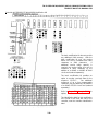
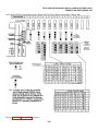
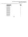
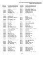
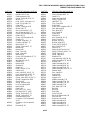
WIRING DIAGRAM PACKAGE (WDP) LISTING
The following WDPs covering the component are supplied with the set.
WDP0435
WDP0453
WDP0454
WDP0456
WDP0457
WDP0458
WDP0460
WDP0461
WDP0462
WDP0464
WDP0465
WDP0468
WDP0469
WDP0470
WDP0471
WDP0475
WDP0476
WDP0478
WDP0479
WDP0484
WDP0485
WDP0488
WDP0489
WDP0495
WDPO501
WDP0506
WDP0507
WDP0519
WDP0520
WDP0521
WDP0522
WDP0523
WDP0524
WDP0525
WDP0542
WDP0546
WDPO547
WDP0548
WDP0551
WDP0554
WDP0572
40P 20-Column Friction Feed Printer
40CAB202/RA, RO 80-Column Friction Feed Printer Cabinet
40CAB352/RA, RO 80-Column Tractor Feed Printer Cabinet
40CAB354/RA 132-Column Tractor Feed Printer Cabinet
40CAB903 Pedestals
40K103 Keyboards
40MN202/RA Display
40C430/ZZZ/000 Controller Without Cards
40P201 & 40P202/ZZ 132-Column Tractor Feed Printer Cabinet
40C431/ZZZ/000 Controller Without Cards
40C432/ZZZ/000 Controller Without Cards
40CD101 Cassette Drive (Non-Tempest)
40C430/AAT/017 Controller With Cards RCMP
40C431/ABE/026 & 40C432/ABF/027 Controllers 40/8A
40C430/ABD/025 Controller With Cards 40/8A
4016AB/001/AB Cassette Drive Set (Non-Tempest)
40C433/ZZZ/OOO Controller Without Cards
40C433/ACS/059 Controller With Cards Samson
40P154/ZZ 80-Column Tractor Feed Printer
40C434/ZZZ/000 Controller Without Cards
40C434/ACW/063 Controller With Cards TERP I
40C435/ZZZ/000 Controller Without Cards
40C435/AEB/088 Controller With Cards Samson
40C435/AEE/091 & 40C437/AEE/091 Controller With Cards 40/8B
4016RA/001/RA & 4016RB/001/RA Cassette Drives
&
M40 Paper Tape 5 & 8 Level
40C436/ADK/075 Controller With Cards 40/8C SCC
40C436/ADU/095 Controller With Cards 40/8C DCC-A
40C436/ADN/094 Controller With Cards 40/8C DCC-B
40C436/ADD/093 Controller With Cards 40/8C MCC-A
40C436/ADA/092.Controller With Cards 40/8C MCC-B
40C436/ZZZ/000 Controller With Cards
40K108 Keyboards
40C435/AEE/099 Controller With Cards 40/8D
408828 Modification Kit- 40/8B to 40/8D
40MlO3/BC Memory System
40M803/BC Memory System
40C434/AEK/101 Controller With Cards TERP II
40C437/ZZZ/000 Controller Without Cards
40K109/CAA Keyboard (40/7)
1-8
TM 11-5815-606-34/NAVELEX 0969-LP-188-0010/TO 31W4-4-300-1
TEMPEST M40 SHOP MANUAL 359
WDP0573
WDP0581
WDP0582
WDP0583
WDP0584
WDP0585
WDP0587
WDP0592
Terminal With 40C405 Controller (40/7)
40C437/AEL/106 Controller With Cards 40/8B1
40C431/AEM/103 Controller With Cards 40/8AI KP
40C432/AEN/104 Controller With Cards 40/8AI ROP
&
40C438/AEP/105 Controller With Cards 40/8AI KP3
413330 Modification Kit Clock-Phase Correction
40C437/AEL/107 Controller With Cards 40/8BII
1-9
TM 11-5815-606-34/NAVELEX 0969-LP-188-0010/TO 31W4-4-300-1
TEMPEST M40 SHOP MANUAL 359
PART 2 -- TEMPEST MODEL 40 CASSETTE DRIVE
INDEX
A.
GENERAL
1.
DESCRIPTION ......................................................................................................
2.
TOOLS, TEST EQUIPMENT AND MISCELLANEOUS............................................
3
4
SHOP PROCEDURES
1.
GENERAL...............................................................................................................
2.
CLEANING..............................................................................................................
3.
INSPECTION .........................................................................................................
4.
MARKING AND PACKING .....................................................................................
5
5
7
8
TESTING
1.
GENERAL ..............................................................................................................
2.
PRELIMINARY CHECKS .......................................................................................
3.
OFF-LINE CHECKOUT PROCEDURE ...................................................................
4.
MONITOR TAPE CASSETTE CHECKOUT ............................................................
5.
ON-LINE CHECKOUT.............................................................................................
6.
CASSETTE TEST PROGRAMS .............................................................................
11
11
11
11
26
29
D.
TROUBLESHOOTING......................................................................................................
1.
GENERAL...............................................................................................................
2.
ERROR ANALYSIS.................................................................................................
3.
COMPONENT ANALYSIS.......................................................................................
4.CIRCUIT CARD ANALYSIS (410043)............................................................................
5.
CIRCUIT CARD ANALYSIS (410764). ....................................................................
6.
FUNCTIONAL SCHEMATICS. ................................................................................
40
40
44
47
53
57
86
E.
ADJUSTMENTS AND LUBRICATION ..............................................................................
1.
GENERAL...............................................................................................................
2.
ASSEMBLIES .........................................................................................................
3.
CASSETTE HOLDER ADJUSTMENTS...................................................................
4.
DRIVE MECHANISM ADJUSTMENTS....................................................................
5.
410764 CIRCUIT CARD ADJUSTMENT .................................................................
6.
CASSETTE DRIVE LUBRICATION.........................................................................
93
93
93
95
106
110
111
B.
C.
2-1
TM 11-5815-606-34/NAVELEX 0969-LP-188-0010/TO 31W4-4-300-1
TEMPEST M40 SHOP MANUAL 359
PART 2 -- TEMPEST MDDEL 40 CASSETTE DRIVE (Contd)
INDEX (Contd)
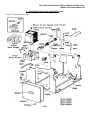
F.
DISASSEMLY/REASSEMLY AND PARTS .......................................................................
1.
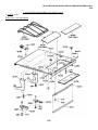
REMOVAL AND REPLACEMIT OF UPPER CABINET ASSEMBLY .......................
2.
SUBASSEMBLY IDENIFICATION...........................................................................
3.
DISASSEMBLY/REASSEMBLY DRIVE ..................................................................
4.
DISASSEMBLY/REASSEMBLY SSI/AC INTERFACE ............................................
5.
PARTS ...................................................................................................................
6.
CONPONENT PARTS LIST....................................................................................
2-2
PAGE
114
114
116
116
121
135
144
TM 11-5815-606-34/NAVELEX 0969-LP-188-0010/TO 31W4-4-300-1
TEMPEST M40 SHOP MANUAL 359
PART 2 -- TEMPEST MODEL 40 CASSETTE DRIVE
A. GENERAL
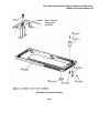
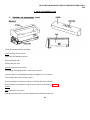
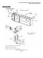
1. DESCRIPTION
The function of the Tempest Model 40 Cassette Drive is to record (store) and retrieve data on a magnetic tape media.
The cassette drive accomodates a "Phillips" type cassette which conforms with the exception of tape length to the
proposed ANSI standard for digital cassettes for the purpose of storing data. The cassette drive is designed to be used
with Model 40 equipment containing a C400 or equivalent controller. Transmission of data and control signals between
the cassette drive and the controller conform to the Teletype Standard Serial Interface (SSI), system. The cassette drive
has no local controls and functions only in response to commands from the associated controller.
Tape movement is accomplished by means of a synchronous motor and a reel to reel drive arrangement wherein the
drive (forward) and rewind (reverse) shafts are controlled by electromechanical clutches and electromagnetic brakes.
The cassette drive is designed to operate as a block device. Operation is synchronous within a block and asynchronous
by block. As such, transmission to or from the cassette drive may be selected as required by the controller, but once the
transmission has started the entire block must be transmitted. Tempest applications of the cassette drive utilize a 256
SSI word (512 ASCII characters) block size. The cassette storage capacity with the 256 SSI word block format is 500
blocks or 256,000 characters.
The cassette drive contains a single control logic circuit card which contains all logic required to control the cassette
drive. The control logic card of the cassette drive receives commands from the controller and translates them into the
appropriate signals to control the clutches, brakes and the read/write head. The control logic card interprets the input
from cassette-in-place and write inhibit switches and the BOT photo sensor and translates them into the proper signals to
the controller. It also provides drive for the BOT sensor lamp and the status (Run-Stop) lamp.
The cassette drive utilizes a single two channel read/write magnetic tape head to record and read data on the magnetic
tape. Both channels are used during either the read or write operations.
The cassette drive contains a power supply to supply the voltage and current required by the cassette drive control logic
card. The ac power to the cassette drive motor and power supply is controlled by an attendant accessible switch.
Refer to WDP 0501 for a general circuit description with block diagram and for further details of the major component
functions.
The cassette drive is designed for operation with a supply voltage of 115 V ac ±10 percent 50 or 60 hertz ±5 percent.
Operating power is 105 watts and heat generation is 367 BTU per hour. When operating on 50 hertz power, a pulley
change is required at the cassette drive motor.
2-3
TM 11-5815-606-34/NAVELEX 0969-LP-188-0010/TO 31W4-4-300-1
TEMPEST M40 SHOP MANUAL 359
A. GENERAL (Contd)
2. TOOLS, TEST EQUIPMENT AND MISCELLANEOUS
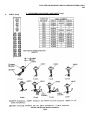
Tools
The tools listed below are supplementary to common types such as pliers, screwdrivers, wrenches, etc and may be
procured locally or ordered from Teletype Corporation.
NOTE:
When ordering parts, prefix each part number with the letters "TP" unless otherwise specified.
Description
Part No.
• Pull Spring Hook
• Nut Driver Wrench 1/4 Inch
• Nut Driver Wrench 5/16 Inch
• Nut Driver Wrench 3/16 Inch
• Terminal Extractor
• Allen Wrench 0.050 Inch
• Allen Wrench 0.078 Inch
• Ruler 6 inch
• Gauge (Brake and Clutch Gap)
• Wrench, Drive (402274/402275 Drive Hubs)
• Soldering Iron, Weller Model W-MCP-750 With MP2C Tip,
or Equivalent (Procure Locally)
• Desoldering Tool, EDSYN Model MMS005 Soldapullt ® ,
or Equivalent (Procure Locally)
75765
89954
89955
125752
182697
104457
110271
95960
406130
406131
Test Equipment
The following equipment or equivalent is required for testing, troubleshooting and adjusting the cassette drive.
• Volt-Ohm-Millimeter, Triplett Model 630 APL
• Digital Multimeter, Fluke Model 8100A
• Oscilloscope, Tektronix Model 7904 E/W:
2 -- 7A16A Single Trace Amplifiers
1 -- 7B70 Time Base Unit
2 -- RX10 Circuit Probes
• High Voltage DC Breakdown Tester, Slaughter Company Model 108-2.5MW
• Tempest Model 40 KDP Set E/W 40C433/ACS/059
• Cassette Drive Program
The test program used with a C400 controller provides a 38 step program for recording, reading and verifying
approximately ten million characters on a block by block basis.
The Cassette Drive Test Program is available from:
Teletype Custom Systems Division
5555 Touhy Avenue
Skokie, Illinois 60677
312-982-2000
• Cassette Drive Test Program - CP10.006
• Modified 410504 Circuit Card With Cassette Tape
• Loader EPROMS - CP10.006.010
2-4
TM 11-5815-606-34/NAVELEX 0969-LP-188-0010/TO 31W4-4-300-1
TEMPEST 1M40 SHOP MANUAL 359
Miscellaneous
Grease -- 145867 (4 ounce can) or 143484 (1 pound can)
Oil -- 88970 (1 quart can)
Degreaser (Freon TF) -- 337449 (6 ounce aerosol can)
Tape Head Cleaner -- 337401 (6 ounce aerosol can)
B. SHOP PROCEDURES
1. GENERAL
This section details the cleaning, refinishing and inspection procedures to be followed prior to testing and troubleshooting
the cassette drive. In many cases, careful inspection will save later troubleshooting by revealing broken or loose
connections, damaged components, possible short circuits, etc.
Refer to Page 114 F. DISASSEMBLY/REASSEMBLY AND PARTS whenever detailed information on removing cassette
drive components is required.
The packing materials detailed in this section are designed for protection against damage from rough handling in
shipping.
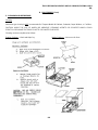
2. CLEANING
Immersion type cleaning is NOT recommended for the cassette drive.
CAUTION:
AVOID THE USE OF HARSH OR ABRASIVE CLEANING AGENTS OR SOLVENTS WHICH COULD
SCRATCH OR DAMAGE THE EXTERNAL SURFACES OF THE CASSETTE DRIVE CABINET.
Exterior
Remove upper cabinet assembly.
(2) When necessary a very weak solution of mild
detergent may be used to remove stubborn dirt, grease,
or finger prints.
(3) Vacuum louvers in rear of cabinet to remove all dust.
Clean all surfaces as follows:
(1) Wipe with soft cloth moistened with water and wrung
almost dry.
2-5
TM 11-5815-606-34/NAVELEX 0969-LP-188-0010/TO 31W4-4-300-1
TEMPEST 1M40 SHOP MANUAL 359
B. SHOP PROCEDURES (Contd)
2. Cleaning (Contd)
Interior
Remove cassette if present from drive mechanism before cleaning is started.
(1) Clean drive mechanism by using a vacuum, brushing or wiping away dust and foreign material.
CAUTION:
EXTREME CARE SHOULD BE EXERCISED WHEN CLEANING IN THE AREA OF THE TAPE
READ/WRITE HEAD TO PREVENT DAMAGE TO THE HEAD PARTICULARLY SCRATCHES OR DENTS ON THE
TAPE HEAD POLE PIECES.
(2) Clean mating surfaces of the armature and rotor faces; place a small piece of paper saturated with 337401
recording head cleaner between the armature and rotor faces of each clutch assembly; apply pressure to each
face; withdraw paper from between the armature and rotor. Repeat for each pole face until the withdrawn paper
is clean.
(3) Using 337401 recording head cleaner and a cotton swab, clean the tape head, hub drivers and cassette locating
pins.
(4) Check 403238 tape cleaner, if dirty replace.
2-6
TM 11-5815-606-34/NAVELEX 0969-LP-,188-0010/TO 31W4-4-300-1
TEMPEST M40 SHOP MANUAL 359
3. INSPECTION
Interior
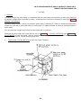
a. Check that the motor drive belt and the "O" ring are present and free from cracks and are not frayed.
b. Check that all three pullies and both armatures turn when motor is turned by hand at fan end. (Turn clockwise as
viewed from fan end.)
c. Check that power supply fuse is present, not blown and correct value (0.6 amp SL-BL).
d. Check that plug P1, P2, P4A and P4B are fully seated in their respective connectors on the 410764 control logic
circuit card. Connectors are under the cassette drive base plate.
e. Remove cassette if present.
2-7
TM 11-5815-606-34/NAVELEX 0969-LP-188-0010/TO 31W4-4-300-1
TEMPEST 1M40 SHOP MANUAL 359
B. SHOP PROCEDURES (Contd)
3. INSPECTION (Contd)
Interior (Contd)
f. Check that the tape load connector is fully seated in
the tape head and is orientated in the correct direction.
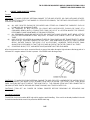
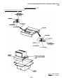
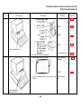
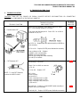
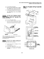
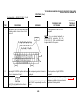
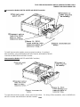
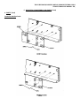
4. MARKING AND PACKING
Packing
Factory-type packing may be duplicated by ordering material shown below and applying as follows. PK designated items
should be ordered from Teletype Corporation.
Qty.
1
1
8
1
1
1
2
-
Materials Required
10774PK Corrugated Carton
9861PK Corrugated Carton
28278PK Corner Details
28218PK Detail A
28218PK Detail B
23457PK Plastic Bag
27643PK Labels
21719PK Tape (as required)
21632PK Tape (as required)
21480PK Tape (as required)
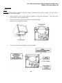
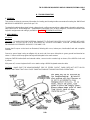
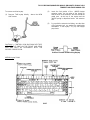
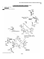
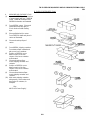
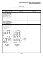
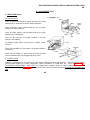
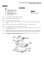
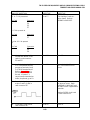
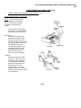
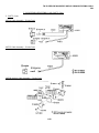
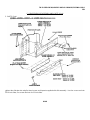
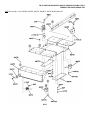
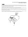
(1) Carefully turn set upside down. Apply a strip of 21480PK tape on either side of unit base. Each tape strip must
overlap both the base and cover side plate, as shown. Turn set right side up.
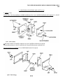
(2) Apply two bands of 21632PK tape around set as shown. Apply a third strip of tape across top and front of set to
hold lid down.
(3) Place set in a 23457PK plastic bag. Leave line cord extended outside of bag.
2-8
TM 11-5815-606-34/NAVELEX 0969-LP-188-0010/TO 31W4-4-300-1
TEMPEST M40 SHOP MANUAL 359, 2-9
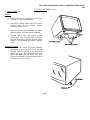
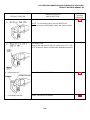
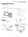
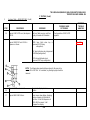
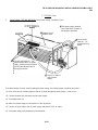
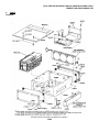
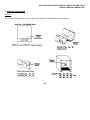
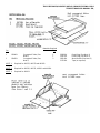
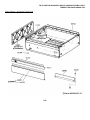
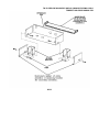
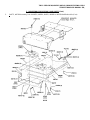
(4) Position a 28218PK Detail A on right side of unit and a 28218PK Detail B on left side of unit as shown. Position
line cord on top of unit.
(5) Form a 9861PK carton. Close and seal bottom flaps with a strip of 21719PK tape applied at the center seam and
extending at least three inches up the sides of the carton.
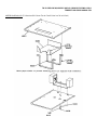
(6) Place set and details in the carton. Close and seal top flaps of carton as outlined in Step 5. Apply a 27643PK
label to upper left hand portion of top of carton.
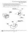
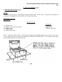
(7) Form a 10774PK carton. Close and seal bottom of flaps with three strips of 21719PK tape. Apply tape to center
and end seams.
(8) Secure a 28278PK detail to each of the four bottom corners of the inner carton by means of the pressure
sensitive tape on each detail.
(9) Place carton and details in the outer carton.
(10) Position a 28278PK detail on each of the four top corners of the inner carton.
(11) Close and seal top flaps of carton and seal as indicated in Step 7.
(12) Moisten and apply a 27643PK label to upper left hand portion of top of carton.
2-9
TM 11-5815-606-34/NAVELEX 0969-LP-188-0010/TO 31W4-4-300-1
TEMPEST 1M40 SHOP MANUAL 359
B. SHOP PROCEDURES (Contd)
4. MARKING AND PACKING (Contd)
Packing (Contd)
2-10
TM 11-5815-606-34/NAVELEX 0969-LP-188-0010/TO 31W4-4-300-1
TEMPEST M40 SHOP MANUAL 359
C. TESTING
1. GENERAL
Testing of the Tempest Model 40 Cassette Drive Units is accomplished with the cassette drive(s) connected as part of a
Tempest C400 Station. The test is performed in two stages:
(1) Off-line/on-line checkout,
(2) Functional test using the Teletype Custom Systems Division CP10.006 Cassette Test Program.
Each test procedure should be performed from start to finish with no omissions.
Whenever the cassette drive fails a particular test, refer to Page 2-40, D. TROUBLESHOOTING and/or Page 2-93, E.
ADJUSTMENTS AND LUBRICATION to locate the trouble. After the trouble has been located and corrected, repeat the
test that disclosed the trouble and if found OK, resume testing from that point.
NOTE: When ordering replaceable parts or components, unless otherwise specified, prefix each part number with the
letters "TP' (ie, TP410055).
An operational checkout should be performed upon installation or on trouble calls.
If the indicated response is not obtained in any step of a checkout procedure, repeat the step to make sure that the
procedure has been performed correctly. If the results are still unsatisfactory, perform the indicated trouble analysis.
Always perform the checkout in the order given in the chart,
The trouble analysis steps are based on satisfactory results of all previous steps.
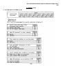
2. PRELIMINARY CHECKS
Before turning on any equipment, check the following:
a.
b.
c.
d.
e.
f.
g.
Are all circuit cards and cable connectors fully seated?
Are all fuses in place?
Are all cabinet lids and pedestal doors closed?
Do all printers have paper and ribbon properly installed?
Is the station connected to a properly grounded ac service?
Have the station options been installed and are they properly recorded?
Prior to applying ac power to the controller, insure that power is on to the tape cassette drives and the
cassette is in the unlatched (cassettes disengaged) position.
h. Insure that all tape cassettes are properly formatted, each tape cassette must be placed in the receive tape
cassette drive and the erase function performed. The erase function must be performed prior to the offline checkout of the cassette drive. Refer to How to Operate Manual 405, Page 19 for procedure to erase
cassettes.
2-11
TM 11-5815-606-34/NAVELEX 0969-LP-188-0010/TO 31W4-4-300-1
TEMPEST M40 SHOP MANUAL 359
C. TESTING (Contd)
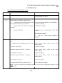
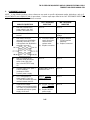
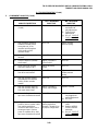
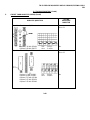
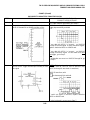
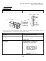
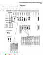
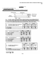
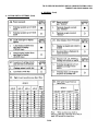
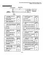
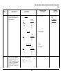
3. OFF-LINE CHECKOUT PROCEDURE
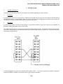
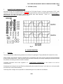
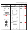
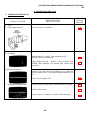
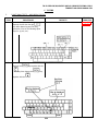
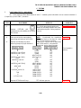
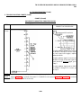
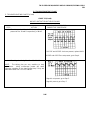
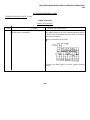
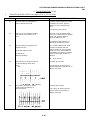
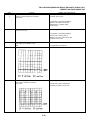
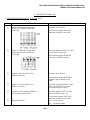
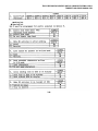
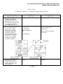
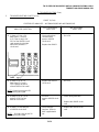
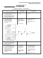
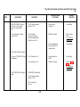
NOTE: Immediately when power is turned on, various LED displays will be lighted on the opcon depending upon
station type and applicable controller. See appropriate service manual for operation of particular stations.
STEP
1
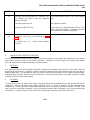
2
PROCEDURE
Depress CNTRL MODE keytop.
RESULTS
CNTRL MDE lamp lights and the
following message appears on the
display.
Number indicates cassette drive assigned for that function.
ST = Send Tape
RT = Receive Tape
MT = Monitor Tape
0 will appear if no cassette drive is available for that function.
LOCAL CHECKOUT KDP2 AND KDPM3
Using cursor positioning key
(1)position
cursor to the first underline
to the right of 2.
(2) Type an upper case X.
Cursor moves under direction of
cursor key.
X appears, cursor moves one
space to the right.
2-12
TM 11-5815-606-34/NAVELEX 0969-LP-188-0010/TO 31W4-4-300-1
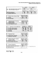
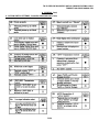
TEMPEST M40 SHOP MANUAL 359
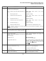
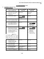
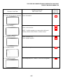
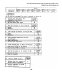
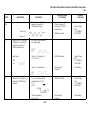
STEP
2
(Contd)
PROCEDURE
RESULTS
Depress LINE FEED key.
X remains, cursor returns to its original position.
3
Depress CNTRL MDDE key.
Message on screen extinguishes, cursor goes to
home position.
4
Enter a line of "Quick Brown Fox". End line with
ETX. Enter several new lines. Enter a line of "Now
is the time" end with ETX.
Message appears on display as typed.
Depress HOME.
Cursor goes home.
Depress PTR LCL.
PTR LCL lamp lights.
Depress REC TAPE LCL.
REC TAPE lamp lights.
Depress DISP SEND.
DISP SEND lamp lights.
Depress DISP LCL.
DISP LCL lamp lights.
Cursor moves across message and stops at
character position after first ETX.
Printer motor starts and copies message. REC
TAPE positions cassette to next available recording
block and records message.
When cursor reaches the first ETX, DISP LCL will
extinguish.
2-13
TM 11-5815-606-34/NAVELEX 0969-LP-188-0010/TO 31W4-4-300-1
359
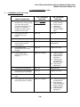
C. TESTING (Contd)
3.
OFF-LINE CHECKOUT PROCEDURE (Contd)
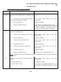
STEP
5
PROCEDURE
RESULTS
Depress DISP LCL again.
Cursor moves from present position to next ETX.
Printer and REC TAPE copy message as in Step 4.
NOTE: If terminal is optioned for home on send,
the cursor will go to the HOME position and the first
message will be sent again.
Depress PTR LCL.
PTR LCL lamp extinguishes.
Depress DISP SEND.
DISP SEND lamp extinguishes.
Depress REC TAPE LCL.
REC TAPE LCL lamp extinguishes.
7
Depress CNTRL MODE key.
Prepared message extinguishes, and control mode
message appears.
8
(1)
Using cursor positioning key, position cursor
over X placed in line 2.
Cursor moves under direction of cursor control
keys.
(2)
Depress SPACE BAR key.
X is deleted.
(3)
Depress LINE FEED key.
Cursor returns to its original position.
6
9
Depress CNTRL MDDE key.
Control mode message extinguishes, and original
typed message appears. Cursor in HOME position.
2-14
TM 11-5815-606-34/NAVELEX 0969-LP-188-0010/TO 31W4-4-300-1
TEMPEST M40 SHOP MANUAL 359
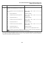
STEP
10
PROCEDURE
RESULTS
Depress PTR LCL.
PTR LCL lamp lights.
Depress REC TAPE LCL.
REC TAPE LCL lamp lights.
Depress DISP SEND.
DISP SEND lamp lights.
Depress DISP LCL.
DISP LCL lamp lights
Cursor moves through messages until first ETX is
reached.
Printer and REC TAPE copy message.
DISP LCL lamp extinguishes when the first ETX is
reached.
Depress DISP LCL again.
See Note in Step 5.
Cursor moves to next ETX, and DISP LCL lamp
extinguishes.
Depress PTR LCL.
PTR LCL lamp extinguishes.
Depress REC TAPE LCL.
REC TAPE LCL lamp extinguishes.
Depress DISP SEND.
DISP SEND lamp extinguishes.
12
Depress CNTRL MDDE key.
Typed message extinguishes, and control message
appears on display.
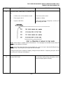
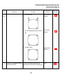
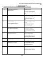
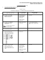
13
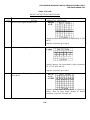
Using the cursor control keys, position the cursor
over the underline next to 7. Type an upper case X.
Cursor moves under control of cursor control keys.
X appears on display.
Depress LINE FEED key.
The control mode message extinguishes the REC
TAPE rewinds and the following appears on the
display.
11
NOTE: When listing is complete, alarm will sound once. If no messages are recorded on tape, alarm will
sound once and display will be blank.
2-15
TM 11-5815-606-34/NAVELEX 0969-LP-188-0010/TO 31W4-4-300-1
359
C. TESTING (Contd)
3.
OFF-LINE CHECKOUT PROCEDURE (Contd)
STEP
PROCEDURE
RESULTS
14
Depress SPACE BAR.
Tape heading listing extinguishes, and control mode
message appears on display.
15
Using the cursor control keys, position cursor.
(1)
To character space to left of Receive Tape
Block Number and enter an upper case R.
Cursor moves under control of cursor control key.
R appears on display.
(2)
Position cursor over X in line 7 and depress
Space Bar.
X is deleted from display.
(3)
Cursor returns to its original position. REC TAPE
rewinds.
Depress LINE FEED.
When rewind is complete.
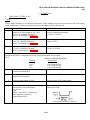
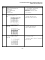
4.
000 REC TAPE BLOCK NUMBER is
displayed.
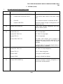
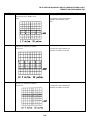
16
Using the cursor control keys, or CURSOR TAB
key.
(1) Position cursor to underline next to 11 in line
11.
Cursor moves under
positioning keys.
control
of
the
cursor
(2) Enter an upper case X.
X appears on display.
(3) Position cursor to 1 after ST = 1 in line 11.
Cursor moves under
positioning keys.
control
of
the
cursor
(4) Overwrite the 1 with a 2.
2 appears on display
(5) Position cursor to 2 after RT = 2 in line 11.
Cursor moves under
positioning keys.
control
of
the
cursor
(6) Overwrite the 2 with a 1.
1 appears on display.
(7) Depress LINE FEED key. position in line 1.
Cursor returns to its original
NOTE: The above procedure has reassigned Cassette 1 as the receive cassette and Cassette 2 as the
send cassette.
2-16
TM 11-5815-606-34/NAVELEX 0969-LP-188-0010/TO 31W4-4-300-1
TEMPEST M40 SHOP MANUAL 359
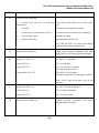
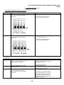
STEP
PROCEDURE
RESULTS
17
Using the cursor control keys, or CURSOR TAB
key.
(1)
Position cursor to first underline in row 6.
Cursor moves under control.
(2)
Enter a upper case X.
X appears on display.
(3)
Depress LINE FEED.
Control mode message extinguishes, and the send
tape headings are listed.
NOTE: When listing is complete, alarm will sound once. If no messages are recorded on tape, alarm will
sound once and display will be blank.
NOTE: At any time during the listing of tape heading, the space bar may be depressed halting the tape
heading listing. Depressing the space again will start the listings.
If listing exceeds 24 lines (capacity of display), listing will stop at 24th line. Depressing the space bar will
cause the next 24 listings to be displayed.
18
Depress SPACE BAR.
The send tape heading listing extinguishes, and the
control message appears on display.
2-17
TM 11-5815-606-34/NAVELEX 0969-LP-188-0010/TO 31W4-4-300-1
359
C. TESTING (Contd)
3.
OFF-LINE CHECKOUT PROCEDURE (Contd)
STEP
PROCEDURE
RESULTS
19
Using the cursor control keys or CURSOR TAB key.
(1)
Position cursor over first 0 in line 3.
Cursor moves under control of the cursor control
keys.
(2)
Enter 001.
The current block number is overwritten with 001.
(3)
Depress LINE FEED.
Send block number changes counting down to 000
and then up to 001.
20
Depress CNTRL MDE key.
Control mode message extinguishes and cursor
returns to HOME position.
21
Depress DISP LCL.
DISP LCL lamp lights.
Depress REC TAPE LCL.
REC TAPE LCL lamp lights.
Depress PTR LCL.
PTR LCL lamp lights.
Depress SEND TAPE LCL.
The SEND TAPE transfers all its messages (4).
The display will copy to first ETX, and DISP LCL will
extinguish. The printer and REC TAPE will copy all
messages.
The SEND TAPE LCL lamp will extinguish when the
message transfer is completed.
22
23
Depress REC TAPE LCL.
REC TAPE LCL lamp extinguishes.
Depress PTR LCL.
PTR LCL lamp extinguishes.
Depress HOME.
Cursor goes to HOME position.
Depress CLEAR.
Message is cleared from display.
Depress CNTRL MDDE key.
Send tape message on display extinguishes, and
control mode message appears.
2-18
TM 11-5815-606-34/NAVELEX 0969-LP-188-0010/TO 31W4-4-300-1
TEMPEST M40 SHOP MANUAL 359
STEP
24
PROCEDURE
RESULTS
Using the cursor control keys.
(1)
Position cursor over first 0 in send tape
block number.
Cursor moves under control of the cursor control
keys.
(2)
Enter 001.
001 appears in send tape block number.
(3)
Position cursor over under-line in line 8.
Cursor moves under control of cursor control key.
(4)
Enter an upper case X.
X appears on display.
(5)
Depress LINE FEED.
Send tape rewinds to block 001.
DISP LINE and DISP LCL lamps start flashing
indicating monitor data on display mode.
25
Depress CNTRL NMDE key.
Control mode message extinguishes and blank
display with cursor in HOME position is displayed.
26
Depress REC TAPE LCL.
REC TAPE LCL lamp lights.
Depress PTR LCL.
PTR LCL lamp lights.
Depress DISP LCL.
DISP LCL lamp stays on steady
DISP LINE continues to flash.
Depress SEND TAPE LCL.
SEND TAPE LCL lamp lights.
Send tape transmits all four messages recorded on
it.
Printer, receive tape and monitor copy all four
messages.
27
28
Depress REC TAPE LCL.
REC TAPE LCL lamp extinguishes.
Depress PTR LCL.
PTR LCL lamp extinguishes.
Depress DISP LCL.
DISP LCL starts to flash.
Depress CNTROL MODE key.
Received message extinguishes,
message appears on display.
2-19
and
control
TM 11-5815-606-34/NAVELEX 0969-LP-188-0010/TO 31W4-4-300-1
359
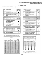
C. TESTING (Contd)
3.
OFF-LINE CHECKOUT PROCEDURE (Contd)
STEP
PROCEDURE
29
Using the cursor control keys or CURSOR TAB key.
30
RESULTS
(1)
Position cursor over P in line 3.
Cursor moves under control of the cursor control
keys.
(2)
Enter an upper case R.
R overwrites P.
(3)
Position cursor over X in line 8, depress
SPACE BAR.
X is deleted from display.
(4)
Position cursor to first underline in line 9.
Enter three upper case Xs.
XXX appears on display.
(5)
DISP LINE and DISP LCL lamps stop flashing and
are extinguished. Send and receive tapes rewind.
*** appear in the tape block numbers while rewind is
completed, 000 appears in the receive tape block
number. 000 appears in the send block number.
Depress LINE FEED.
Using the cursor control keys or CURSOR TAB key.
(1)
Position the cursor to the underline next to
11 in line 11.
Cursor moves under
positioning keys.
(2)
Enter an upper case X.
X appears on display.
(3)
Position the cursor to the 2 after ST=2.
Cursor moves under
positioning keys.
(4)
Overwrite the 2 with a 1.
1 appears on display.
(5)
Position the cursor to the 1 after RT=1.
Cursor moves under
positioning keys.
(6)
Overwrite the 1 with a 2.
2 appears on display.
(7) Depress the LINE FEED key.
control
of
the
cursor
control
of
the
cursor
control
of
the
cursor
Cursor returns to its original position in line 1.
NOTE: The above procedure has reassigned Cassette 1 as the send cassette and Cassette 2 as the
receive cassette.
2-20
TM 11-5815-606-34/NAVELEX 0969-LP-188-0010/TO 31W4-4-300-1
359
STEP
PROCEDURE
RESULTS
31
Using the cursor positioning keys or CURSOR TAB
key, position the cursor to the first underline
following 9 in line 9.
Cursor moves under control of the cursor position
keys.
Enter three upper case Xs.
XXX appears on display.
Depress the LINE FEED key.
Cursor returns to its original position in line 1. REC
TAPE (Cassette 2) rewinds. *** appears in the tape
block number while rewind is taking place.
32
For KDPM2 sets, go to 5. On-Line Checkout, Page
2-82.
For KDPM3 sets, to 4.
Checkout.
4.
Monitor Tape Cassette
MONITOR TAPE CASSETTE CHECKOUT
The off-line checkout procedure of Part C does not check the operation of the monitor tape cassette since the monitor
tape cassette (Cassette 3) has no local mode of operation. To perform an on-line check of the monitor tape cassette
drive, two methods are available, depending on system protocol.
1.
METHOD 1
If the system provides for on-line testing of terminals, a sample test message may be sent to the Test Center. After the
test message has been sent, Cassette 3 should be rewound, reassigned to the send cassette and a local send tape to
display transfer done. The message can then be checked to insure the monitor tape correctly copied the sent message.
Rewind the tape, reassign Cassette 3 to be the receive tape. Perform the erase function on Cassette 3 and then reassign
Cassette 3 to be the monitor tape cassette.
2.
METHOD 2
If system protocol does not allow on-line testing, temporarily disconnect the terminal from the line by removing the line
connections. Add the half-duplex strap between terminals 2 and 3 of TB101 of interface, if it was removed during
installation. For this test, the clear-to-send input must be turned on or temporarily remove the 303181 or 303184 circuit
card in slot Z4 of the interface assembly. Now, the following procedure may be followed to check out the monitor tape
cassette drive. During this test, the set must be in the manual mode of operation (POLL/SEL lamp not lit).
2-21
TM 11-5815-606-34/NAVELEX 0969-LP-188-0010/TO 31W4-4-300-1
359
C. TESTING (Contd)
4.
MONITOR TAPE CASSETTE CHECKOUT (Contd)
STEP
PROCEDURE
RESULTS
1
Prepare a test message on display in keyboarddisplay mode (DISP LINE, DISP LCL and DISP
SEND lamps not lit). Start message with SOH. End
message with ETX. Home cursor.
Message appears on display as typed on keyboard.
2
Depress PTR LINE.
PTR LINE lamp lights.
Depress DISP SEND.
DISP SEND lamp lights.
Depress DISP LINE.
DISP LINE lamp lights. Cursor moves through
message and stops at character position after ET,.
Printer motor starts and printer copies message.
Display lamps will extinguish, if Option U2 is
installed. The DISP SEND lamp will extinguish if
Option U1 is installed.
Depress DISP LINE if lit.
DISP LINE lamp extinguishes.
Depress CNTRL MODE.
Test message disappears from display and control
message appears.
3
4
Using cursor control keys or CURSOR TAB key.
(1)
Position cursor to the character position to
the left of the tape block number in line 5.
Cursor moves under
positioning keys.
(2)
Enter an upper case R.
R appears on display.
(3)
Depress the LINE FEED key.
Cursor returns to its original position in line 1. ***
appears in the monitor tape block while the monitor
tape is rewinding. When the rewind is completed,
000 appears in the monitor tape block.
2-22
control
of
the
cursor
TM 11-5815-606-34/NAVELEX 0969-LP-188-0010/TO 31W4-4-300-1
TEMPEST M40 SHOP MANUAL 359
STEP
5
PROCEDURE
RESULTS
Using the cursor positioning keys.
(1)
Position cursor to the under line after 11 in
line 11.-
Cursor moves
positioning key.
under
control
of
the
cursor
(2)
Enter an upper case X.
X appears on display.
(3)
Position cursor to the 1 after ST=1.
Cursor moves under
positioning keys.
control
of
the
cursor
(4)
Overwrite the 1 with a 3.
3 appears on display.
(5)
Position the cursor to the 3 after MT=3.
Cursor moves under
positioning keys.
control
of
the
cursor
(6)
Overwrite the 3 with a 1.
1 appears on display.
(7)
Depress the LINE FEED key.
Cursor returns to its original position in line 1.
NOTE: Cassette 3 (monitor) has now been reassigned as the send tape and Cassette 1 has been
reassigned as the monitor tape.
6
Enter block number of test message (001 if cassette
was not used before) in line 3. Depress LINE FEED
Send tape cassette positions to test message.
7
Depress CNTRL MDDE.
Position cursor to the beginning of the line after
original message.
Control message disappears and original test
message appears.
Depress DISP LCL.
DISP LCL lamp lights.
SEND TAPE LCL lamp lights.
Depress SEND TAPE LCL.
Test message appears on display below original
message. These messages should be the same,
except line feeds (
) which were sent and stored
on monitor tape are displayed as
,
( )
Depress the SEND TAPE LCL key.
SEND TAPE LCL lamp extinguishes.
Home cursor.
Cursor goes to HOME position.
Depress CLEAR key.
Both messages are cleared from display.
Depress CNTRL MODE key.
Control message appears on display.
8
9
2-23
TM 11-5815-606-34/NAVELEX 0969-LP-188-0010/TO 31W4-4-300-1
359
C. TESTING (Contd)
4.
MONITOR TAPE CASSETTE CHECKOUT (Contd)
STEP
PROCEDURE
10
Using the cursor positioning key or CURSOR TAB
key.
11
RESULTS
(1)
Position the cursor to the character space to
the left of the send tape block number.
Cursor moves
positioning key.
under
control
of
the
cursor
(2)
Enter an uppercase R.
R appears on display.
(3)
Depress the LINE FEED key.
Cursor returns to its original position in line 1. ***
appears in the send tape block number while the
send tape is rewinding. 000 appears in the send
tape block number when rewind in completed.
Using cursor positioning keys,
(1)
11.
Position cursor to underline after 11 in line
Cursor moves under
positioning keys.
control
of
the
cursor
(2)
Enter an uppercase X.
X appears on display.
(3)
Position cursor to the 3 after ST=3.
Cursor moves under
positioning keys.
control
of
the
cursor
(4)
Overwrite the 3 with a 2.
2 appears on display.
(5)
Position the cursor to the 2 after RT=2.
Cursor moves under
positioning keys.
control
of
the
cursor
(6)
Overwrite the 2 with a 3.
3 appears on display.
(7)
Depress the LINE FEED key.
Cursor returns to its original position in line 1.
NOTE: Cassette 3 has now been reassigned as the receive tape and Cassette 2 has been reassigned as
the send tape.
12
Position the cursor to the first underline following 9
in line 9.
Cursor moves under
positioning keys.
Enter three uppercase Xs.
XXX appears on display.
Depress the LINE FEED key.
Cursor returns to the original position in line 1. The
erase function is performed on the tape in Cassette
2.
2-24
control
of
the
cursor
TM 11-5815-606-34/NAVELEX 0969-LP-188-0010/TO 31W4-4-300-1
TEMPEST M40 SHOP MANUAL 359
STEP
PROCEDURE
RESULTS
13
Using the cursor positioning key or CURSOR TAB
key.
(1)
Position the cursor to the underline after 11
in line 11.
Cursor moves under
positioning keys.
control
of
the
cursor
(2)
Enter an uppercase X.
X appears on display.
(3)
Position the cursor to the 2 after ST=2.
Cursor moves under
positioning keys.
control
of
the
cursor
(4)
Overwrite the 2 with a 1.
1 appears on display.
(5)
Position the cursor to the 3 after RT=3.
Cursor moves under
positioning keys.
control
of
the
cursor
(6)
Overwrite the 3 with a 2.
2 appears on display.
(7)
Position the cursor to the 1 after MT=1.
Cursor moves under
positioning keys.
control
of
the
cursor
(8)
Overwrite the 1 with a 3.
3 appears on display.
(9)
Depress the LINE FEED key.
Cursor returns to its original position in line 1.
NOTE: Cassette 1 has now been reassigned as the send tape, Cassette 2 has been reassigned as the
receive tape and Cassette 3 has been reassigned as the monitor tape.
Remove the half-duplex strap between terminals 2 and 3 of TB101 of the interface assembly, if it was installed for this
test. Replace the 303181 or 303184 circuit card in slot Z4, if it was removed for this test. Reconnect the signal line
connections in the interface unit at the rear of the test.
2-25
TM 11-5815-606-34/NAVELEX 0969-LP-188-0010/TO 31W4-4-300-1
TEMPEST M40 SHOP MANUAL 359
C. TESTING (Contd)
5.
ON-LINE CHECK-OUT
To perform an on-line check of the set, two methods are available depending on system protocol.
1.
METHOD 1
If system protocol allows for on-line testing, a sample test message may be sent to the Test Center in both the manual
and poll/select modes. In the poll/select mode, the Test Center must send polling sequences before the set under test
can send, and selecting sequences before the set under test can receive.
2.
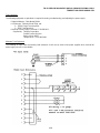
METHOD 2
If system protocol does not allow on-line testing or if transmission facilities to the Test Center are not available, an
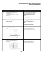
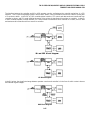
alternative method called back-to-back can be used.
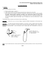
This method requires the use of another functional KD Set (referred to as test set). The test set should be optioned for 8level ASCII code operation at the same baud rate as the set being tested is optioned (Option ZZ). The test set should be
connected as indicated below.
In either arrangement, the clear-to-send input must be turned on (46 V). If no clear-to-send input is available, temporarily
remove the 303181 or 303184 circuit card in slot Z4 of each interface assembly.
2-26
TM 11-5815-606-34/NAVELEX 0969-LP-188-0010/TO 31W4-4-300-1
TEMPEST M40 SHOP MANUAL 359
MANUAL MODE CHECKOUT
The manual mode checkout must be performed with the POLL/SEL lamp not lit and the 5-level communication interface
not selected (no character X in line 1 of control mode) in both the test set and the set under test.
STEP
PROCEDURE
RESULTS
1
Locally prepare a test message on set under test.
Start message with SOH and end message with
ETX.
2
Condition test set to receive (DISP SEND and
POLL/SEL not lit; DISP LINE lamp lit).
3
Home cursor on set under test.
Cursor goes to HOME position.
Depress DISP SEND.
DISP SEND lamp lights.
Depress DISP LINE.
DISP LINE lamp lights.
Message appears on display.
Cursor moves through message and stops at
character position after ETX.
Message is received on display of test set.
NOTE: If Option Z1 (Home on Send) is installed, the cursor will go to home when the DISP LINE key is
depressed. If Option F1 (printer on-line required to send), PTR LINE indicator must be lighted before
sending will start. If Option H1 (monitor tape on required to send) is installed, MONITOR TAPE indicator
must be lit before sending will start.
4
Locally copy test message on display on receive
tape (Cassette 2) of the set under test. (Refer to
How to Operate Manual 405 for procedure.)
Reassign Cassette 2 as the send tape. (Refer to
How to Operate Manual 405 for procedure.)
Position send tape to send test message. Condition
test set to receive.
Depress SEND TAPE LINE.
Send tape sends test message and test set receives
message on display.
2-27
TM 11-5815-606-34/NAVELEX 0969-LP-188-0010/TO 31W4-4-300-1
TEMPEST M40 SHOP MANUAL 359
C. TESTING (Contd)
5.
ON-LINE CHECK-OUT (Contd)
STEP
PROCEDURE
RESULTS
5
On set under test, enter control mode and place
keyboard on-line. Type a character X in line 10 and
depress LINE FEED. Exit control mode. Condition
test set to receive.
Type a test message on keyboard.
Message will be received on test set display.
NOTE: If Option D2 was selected, message will be
copied on set under test display also.
6
Enter control mode. Delete the X in line 10 and
depress the LINE FEED key.
Exit control mode.
7
Locally prepare a test message on test set. Start
message with SOH and end with EOT.
Condition set under test to receive (DISP SEND
lamp not lit; DISP LINE, PTR LINE, and REC TAPE
LINE lamps lit.
Send test message from test set.
Display, printer and receive tape receive message
from test set.
NOTE: Set under test will take received EOT,
transform it into an EXT, display it on display and
record it on receive tape.
8
To check receive tape: Depress CNTRL MODE.
Place an X in line 7 of control message.
Control mode message appears.
Depress LINE FEED.
Receive tape listing will be displayed with first 56
characters of test message.
2-28
TM 11-5815-606-34/NAVELEX 0969-LP-188-0010/TO 31W4-4-300-1
TEMPEST M40 SHOP MANUAL 359
STEP
9
PROCEDURE
RESULTS
Depress the space bar.
The control mode message appears on display.
Delete the X in line 7.
Rewind all tapes and reassign Cassettes 1, 2 and 3
so that Cassette 1 is send tape, Cassette 2 is
receive tape and Cassette 3 is monitor tape. Refer
to How to Operate Manual 405 for procedures.
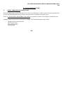
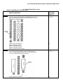
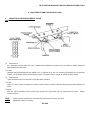
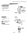
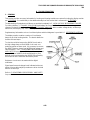
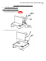
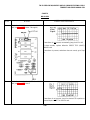
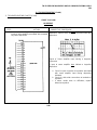
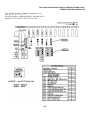
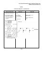
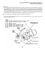
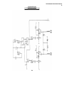
6.
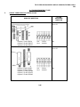
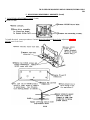
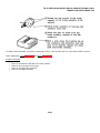
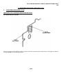
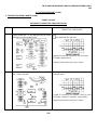
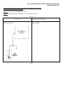
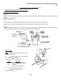
CASSETTE TEST PROGRAM
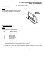
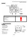
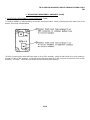
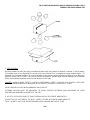
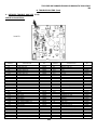
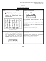
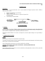
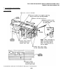
Program Description
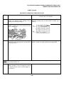
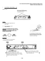
The CP10.006 Cassette Test Program consists of a programmed cassette tape and a modified 410504 circuit card, which
functions to load the program tape into the C400 Controller.
The parts required for this test are as follows:
Parts List
Part No.
Description
CP10.006.004
Programmed Cassette - CD Test Program
for 40C434 Controller
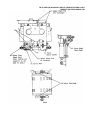
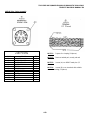
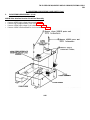
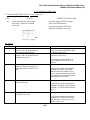
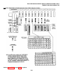
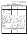
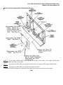
CP10.006.010
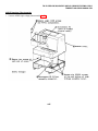
Modified 410504 Circuit Card With Four
Programmed EPROMS Containing Program
Tape Loader Program (See Fig. 1.)
CP10.006.100
EPROM
CP10.006.101
EPROM
TP405403
EPROM
TP451003-1
EPROM
2-29
TM 11-5815-606-34/NAVELEX 0969-LP-188-0010/TO 31W4-4-300-1
359
C. TESTING (Contd)
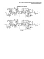
6.
CASSETTE TEST PROGRAM (Contd)
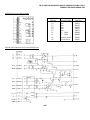
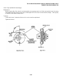
Fig. 1
Parts can be obtained from Teletype Custom Systems Division. See Page 2-4 for ordering information.
This program functions to:
Verify the condition of cassette tapes.
Provide the user with an aid for troubleshooting cassette drives (CD's).
Two parts constitute the program.
Part one is the cassette tape verification stage. Test characters are written from controller memory to the tape
which is to be verified. The tape is then read nine times and compared to controller memory. Word numbers of
errored words will print out during each read cycle. This test will run approximately 25 minutes.
Part two of the test program consists of 38 steps which write and read approximately 10 million characters
to/from the cassette on a block by block basis. Errored blocks will print out and indicate the type of error.
2-30
TM 11-5815-606-34/NAVELEX 0969-LP-188-0010/TO 31W4-4-300-1
TEMPEST M40 SHOP MANUAL 359
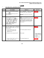
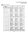
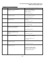
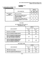
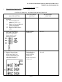
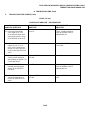
The test program will classify cassette tape errors as "soft" errors. It will rerun the errored blocks-up to nine times. If the
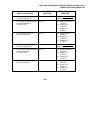
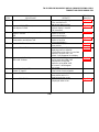
error does not clear, the program will classify it as a "hard" error. Other types of error messages are as follows:
Error Printouts
1.
2.
3.
4.
5.
6.
7.
8.
9.
10.
Cassette not in place
Soft error (cassette error).
Hard error (repeated cassette error)
Positioning error (controller could not find marker)
In write mode not received -- disabled!
Two wrong positions -- off until rewritten!
This tape failed at word #
Drive disabled -- no SS1 or no cassette!
Drive disabled -- too many errors!
Tape fails tape test -- drive disabled!
(Possible response to "REC TAPE LINE" "Y".)
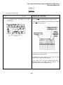
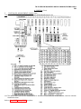
Part two of this program will run for approximately six hours to complete the 38 steps one time, unless otherwise
terminated. This will give the maintenance personnel adequate time to perform cassette drive analysis,
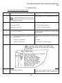
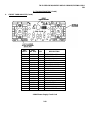
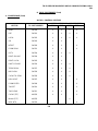
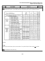
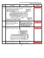
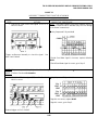
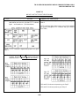
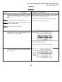
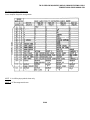
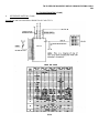
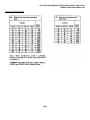
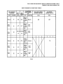
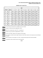
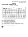
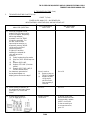
Table 1 lists the specific test program steps. Steps 1A and 1B constitute the tape verification stage. This test is initiated
by depressing the "REC TAPE LINE", '"Y" keys on the operator console.
NOTE: References in this procedure will be to "REC TAPE LINE" key, however, on some units containing a 40K108RDF
keyboard (Terp System), the depressed key will be "NEXT INCOM". In any case, the depressed key should be the eighth
keytop from the left in the top row of keytops.
"REC TAPE LINE" "Z" will execute "REC TAPE LINE" "Y" repeatedly.
Steps 1C through 38 are part two of the test program and function on "REC TAPE LINE" "Q".
Any other commands are not related to this test procedure even if they are functional.
Operating the "DISP LINE" ("LOCAL" for Terp) key after the test has begun, will stop the test and rewind all cassette
tapes.
One to six cassette drives can be accommodated by the program. When multiple drives are used, the drive input port
number will print out with the program responses. This allows service personnel to relate the printout to the drive that
caused it. Sample test copy is included in this procedure for the user's reference.
The user is required to provide one 40C400 Controller for test program use. The controller must be reconfigured and
optioned as follows.
2-31
TM 11-5815-606-34/NAVELEX 0969-LP-188-0010/TO 31W4-4-300-1
359
C. TESTING (Contd)
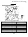
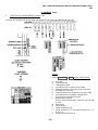
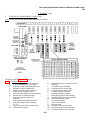
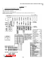
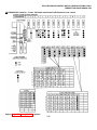
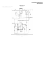
6.
CASSETTE TEST PROGRAM (Contd)
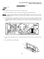
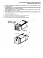
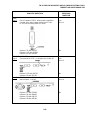
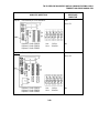
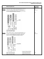
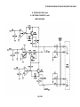
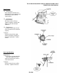
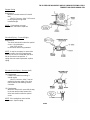
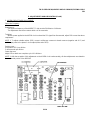
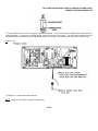
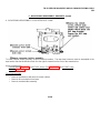
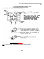
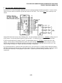
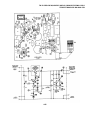
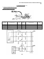
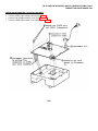
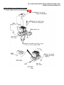
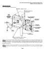
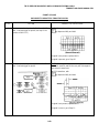
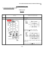
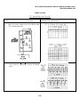
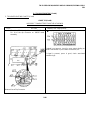
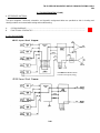
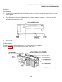
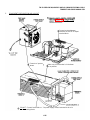
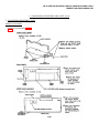
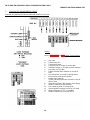
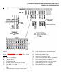
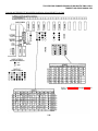
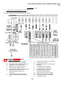
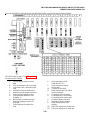
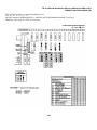
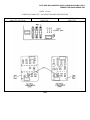
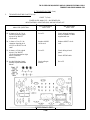
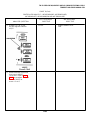
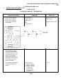
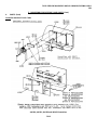
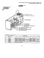
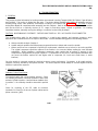
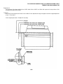
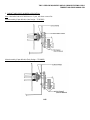
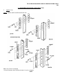
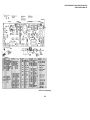
Test Terminal Configuration
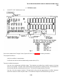
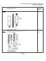
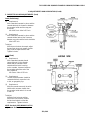
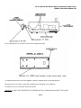
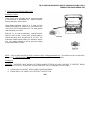
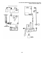
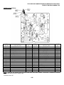
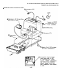
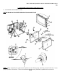
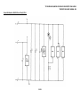
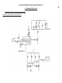
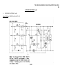
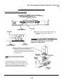
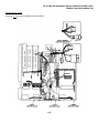
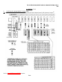
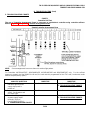
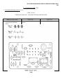
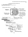
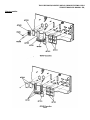
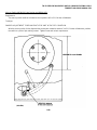
Arrange the controller circuit cards and option them as shown in Fig. 2.
CAUTION: BEFORE HANDLING CIRCUIT CARDS, ATTACH A 346392 STATIC DISCHARGE WRIST STRAP OR
EQUIVALENT. ALSO, ALWAYS TURN CONTROLLER DC POWER OFF BEFORE REMOVING OR INSERTING
CIRCUIT CARDS.
CONTROLLER CONFIGURATION
Arrange Circuit Cards -- Remove Extra Cards
Fig. 2
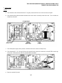
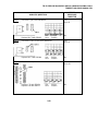
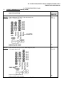
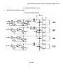
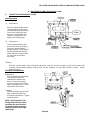
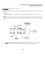
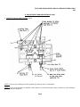
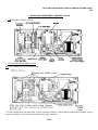
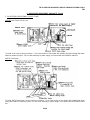
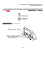
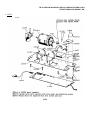
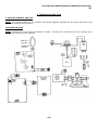
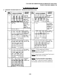
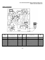
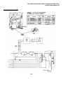
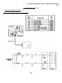
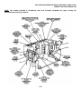
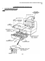
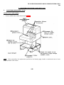
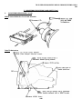
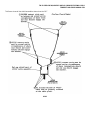
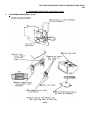
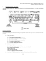
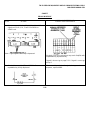
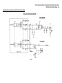
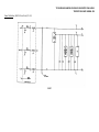
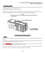
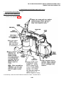
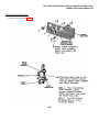
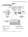
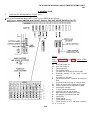
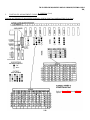
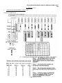
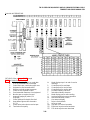
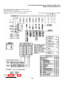
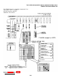
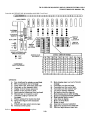
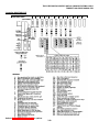
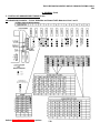
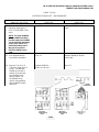
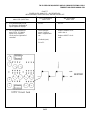
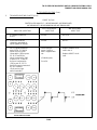
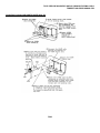
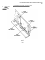
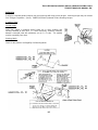
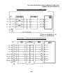
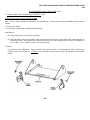
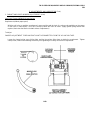
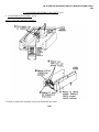
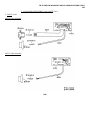
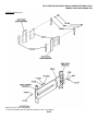
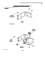
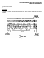
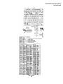
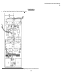
One Model 40 Printer and one operator console (opcon) are required. The printer must be optioned for no error
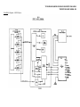
character on parity error. Connect the SSI cables of these units to the controller as shown in Fig. 3.
Two additional cassette drives may be connected to the controller as shown in Fig. 3.
2-32
TM 11-5815-606-34/NAVELEX 0969-LP-188-0010/TO 31W4-4-300-1
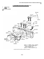
TEMPEST M40 SHOP MANUAL 359
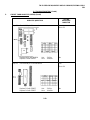
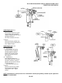
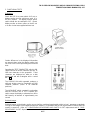
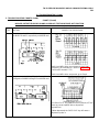
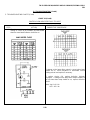
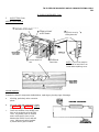
CONTROLLER INPUT-OUTPUT
Fig. 3
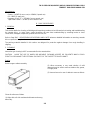
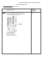
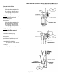
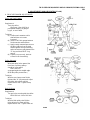
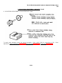
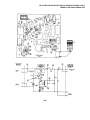
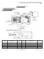
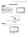
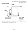
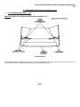
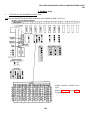
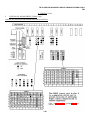
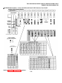
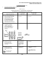
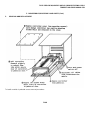
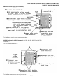
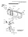
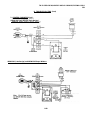
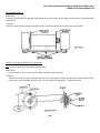
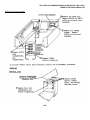
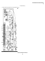
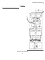
Pretest Precautions
Observe all usual precautions when handling cassette tapes such as never turning off ac power when a cassette is
running.
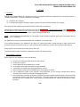
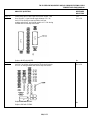
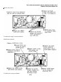
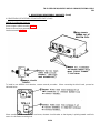
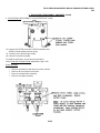
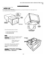
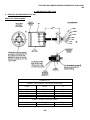
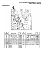
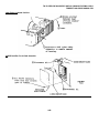
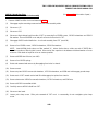
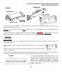
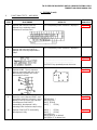
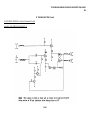
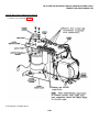
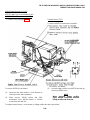
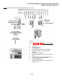
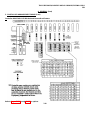
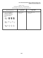
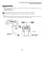
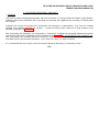
The CP10.006.004 cassette should have been delivered in the write protect (write inhibit) mode. Be sure the write
protect tab is up and to the right before using. Refer to Fig. 4.
2-33
TM 11-5815-606-34/NAVELEX 0969-LP-188-0010/TO 31W4-4-300-1
359
C. TESTING (Contd)
6.
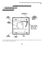
CASSETTE TEST PROGRAM (Contd)
NOTE: Write inhibit tab of CP10.006.004 cassette program tape must ALWAYS be to the right (window uncovered) to
prevent destruction of program.
Fig. 4
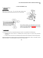
Clean all cassette drive heads before and after testing. Check the 403238 tape cleaner and replace if required.
Double check test terminal cable connections, Fig. 3, and controller card arrangement and options according to Fig. 2.
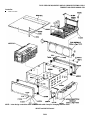
Program Loading
Remove all cassette tapes, if any, from all cassette drives.
Turn on ac power to the test terminal.
Power On Reset (POR) the 40C400 controller by operating its power supply switch to the OFF and then ON position.
Be sure the CP10.006 program cassette is write inhibited. Insert the program tape into any one of the cassette drives
which is known to be in good working order. Push the cassette forward to start in the normal manner. The test program
will load into the controller memory.
The monitor cursor will appear and the "DT.SP LINE" ("LOCAL" for Terp) lamp will light if the program has loaded
properly.
If the program did not load properly, repeat the load procedure by power on resetting the power supply.
2-34
TM 11-5815-606-34/NAVELEX 0969-LP-188-0010/TO 31W4-4-300-1
TEMPEST M40 SHOP MANUAL 359
When the cassette drive RUN/TEST lamp has gone off, remove the program tape from the drive and store away. Never
remove a cassette when the lamp is on.
Load the desired number of drives with cassette tapes to be checked. All tapes will go thru the normal self test upon
loading. A flashing RUN/TEST lamp indicates that the self-test has failed.
New cassettes may not be added after testing has begun. However, any drive may be removed from test at any time by
disconnecting its SSI cable from the controller.
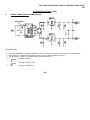
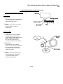
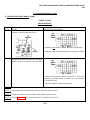
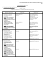
Program Execution
Tape verification. Operator console should now have "DISP LINE" (or "LOCAL") lighted.
Home the cursor (HOME position is fourth line down). Now Clear.
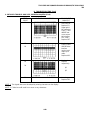
Depress "REC TAPE LINE" "Y" on the opcon. See below for sample copy for explanation of this command.
Cassette Drive 38 Step Exercise
Depress "DISP LINE" (or "LOCAL). Home the cursor and clear the monitor.
Depress "REC TAPE LINE" "Q". Refer to Page 2-36 for explanation of this command and see the sample copy.
Depressing the "DISP LINE" (or "LOCAL") key during the test will stop the test and cause all cassettes to rewind.
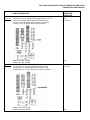
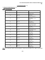
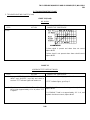
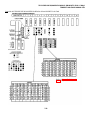
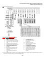
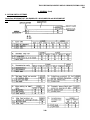
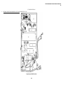
Printout from "REC TAPE LINE." "Y". Only the port number column has meaning at the right hand side last four
columns. The first column will indicate the number of times "REC TAPE LINE" "Y" has been repeated if "REC TAPE
LINE" "Z" has been used to do "Y" repeatedly.
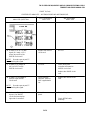
Response to "REC TAPE LINE" "Y"
Monitor will display "40 CD TEST PROGRAM".
If tape has no errors, no other printout will occur.
Monitor will display "TEST COMPLETE" after end of test.
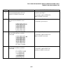
4φCD TEST PROGRAM
THIS TAPE FAILED AT WORD
THIS TAPE FAILED AT WORD
THIS TAPE FAILED AT WORD
THIS TAPE FAILED AT WORD
THIS TAPE FAILED AT WORD
THIS TAPE FAILED AT WORD
THIS TAPE FAILED AT WORD
THIS TAPE FAILED AI WORD
THIS TAPE FAILED AT WORD
TEST COMPLETE
≠φφφ,411
≠φφφ,411
≠φφ1,195
≠φφ1,195
≠φφφ,914
≠φφφ,914
≠φφ1,195
≠φφφ,914
≠φφφ,914
φ1
φ1
φ1
φ1
φ1
φ1
φ1
φ1
φ1
5
5
5
5
5
5
5
5
5
φ1
φ1
φ1
φ1
φ1
φ1
φ1
φ1
φ1
Printout using "REC TAPE LINE" "Q" when there are no cassettes in any of the cassette drives. This sample is included
to illustrate the meaning of the columns at the right-hand side of the page. The two digits at the extreme right will
indicate the program step in process during the execution of "REC TAPE LINE" "Q".
2-35
TM 11-5815-606-34/NAVELEX 0969-LP-188-0010/TO 31W4-4-300-l1
359
C. TESTING (Contd)
6.
CASSETTE TEST PROGRAM (Contd)
Program Execution (Contd)
The next column to the left is the input port number of the cassette SSI cable to: the C400 controller; Port 6 will
correspond to controller SSI connector J310, Port 5 will correspond to connector J308 etc. The next two three digit
numbers to the left are the block number and the last column to the left has no significance to this procedure.
Printout from "REC TAPE LINE" "Q". This sample shows the entire 38 steps of the program using a good cassette tape
being read from the cassette drive which is connected to Port 5 (J308). Note that the printout indicates that Ports 1, 2, 3,
4, and 6 are either not being used or have defective drives and/or cassette tapes. Also note that the cassette tape ran
error free until block 461 during Step No. 36. At this time an error was detected; when the controller reread the tape the
fifth time, the error had cleared and the program continued.
2-36
TM 11-5815-606-34/NAVELEX 0969-LP-188-0010/TO 31W4-4-300-1
TEMPEST M40 SHOP MANUAL 359
2-37
TM 11-5815-606-34/NAVELEX 0969-LP-188-0010/TO 31W4-4-300-1
359
C. TESTING (Contd)
6.
CASSETTE TEST PROGRAM (Contd)
CHART
STEP
PROCEDURE
Step 1A
The ASCII characters "+" and "3" are written onto the tape continuously over an area equivalent to
approximately 520 blocks.
Step 1B
The tape is then read and each character received by the C400 is compared bit by bit to "+" and "3".
Step 1C
The ASCII characters "+" and "3" are written onto Channel 1 and the ASCII characters "T" and "L" are
written onto Channel 2. There will be 129 SSI words containing +3 on Channel 1 and 129 SSI words
containing TL on Channel 2. In addition, there will be two more SSI words on Channel 1, a word
containing (New Line-ETX) and a block check word. Also, Channel 2 will contain one more SSI word
(Block No.). The above block of 261 SSI words or 522 characters is written onto the tape with "markers".
A total of 500 blocks are written (0 to 499).
Step
2
through Step
10
Read one block at a time.
Step 11
The same as Step 1C except TL is written onto Channel 1 and +3 is written onto Channel 2. The blocks
are written without "markers".
Step 12
Read block 490 and then read block 10.
Step
13
through Step
21
Read one block at a time.
Step 22
The same as Step 1C.
Step 23
The same as Step 12.
Step
24
through Step
32
Read one block at a time.
Step 33
Write with "markers" (TL on Channel 1 and +3 on Channel 2) followed by a "REW" and then a READ.
This test is performed one block at a time.
Step 34
Write without "markers" (+3 on Channel 1 and TL on Channel 2) followed by a "REW" and then a READ.
This test is performed one block at a time.
2-38
TM 11-5815-606-34/NAVELEX 0969-LP-188-0010/TO 31W4-4-300-1
TEMPEST M40 SHOP MANUAL 359
CHART (Contd)
STEP
PROCEDURE
Step 35
Same-as Step 12.
Step 36
Same as Step 33.
Step 37
Same as Step 34.
Step 38
Read Block 0, 50, 100, 150, 200, 250, 300, 350, 400, 450, 490, 451, 401, 351, 301, 251, 201, 151, 101,
51 and 10.
The following procedure is used to check the outputs of the magnetic tape head assembly. The controller should be
configured as it was for use with the Cassette Test Program. See Fig. 2, Page 2-32 for configuration. After execution of
this procedure, the controller should be configured in it's original state. The tape head checkout procedure utilizes a
special cassette tape No. 10.006.020 which is available from Teletype Custom Systems Division. See Page '2-4 for
ordering information. The 410764 circuit card contained in the cassette drive unit must be electrically extended from the
base to provide access to the components. Refer to D. TROUBLESHOOTING, Page 2-40 for further information.
Observe all usual precautions when handling cassette tapes such as never turning off ac power when a cassette is
running.
The CP10.006.020 Cassette Tape should have been delivered in the write protect (write inhibit) mode. Be sure the write
protect tab is up and to the right before using.
Turn on ac power to the test terminal.
Power On Reset (POR) the 40C400 controller by operating its power supply switch to the OFF and then ON position.
Be sure the CP10.006.020 Program Cassette is write inhibited. Insert the program tape into the cassette drive. Push the
cassette forward to start in the normal manner. The tape should be allowed to run to the end and the check should be
made only with the tape moving in the forward direction.
If the program did not load properly, repeat the load procedure by power on resetting the power supply. The power
supply should also be reset before each new check.
2-39
TM 11-5815-606-34/NAVELEX 0969-LP-188-0010/TO 31W4-4-300-1
359
C. TESTING (Contd)
6.
CASSETTE TEST PROGRAM (Contd)
With tape moving in the forward direction, check anode of CR16 (with Channel 1 of scope), and anode of CR17 (with
Channel 2 of scope) for waveform shown in Fig. 5. The two waveforms must be in phase within +10 microseconds. If
waveforms do not meet requirement, replace the 403241 tape head assembly. Refer to F. DISASSEMBLY/
REASSEMBLY AND PARTS for replacement procedure.
Fig. 5
D. TROUBLESHOOTING
1.
GENERAL
This section provides troubleshooting methods to be followed in repairing the Tempest Model 40 Cassette Drive Units.
When trouble is encountered in testing a cassette drive, the diagnostic steps and corrective measures should be followed
to arrive at the trouble source. After corrective steps have been verified by successfully repeating the test that disclosed
the problem, the testing procedure should be resumed.
Functional schematics have been supplied in 6.
troubleshooting.
FUNCTIONAL SCHEMATICS of this section as an aid to
Waveshapes and voltage levels specified for troubleshooting the cassette drive logic circuit card are to be checked with
an oscilloscope unless stated otherwise.
Continuity and dc voltage checks specified for troubleshooting are to be made with a multimeter.
2-40
TM 11-5815-606-34/NAVELEX 0969-LP-188-0010/TO 31W4-4-300-1
TEMPEST M40 SHOP MANUAL 359
If the cassette drive fails to perform its intended function, the difficulty should be analyzed in a logical manner to
recognize the source of the problem. Above all, make certain it is the cassette drive which is causing the problem rather
than associated apparatus or electronics.
Take the time to pinpoint the exact nature of the difficulty rather than just a general description. For example, it would be
of much more use to be able to say that "The brake fails to operate properly" rather than "The unit is failing to transmit
data properly".
Check to see that all springs are attached and parts mounted properly. No adjustment should be changed
indiscriminately in an effort to correct a difficulty which is not fully understood. Very often this will only result in more
than one difficulty being present.
As an aid to troubleshooting, the following list of troubles and remedies are intended to serve as a guide in the analysis
and correction of difficulties. The associated schematic wiring diagrams of this specification are required for reference.
These remedies are intended for field repair and, as such, will call for the most expeditious solution to the problem. For
instance, if a clutch fails, the immediate solution would be to replace it.
2-41
TM 11-5815-606-34/NAVELEX 0969-LP-188-0010/TO 31W4-4-300-1
TEMPEST M40 SHOP MANUAL 359
D. TROUBLESHOOTING (Contd)
1.
General (Contd)
SYMPTOM
POSSIBLE CAUSE
REMEDY
Cassette drive motor does not turn on.
1. Loss of ac power.
Check all fuses and switches between 40CD101 and ac
source.
Motor runs, but nothing else operates, selftest is not performed.
1. Interface circuit open.
Make sure interface circuit is complete.
2. No dc power.
Check power source and replace faulty portion.
3. Cassette in place or file protect switch are
inoperative.
Readjust switches per E. ADJUSTMENTS AND
LUBRICATION.
Either brake or clutch fail to operate.
1. Open coil.
Replace complete set of faulty items.
Either clutch fails to operate properly.
1. Dirty clutch armature rotor faces.
Clean faces.
2. Improper clutch adjustment,
Readjust clutch per E. ADJUSTMENTS AND
LUBRICATION.
1. Dirty armature face.
Clean armature face.
2. Improper brake adjustment.
Readjust per E. ADJUSTMENTS AND LUBRICATION.
1. Dirty head or tape.
Clean the tape head.
2. Damaged tape, ie, wrinkled tape or oxide layer is
scratched.
Use new tape cassette.
3. Dirty tape cleaner.
Replace cleaner.
4. Faulty belt adjustments.
Readjust "O Ring" belt and flat belt per E.
ADJUSTMENTS AND LUBRICATION.
Either brake fails to operate properly
(usually evidenced by slack in the tape).
Garbling of data in read or write mode.
2-42
TM 11-5815-606-34/NAVELEX 0969-LP-188-0010/TO 31W4-4-300-1
TEMPEST M40 SHOP MANUAL 359
SYMPTOM
POSSIBLE CAUSE
REMEDY
Cleaning bobbin fails to rotate
1. Faulty adjustment.
Readjust bobbin per E. ADJUSTMENTS
AND LUBRICATION.
2. Weak flat spring.
Bend spring per E. ADJUSTMENTS AND
LUBRICATION.
3. Weak tension spring.
Replace spring.
2-43
TM 11-5815-606-34/NAVELEX 0969-LP-188-0010/TO 31W4-4-300-1
TEMPEST M40 SHOP MANUAL 359
D. TROUBLESHOOTING (Contd)
2.
ERROR ANALYSIS
Table A is provided as a guide for associating errors with likely causes and recommends specific areas of the cassette
drive to be checked.
TABLE A
Errors Caused By Acceleration Problem:
1.
2.
3.
4.
5.
6.
Generally occur in first third of block.
Can result in incomplete block error with more than one missing SSI word.
Will usually cause errors on both channels.
Errors will usually change with each reread.
Will not cause character errors with just one or two bits incorrect.
If written with acceleration problem, data cannot be recovered correctly no matter how many rereads are
attempted.
Errors Caused By Tape:
1. Can occur anywhere in block.
2. Can occur on one or both channels.
3. Damaged tape will usually cause incomplete block errors. (Even if rewritten, block cannot be recovered
correctly.)
4. Debris on tape will usually cause one character error which could be distributed throughout the block.
5. Blocks written with debris on tape cannot be recovered correctly no matter how many rereads are made
even if debris falls off of tape.
Errors Caused By Tape Head:
1. If head has debris on it, incomplete block errors will result. (Lost data could be from one or both channels).
2. If skew adjustment is out, data errors will result throughout block.
3. If mechanical dimensions are out, data errors and incomplete blocks will result.
Errors Caused By Circuit Card:
1. Generally circuit card errors will result in many or all blocks being either written or read incorrectly.
Types of errors and the manner in which they manifest themselves are listed in Table B. The following procedures are
recommended for testing and analyzing test results.
The drive in question should be allowed to complete enough steps of the test program to allow sufficient data for
analysis.
2-44
TM 11-5815-606-34/NAVELEX 0969-LP-188-0010/TO 31W4-4-300-1
TEMPEST M40 SHOP MANUAL 359
The first step of error analysis is to remove the tape from the drive in question and verify the tape in a known good drive.
If the tape does not verify properly, it should be discarded and another-properly conditioned tape installed in the drive in
question. The drive in question should be watched closely because it may be damaging tapes. If the tape verifies
properly, the drive in question should be examined.
If errors occur on both channels and near the beginning of the block, acceleration is most likely the cause of the errors.
Check the items listed under ACCELERATION ERRORS, and also check the items listed under IRREGULAR DATA
PATTERN.
If the errors occur only on one channel, the items listed under HEAD RELATED ERRORS may apply. If these items are
suspected, replace the 410764 circuit card with a known good card.
If the errors occur anywhere throughout a block and on both channels, check the items listed under ACCELERATION
ERRORS and IRREGULAR DATA PATTERN. If these items are okay, replace the 410764 circuit card with a known
good card.
If the errors are positioning type errors, check the items listed under COAST PROBLEMS and CLUTCH PICKUP
PROBLEMS.
If a cassette drive will not verify a cassette tape, check the items listed under MOTION PROBLEMS.
TABLE B
ACCELERATION ERRORS
1.
2.
3.
4.
5.
6.
7.
8.
Check connections at Berg connector (brakes and clutches).
Check brake gap adjustment (forward and reverse).
Check holdback torque with tension monitor.
Check belt tension.
Check clutch torque.
Check yield spring tension.
Check end play and side to side play of all shafts.
Check brake disc and armature (both forward and reverse).
IRREGULAR DATA PATTERN
1.
2.
3.
4.
5.
Check end play and side to side play of all shafts.
Check clutch torque.
Check belt tension.
Check yield spring tension.
Check brake disc and armature.
HEAD RELATED ERRORS
1.
2.
3.
4.
Channel amplitude incorrect.
Skew (read head outputs out of phase).
Flutter (one channel jittering with respect to other).
Check for wear.
2-45
TM 11-5815-606-34/NAVELEX 0969-LP-188-0010/TO 31W4-4-300-1
359
D. TROUBLESHOOTING (Contd)
2.
ERROR ANALYSIS (Contd)
TABLE B (Contd)
COAST PROBLEMS
1.
2.
3.
4.
5.
Check connections at Berg connector.
Clean clutches and brake disc.
Check polarity of clutches and brakes.
Check brake and clutch gaps.
Check resistance of brake coils.
CLUTCH PICKUP PROBLEMS
1.
2.
3.
4.
Check connections at Berg connector.
Clean clutches and brake disc.
Check brake and clutch gaps.
Check resistance of clutch coils.
MOTION PROBLEMS
1.
2.
3.
4.
5.
Check end play and side to side play of all shafts.
Check clutch torque.
Clean clutches.
Check belt tension.
Check head.
Refer to Section E. ADJUSTMENTS AND LUBRICATION for adjustment procedures.
2-46
TM 11-5815-606-34/NAVELEX 0969-LP-188-0010/TO 31W4-4-300-1
TEMPEST M40 SHOP MANUAL 359
3.
COMPONENT ANALYSIS
NOTE: In the following sections, where references are made to specific adjustments and/or lubrications, refer to E.
ADJUSTMENTS AND LUBRICATION for procedures. Perform repair steps listed in the “NO” RESPONSE DIRECTIVE
column in the order specified until trouble is corrected.
ANALYSIS QUESTION
“YES” RESPONSE
DIRECTIVE
“NO” RESPONSE
DIRECTIVE
1.
With the Cassette Drive
power switch in the "ON"
position, does motor run?
Go to 4.
Go to 2.
2.
Is 115 volts available at
source?
Go to 3.
Repair or replace
voltage.
3.
With motor connector
removed from ac distribution
assembly connector, is 115
volts present at ac distribution
assembly connector?
(a) Disconnect power
supply from motor
connector and
replace motor.
(b) Replace connector
(a) Replace 408598
SSI/AC interface
assembly.
(b) Replace connector.
4.
With no cassette in the
cassette holder and power
switch in the "ON" position, is the BOT/EOT lamp
lit?
Go to 9.
Go to 5.
5.
Is power supply fuse "open"?
Check continuity.
continues to "blow".
Recheck power- supply.
Replace fuse, recheck.
Recheck if fuse
Go to 6.
6.
Is -12 volts present at
power supply? Check for
-12 volts dc between terminals
marked common and -12.
Go to 5. CIRCUIT
CARD ANALYSIS.
(410764)
Go to 7.
7.
Is transformer output
voltage present (approximately
31.6 volts ac) present between
unmarked terminals on power
supply circuit card?
(a) Go to 4. CIRCUIT
CARD ANALYSIS.
(410043)
(b) Replace 406101
power supply.
Go to 8.
2-47
TM 11-5815-606-34/NAVELEX 0969-LP-188-0010/TO 31W4-4-300-1
359
D. TROUBLESHOOTING (Contd)
3.
COMPONENT ANALYSIS (Contd)
ANALYSIS QUESTION
“YES” RESPONSE
DIRECTIVE
“NO” RESPONSE
DIRECTIVE
8.
Is transformer input voltage
present (103 to 127 volts ac)
between pins 1 and 3 of
connector P8?
Replace 406103
transformer.
Replace 408598 SSI/
AC interface
assembly
9.
Is RUN (Status ) lamp lit?
Go to 5. CIRCUIT
CARD ANALYSIS
(410764)
Go to 10.
10.
Does RUN (Status) lamp light
when the “Cassette in Place”
switch is manually activated?
Go to 13.
Go to 11.
11.
Is +12 volts dc present at
power supply? Check for +12
volts dc between terminals
marked common and +12.
Go to 12.
(a) Go to 4. CIRCUIT
CARD ANALYSIS.
(410043)
(b) Replace power
supply 406101.
12.
With power removed from the
cassette drive, the cassette
drive removed from its base,
and plug P4 removed from the
J4 connector, is there
continuity between terminals
2 and 9 of plug P4?
Go to 5. CIRCUIT
CARD ANALYSIS
(410764)
(a) Go to 5. CIRCUIT
CARD ANALYSIS.
(410764)
(b) Replace 406111
cassette in
place switch.
(c) Perform switch
height adjustment.
13.
Does left drive shaft
(rewind) hub rotate when
“Cassette in Place”switch
is manually activated?
Go to 18.
Go to 14.
14.
Does left drive shaft
(rewind) rotor rotate?
Go to 15.
Go to 18.
15.
Is clutch activated when
the “Cassette in Place”
switch is actuated?
Perform pulley and
shaft end play
adjustment.
Go to 16.
16.
Is clutch out of adjustment?
Adjust clutch.
Go to 17.
2-48
TM 11-5815-606-34/NAVELEX 0969-LP-188-0010/TO 31W4-4-300-1
TEMPEST M40 SHOP MANUAL 359
D. TROUBLESHOOTING (Contd)
3.
COMPONENT ANALYSIS (Contd)
ANALYSIS QUESTION
“YES” RESPONSE
DIRECTIVE
“NO” RESPONSE
DIRECTIVE
17.
With power removed from
cassette drive, drive removed
from base and the P4B
connector removed from J4
connector is resistance
between terminals 3 and 8
of P4B 32 to 50 ohms?
Go to 5. CIRCUIT
CARD ANALYSIS
(410764)
(a) Replace 402271
clutch assembly.
(b) Perform clutch
adjustment.
(c) Perform pulley
alignment adjustment.
18.
Does right drive shaft
(forward drive) rotor
rotate?
Go to 19.
Go to 23.
19.
Is O-Ring belt present?
Go to 20.
Assemble O-Ring belt.
20.
Are left drive shaft
(rewind) pulley and idler
pulley present?
Go to 21.
Assemble missing
pulley/pulleys.
21.
Are left drive shaft
(rewind) Pulley set screws
(2) tight?
Go to 22.
Tighten set screws.
22.
Does left drive shaft
(rewind) pulley bind on
casting?
Adjust for end play.
(a) Replace 403296
brake assembly.
(b) Perform brake
adjustment.
(c) Perform pulley
and shaft end
play adjustment.
(d) Perform latch
adjustments.
23.
Is motor drive belt present?.
Go to 24.
Assemble Belt.
24.
Are right drive shaft (forward
drive) pulley set screws tight?
Go to 25.
Tighten set screws.
25.
Are motor pulley set screws
tight?
Go to 26.
Tighten set screws.
26.
Does right drive shaft (forward
drive) pulley bind on casting?
Adjust for end play.
(a) Perform motor drive
belt adjustment.
(b) Perform motor
pulley adjustments.
(c) Replace 403296
brake assembly.
(d) Perform brake
adjustment.
2-49
TM 11-5815-606-34/NAVELEX 0969-LP-188-0010/TO 31W4-4-300-1
TEMPEST M40 SHOP MANUAL 359
D. TROUBLESHOOTING (Contd)
3.
COMPONENT ANALYSIS (Contd)
ANALYSIS QUESTION
“YES” RESPONSE
DIRECTIVE
26.
“NO” RESPONSE
DIRECTIVE
(e) Perform pulley
and shaft end
play adjustment.
(f) Perform latch
adjustments.
(g) Go to 5. CIRCUIT
CARD ANALYSIS.
(410764)
(Contd)
27.
With a partially unwound
standard cassette placed
wrong side out, is the
cassette held flat against
inside surface of the
cassette holder?
Go to 28.
Adjust cassette
pressure spring.
28.
Is cassette holder properly
latched?
Go to 29.
Adjust latch.
29.
Does the left drive (rewind)
shaft rotate?
Adjust "Cassette in
Place Switch".
Go to 30.
30.
When removing cassette
does latch open too far?
Adjust latch stop
screw.
Go to 31.
31.
Is cassette holder ejected
from drive mechanism?
Go to 32.
Adjust cassette
holder pressure
spring.
32.
With the cassette properly
assembled to the cassette
holder, did the cassette
rewind?
Go to 34.
Go to 33.
33.
With the cassette removed
from the cassette holder, do
both reels rotate freely?
Adjust "Cassette in
Place" switch height.
Replace cassette.
34.
After rewinding, does the
tape move forward and rewind?
Go to 36.
(a) Cassette drive
not plugged into
mating equipment.
(b) Go to 35.
35.
With power switch in the OFF
position, remove system cable
from mating equipment
connector and connect it to a
known good part. Restore
power to cassette drive, does
tape move forward and rewind?
Replace or repair
mating equipment.
Restore Cassette Drive.
to proper configuration.
(a) Replace system
cable.
(b) Replace 408598
SSI/AC interface
assembly.
(c) Go to 5. CIRCUIT
CARD ANALYSIS.
(410764)
2-50
TM 11-5815-606-34/NAVELEX 0969-LP-188-0010/TO 31W4-4-300-1
TEMPEST M40 SHOP MANUAL 359
D. TROUBLESHOOTING (Contd)
3.
COMPONENT ANALYSIS (Contd)
ANALYSIS QUESTION
“YES” RESPONSE
DIRECTIVE
“NO” RESPONSE
DIRECTIVE
36.
Does tape move forward
and reverse a second time?
Go to 38.
Go to 37.
37.
Does cassette have red tab
on left side folded back
so that notch is exposed?
Go to 38.
(a) Adjust "Write
Inhibit Switch".
38.
Does the RUN (Status) lamp
turn off or flash when
tape is rewound?
Go to 41.
Go to 39.
39.
Is the tape between the
BOT/EOT sensor tube
mechanism transparent?
Go to 40.
(a) Replace cassette.
(b) Go to 5. CIRCUIT
CARD ANALYSIS.
(410764)
(c) Replace 406123
cable assembly.
(d) Perform sensor
tube adjustment.
40.
Is the hole in the underside of the sensor tube
over the BOT/EOT lamp?
Go to 5. CIRCUIT
CARD ANALYSIS.
(410764)
Perform sensor
tube adjustment.
41.
Does the RUN (Status)
lamp flash?
Go to 42.
Go to 43.
42.
Remove cassette and place
in known good Cassette Drive.
Does RUN (Status) lamp flash
after moving forward and
reversing when "Write Inhibit"
tab is folded back (see
Step 37) or after moving
forward, reversing, moving
forward again and reversing
a second time for "Write
Inhibit" tab not folded back?
Cassette bad - replace.
Go to 45.
43.
With the cassette drive
connected to a M40 KD or
KDP capable of receiving
from a cassette drive and
using a cassette previously
recorded on the cassette
drive, can text be sent to
the display?
Go to 44.
Go to 48.
44.
Is text garbled?
Go to 45.
Cassette drive good.
2-51
TM 11-5815-606-34/NAVELEX 0969-LP-188-0010/TO 31W4-4-300-1
TEMPEST M40 SHOP MANUAL 359
D. TROUBLESHOOTING (Contd)
3.
COMPONENT ANALYSIS (Contd)
ANALYSIS QUESTION
“YES” RESPONSE
DIRECTIVE
“NO” RESPONSE
DIRECTIVE
45.
Replace the cassette used
in Step 43 with a known
properly recorded cassette
- does garbling still occur?
Go to 46.
Go to 5. CIRCUIT
CARD ANALYSIS.
(410764)
46.
Is the tape cleaner bobbin
indexed as the cassette is
inserted and removed?
Go to 47.
(a) Adjust bobbin
latch spring.
(b) Check bobbin
ratchet spring
requirement.
(c) Check bobbin
stepper spring
requirement.
(d) Replace tape
cleaner bobbin.
47.
Is "O" Ring Belt frayed?
Replace "O" Ring
Belt 403289.
48.
Is tape cleaner bobbin dirty?
Replace 403238 tape
cleaner bobbin.
(a) Check Drive Belt
adjustment.
(b) Check "O" Ring
Belt adjustment.
(c) Clean recording
head.
(d) Clean clutch faces.
(e) Clean brake faces.
(f) Adjust clutches.
(g) Adjust brakes.
(h) Go to 5. CIRCUIT
CARD ANALYSIS.
(410764)
49.
Does associated display
indicate Block Number
or 000?
Cassette drive good
- mating equipment
at fault.
(a) Replace System
Cable.
(b) Replace 408598
SSI/AC interface
assembly.
(c) Go to 5. CIRCUIT
CARD ANALYSIS.
(410764)
2-52
Go to 48.
TM 11-5815-606-34/NAVELEX 0969-LP-188-0010/TO 31W4-4-300-1
TEMPEST M40 SHOP MANUAL 359
4.
CIRCUIT CARD ANALYSIS (410043)
If the repair troubleshooting instructions do not serve to correct the defective card, refer to functional schematics in this
section for further analysis.
View of circuit card connection looking from the top of all components. These designations are for reference only.
DIODE
E = emitter
C = collector
B = base
Pin callouts for different size circuit packs.
Miscellaneous component identification callouts.
2-53
TM 11-5815-606-34/NAVELEX 0969-LP-188-0010/TO 31W4-4-300-1
359
D. TROUBLESHOOTING (Contd)
4.
CIRCUIT CARD ANALYSIS (Contd)
REF.
DESIG.
PART
NO. REQ.
QTY
QR1
QR2
402201
402204
1
1
REGULATOR, +12V
REGULATOR, -12V
R1, R2
171580
2
RESISTOR 470, IW
C3, C4
C5
305455
321158
2
1
CAPACITOR, 15 MFD
CAPACITOR, 0.1 MFD
CR1-4
312341
4
DIODE, IN4004
AL-A5
137471
5
POST
407348
111017
107116
3606
2
4
4
4
HEAT SINK
SCREW, 6-40 X .312 PAN
WASHER, STAR
NUT, 6-40 HEX.
409043
1
BOARD, CIRCUIT
DESCRIPTION
410043 Power Supply Circuit Card
2-54
TM 11-5815-606-34/NAVELEX 0969-LP-188-0010/TO 31W4-4-300-1
TEMPEST M40 SHOP MANUAL 359
ANALYSIS QUESTION
“YES” RESPONSE
DIRECTIVE
“NO” RESPONSE
DIRECTIVE
1.
Is 15.8 volts ac (RMS) present
at terminal marked A3?
Go to 2.
Go to 3. COMPONENT
ANALYSIS.
2.
Is +18 volts dc (approximately)
present at cathodes of
CR1 and CR2?
Go to 3.
(a) Replace CR1-CR2.
(312341)
(b) Replace CS.
(321158)
(c) Replace C1.
(336027)
3.
Is +12 volts dc present at
terminal marked A1?
Go to 4.
(a) Replace QR1.
(402201)
(b) Replace C3.
(305455)
(c) Replace R1.
(171580)
4.
Is 15.8 volts ac (RMS) present
at terminal marked A4?
Go to 5.
Go to 3. COMPONENT
ANALYSIS.
5.
Is -18 volts dc (approximately)
present at anodes of
CR3 and CR4?
Go to 6.
(a) Replace CR3-CR4.
(312341)
(b) Replace C5.
(321158)
(c) Replace C2.
(336027)
6.
Is -12 volts dc present at
terminal marked A5?
410043 card is good.
(a) Replace QR2.
(402204)
(b) Replace C4.
(305455)
(c) Replace R2.
(171580)
2-55
TM 11-5815-606-34/NAVELEX 0969-LP-188-0010/TO 31W4-4-300-1
359
D. TROUBLESHOOTING (Contd)
4.
CIRCUIT CARD ANALYSIS (410043) (Contd)
Information Notes:
1. Terminal designations enclosed in parenthesis are for reference only and are not marked on the components.
2. All resistors are ¼ watt and all resistance values in ohms, unless otherwise specified.
3. All capacitance values in microfarads unless otherwise specified.
4.
Indicates Common.
Indicates Frame Ground.
5. SL-BL
Indicates Slow Blowing.
2-56
TM 11-5815-606-34/NAVELEX 0969-LP-188-0010/TO 31W4-4-300-1
TEMPEST M40 SHOP MANUAL 359
5.
CIRCUIT CARD ANALYSIS (410764)
General
CAUTION 1: TO AVOID POSSIBLE INTERNAL DAMAGE TO THE MOS DEVICES, OR CARD WITH MOS DEVICES,
DUE TO ELECTRICAL STATIC DISCHARGE BY SERVICE PERSONNEL, THE DETAILED PROCEDURES LISTED
SHOULD BE FOLLOWED.
(a)
(b)
(c)
(d)
(e)
ALL MOS DEVICES SHOULD BE DELIVERED AND STORED IN CONDUCTIVE CARRIERS SUCH AS
FOAM PADS OR ALUMINUM TUBES.
ALL HANDLING OF MOS DEVICES, OR CARDS WITH MOS-DEVICES, SHOULD BE DONE AT A
GROUNDED BENCH WITH A CONDUCTIVE FOAM PAD OR AT A LOCATION WHERE THE SERVICE
PERSONNEL CAN BE MAINTAINED AT GROUND POTENTIAL.
ALL PERSONNEL HANDLING MOS DEVICES, OR CARDS WITH MOS DEVICES, MUST WEAR A STATIC
PROTECTION GROUNDING STRAP ADJUSTED TO MAKE FILM CONTACT WITH THE SKIN AT ALL
TIMES.
MOS DEVICES DELIVERED IN ALUMINUM TUBES OR FOAM PADS MAY BE TRANSFERRED TO WORK
AREA PAD BY TOUCHING CARRIER OR PAD FIRST, AND REMOVING DEVICES BY THEIR PACKAGE
(BODY), RATHER THAN BY THE LEADS, IF AT ALL POSSIBLE. HOWEVER, THESE DEVICES SHALL
ALWAYS BE POSITIONED SO THAT THE LEGS ARE IN CONTACT WITH THE FOAM AT ALL TIMES.
SOLDERING IRONS, TEST, AND INSERTION EQUIPMENT MUST BE GROUNDED.
Service personnel are never to be connected directly to ground, but rather through a high resistance discharge path of a
minimum of 1 megohm where 110 volts is present. Use 346392 static discharge strap.
CAUTION 2: TO AVOID POSSIBLE INTERNAL DAMAGE TO MOS CIRCUITRY WHENEVER THE 410764 CIRCUIT
CARD IS REMOVED, THE 346392 STATIC GROUND STRAP MUST BE WORN. THE STRAP IS NOT TO BE WORN
OVER CLOTHING BUT MUST CONTACT THE SKIN TIGHTLY. THE GROUND STRAP MUST BE CONNECTED TO
GROUND (EITHER "EARTH" GROUND OR FRAME GROUND) VIA ITS ASSOCIATED CLIP.
CAUTION 3: TURN OFF ALL POWER OR SIGNAL SOURCES BEFORE REMOVING OR REPLACING ANY
COMPONENT.
Grounding Precautions
The 410764 circuit card contains MOS logic which requires careful handling. If the card is not already installed in the unit
it should be handled while stored in its protective 406260 static bag.
2-57
TM 11-5815-606-34/NAVELEX 0969-LP-188-0010/TO 31W4-4-300-1
359
D. TROUBLESHOOTING (Contd)
5.
CIRCUIT CARD ANALYSIS (410764) (Contd)
Before troubleshooting of the 410764 logic circuit card can be undertaken, it mast be removed from the cassette drive
unit and extended away 80 that it may lie flat on a surface which is accessible to the repair person.
Refer to F. DISASSEMBLY/REASSEMBLY AND PARTS for procedure to remove circuit card from cassette drive unit.
Extender cables necessary for the circuit card are number CP10.019.000 and may be ordered from:
Teletype Custom Systems Division
5555 Touhy Avenue
Skokie, Illinois 60677
(312) 982-2000
2-58
TM 11-5815-606-34/NAVELEX 0969-LP-188-0010/TO 31W4-4-300-1
TEMPEST M40 SHOP MANUAL 359
YES/NO
RESPONSE
DIRECTIVE
ANALYSIS QUESTION
"POR"
Step 1.
Check Cathode of CR11. When power is applied to
cassette drive, does voltage change from O volts
to +12 volts and slowly back to O volts?
Yes
Go to 2.
Replace C21 with 337335.
Replace CR11 with 197464.
Replace R62 with 321508.
No
"CIRCUIT VOLTAGES"
Step 2.
Check Anode of CR12. Is voltage level +3 volts dc?
Step 3.
Yes
Go to 3.
Replace CR12 with 341735.
Replace R59 with 327793.
No
Check Cathode of CR7. Is voltage level
approximately -1 volt dc?
Yes
Go to 4.
Replace CR7 with 312922.
Replace R41 with 194963.
Replace CR8 with 346713.
Replace R38 with 182180.
No
2-61
TM 11-5815-606-34/NAVELEX 0969-LP-188-0010/TO 31W4-4-300-1
359
D. TROUBLESHOOTING (Contd)
5.
CIRCUIT CARD ANALYSIS (410764) (Contd)
YES/NO
RESPONSE
DIRECTIVE
ANALYSIS QUESTION
Step 4.
Check Anode of CR7. Is voltage level approximately
-6 volts dc?
Yes
Go to 5.
Replace CR7 with 312922.
Replace Q5 with 337340.
Replace R41 with 194963.
Replace CR8 with 346713.
Replace R38 with 182180.
No
"CLOCKS"
Step 5.
Check MLC2 pin 2 for waveform.
Replace MLC2 with 339380.
Replace XTAL with 406685.
Step 6.
Yes
Go to 6.
Vert
Horz
.2V/Div.
.2us/Div.
Check MLC3 pins 6 and 7 for waveform.
Replace MLC3 with 339022.
Vert
Horz
2-62
No
Yes
Go to 7.
.2V/Div.
.5us/Div.
No
TM 11-5815-606-34/NAVELEX 0969-LP-188-0010/TO 31W4-4-300-1
TEMPEST M40 SHOP MANUAL 359
YES/NO
RESPONSE
DIRECTIVE
ANALYSIS QUESTION
Step 7.
Check MLC3 pin 10 for waveform.
Replace MLC3 with 339022.
Step 8.
Step 9.
Yes
Go to 8.
Vert
Horz
.2V/Div.
.2us/Div.
No
Check MLC2 pins 13 and 14 for waveform.
Yes
Go to 9.
Replace MLC2 with 339380.
No
Vert
Horz
.2V/Div.
.5us/Div.
Check base of Q7 for waveform.
Replace C15 with 325034.
Replace R26 with 320275.
Yes
Go to 10.
Vert
Horz
2-63
.2V/Div.
.5us/Div.
No
TM 11-5815-606-34/NAVELEX 0969-LP-188-0010/TO 31W4-4-300-1
359
D. TROUBLESHOOTING (Contd)
5.
CIRCUIT CARD ANALYSIS (410764) (Contd)
YES/NO
RESPONSE
DIRECTIVE
ANALYSIS QUESTION
Step 10.
Check base of Q8 for waveform.
Replace C16 with 197464
Replace R28 with 320275
Step 11.
Yes
Go to 11.
Vert
Horz
.2V/Div..
.5 us/Div.
Check MLB4 pin 18 for waveform.
Replace Q7 with 341091.
Replace Q9 with 341091.
Replace CR5 with 197464.
Replace R27 with 315954.
Replace R35 with 315948.
No
Yes
Go to 12.
Vert
Horz
2-64
.5V/Div.
.5us/Div.
No
TM 11-5815-606-34/NAVELEX 0969-LP-188-0010/TO 31W4-4-300-1
TEMPEST M40 SHOP MANUAL 359
YES/NO
RESPONSE
DIRECTIVE
ANALYSIS QUESTION
Step 12.
Replace Q7 with 341091.
Replace Q10 with 341091.
Replace CR6 with 197464.
Replace R36 with 315954.
Replace R37 with 315948.
Step 13.
Yes
Go to 13.
Check MLB4 pin 21 for waveform.
Vert
Horz
.5V/Div.
.5us/Div.
Yes
Go to 14.
Check MLB4 pin 8 for waveform.
Replace MLB4 with 402279.
No
Vert
Horz
2-65
.5V/Div.
10us/Div.
No
TM 11-5815-606-34/NAVELEX 0969-LP-188-0010/TO 31W4-4-300-1
359
D. TROUBLESHOOTING (Contd)
5.
CIRCUIT CARD ANALYSIS (410764) (Contd)
YES/NO
RESPONSE
DIRECTIVE
ANALYSIS QUESTION
Step 14.
Check base of Q1 for waveform.
Replace C5 with 325034.
Replace R10 with 320275.
Replace R10 with 320275.
Step 15.
Yes
Go to 15.
Vert
Horz
.1V/Div.
10us/Div.
No
Check MLB4 pin 2 and MLB5 pin 14 for waveform.
Yes
Go to 16.
Replace Q1 with 341091.
Replace Q2 with 341091.
Replace CR1 with 197464.
Replace R12 with 315954.
Replace R13 with 315948.
No
Vert
Horz
2-66
.5V/Div.
10us/Div.
TM 11-5815-606-34/NAVELEX 0969-LP-188-0010/TO 31W4-4-300-1
TEMPEST M40 SHOP MANUAL 359
YES/NO
RESPONSE
DIRECTIVE
ANALYSIS QUESTION
Step 16.
Check MLB4 pin 7 for waveform.
Replace MLB4 with 402279.
Step 17.
Yes
Go to 17.
Vert
Horz
.5V/Div.
10us/Div.
Check base of Q3 for waveform.
Replace C8 with 325034.
Replace R18 with 320275.
Replace R17 with 320275.
No
Yes
Go to 18.
Vert
Horz
2-67
.1V/Div.
10us/Div.
No
TM 11-5815-606-34/NAVELEX 0969-LP-188-0010/TO 31W4-4-300-1
359
D. TROUBLESHOOTING (Contd)
5.
CIRCUIT CARD ANALYSIS (410764) (Contd)
YES/NO
RESPONSE
DIRECTIVE
ANALYSIS QUESTION
Step 18.
Step 19.
Check MLB4 pin 39 and MLB5 pin 28 for waveform.
Yes
Go to 19.
Replace Q3 with 341091.
Replace Q4 with 341091.
Replace CR2 with 197464.
Replace R19 with 315954.
Replace R20 with 315948.
No
Vert
Horz
.5V/Div.
5us/Div.
Check J2 pin 3 for waveform.
Yes
Go to 20.
Replace 408598 SSI/AC Distribution Assembly.
Go to 3. COMPONENT ANALYSIS.
No
2-68
TM 11-5815-606-34/NAVELEX 0969-LP-188-0010/TO 31W4-4-300-1
TEMPEST M40 SHOP MANUAL 359
YES/NO
RESPONSE
DIRECTIVE
ANALYSIS QUESTION
Step 20.
Yes
Check MLB1 pin 5 for waveform.
Go to 21.
Replace R1 with 315956.
Replace R2 with 315956.
Replace R3 with 315985.
Step 21.
Vert
Horz
.1V/Div.
20us/Div.
Check MLB1 pin 4 for waveform.
Replace R1 with 315956.
Replace R2 with 315956.
Replace R3 with 315985.
No
Yes
Go to 22.
Vert
Horz
2-69
.1V/Div.
20us/Div.
No
TM 11-5815-606-34/NAVELEX 0969-LP-188-0010/TO 31W4-4-300-1
359
D. TROUBLESHOOTING (Contd)
5.
CIRCUIT CARD ANALYSIS (410764) (Contd)
YES/NO
RESPONSE
DIRECTIVE
ANALYSIS QUESTION
Step 22.
Check MLB1 pin 2 for waveform.
Replace MLB1 with 404239.
Replace R4 with 328767.
Step 23.
Yes
Go to 23.
Vert
Horz
.5V/Div.
10us/Div.
Check MLB4 pin 11 for waveform.
No
Yes
Go-to 24.
Replace R5 with 315957.
Replace R6 with 315957.
Vert
Horz
2-70
.5V/Div.
10us/Div.
No
TM 11-5815-606-34/NAVELEX 0969-LP-188-0010/TO 31W4-4-300-1
TEMPEST M40 SHOP MANUAL 359
YES/NO
RESPONSE
DIRECTIVE
ANALYSIS QUESTION
Step 24.
Check J2 pin 1 for waveform.
Yes
Go to 25.
Replace 408598 SSI/AC
Vert
Distribution Assembly.
Horz
Refer to 3. COMPONENT ANALYSIS.
Step 25.
Check MLB4 pin 9 for waveform.
Replace R7 with 315957.
Replace R8 with 320275.
Step 26.
.2V/Div.
10us/Div.
No
Yes
Go to 26.
Vert
Horz
.5V/Div.
10us/Div.
Check J2 pin 6 for waveform.
No
Yes
Go to 27.
Vert
.5V/Div.
Horz 10us/Div.
Replace 408598 SSI/AC Distribution
Assembly. Refer to 3. COMPONENT ANALYSIS.
2-71
No
TM 11-5815-606-34/NAVELEX 0969-LP-188-0010/TO 31W4-4-300-1
359
D. TROUBLESHOOTING (Contd)
5.
CIRCUIT CARD ANALYSIS (410764) (Contd)
YES/NO
RESPONSE
DIRECTIVE
ANALYSIS QUESTION
Step 27.
Check MLB4 pin 10 for waveform.
Replace R9 with 315957.
Replace R8 with 320275.
Step 28.
Yes
Go to 28.
Vert
Horz
.5V/Div.
10us/Div.
No
Check to see if BOT/EOT lamp is lit.
Yes
Go to 29.
Replace 406123 cable assembly.
Replace R75 with 300255.
Refer to 3. COMPONENT ANALYSIS.
No
"SELF-TEST"
Step 29. Perform self-test by latching cassette into cassette
drive. MLB5 pin 3 should be +12 V dc, and MLB5 pin
4 should be 0 V dc.
Replace cassette in place switch with 406111.
Refer to 3. COMPONENT ANALYSIS.
2-72
Yes
Go to 30.
No
TM 11-5815-606-34/NAVELEX 0969-LP-188-0010/TO 31W4-4-300-1
TEMPEST M40 SHOP MANUAL 359
YES/NO
RESPONSE
DIRECTIVE
ANALYSIS QUESTION
Step 30.
Unlatch cassette and manually activate write inhibit
switch. MLB5 pin 26 should be at O V dc, and MLB5
pin 27 should be at +12 V dc.
Replace write inhibit switch with 406111.
Refer to 3. COMPONENT ANALYSIS.
2-73
Go to 31.
No
TM 11-5815-606-34/NAVELEX 0969-LP-188-0010/TO 31W4-4-300-1
359
D. TROUBLESHOOTING (Contd)
5.
CIRCUIT CARD ANALYSIS (410764) (Contd)
YES/NO
RESPONSE
DIRECTIVE
ANALYSIS QUESTION
Step 31.
During self-test does RUN/STATUS lamp turn on?
Yes
Go to 37.
No
Go to 32.
Step 32.
Check MLB1 pin 1 for -12 V dc when lamp is on,
and +12 V dc when lamp is off.
Yes
Go to 33.
Replace MLB1 with 404239.
Replace 406123 cable assembly.
No
2-74
TM 11-5815-606-34/NAVELEX 0969-LP-188-0010/TO 31W4-4-300-1
TEMPEST M40 SHOP MANUAL
Step 33.
ANALYSIS QUESTION
YES, NO
RESPONSE
DIRECTIVE
Check MLB5 pin 25 for +12 V dc when lamp is on, and
-12 V dc when lamp is off.
Yes
Go to 34.
No
Replace MLB5 with 405683.
Step 34.
Check base of Q17 for -11 V dc when lamp is on, and
-12 V dc when lamp is off.
Yes
Go to 35.
Replace R64 with 315989.
Replace R63 with 315989.
No
359, 2-75
TM 11-5815-606-34/NAVELEX 0969-LP-188-0010/TO 31W4-4-300-1
TEMPEST M40 SHOP MANUAL
5.
D. TROUBLESHOOTING (Contd)
CIRCUIT CARD ANALYSIS (410764) (Contd)
Step 35.
Step 36.
ANALYSIS QUESTION
YES, NO
RESPONSE
DIRECTIVE
Check collector of Q17 for -12 V dc when lamp is on,
and 0 V dc when lamp is off.
Yes
Go to 36.
Replace Q17 with 315930.
Replace Q20 with 341091.
No
Check left side of R74 for -5 V dc when lamp is on, and
0 V dc when lamp is off.
Yes
Go to 37.
Replace R74 with 137438.
No
Replace 406123 cable assembly.
359, 2-76
ANALYSIS QLESTION
Step 37.
Step 38.
TM 11-5815-606-34/NAVELEX 0969-LP-188-0010/TO 31W4-4-300-1
TEMPEST M40 SHOP MANUAL
YES, NO
RESPONSE
DIRECTIVE
Check MLB5 pin 22 with scope set on Vert .5V/Div. and
Horz lOus/Div., signal should toggle between -12 V dc,
and +12 V dc during normal operation (self-test,
reading and writing), and should remain at -12 V dc during
forward and reverse tape movement.
Yes
Go to 38.
Replace MLB5 with 405683.
Check base of Q25. Signal should toggle between -12 V dc
and -10 V dc during normal operation, and should remain
at -12 V dc during forward and reverse tape movement.
No
Yes
Go to 39.
Replace R65 with 315989.
No
Replace R66 with 315989.
359, 2-77
TM 11-5815-606-34/NAVELEX 0969-LP-188-0010/TO 31W4-4-300-1
TEMPEST M40 SHOP MANUAL
5.
D. TROUBLESHOOTING (Contd)
CIRCUIT CARD ANALYSIS (410764) (Contd)
YES, NO
RESPONSE
DIRECTIVE
ANALYSIS QUESTION
Step 39.
Check collector of Q26. Signal should toggle between
+12 V dc and -12 V dc during normal operation, and
should remain at +12 V dc during forward and reverse
tape movement.
Yes
Go to 40.
No
Step 40.
Replace Q25 with 315930.
Replace Q26 with 341091.
Replace CR20 with 312341.
Replace CR27 with 312341.
Replace 403296 brake assembly (2).
Check MLB5 pin 17. Signal should toggle between -12 V dc
and +12 V dc during normal operation, should remain at
-12 V dc during forward tape movement, and should remain
at +12 V dc during reverse tape movement.
Replace MLB5 with 405683.
No
Yes
Go to 41.
No
359, 2-78
TM 11-5815-606-34/NAVELEX 0969-LP-188-0010/TO 31W4-4-300-1
TEMPEST M40 SHOP MANUAL
YES, NO
RESPONSE
DIRECTIVE
ANALYSIS QUESTION
Step 41.
Step 42.
Check base of Q13. Signal should toggle between -12 V dc
and -10 V dc during normal operation, should remain
at -12 V dc during forward tape movement, and should
remain at -10 V dc during reverse tape movement.
Yes
Go to 42.
Replace R72 with 315989.
Replace R73 with 315989.
Check collector of Q14. Signal should toggle between
O V dc and -12 V dc during normal operation, should
remain at O V dc during forward tape movement, and
should remain at -12 V dc during reverse tape movement.
No
Replace Q13 with 315930.
Replace Q14 with 341091.
Yes
Go to 43.
No
359, 2-79
TM 11-5815-606-34/NAVELEX 0969-LP-188-0010/TO 31W4-4-300-1
D. TROUBLESHOOTING (Contd)
5.
CIRCUIT CARD ANALYSIS (410764) (Contd)
YES, NO
RESPONSE
DIRECTIVE
ANALYSIS QUESTION
Step 43.
Step 44.
Check Anode of CR25. Signal should toggle between
0 V dc and -10 V dc during normal operation, should
remain at 0 V dc during forward tape movement, and
should remain at -10 V dc during reverse tape movement.
Yes
Go to 44.
Replace CR25 with 312341.
Replace CR26 with 312341.
Replace 403274 clutch coil
Replace 402271 clutch assembly.
Check MCB5 pin 19. Signal should toggle between -12 V dc
and +12 V dc during normal operation, and should remain
at -12 V dc for forward and reverse tape movement.
No
Replace MLB5 with 405683.
No
359, 2-80
Yes
Go to 45.
TM 11-5815-606-34/NAVELEX 0969-LP-188-0010/TO 31W4-4-300-1
TEMPEST M40 SHOP MANUAL
YES, NO
RESPONSE
DIRECTIVE
ANALYSIS QUESTION
Step 45.
Check base of Q15. Signal should toggle between -12 V dc
and -10 V dc during normal operation, and should remain
at -12 V dc during forward and reverse tape movement.
Yes
Go to 46.
Replace R69 with 315989.
No
Replace R70 with 315989.
Step 46.
Check collector of Q16. Signal should toggle between +12
V dc and -12 V dc during normal operation, should remain
at -3 V dc during forward tape movement, and should
remain at +12 V dc during reverse tape movement.
Yes
Go to 47.
Replace Q15 with 315930.
Replace Q16 with 341091.
No
359, 2-81
TM 11-5815-606-34/NAVELEX 0969-LP-188-0010/TO 31W4-4-300-1
5.
D. TROUBLESHOOTING (Contd)
CIRCUIT CARD ANALYSIS (410764) (Contd)
ANALYSIS QUESTION
Step 47.
Step 48.
Check Anode of CR21. Signal should toggle between +12 V dc
and -12 V dc for normal operation, should remain at +5 V dc
during forward tape movement, and should remain at +12 V dc
during reverse tape movement.
YES, NO
RESPONSE
DIRECTIVE
Yes
Go to 48.
Replace CR21 with 312341.
Replace R84 with 301767.
Replace CR20 with 312341.
Replace CR19 with 312341.
Replace 403296.brake assembly.
Check MLB5 pin 20. Signal should toggle between -12 V dc
and +12 V dc during normal operation, should remain at
+12 V dc during forward tape movement, and should remain
at -12 V dc during reverse tape movement.
No
Replace MLB5 with 405683.
No
359, 2-82
Yes
Go to 49.
TM 11-5815-606-34/NAVELEX 0969-LP-188-0010/TO 31W4-4-300-1
TEMPEST M40 SHOP MANUAL
YES, NO
RESPONSE
DIRECTIVE
ANALYSIS QUESTION
Step 49.
Check base of Q18. Signal should toggle between -12 V dc
and -10 V dc during normal operation, should remain at
-10 V dc during forward tape movement, and should remain
at -12 V dc during reverse tape. movement.
Yes
Go to 50.
No
Replace R67 with 315989.
Replace R68 with 315989.
Step 50.
Check collector of Q19. Signal should toggle between +12
V dc and -12 V dc during normal operation, should remain
at -12 V dc during forward tape movement, and should
remain at +12 V dc during reverse tape movement.
Replace Q18 with 315930.
Replace Q19 with 341091.
Replace C22 with 315976.
Replace CR24 with 312341.
Replace R83 with 301767.
Replace R84 with 301767.
Replace CR21 with 312341.
359, 2-83
Yes
Go to 51.
No
TM 11-5815-606-34/NAVELEX 0969-LP-188-0010/TO 31W4-4-300-1
D. TROUBLESHOOTING (Contd)
5. CIRCUIT CARD ANALYSIS (410764) ,(Contd)
YES, NO
RESPONSE
DIRECTIVE
ANALYSIS QUESTION
Step 51.
Check Anode of CR23. Signal should toggle between 0 V dc
and -12 V dc during normal operation, should remain at
-10 V dc during forward tape movement, and should remain
at 0 V dc during reverse tape movement.
Yes
Go to 52.
Replace CR23 with 312341.
Replace CR22 with 312341.
Replace 403274 clutch coil.
Replace 402272 clutch assembly.
No
359, 2-84
TM 11-5815-606-34/NAVELEX 0969-LP-188-0010/TO 31W4-4-300-1
TEMPEST M40 SHOP MANUAL
YES, NO
RESPONSE
DIRECTIVE
ANALYSIS QUESTION
Step 52.
Analysis Steps 1-51 should be sufficient to repair a
defective 410764 circuit card. If problems are still
encountered at this point, the following steps may be
undertaken:
1. Replace MLB4 with 402279.
2. Replace MLB5 with 405683.
3. Refer to functional schematics at end of
section for further analysis.
If problems are still encountered during write operations,
the following steps may be undertaken:
1.
2.
3.
4.
5.
6.
7.
Replace MLB8 with 404239.
Replace Q31 with 315931.
Replace Q32 with 341091.
Replace Q33 with 341091.
Replace CR28 with 197464.
Replace CR29 with 197464.
Refer to functional schematics at end of section
for further analysis.
If problems are still encountered during read operations,
the following steps-may be undertaken:
1.
2.
3.
4.
5.
6.
7.
8.
9.
10.
11.
12.
13.
14.
15.
16.
17.
18.
Replace MLA7 with'337347.
Replace MLC7 with 337347.
Replace MLB7 with 337347.
Replace Q21 with 323934.
Replace Q22 with 323934.
Replace,Q23 with 323934.
Replace Q24 with 323934.
Replace Q27 with 323934.
Replace Q28 with 323934.
Replace Q29 with 323934.
Replace Q30 with 323934.
Replace CR9 with 197464.
Replace CR10 with 197464.
Replace CR15 with 197464.
Replace CR16 with 197464.
Replace CR17 with 197464.
Replace CR18 with 197464.
Refer to functional schematics at end of section
for further analysis.
359, 2-85
TM 11-5815-606-34/NAVELEX 0969-LP-188-0010/TO 31W4-4-300-1
D. TROUBLESHOOTING (Contd)
6.
FUNCTIONAL SCHEMATICS
POWER INPUT, REGULATORS, POR
AND SSI INTERFACE CIRCUITS
359, 2-86
TM 11-5815-606-34/NAVELEX 0969-LP-188-0010/TO 31W4-4-300-1
TEMPEST M40 SHOP MANUAL
PEAK DETECTOR CIRCUITS
359, 2-87
TM 11-5815-606-34/NAVELEX 0969-LP-188-0010/TO 31W4-4-300-1
D. TROUBLESHOOTING (Contd)
6. FUNCTIONAL SCHEMATICS (Contd)
WRITE AMPLIFIERS
359, 2-88
TM 11-5815-606-34/NAVELEX 0969-LP-188-0010/TO 31W4-4-300-1
TEMPEST M40 SIOP-MANUAL
OSCILLATOR AND CLOCK DRIVERS
359, 2-89
TM 11-5815-606-34JNAVELEX 0969-LP-188-0010/TO 31W4-4-300-1
D. TROUBLESHOOTING (Contd)
6.
FUNCTIONAL SCHEMATICS (Contd)
CLUTCH AND BRAKE DRIVERS
359, 2-90
TM 11-5815-606-34/NAVELEX 0969-LP-188-0010/TO 31W4-4-300-1
TEMPEST M40 SHOP MNUAL
LAMP, SWITCHES, PHOTO DETECTOR INTERFACE,
MOTOR AND MOTOR CONTROL
359, 2-91
TM 11-5815-606-34/NAVELEX 0969-LP-188-0010/TO 31W4-4-300-1
D. TROUBLESHOOTING (Contd)
6.
FUNCTIONAL,SCHEMATICS (Contd)
MOS CIRCUIT, PLL CONTROL AND MIRKER BLIND
359, 2-92
TM 11-5815-606-B4/NAVELEX 0969-LP-188-0010/TO 31W4-4-300-1
TEMPEST M40 SHOP MANUAL
E. ADJUSTMENTS AND LUBRICATION
1.
GENERAL
Adjustments that require major disassembly of the cassette drive are not covered in this manual at this time.
Adjustments are grouped according to the mechanism (cassette holder or drive mechanism), and in the sequence
recommended for a comprehensive "in-the-field" adjustment. One electrical adjustment of the 410764 card "Open Line
Frequency" is shown.
Identification drawings and tables are included to locate the mechanisms and list the adjustments related to these
mechanisms.
The instruction "friction tight" means to tighten to the point where friction keeps the parts from moving, but they are still
loose enough to move for adjustment purposes.
Spring or belt tensions are checked with a spring scale held at the angle shown in the adjustment illustration. Springs
that do not meet requirements, and for which no adjustment procedure is given, should be replaced.
After adjustment is complete, tighten any screws or nuts loosened to make the adjustment.
Tools Required:
2.
406131 Gauge (Brake and Clutch Gap)
406130 Wrench, Driver (402274/402275 Drive Hubs)
ASSEMBLIES
359, 2-93
TM 11-5815-606-34/NAVELEX 0969-LP-188-0010/TO 31W4-4-300-1
E. ADJUSTMENTS AND LUBRICATION (Contd)
2.
ASSEMBLIES (Contd)
Cassette Holder
(1)
(2)
(3)
(4)
(5)
(6)
(7)
(8)
(9)
(10)
(11)
(12)
(13)
(14)
(15)
(16)
(17)
(18)
(19)
(20)
(21)
CASSETTE HOLDER ADJUSTMENTS
Cassette Holder
Latch (Preliminary and Final)
Latch Stop Screw (Rear)
Latch Stop Screw (Front)
Switch Height
Tape Cleaner
Run Lamp Mounting
Head
Plate With Cassette Holder
Cassette Latch Spring
Sensing Bail Spring
Cassette Pressure Spring
Cassette Holder Pressure Spring
Bobbin Latch Spring
Bobbin Spring
Stepper Spring
Drive Hub Spring
Cassette Holder Stop
BOT-EOT Lamp Mounting
BOT-EOT Sensor Tube
Cassette Downstop
ADJUSTMENT REFERENCE PAGES
2-96
2-97
2-97
2-98
2-99
2-99
2-100
2-100
2-101
2-101
2-101
2-102
2-102
2-102
2-105
2-105
2-103
2-103
2-104
2-104
359,2-94
TM 11-5815-606-34/NAVELEX 0969-LP-188-0010/TO 31W4-4-300-1
TEMPEST M40 SHOP MANUAL
Drive Mechanism
DRIVE MECHANISM ADJUSTMENTS
(1)
(2)
(3)
(4)
(5)
(6)
(7)
2-106
2-106
2-106
2-107
2-107
2-108
2-108
Pulley and Shaft Endplay
Pulley Alignment
Belt ("O" Ring)
Clutch
Brake
Motor Pulley
Motor Drive Belt
3.
CASSETTE HOLDER ADJUSTMENTS
Cassette Holder
(1)
Requirement
With a standard cassette
latched in position, there
should be equal clearance
(as gauged by eye) between
both sides of the cassette
and the cassette holder.
(2)
ADJUSTMENT REFERENCE PAGES
Requirement
Endplay between the cassette
holder and the pivot screws
Min Some---Max Q.010 inch.
To Adjust
With the locknuts friction
tight, adjust pivot screws
until the requirements are
met. Tighten locknuts.
359, 2-95
TM 11-5815-606-34/NAVELEX 0969'LP-188-0010/TO 31W4-4-300-1
E- ADJUSTMENTS AND LUBRICATION (Contd)
3. CASSETTE HOLDER ADJUSTMENTS (Cont)
Latch (Preliminary)
(1)
Requirement
With a standard cassette in place and the
cassette latched, the clearance between
the cassette holder and the stop post
should be
Min 0.005 inch---Max 0.015 inch.
(2)
Requirement
With a standard cassette in place and the
cassette holder latched, the clearance
between any point and the latch should be
Max 0.012 inch.
To Adjust
With the rear locknuts loosened, adjust
the two front stoop nuts equally (preliminary) until the requirement is met.
Tighten locknuts.
Latch(Final)
(1)
Requirement
With a standard cassette placed
(wrong side out) in the cassette
holder and the cassette holder
rotated until the latch is resting
on the cassette, clearance between
the cassette and either end of the
latch should be
Min Some---Max 0.015 inch.
(2)
Requirement
The two switch actuators should be
centered with their respective hole
or slot, as gauged by eye.
(3)
Requirement
With the cassette removed, the write
inhibit switch actuator should clear
the cassette holder when it is moved
in and out.
To Adjust
Maintain front locknuts position,
loosen the rear locknuts, position
the latch and switch to meet the
requirements. Tighten locknuts.
NOTE: Recheck PRELIMINARY LATCH
adjustment. Refine if necessary.
359, 2-96
TM 11-5815-606-34/NAVELEX 0969-LP-188-0010/TO 31W4-4-300-1
TEMPEST M40 SHOP MANUAL
Latch Stop Screw (Rear)
Requirement
With the latch raised to its uppermost position, there should be
clearance between the latch and a
standard cassette of
Min 0.030 inch-Max 0.075 inch.
To Adjust
With locknut loose, position rear
stop screw until the requirement is
met. Tighten locknut.
Latch Stop Screw (Front)
(1)
Requirement
As the cassette holder with a
standard cassette installed is
pivoting toward the latched
position, the cassette should
strike the latch and cam the
latch upward.
(2)
Requirement
In the latched position, the
latch should rest on the cassette
and there should be clearance
between the front stop screw and
the latch bracket of
Min Some-Max 0.005 inch.
To Adjust
With the locknut loose, position
the front stop screw until the
requirement is met. Tighten
locknut.
NOTE: Requirements (1) and (2) have to be checked with cassette spring holding cassette in place against the
rear of the cassette holder.
359, 2-97
TM 11-5815-606-34/NAVELEX 0969-LP-188-0010/TO 31W4-4-300-1
E. ADJUSTMENTS AND LUBRICATION (Contd)
3.
CASSETTE HOLDER ADJUSTMENTS (Contd)
Switch Height
(1)
Requirement
As a standard cassette (right side out) is loaded and unloaded into position, the two switches should operate at
approximately the same time.
To Check
Operation may be determined by the audible "click" of switches or by use of a continuity checking device, on terminals
7 and 8, ("Write Inhibit" switch) and terminals 1 and 2 ("Cassette in Place" switch) to indicate contact closure.
(2)
Requirement
There should be some over travel left on the two switch actuators.
To Check
Check for some clearance between the switch actuator and the cassette, without bottoming the actuator against the
switch.
To Adjust
With the switch mounting screws friction tight, position the hinge plate until the requirements are met.
mounting screws.
NOTE:
LATCH
Power must be removed from unit when this measurement is taken. Recheck
adjustment, refine if necessary.
359, 2-98
Tighten
TM 11-5815-606-34/NAVELEX 0969-LP-188-0010/TO 31W4-4-300-1
TEMPEST M40 SHOP MANUAL
Tape Cleaner
(1)
Requirement
With a standard cassette in the
loaded position, the magnetic tape
should be in contact with the
cleaning fabric.
(2)
Requirement
There should be
Min Some---Max 0.030 inch
clearance between cassette and
bobbin on the side with least
clearance.
(3)
Requirement
The bobbin should step at least
every second time the cassette is
inserted.
To Adjust
With the locknut friction tight,
position the bobbin vertically to
meet the requirement. Tighten
locknut.
Run Lamp Mounting
Requirement
The tip of the run lamp should be
Min Flush---Max 0.015 inch
under flush with the top surface
of the latch bracket.
To Adjust
With the locknut loose, position
the lamp. Tighten the locknut.
359, 2-99
TM 11-5815-606-34/NAVELEX 0969-LP-188-0010/TO 31W4-4-300-1
E. ADJUSTMENTS AND LUBRICATION (Contd)
3.
CASSETTE HOLDER ADJUST (Contd)
Head Adjustment
(1)
Requirement
With the cassette holder biased
rearward against the stop post,
recording head assembly should
rest on the locating posts and
should be centered with equal
clearance, as gauged by eye,
between the locating posts.
(2)
Requirement
The recording head assembly
should not bind on the locating
pins when cassette holder is
pivoted outward. Check that the
end play between the cassette
holder and pivot screws is taken
up, first to the left and then
to the right.
To Adjust
With the cassette holder biased rearward against the stop post and the mounting screws friction tight, slide
recording head assembly against locating posts and the clearance on both sides should be equal. Tighten
mounting screws.
Plate With Cassette Holder
Requirement
With a standard cassette loaded
in its latched position, the
radial distance between the
drive hub (less driving teeth)
and the cassette case should be
equal, as gauged by eye. Check
requirement on both hubs.
To Adjust
With the mounting screws friction
tight, position plate with stop
to meet this requirement. Tighten
mounting screws.
NOTE: The flat portion of the
driving teeth of the drive hubs
must drive the reel clockwise
on the left (rewind) shaft and
counterclockwise on the right
(wind) shaft.
359, 100
TM 11-5815-606-34/NAVELEX 0969-LP-188-0010/TO 31W4-4-300-1
TEMPEST M40 SHOP MANUAL
Cassette Latch Spring
Requirement
With a standard cassette in the
latched position, it should take
Min 7 ounces---Max 10 ounces
to start spring moving from the
installed length.
NOTE: If spring does not meet requirement, it should be replaced.
Sensing Bail Spring
Requirement
With a standard cassette in the
latched position, it should take
Min 5 ounces---Max 8 ounces
to start spring moving from the
installed length.
NOTE: If spring does not meet requirement, it should be replaced.
Cassette Pressure Spring
Requirement
With an unloaded cassette holder,
the clearance between the tip of
the pressure spring and the
cassette holder should be
Min 5/16 inch---Max 3/8 inch.
To Adjust
Bend spring to meet requirement.
359, 2-101
TM 11-5815-606-34/NAVELEX 0969-LP-188-0010/TO 31W4-4-300-1
E. ADJUSTMENTS AND LUBRICATION (Contd)
3.
CASSETTE HOLDER ADJUSTMENTS (Contd)
Cassette Holder Pressure Spring
Requirement
With the cassette holder in the
unlatched position, the distance
between the outside edge of the
upper form of the spring and the
plate with stop should be
Min 5/16 inch---Max 3/8 inch.
To Adjust
Bend spring to meet this requirement.
Bobbin Latch Spring
Requirement
It should take
Min 10 grams---Max 20 grams
to start latch moving.
To Adjust
Bend spring to meet his requirement.
NOTE: While checking, hand rotate
ratchet wheel 1/2 tooth travel.
Bobbin Spring
Requirement
The bobbin spring should bias the
bobbin shoulder against the washer.
359, 2-102
TM 11-5815-606-34/NAVELEX 0969-LP-188-0010/TO 31W4-4-300-1
TEMPEST M40 SHOP MANUAL
Cassette Holder Stop
Requirement
With cassette holder in
unlatched (forward)
position, rear side of
head bracket should be
in line with the tip of
the NIB (as gauged by
eye at cutout of head
bracket).
To Adjust
With Locknut. friction tight, adjust stop screw until requirement is met. Tighten locknut.
BOT-EOT Lamp Mounting
(1)
Requirement
With cassette holder in its rearmost position (against stop post), tip (of lamp
should be
Min 3/16 inch---Max 5/16 inch
from bottom of sensing tube.
(2)
Requirement
Lamp should be in line with hole in
underside of sensing tube, as gauged
by eye. Lamp should be aimed for peak
photo-cell output. (A minimum of
-200 millivolts.)
To Adjust
Loosen locknuts and mounting screw
which secures lamp bracket to
cassette holder. To meet requirement, adjust light source in the
following sequence (to produce a
minimum output of -200 millivolts
between pins 4 and 10 (to 410764
BOT
circuit card).
(a) Vertical (up and down)
LOCKNU'
(b) Vertical Rotation
(c) Horizontal Position
(within mounting hole)
Tighten locknuts and
mounting screws.
359, 2-103
TM 11-5815-606-34/NAVELEX 0969-LP-188-0010/TO 31W4-4-300-1
E. ADJUSTMENTS AND LUBRICATION (Contd)
3. CASSETTE HOLDER ADJUSTMENTS (Contd)
BOT-EOT Sensor Tube
Requirement
With the cassette in the latched
position, the clearance between
the sensing tube driver and the
plate with stop should be
Min: Touch without binding.
Max: Not to exceed 0.015 inch
at the point of least clearance
when the sensing tube is biased
lightly to the rear to take up
play.
To Adjust
Bend sensing bail as required to
meet requirement.
Cassette Downstop
Requirement
With a cassette latched in place,
the clearance between the cassette
and the top of the washer should be
Min 0.005 inch---Max 0.020 inch
on both sides.
To Adjust
With mounting screw friction tight,
move washer up or down to meet
requirement. Tighten mounting
screw.
NOTE: The downstop washer on the
right side should be adjusted in
conjunction with the BOT-EOT LAMP
MOUNTING adjustment.
359, 2-104
TM 11-5815-606-34/NAVELEX 0969-LP-188-0010/TO 31W4-4-300-1
TEMPEST M40 SHOP MANUAL 359
Stepper Spring
Requirement
With the cassette removed, it should
take
Min 2-1/2 ounces---Max 3-1/2 ounces
to start spring moving at the
installed length.
NOTE: If spring does not meet
requirement, it should be replaced.
Drive Hub Spring -- Forward (Right)
Requirement
The drive hub should contact the special
screw. It should require
Max 3-1/2 ounces
to start drive hub moving rearward.
NOTE: It may be necessary to remove the
special screw to check this requirement,
however, the check is made with the drive
hub at the normal rest position. If
spring does not meet requirement, replace
spring.
Drive Hub Yield Spring -- Reverse (Left)
(1) Requirement
Restrain the shaft from turning; it
should require
Min 3-1/2 ounces---Max 7 ounces
applied to the outer edge of the drive
hub to start the hub moving counterclockwise.
(2) Requirement
When the drive hub is moved all the way
to the rear and let snap forward, the
drive hub should contact the special
screw.
NOTE: If the spring does not meet the
requirement, replace spring.
2-105
TM 11-5815-606-34/NAVELEX 0969-LP-188-0010/TO 31W4-4-300-1
359
E. ADJUSTMENTS AND LUBRICATION (Contd.)
4. DRIVE MECHANISM ADJUSTMENTS
Pulley and Shaft Endplay
Requirement
There should be
Min Some---Max 0.002 inch
perceptible endplay, as gauged
by eye, on each shaft.
To Adjust
(a) Position each armature oin its
shaft with two set screws
loosened.
(b) Insert a 0.002 inch gauge between
friction washer and armature.
(c) Apply enough rearward pressure on
the drive hubs to force the steel
washer against the nylon bushing
and overcome any play between the
"E" ring and the shaft "E" ring
groove.
(d) Tighten (very securely, both set
screws for each assembly).
Pulley Alignment
Requirement
With lubrication holes upward, the
front face of all three pulleys
should be in line within
Max 0.020 inch
as gauged against a straight edge.
(Bias idler pulley toward rear.)
To Adjust
With the rear clamp screw friction
tight and the "O" ring removed, adjust
the shafts with pulleys until the
requirement is met. Tighten clamp
screw.
Belt ("O" Ring)
Requirement
The gap in the reversing belt should be
Min 0.050 inch---Max 0.100 inch.
To Adjust
With the idler pulley shaft friction
tight, adjust up or down until the
requirement is met. Tighten shaft nut.
2-106
TM 11-5815-606-34/NAVELEX 0969-LP-188-0010/TO 31W4-4-300-1
TEMPEST M40 SHOP MANUAL 359
Clutch
Requirement
With lubrication holes upward and each
shaft biased toward the center, the
air gap between the rotor and armature
of each clutch should, at the point
of least clearance, be
Min 0.009 inch---Max 0.016 inch.
To Adjust
With the front clamp screw friction
tight, and the 406131 0.012 inch
gauge between the rotor and armature,
slide front housing rearward until
the requirement is met. Tighten
clamp screw
Requirement
With the armature biased toward the
front (by means of pulling slightly
on the drive hub), the air gap between
the brake disc and the brake housing
should, at the point of least
clearance, be
Min 0.010 inch---Max 0.014 inch
(Forward Brake)
Min 0.008 inch---Max 0.014 inch
(Reverse Brake)
To Adjust
Loosen the two sets screws. Insert
the 406131 0.012 inch gauge between
the brake disc and the brake housing.
With the set screws over the mounting flats on the drive housing,
slightly tighten the right set screw
until friction tight. Adjust brake
coil housing until the requirement
is met. Tighten two set screws.
2-107
TM 11-5815-606-34/NAVELEX 0969-LP-188-0010/TO 31W4-4-300-1
359
E. ADJUSTMENTS AND LUBRICATION (Contd)
4. DRIVE MECHANISM ADJUSTMENTS (Contd.)
Motor Pulley
Requirement
The flat belt should be approximately
centered on both the motor drive
pulley and driven pulley.
To Adjust
With the set screw loose, position
the drive pulley to meet the
requirement.
Motor Drive Belt
(1) Requirement
With a force of 8 ounces applied
perpendicular to the drive belt,
approximately midway along its free
length, the belt should deflect
Min 1/16 inch---Max 1/8 inch
from a line tangent to both pulleys.
(2) Requirement
While the belt is motor driven
(motor on), the belt should maintain
its center position on the large
pulley and should not walk to the
edge of the pulley.
To Adjust
With the casting mounting screws
friction tight, move casting, left
or right with a slight pivot, to
meet the requirements.
2-108
TM 11-5815-606-34/NAVELEX 0969-LP-188-0010/TO 31W4-4-300-1
TEMPEST M40 SHOP MANUAL 359
Base Plate Height (Early Design Only - See Note)
(1) Requirement
The five posts and adjusting screws should support and maintain a level balance of the unit when removed from the
cover base.
(2) Requirement
The distance between the tops of the adjusting screws and base plate should be Min 1-1/16 inch---Max 1-3/32 inch.
To Adjust
With the locknuts friction tight, adjust the four corner posts to meet the requirement. Tighten locknuts. With the aid of
a flat surface, adjust the center post until the tip of the adjusting screw is parallel to the four outer posts. Tighten
locknut..
NOTE: Early design 40CD102 were supplied with five posts and five adjusting screws. Later design units
are supplied with screws replacing the posts and adjusting screws and do not require adjusting.
2-109
TM 11-5815-606-34/NAVELEX 0969-LP-188-0010/TO 31W4-4-300-1
359
E. ADJUSTMENTS AND LUBRICATION (Contd.)
5. 410764 CIRCUIT CARD ADJUSTMENT
Open Line Frequency
Requirement
The open line frequency of the 405681 TCI chip must be 50 kilohertz +1 kilohertz.
The adjustment must be accurate to within +.4 microseconds.
To Adjust
With dc power applied to the 410764 circuit card and the SSI signal line disconnected, adjust R22 to meet the above
requirement.
NOTE 1: To adjust variable resistor (R22), connect oscilloscope common to board common (negative end of CI) and
oscilloscope probe to the phase 1 clock output (either end of R13).
Set the scope:
X10 probe to 0.5 V per division
2 microseconds per division
Center the trace
Adjust R22 to obtain one complete cycle in 10 divisions.
NOTE 2: With the exception of this adjustment on the 410764 circuit card assembly, all other adjustments are related to
the mechanical portion of the 40CD102.
2-110
TM 11-5815-606-34/NAVELEX 0969-LP-188-0010/TO 31W4-4-300-1
TEMPEST M40 SHOP MANUAL 359
6. CASSETTE DRIVE LUBRICATION
Lubricate the cassette drive Just prior to placing in service or before putting it in storage. The cassette drive should be
relubricated after it has been in service a few weeks. Thereafter, relubricate every 2000 hours of running time or 6
months, whichever occurs first.
Apply lubricants to points as indicated.
On small parts, a minimum amount of lubricant should be applied, so that the
lubricant remains on the parts and does not run off.
Excessive lubricant should be removed with a dry, lint-free cloth.
The following areas must be kept dry, free of all lubricant:
All electrical components, including terminals.
All parts normally touched by the operator, including exposed surfaces in the
cassette holder area and all large flat areas..
Reading head.
Surfaces of the tape cleaner which contact the magnetic tape.
Friction surfaces of the magnetic clutches.
The following symbols indicate the quantity of lubricant to. be used on a specified area: Symbols 01, 02, 03, etc., refer to
1, 2, 3, etc., drops of oil. The following list of symbols applies to the lubrication instructions and the type of lubricant to
be used:
O
G
D
Oil (88970)
Pack grease between nylon bushings (143484--one pound can or 145867 4-ounce tube)
Keep dry, no lubricant permitted.
2-111
TM 11-5815-606-34/NAVELEX 0969-LP-188-0010/TO 31W4-4-300-1
359
E. ADJUSTMENTS AND LUBRICATION (Contd.)
6. CASSETTE DRIVE LUBRICATION (Contd)
NOTE 1: These nylon bushings should be greased only when the unit is reassembled.
NOTE 2: These nylon bushings (4) and fiber friction washer (4) should be oiled (03 drops), whenever a nylon bushing or
a friction washer is replaced.
2-112
TM 11-5815-606-34/NAVELEX 0969-LP-188-0010/TO 31W4-4-300-1
TEMPEST M40 SHOP MANUAL 359
2-113
TM 11-5815-606-34/NAVELEX 0969-LP-188-0010/TO 31W4-4-300-1
359
F. DISASSEMBLY/REASSEMBLY AND PARTS
1. REMOVAL AlD REPLACEMENT OF UPPER CABINET ASSEMBLY
To remove cover.
2-114
TM 11-5815-606-34/NAVELEX 0969-LP-188-0010/TO 31W4-4-300-1
TEMPEST M40 SHOP MANUAL 359
(5) Lay cassette drive on its side for access to the underside of drive.
(7) Holding the base and cover firmly together, return the cassette drive to its upright position.
(8) Remove the cover from the base with cassette drive by lifting the cover straight up.
To replace the cover, reverse the removal procedure.
WARNING: DO NOT OVERTIGHTEN THE SIX 408584 CAPTIVE SCREWS WHICH MOUNT THE COVER.
2-115
TM 11-5815-606-34/NAVELEX 0969-LP-188-0010/TO 31W4-4-300-1
359
F. DISASSEMBLY/REASSEMBLY AND PARTS (Contd)
2. SUBASSEMBLY IDENTIFICATION
3. DISASSEMBLY/REASSEMBLY DRIVE
40CD102 Cassette Drive (From Cabinet Base)
To install cassette drive with base plate, reverse removal procedures. Before sliding cassette drive rearward, screws
must be centered in circular holes located under power supply and motor.
2-116
TM 11-5815-606-34/NAVELEX 0969-LP-188-0010/TO 31W4-4-300-1
TEMPEST M40 SHOP MANUAL 359
406101 Power Supply
To install power supply, reverse procedures.
403303 Motor Assembly
To install motor, reverse procedures.
2-117
TM 11-5815-606-34/NAVELEX 0969-LP-188-0010/TO 31W4-4-300-1
359
F. DISASSEMBLY/REASSEMBLY AND PARTS (Contd)
3. DISASSEMBLY/REASSEMBLY DRIVE (Contd.)
403300 Dive Belt
To install drive belt, reverse procedures. Recheck Motor Drive Belt and Motor Pulley adjustments (2-108).
410764 Logic Circuit Card
2-118
TM 11-5815-606-34/NAVELEX 0969-LP-188-0010/TO 31W4-4-300-1
TEMPEST M40 SHOP MANUAL 359
To install 410764 logic circuit card, reverse removal procedures. Circuit card must be installed with component sidetoward baseplate. -Projections or 403586 plastic studs must secure circuit board. The tape head connector must be
assembled to the tape head so that the identification mark is to the right as viewed from the front of the cassette drive.
143307 Fuse
To install fuse, reverse removal procedures.
NOTE: Replace with 143307 0.6 amp Slow-Blow fuse.
2-119
TM 11-5815-606-34/NAVELEX 0969-LP-188-0010/TO 31W4-4-300-1
359
F. DISASSEMBY/REASSEMBY AND PARTS (Contd)
3. DISASSEMBLY/REASSEMBLY DRIVE (Contd)
410043 Power Supply Circuit Card
To install circuit card, reverse procedures. Cover lower portion of fuse holder with suitable heat shrink tubing after black
leads are soldered in place. Secure cable assembly to power supply circuit board with two RM43679 cable ties.
406103 Transformer
To install 406103 transformer, reverse removal procedures. Cover lower portion of fuse holder with suitable heat shrink
tubing after leads are soldered in place. Secure cable assembly to power supply circuit board with two RM43679 cable
ties.
2-120
TM 11-5815-606-34/NAVELEX 0969-LP-188-0010/TO 31W4-4-300-1
TEMPEST 140 SHOP MANUAL 359
403289 "0" Ring Belt'
To install, reverse procedures. Recheck Belt ("O" Ring) adjustment (2-106).
4. DISASSEMBLY/REASSEMBLY SSI/AC INTERFACE
2-121
TM 11-5815-606-34/NAVELEX 0969-LP-188-0010/TO 31W4-4-300-1
359
F. DISASSEMBLY/REASSEMBLY AND PARTS (Contd)
4. DISASSEMBLY/REASSEMBLY SSI/AC INTERFACE (Contd)
410300 Circuit Card
• Remove upper cabinet assembly (2-114)'.
• Remove SSI/AC interface from cabinet
assembly (2-121).
• Remove rear enclosure assembly from (
interface assembly (2-128).
To install a new 410300 circuit card, reverse removal procedure.
408590 Filter Assembly Removal
•
•
•
•
Remove upper cabinet assembly (2-114).
Remove SSI/AC interface assembly (2-121).
Remove rear enclosure assembly from interface assembly (2-128).
Remove 410300 SSI from circuit card (2-129).
To install new 408590 filter assembly, reverse removal procedure.
2-122
TM 11-5815-606-34/NAVELEX 0969-LP-188-0010/TO 31W4-4-300-1
TEMPEST M40 SHOP MANUAL 359
408607 AC Filter Assembly Removal
•
•
•
Remove upper cabinet assembly (2-114)
Remove SSI/AC interface assembly from
upper cabinet assembly (2-114).
Remove Rear enclosure assembly from
interface assembly (2-128).
To install the ac filter assembly, reverse the removal procedure. When resoldering leads to line side of filter, solder
black lead to terminal 5 and white lead to terminal 4. Leads should be covered with heat shrink tubing after soldering.
2-123
TM 11-5815-606-34/NAVELEX 0969-LP-188-0010/TO 31W4-4-300-1
359
F. DISASSEMBLY/REASSEMBLY AND PARTS (Contd)
4. DISASSEMBLY/REASSEMBLY SSI/AC INTERFACE (Contd)
408594 Circuit Breaker Removal
Remove upper cabinet assembly (2-115).
Remove rear enclosure assembly from
interface assembly (2-129).
To install a new 408594 circuit breaker, reverse removal procedure. When connecting the black leads, proceed as
indicated below.
When mounting circuit breaker in rear enclosure, orientate circuit breaker so that keyway is pointing toward small hole
next to circuit breaker mounting hole.
2-124
TM 11-5815-606-34/NAVELEX 0969-LP-188-0010/TO 31W4-4-300-1
TEMPEST M40 SHOP MANUAL 359
408591 SSI Cable Assembly Removal
• Remove upper cabinet assembly (2-114).
• Remove rear enclosure assembly from the interface assembly (2-128).
To install SSI cable assembly, reverse removal procedure.
408592 AC Cable Assembly Removal
• Remove the upper cabinet assembly (2-114).
• Remove the rear enclosure assembly from the interface assembly (2-128).
2-125
TM 11-5815-606-34/NAVELEX 0969-LP-188-0010/TO 31W4-4-300-1
359
F. DISASSEMBLY/REASSEMBLY AND PARTS (Contd)
4. DISASSEMBLY/REASSEMBLY SSI/AC INTERFACE (Contd)
To install the 408592 ac cable assembly, reverse the removal procedure. When connecting the black leads to the circuit
breaker, proceed as indicated below:
(3) When connecting the white and black leads to the ac filter assembly, solder the black lead from circuit breaker to
terminal 5 of the ac filter assembly. Solder the white lead from terminal A of J601 connector to terminal 4 of the ac filter
assembly. The leads: , should be covered with heat shrink tubing after soldering.
2-126
TM 11-5815-606-34/NAVELEX 0969-LP-188-0010/TO 31W4-4-300-1
TEMPEST M40 SHOP MANUAL 359
Drive Mechanism
•
•
Remove cassette drive with base from lower cabinet.
Remove 403300 drive belt.
2-127
TM 11-5815-606-34/NAVELEX 0969-LP-188-0010/TO 31W4-4-300-1
359
F. DISASSEMBLY/REASSEMBLY AND PARTS (Contd)
4. DISASSEMBLY/REASSEMBLY SSI/AC INTERFACE (Contd)
To install cassette holder assembly, reverse removal procedure. The tape head connector must be assembled to the
tape head so that the identification mark is to the right as viewed from the front of the cassette drive.
Recheck adjustments:
Cassette Holder Page 2-95 and BOT-EOT Sensor Tube Page 2-104 and BOT-EOT Lamp
Mounting Page 2-103.
Front Plate Assembly
•
•
•
Remove cassette drive with base from lower cabinet.
Remove drive mechanism from base.
Remove cassette holder assembly.
2-128
TM 11-5815-606-34/NAVELEX 0969-LP-188-0010/TO 31W4-4-300-1
TEMPEST M40 SHOP MANUAL 359
To install drive mechanism, reverse removal. procedures. The tape head connector must be assembled to the tape
head so that the identification mark is to the right as viewed from the front of the cassette drive. If plastic strap was cut,
secure cabling to left rear of casting with a new plastic strap or lacing twine. Recheck Motor Drive Belt and Motor Pulley
adjustments (2-108).
Cassette Holder Assembly
• Remove cassette drive with base from lower cabinet.
• Remove drive mechanism.
2-129
TM 11-5815-606-34/NAVELEX 0969-LP-188-0010/TO 31W4-4-300-1
359
F. DISASSEMBLY/REASSEMBLY AND PARTS (Contd)
4. DISASSEMBLY/REASSEMBLY SSI/AC INTERFACE (Contd)
(2) Remove two 153799 screw and 110743 lockwasher and
403291 cassette holder pressure spring.
(3) Carefully route cable through casting.
(4) Remove front plate assembly.
To install the front plate, reverse removal procedure.
Check Plate With Cassette Holder adjustment Page 2-100.
Brake Assembly
•
•
•
•
Remove cassette drive with base from lower cabinet.
Remove drive mechanism from base.
Remove cassette holder assembly.
Remove front plate assembly.
2-130
TM 11-5815-606-34/NAVELEX 0969-LP-188-0010/TO 31W4-4-300-1
TEMPEST M40 SHOP MANUAL 359
To install a brake assembly, reverse the, removal procedure. Refer to WDP 0501 for connections to P4B connector.
Check adjustment, Clutch, Page 2-107 and Brake, Page 2-107.
Armature Assembly
•
•
•
•
Remove cassette drive with base from lower cabinet.
Remove drive mechanism from base.
Remove cassette holder assembly.
Remove front plate assembly.
2-131
TM 11-5815-606-34/NAVELEX 0969-LP-188-0010/TO 31W4-4-300-1
359
F. DISASSEMBLY/REASSEMBLY AND PARTS (Contd)
4. DISASSEMBLY/REASSEMBLY SSI/AC INTERFACE (Contd)
To install armature assembly, reverse the removal procedure.
Check adjustments: Pulley and Shaft End Play Page 2-106.
NOTE:
Armature assemblies with clutch assemblies should be replaced as mated pairs.
2-132
TM 11-5815-606-34/NAVELEX 0969-LP-188-0010/TO 31W4-4-300-1
TEMPEST M40 SHOP MANUAL 359
Clutch Assembly
•
•
•
•
Remove cassette drive with base from lower cabinet.
Remove drive mechanism from base.
Remove cassette holder assembly.
Remove front plate assembly.
NOTE 1: Clutch assemblies with armature assemblies should be replaced as mated pairs.
2-133
TM 11-5815-606-34/NAVELEX 0969-LP-188-0010/TO 31W4-4-300-1
359
F. DISASSEMBLY/REASSEMBLY AND PARTS (Contd)
4. DISASSEMBLY/REASSEMBLY SSI/AC INTERFACE (Contd)
To install clutch assembly, reverse the removal procedure. Refer to WDP 0501 for connections to P4B.
adjustments: Clutch Shaft End Play Page 2-106 Pulley Alignment Page 2-106 and Clutch Gap, Page 2-107.
2-134
Check
TM 11-5815-606-34/NAVELEX 0969-LP-188-0010/TO 31W4-4-300-1
TEMPEST M40 SHOP MANUAL 359,
5. PARTS
2-135
TM 11-5815-606-34/NAVELEX 0969-LP-188-0010/TO 31W4-4-300-1
359
F. DISASSEMBLY/REASSEMBLY AND PARTS (Contd)
5. PARTS (Contd)
Power Supply Assembly
2-136
TM 11-5815"06-34/NAVELEX 0969-LP-188-0010/TO 31W4-4-300-1
TEMPEST M40 SHOP MANUAL 359
Casting Assembly
2-137
TM 11-5815-606-34/NAVELEX 0969-LP-188-0010/TO 31W4-4-300-1
359
F. DISASSEMBLY/REASSEMBLY AND PARTS (Contd)
5. PARTS (Contd)
Front Plate Assembly
2-138
TM 11-5815-606-34/NAVELEX 0969-LP-188-0010/TO 31W4-4-300-1
TEMPEST M40 SHOP MANUAL 359
Cassette Holder Assembly
2-139
TM 11-5815-606-34/NAVELEX 0969-LP-188-0010/TO 31W4-4-300-1
359
F. DISASSEMBLY/REASSEMBLY AND PARTS (Contd)
5. PARTS (Contd)
40CAB102- Upper Cabinet Assembly
2-140
TM 11-5815-606-34/NAVELEX 0969-LP-188-0010/TO 31W4-4-300-1
TEMPEST M40 SHOP MANUAL 359
40CAB102 - Lower Base Assembly
2-141
TM 11-5815-606-34/NAVELEX 0969-LP-188-0010/TO 31W4-4-300-1
359
F. DISASSEMBLY/REASSENBLY AND PARTS (Contd)
5. PARTS (Contd)
Chassis Assembly of 408598 SSI/AC Interface Assembly
2-142
TM 11-5815-606-34/NAVELEX 0969-LP-188-0010/TO 31W4-4-300-1
TEMPEST M40 SHOP MANUAL 359
408597 Rear Enclosure Assembly of the 408598 SSI/AC Interface Assembly
2-143
TM 11-5815-606-34/NAVELEX 0969-LP-188-0010/TO 31W4-4-300-1
359
F. DISASSEMBLY/REASSEMBLY AND PARTS (Contd)
5. PARTS (Contd)
PART NO.
1274
2191
2415
2669
3598
3599
3606
7002
34432
41382
45815
49056
60458
72509
76474
92115
92260
92527
93001
97799
98642
103305
107116
110434
110743
111537
111640
112485
112626
112630
116783
119649
119652
119654
121244
125015
128357
130663
143307
151354
151442
151621
151622
151630
DESCRIPTION AND PAGE NO.
Screw, 6-40 x 1-1/8 FIL
135
Lockwasher 135, 136, 138,
139
Spring 139
Lockwasher 137
Nut, 6-40 Hex 135, 136, 138
Nut, 4-40 Hex 138
Nut, 6-40 Hex 139, 142
Washer, Flat 139, 142
Washer, Flat 137
Spring 138
Lockwasher 137
Screw, 10-32 x 7/8 Hex 137
Gasket 140
Lockwasher 136
Nut, 10-32 Hex 138, 139
Setscrew, 8-32 135
Lockwasher 136, 142
Lockwasher 135
Washer, Flat 137
Screw, 6-40 x 9/64 Flat 142
Lockwasher 136
Washer, Flat 137
Lockwasher 139, 140
Screw, 4-40 x 3/16 FIL
135, 138, 139
Lockwasher 135, 138, 143
Post 135
Screw, 2-56 x 7/32 FIL 137
Screw, 6-32 x 1/4 FIL 142
Nut, 10-32 Hex 137
Spring 138
Holder, Fuse 136
Ring, Retaining 138, 139,
140
Ring, Retaining 137, 139,
141
Ring, Retaining 137
Clamp, 1/4 ID Cable 126
Washer, Flat 139
Ring, Retaining 140
Lockwasher 137
Fuse, .6 AMP 136
Screw, 2-56 x 15/32 FIL
138
Screw, 6-40 x 1/2 Hex 136
Screw, 6-32 x 3/4 RD 135
Nut, 6-32 SQ 135
Screw, 6-40 x 1/4 Hex 135,
136
PART NO.
DESCRIPTION AND PACE NO.
151631
152441
152893
153441
153537
153799
153817
180595
181240
Screw, 6-40 x 5/16 Hex 135
Washer, Flat 137
Screw, 4-40 x 1/4 Hex 143
Screw, 10-32 x 7/16 Hex 137
Screw, 6-40 x 9/32 Hex 138
Screw, 4-40 x 21/64 Hex 138
Screw, 4-40 x 3/8 Hex 138
Setscrew, 4-40 137
Screw w/Lockwasher, 6-40 x
3/16 Hex 140
Screw w/Lockwasher, 6-40 x
1/4 Hex 136, 142
Screw w/Lockwasher, 6-40 x
5/16 Hex 143
Nut, 6-40 SQ 136
Clamp, 1-38 in ID Mounting
136
Screw w/Lockwasher, 6-40 x
1/4 Hex 136
Screw w/Lockwasher, 6-40 x
3/8 Hex 136
Screw w/Lockwasher, 6-40 x
7/16 Hex 136Bracket, Capacitor Mounting
135
Screw w/Lockwasher, 6-40 x
5/16 Hex 136
Strap 138
Connector, 3 PT Plug 143
Capacitor, 2 MFD 142
Jumper, 1-3/4 in Braided
140
Capacitor, 2500 MFD 136
Motor 135
Panel, End 140
Band, Trim 140
Clip 140
Bumper 141
Screw, 8-18 SPL 140
Washer, Spring 140
Handle 140
Plate 140
Plate 140
Receptacle 43
Clutch Assembly 137
Hub, Right Drive 137
Hub, Left Drive 137
Plate w/Stop 138
Post 138
Bracket 138
181241
181242
181424
182523
184056
184057
184058
192226
198670
312918
324142
327444
333147
336027
342121
401191
401194
401195
401204
401239
401269
401288
401301
401302
402095
402271
402274
402275
403224
403225
403231
2-144
TM 11-5815-606-34/NAVELEX 0969-LP-188-0010/TO 31W4-4-300-1
TEMPEST M40 SHOP MANUAL 359
PART NO.
403232
403233
403234
403235
403236
403237
403238
403239
403240
403241
403243
403252
403270
403271
403272
403273
403274
403275
403276
403277
403278
403279
403280
403281
403282
403283
403284
403286
403289
403290
403291
403296
403297
403298
403299
403300
403301
403302
403304
403305
403580
403586
DESCRIPTION AND PAGE NO.
Bail, Sensor 138
Shaft 138
Holder, Cassette 139
Screw, 10-32 Pilot 138
Bracket 139
Post, Bobbin 139
Bobbin w/Tape 139
Spring, Compression 139
Bearing, Retaining 139
Head Assembly 139
Latch, Feed 139
Tube, Sensing 138
Casting 137
Stud 137
Bearing 137
Pulley 137
Coil 137
Rotor 137
Shaft 137
Housing 137
Shaft 137
Housing 137
Pulley 137
Pulley 137
Clamp 137
Housing 137
Shaft, Drive 137
Screw, 4-40 Spl 137
Ring, 0 137
Spring 137
Spring, Flat 138
Brake 137
Plate 135, 136
Strap, Mounting 135
Driver 135
Belt, Drive 137
Cover 135
Fan, Motor 135
Capacitor, 8MF 135
Driver 135
Cassette 139
Support, Circuit Card 135
PART NO.
DESCRIPTION AND PACE NO.
403616
403937
403939
405699
405785
406102
406103
406111
406113
406114
406119
406121
406123
406124
406125
406133
407015
407070
408583
408584
408585
408586
408588
408590
408591
408592
408594
408595
408597
Post 142
Shaft 140
Screw, 8-32 Spl 141
Cable Assembly 135
Cable Assembly 143
Bracket 136
Transformer 136
Switch 138
Bracket 138
Plate, Nut 138
Actuator 138
Lamp w/Terminals 138, 139
Cable Assembly 138, 139
Armature 137
Blade 138
Shaft 137
Adhesive 140
Spacer 140
Base 141
Screw, 6-40 Shoulder 141
Bracket 142
Cabinet 140
Plate 142
Filter Assembly 142
Cable Assembly 143
Cable Assembly 143
Breaker, Circuit 142
Enclosure, Rear 143
Enclosure Assembly, Rear
143
Interface Assembly 142
Door w/Hinge 140
Cable Assembly 143
Filter 142
Filter Assembly 142
Base Assembly 141
Latch 140
Plate, Trim 140
Lens 140
Adhesive 140
Standoff 141
Card, Circuit 136
Card, Circuit 142
Card, Circuit 135
408598
408599
408600
408606
408607
408613
408963
408964
408965
408967
408971
410043
410300
410764
2-145
TM 11-5815-606-34/NAVELEX 0969-LP-188-0010/TO 31W4-4-300-1
TEMPEST M40 SHOP MANUAL 359,
PART 4 - TEMPEST MODEL 40 DISPLAY MONITOR 40MN202/RA
INDEX
PAGE
A. GENERAL
1. DESCRIPTION ..................................................................................................................
2. TOOLS, TEST EQUIPMENT, AND MISCELLANEOUS ....................................................
2
2
B. SHOP PROCEDURES
1. GENERAL ..................................................................................................................
2. CLEANING..................................................................................................................
3. INSPECTION ..............................................................................................................
4. MARKING AND PACKING .........................................................................................
5. CRT DISPOSAL ..........................................................................................................
3
3
5
7
11
C. TESTING
1. GENERAL ......................................................................................................................
2. HIGH VOLTAGE BREAKDOWN TEST .............................................................................
3. FUNCTIONAL TESTS .......................................................................................................
13
15
17
D. TROUBLESHOOTING
1. GENERAL ......................................................................................................................
2. HIGH VOLTAGE BREAKDOWN FAILURE........................................................................
3. TROUBLE ISOLATION......................................................................................................
4. DETAILED TROUBLE ANALYSIS .....................................................................................
5. REFERENCE MATERIAL..................................................................................................
22
23
24
30
65
E. ADJUSTMENTS AND LUBRICATION
1. ADJUSTMENTS ................................................................................................................
2. LUBRICAT'ION..................................................................................................................
68
75
F. DISASSEMBLY/REASSEMBLY AND PARTS
1 GENERAL ......................................................................................................................
2. DISASSEMBLY/REASSEMBLY.........................................................................................
3. PARTS
......................................................................................................................
4 COMPONENT PARTS LIST ..............................................................................................
76
79
111
124
4-1
TM 11-5815-606-34/NAVELEX 0969-LP-188-0010/TO 31W4-4-300-1
359
PART 4 -- TEMPEST MODEL 40 DISPLAY MONITOR 40MN202/RA
A. GENERAL
1. DESCRIPTION
The function of the Tempest Model 40 Display Monitor (standard Teletype Tempest treated) is to provide a visual display
on a cathode ray tube of the data stored by the Tempest Model 40 display logic. Characters are displayed in dot pattern
form within a matrix of 720 horizontal dots by-336 vertical dots, over an area 11-1/4 inches wide by 5-1/4 inches high,
centered on the CRT face. Adjustments are provided within the monitor for horizontal size and linearity, brightness,
focus and centering. Operator controls include a power (ON-OFF) switch, brightness control, and tube tilt to minimize
reflected glare. Indicator lamps are provided within the monitor for use in checking operation of major subsystems.
Under control of the display logic, the monitor is capable of displaying characters, singly or in groups, at half intensity.
The ac power is routed to the display monitor via a connector in the left support leg. Logic signals are routed to the
display monitor via a cable through an opening in the rear of the housing assembly.
Refer to Page 4-65, 5. REFERENCE MATERIAL for a general circuit description with block diagram and for further
details of the major components functions.
The display monitor is designed for operation with a supply voltage of 115 V ac (+10 percent) at 60 or 50 Hz. Operating
power is 115 watts and heat generation is 400 BTU/Hr.
2. TOOLS, TEST EQUIPMENT, AND MISCELLANEOUS
Tools
The tools listed below are supplementary to common types such as pliers, screwdrivers, etc, and may be procured locally
or ordered from Teletype Corporation.
NOTE: When ordering replaceable components, unless otherwise specified, prefix each part number with the letters
"TP" (ie, TP410055).
Description
Part No.
•
•
•
•
•
•
•
Pull Spring Hook
Nut Driver Wrench 1/4 Inch
Nut Driver Wrench 5/16 Inch
Nut Driver Wrench 3/16 Inch
Terminal Extractor
Adjusting Tool
Scale, 6 Inch L. S. Starrett No. 338 or equivalent
(procure locally)
• Soldering Iron, Weller Model W-MCP-750 with MP2C Tip,
or equivalent (procure locally)
• Desoldering Tool, EDSYN Model MMS005 Soldapullt ® ,
or equivalent (procure locally)
4-2
75765
89954
89955
125752
182697
405992
TM 11-5815-606-34/NAVELEX 0969-LP-188-0010/TO 31W4-4-300-1
TEMPEST M40 SHOP MANUAL 359
Test Equipment
The following equipment or equivalent is required for testing, troubleshooting, and adjusting the display monitor.
• Volt-Ohm-Milliameter, Triplett Model 630 APL
•·Digital Multimeter, Fluke Model 8100A
• Oscilloscope, Tektronix Model 7904 e/w:
2 - - 7A16A Single Trace Amplifiers
1 - - 7B70 Time Base Unit
• High Voltage DC Breakdown Tester, Slaughter Co. Model 108-2.5MW
• Tempest Model 40 KD Set, Full Edit or
• Display Monitor Test Set -- CP10.010.000
Supplied by: Teletype Corporation
Custom Product Division
5555 Touhy Avenue
Skokie, Illinois 60077
(312) 982-2499
Miscellaneous
The following items should be procured locally:
• Glyptol® , General Electric, Type 1201, Red
• Brush, 1/2 Inch Soft-Bristle
• Thermal Joint Compound
B. SHOP PROCEDURES
1. GENERAL
This section details the cleaning, refinishing, and inspection procedures to be followed prior to testing and troubleshooting
the display monitor. In many cases, careful inspection will save later troubleshooting by revealing broken or loose
connections, damaged components, possible short circuits, etc.
Refer to Page 4-76, F. DISASSEMBLY/REASSEMBLY AND PARTS whenever detailed information on removing display
monitor components is required.
The packing materials detailed in this section are designed for protection against damage from rough handling in
shipping.
2. CLEANING
Immersion type cleaning is NOT recommended for the display monitor.
CAUTION: AVOID THE USE OF HARSH OR ABRASIVE CLEANING AGENTS OR SOLVENTS WHICH COULD
SCRATCH OR DAMAGE THE EXTERIOR PLASTIC SURFACES OF THE MONITOR HOUSING OR THE FACE OF
THE CATHODE RAY TUBE (CRT) OR CRT MASK.
Exterior
CAUTION: WEAR SAFETY GLASSES AND USE CARE IN HANDLING.
4-3
TM 11-5815-606-34/NAVELEX 0969-LP-188-0010/TO 31W4-4-300-1
359
B. SHOP PROCEDURES (Cont)
2. CLEANING, Exterior (Cont)
(1) Remove housing (bottom latch).
(2) Set display monitor on the rear, display tube face up, and pull off bottom cover and support covers.
(3) Restore unit to its normal position.
Clean all indicated surfaces as follows:
a. Wash with mild detergent solution
b. Rinse with damp cloth
c. Buff dry with soft cloth
Interior
CAUTION 1: WEAR SAFETY GCLASSES, AND BE
CAREFUL NOT TO STRIKE OR DAMAGE THE
FRAGILE NECK OF THE CRT.
Rotate heatsink back if
necessary for easier
access.
Clean chassis and components, particularly
heatsink area, by lightly brushing with a
clean dry 1/2 inch brush followed by air
blowing.
CAUTION 2: THE AIR SUPPLY SHOULD NOT
EXCEED 20 PSI. HIGHER AIR PRESSURES MAY
DAMAGE SMALL COMPONENTS.
4-4
TM 11-5815-606-34/NAVELEX 0969-LP-188-0010/TO 31W4-4-300-1
TEMPEST M40 SHOP MANUAL 359
3. INSPECTION
Interior
CAUTION: WEAR SAFETY GLASSES, AND BE CAREFUL AROUND SUCH FRAGILE AREAS AS THE DISPLAY
TUBE NECK, YOKE, AND SOCKET.
a.
Rotate heatsink to the rear and check the condition of wiring and components.
connectors are in place and fully seated.
b.
Check for the presence and proper connection of grounding straps.
Make sure these connections are tight.
c.
Check for the presence and legibility of all warning labels.
4-5
Verify that various
TM 11-5815-606-34/NAVELEX 0969-LP-188-0010/TO 31W4-4-300-1
359
B. SHOP PROCEDURES (Cont)
3. INSPECTION (Cont)
External
a. Examine the face of the display tube for chips,
scratches, or severe discolorations.
b. Check that housing, bottom plate and support
bracket shields are not cracked, severely
scratched, discolored, etc.
c.
Verify that all four studs associated with bottom
plate are present and not broken or mutilated.
d. Reinstall bottom plate and support bracket
shields which were removed prior to cleaning.
Note the differences in the right and left support
shields to accommodate the support bracket's
hinge.
Mechanical Checks
a. Check tube tilt control for proper detenting
throughout the entire range of tilt, so that the
tube will remain positioned at any desired tilt
angle in the range. Move adjusting lever to the
right to disengage from rack teeth. Move lever
forward or backward to obtain desired position.
Release lever to lock in place.
4-6
TM 11-5816-606-34/NAVELEX 0969-LP-188-0010/TO 31W4-4-300:1
TEMPEST M40 SHOP MANUAL 359
b. With monitor housing removed, the monitor tilt
release mechanism should latch to prevent
monitor from tilting back on support brackets.
Check this feature by attempting to tilt monitor
from the horizontal.
c.
Replace housing. Observe that housing latch
operates to securely lock housing to monitor and
that monitor is now capable of being tilted back
on support brackets.
4. MARKING AND PACKING
Marking
For record keeping purposes, repair date may be
marked on monitor chassis as shown.
4-7
TM 11-5815-606-34/NAVELEX 0969-LP-188-0010/TO 31W4-4-300-1
359
B. SHOP PROCEDURES (Cont)
4. MARKING AND PACKING (Cont)
Packing
Factory-type packing may be duplicated by ordering material shown below and applying as follows. PK designated items
should be ordered from Teletype Corporation. The screws, washers, and lockwashers should be procured locally.
Qty
1
1
1
1
1
2
8
2
1
1
Materials Required
11322PK Corrugated Carton
10603PK Corrugated Carton
28381PK Wood Pallet
28364PK Corrugated Detail
28365PK Corrugated Detail
28051PK Metal Spacers
27442PK Plastic Corners
27542PK Labels
23457PK Plastic Bag
28316PK Wood Frame
Qty
4
4
4
1
Materials Required
1/4-20 by 2 Inch RH Steel
Machine Screws
Steel Compression Lockwashers for
1/4 Inch Screws
Flat Iron Washers for 1/4 Inch
Screws
21719PK Tape (as required)
21632PKTape (as required)
21298PK Tissue Paper (as required)
28263PK Corrugated Detail
a. Preassemble all parts to bottom of main frame. Mount assembly to a 28381PK pallet with two 28051PK spacers,
four 1/4-20 by 2 inch right-hand steel machine screws, four steel compression lockwashers for 1/4-inch screws
and four flat iron washers for 1/4-inch screws. Tighten screws securely.
b.
c.
d.
e.
f.
g.
h.
i.
j.
k.
l.
m.
n.
o.
Complete assembly of monitor with cover removed. Invert monitor.
Secure each of the two support covers in place with a strip of 21632PK tape. Return unit to an upright position.
Carefully disconnect CRT cable. Tape the video cable to inside of left frame with 21632PK tape.
Mount one 28316PK wood frame support to the two side frames at the top of unit. The side frames must fit
inside the slots of the wood detail. The cut out portion of the wood detail must be facing in the direction of the
front face of the tube. Move detail to rear so it is positioned just in front of the round projections on frames.
Tape the wood frame support tightly in position on the frames with three complete bands of 21632PK tape over
the front and rear of the support and the underside of the monitor.
Mount cover and latch securely.
Release monitor and bottom plate assembly to the packing area.
Form a 10603PK carton. Close and seal bottom flaps with a strip of 21719PK tape applied along the center
seam. The tape should extend approximately three inches down the ends of the carton.
Place unit in carton. Place a 23457PK plastic bag around unit.
Form a 28365PK detail and place in carton at front of unit as illustrated.
Wrap the bottom plate assembly in a sheet of 21298PK tissue paper. Form a 28364PK detail and secure the
wrapped bottom plate to the detail with two bands of 21632PK tape.
Position the detail and bottom plate in the carton.
Close and seal the top flaps of the carton as outlined in operation 9.
Moisten and apply a 27542PK label to upper left-hand portion of top of carton.
4-8
TM 11-5815-606-34/NAVELEX 0969-LP-188-0010/TO 31W4-4-300-1
TEMPEST M40 SHOP MANUAL 359
p.
q.
r.
s.
t.
Form a 11322PK carton and with bottom flaps down and outward, place around the inner carton.
Position a 27442PK plastic corner on each of the four corners of the inner carton.
Close and seal the top flaps of the carton with 21719PK tape as outlined in operation 9.
Moisten and apply a 27542PK label to upper left-hand portion of top of carton.
Carefully invert carton and contents. Position a 27442PK plastic corner on each of the four corners of the inner
carton.
u. Close and seal bottom flaps of carton as outlined in operation 9. Invert carton.
NOTE: If tilt lever is equipped with 406152 latch spring (late design), 28263PK detail is not required. Move lever to front
detent position and latch will engage when monitor bottom plate is removed.
4-9
TM 11-5815-606-34/NAVELEX 0969LP-188-0010/TO 31W4-4-300-1
359
B. SHOP PROCDURES (Cont)
4. MARKING AND PACKING, Packing (Cont)
NOTE: 23457PK plastic
bag deleted for clarity.
4-10
TM 11-5815-606-34/NAVELEX 0969-LP-188-0010/TO 31W4-4-300-1
TEMPEST M40 SHOP MANUAL 359
5. CRT DISPOSAL
Because cathode ray tubes are highly evacuated the glass shell may collapse if dropped, scratched, or struck sharply.
The sudden inrush of air displacing the vacuum may exert sufficient force to dangerously propel shattered glass. To
eliminate this accidental possibility, air must be allowed to enter the tube under controlled conditions prior to disposal of
defective or worn out CRT tubes. Once the air pressure is equalized, standard glass disposal methods can be followed.
Either of the methods illustrated can be used to allow air into the tube.
DANGER: ALWAYS WEAR SAFETY GLASSES (PREFERABLY SAFETY GOGGLES OR GLASSES WITH SIDE
SHIELDS) WHEN HANDLING OR WORKING IN THE AREA OF EXPOSED CATHODE RAY TUBES.
WEAR LEATHER GLOVES WHEN HANDLING EXPOSED CRT.
EXTREME CAUTION MUST BE OBSERVED TO AVOID CONTACT BETWEEN SKIN ABRASIONS OR OPEN
WOUNDS AND BROKEN FRAGMENTS OF THE CRT.
IF A CUT IS RECEIVED FROM CRT GLASS OBTAIN IRDICAL TREATMENT IMMEDIATELY.
DO NOT PICK UP THE TUBE BY ITS NECK. CARRY TIE TUBE WITH BOTH HANDS NEAR ITS
FACE. DO NOT TOUCH THE ANODE TERMINAL (RING SHAPED) ON SIDE OF TUBE.
4-11
TM 11-5815-606-34/NAVELEX 0969-LP-188-0010/TO 31W4-4-300-1
359
B. SHOP PROCEDURES (Cont)
5. CRT DISPOSAL (Cont)
Method 1:
Method 2:
4-12
TM 11-5815-606-34/NAVELEX 0969-LP-188-0010/TO 31W4-4-300-1
TEMPEST M40 SHOP MANUAL 359
C. TESTING
1. GENERAL
Functional testing of the display monitor is accomplished with the use of a full edit Tempest Model 40 KD Set or Display
Monitor Test Set.
Functional testing provides a means for verifying operational requirements of the display monitor unit. The test
procedure should be performed from start to finish without omissions. Possible causes of trouble are listed with the tests
to provide aid in correcting the trouble.
Whenever the display monitor fails a particular test, refer to D. TROUBLESHOOTING to locate the trouble. After the
trouble has been corrected, repeat the test that disclosed the trouble and if found satisfactory, resume testing from that
point.
CAUTION: TURN OFF ALL AC POWER AND SIGNAL SOURCES WHEN INSTALLING THE DISPLAY MONITOR ON
THE TEST SET OR WHEN REMOVING IT. SIMILARLY, TURN OFF ALL POWER AND SIGNAL SOURCES WHEN
REMOVING OR REPLACING COMPONENTS.
4-13
TM 11-5815-606-34/NAVELEX 0969-LP-188-0010/TO 31W4-4-300-1
359
NOTES
4-14
TM 11-5815-606-34/NAVELEX 0969-LP-188-0010/TO 31W4-4-300-1
TEMPEST M40 SHOP MANUAL 359
2. HIGH VOLTAGE BREAKDOWN TEST
Resistance Checks
These checks are to be made prior to connecting power
to unit and prior to breakdown test. Remove monitor
housing and place unit as shown.
Using digital multimeter, select (R X 1) scale and clip
common lead (black) to chassis at a convenient point.
Touch pin 5 of P702 with probe lead. The meter should
read essentially zero ohms.
Select (R X 1 K) scale of multimeter. Operate monitor
ON/OFF switch to ON. Leave meter common lead on
chassis and touch pin 8, and then pin 11 of P702. The
multimeter should indicate infinite (∞ ) resistance at both
pins. Any reading indicates a leak to ground in cabling
or power distribution circuitry.
NOTE: If any of these tests fail DO NOT perform the high -voltage breakdown test. The trouble must be corrected first.
Proceed to D. TROUBLESHOOTING for the appropriate procedure to correct the trouble.
Precautions
CAUTION: EXTREME CARE SHOULD BE TAKEN WHEN TESTING AS HIGH VOLTAGE IS PRESENT WHEN
POWER SWITCH IS ON. OPERATOR SHOULD OBSERVE THE FOLLOWING PRECAUTIONS.
a. AVOID BODILY CONTACT WITH CHASSIS WHEN PROBING.
b. PROBE ONLY THE POINTS SPECIFIED BY THIS SECTION.
4-15
TM 11-5815-606-34/NAVELEX 0969-LP-188-0010/TO 31W4-4-300-1
359
C. TESTING (Cont)
2. HIGH VOLTAGE BREAKDCWN TEST (Cont)
Equipment Preparation
Verify that breakdown tester power switch is OFF and that probe tips are retracted.
Connect breakdown tester to 115 V ac power source.
Operate breakdown tester power switch to ON and adjust for 500 V output.
Extend both probe tips and touch together momentarily to verify that breakdown indicator is functioning.
Retract probe tips and proceed.
Breakdown Test Procedure
With the breakdown tester turned ON, set the breakdown voltage to O V dc.
Hold one extended probe tip of the breakdown tester on bottom of monitor chassis.
Use the other extended probe tip to touch pin 8. Increase the breakdown test set output voltage to 500 V dc and hold for
one second. Repeat the procedure probing pin 11. The test set should NOT signal a breakdown.
If a breakdown failure occurs, refer to D., 2. HIGH VOLTAGE BREAKDOWN FAILURE for detailed troubleshooting
methods. If the breakdown test was successful, operate display monitor power switch to OFF and proceed to 3.
FUNCTIONAL TESTS.
4-16
TM 11-5815-606-34/NAVELEX 0969-LP-188-0010/TO 31W4-4-300-1
TEMPEST M/40 SHOP MANUAL 359, 4-17
3. FUNCTIONAL TESTS
Preliminary
Check that 115 V ac power switch of KD set or
display monitor test set, whichever used, is in
the OFF position. The display monitor power
switch should also be switched to OFF. Mount
display monitor as shown, either on the KD set
or on the circular base supplied with test set.
Certain differences in the displayed information
are present when using the display monitor test
set in lieu of KD set for performing the functional
tests.
Operating the TEST CHARACTER switch to ON,
causes 24 lines of 80 test characters per line, or,
1920 test characters to be generated. These
characters are displayed as white on a dark
background and are rectangular with a central
dot:
•
The CURSOR ON switch operated, produces a
uniformly bright screen by illuminating all 1920
character positions (cursor in all character
positions).
The HIGHLIGHT switch operated in conjunction
with the CURSOR ON or TEST CHARACTER
switch causes the display to alternate from full to
half intensity at intervals of approximately one
second.
Residual Images
Residual images on the display monitor screen shall be considered permissable subject to local. appearance standards
so long as the images are not apparent when the monitor is in operation and are not objectionable in nature when the
monitor is turned off. Refer to F. DISASSEMBLY/REASSEMBLY AND PARTS for CRT replacement and B. SHOP
PROCEDURES for CRT disposal.
4-17
TM 11-5815-606-34/NAVELEX 0969-LP-188-0010/TO 31W4-4-300-1
359
C. TESTING (Cont)
3. FUNCTIONAL TESTS, Preliminary (Cont)
TEST
NO.
1
PROCEDURE
RESPONSE
Apply ac power to KD or test set. Turn
ac switch on.
POSIBLE CAUSE
OF TROUBLE
ADDITIONAL
ANALYSIS
4-24, 1.a.
Make sure P5 in
front of power
distribution assembly is connected and
405703 ac input
cable and 403639 ac
filter are connected.
4-24, 1. b.
b. Filaments lit. (Do not check if CRT screen has raster or display.)
NOTE: To view filament, turn power off, remove CRT J17 connector,
remove 402112 shield, replace J17 connector, and restore power.
c. Red drive lamp lit. (Do not check if CRT screen has raster or display. )
NOTE: All other test set switches should
be OFF.
4-25, 1.c
NOTE: To view red drive lamp, turn power off and remove 405873 front enclosure
from 402254 high voltage and video assembly. Connect P3 directly to J6 on
410545 circuit card by passing the 410547 filter assembly. Reconnect all other
connectors and restore power.
4-18
TM 11-5815-606-34/NAVELEX 0969-LP-188-0010/TO 31W4-4-300-1
TEMPEST M40 SHOP MANUAL 359
TEST
NO.
PROCEDURE
RESPONSE
POSSIBLE CAUSE OF
TROUBLE
2
ADDITIONAL
ANALYSIS
4-25, 2.c.
410853
410852
410546
4-25, 2.b.
4-25, 2.a.
4-26, 2.d.
Monitor ac power switch on.
Check red pilot lamp.
NOTE: If all lamps remain extinguished.
a.
3
Raster clearly visible (not brilliant).
Master Brightness
Adjustment
410545
b.
Cursor and segment marker present when using
KDP set.
Operator brightness to
maximum intensity.
4-19
410547 Regulator
Filter
4-24, 1.a.
4-69
4-26, 3.
TM 11-5815-606-34/NAVELEX 0969-LP-188-0010/TO 31W4-4-300-1
TEMPEST M40 SHOP MANUAL 359
TEST
NO.
4
PROCEDURE
Generate the following test pattern on screen
from the KD keyboard, or
Operate test set TEST CHARACTER switch
to ON. See Page 4-13, Preliminary for
discussion of test patterns.
RESPONSE
POSSIBLE CAUSE OF
TROUBLE
ADDITIONAL
ANALYSIS
a. Characters well defined.
Focus adjustment
4-69
b. Vertical size 5-1/4 inches ± 1/8 inch.
Vertical Size
adjustment
4-70
Vertical Linearity
adjustment
4-70
Horizontal Size
adjustment
4-70
c.
Equal character height.
d. Horizontal size.
4-20
TM 11-5815-606-34/NAVELEX 0969-LP-188-0010/TO 31W4-4-300-1
TEMPEST M40 SHOP MANUAL 359
TEST
NO.
PROCEDURE
4
(Cont)
RESPONSE
e. Equal character width.
f.
Lines across display appear parallel to horizontal
plane.
g. Test pattern centered.
5
Generate one line of highlighted characters or
operate test set HIGHLIGHT
Characters shall alternate full to half intensity at
approximately one second intervals as gauged by eye.
4-21
POSSIBLE CAUSE OF
TROUBLE
ADDITIONAL
ANALYSIS
Horizontal Linearity
adjustment
4-73
Yoke Orientation
adjustment
4-74
Display Centering
adjustment
4-74
410545
4-28, 4
TM 11-5815-606-34/NAVELEX 0969-LP-188-0010/TO 31W4-4-300-1
359
D. TROUBLESHOOTING
1. GENERAL
This section provides necessary information for locating and clearing troubles encountered in testing the display monitor
per C. TESTING. Proceed directly to the additional analysis of this section that is referenced in C. TESTING.
Troubleshooting of breakdown test failures are provided completely in 2. HIGH VOLTAGE BREAKDOWN FAILURE.
For other problems, 3. TROUBLE ISOLATION should always be consulted first. Proceed, when necessary, to the
referenced in depth information of 4. DETAILED TROUBLE ANALYSIS which contains voltage levels, oscilloscope
waveforms, and step-by-step instructions required for circuit analysis.
Supplementary information such as circuit descriptions and block diagrams is provided in 5. REFERENCE MATERIAL.
The display monitor contains a number of circuit status
lamps as an aid to locating trouble. The sketch details the
location of these lamps.
To view the red drive lamp on the 410545 circuit card or
the high voltage lamp on the 410546 circuit card, or to
probe test points on these cards, it is necessary to remove
the 405873 front en closure from 402254 high voltage and
video assembly. See F. DISASSEMBLY/REASSEMBLY
AND PARTS for procedures. With the enclosure removed,
connect P3 (from 410853 circuit card) directly to J6 on
410545 circuit card bypassing the 410547 filter assembly.
Reconnect all other connectors and restore power.
Resistance checks are to be made with the digital
multimeter.
Signal waveforms and voltage levels indicated at the test
points of the trouble analysis procedure are to be checked
with the oscilloscope.
Refer to F, DISASSEMBLY/REASSEMBLY AND PARTS
for procedures.
4-22
TM 11-5815-606-34/NAVELEX 0969-LP-188-0010/TO 31W4-4-300-1
TEMPEST M40 SHOP MANUAL 359
2. HIGH VOLTAGE BREAKDOWN FAILURE
Select the (R X 1) scale of the digital multimeter and check resistance between P702(5) and chassis. If not zero ohms,
check for a loose chassis connection or green wire broken off at P702(5). The P702(5) MUST have continuity to the
chassis.
Unplug P902 leads from the top of the 403638 ac filter. Use the breakdown tester as in C. TESTING, holding one prod
on the chassis. Use the other prod to probe P702 pins 8 and 11. If a failure occurs, check 405703 ac input cable.
If P902 checked satisfactorily, unplug J5 and P5. Use breakdown tester in C. TESTING, holding one prod on the
chassis. Use the other prod and progressively probe J35, pins 5 through 12. If a failure occurs on any pin, remove
341795 power distribution assembly and examine components and wiring associated with the pin (see circuit). Also
check for signs of arcing at J5. Replace any defective wiring or components.
If J5 checked satisfactory, repeat the above procedure on P5, pins 5 through 12. Carefully examine wiring associated
with failure indication for signs of arcing. Note that certain P5 pins are connected together by wiring. Disconnect switch
PS3 and check separately if cabling appears in good order. Replace any defective wiring, 403638 ac filter, or
components.
4-23
TM 11-5815-606-34/NAVELEX 0969-LP-188-0010/TO 31W4-4-300-1
TEMPEST M40 SHOP MANUAL 359
D. TROUBLESHOOTING (Cont)
3. TROUBLE ISOLATION
CAUTION: TURN OFF ALL POWER OR SIGNAL SOURCES BEFORE DISCONNECTING OR CONNECTING
ELECTRICAL COMPONENTS IN THE DISPLAY MONITOR.
TROUBLE SYMPTOM
TROUBLE ISOLATION
AND CORRECTION
Check fuse for continuity -- early design 341578 (1 .4A SLBL). Current design 341686 (1.5A SL-BL).
DETAILED
TROUBLE
ANALYSIS
4-67
a. Red pilot lamp OFF.
Fuse good, but pilot lamp not lit. Check 115 V ac ± 10% at
connector P5 (10, 12).
No 115 V ac -- Replace 405703 cable assembly or 403639 ac
filter assembly.
115 V ac OK -- Replace 341795 power distribution assembly.
Fuse continues to fail -- Replace:
! 410852 circuit card assembly,
410853 circuit card assembly,
402254 high voltage and video assembly,
Q1 and Q2 on heatsink.
b. CRT filaments OFF.
Pilot lamp ON -- Power distribution assembly.
Disconnect J17 from CRT.
4-67
Check 5.4 V ac ±10% at connector
J17 (1, 8).
5.4 V ac OK -- Replace CRT.
NOTE: To view CRT filaments
remove the 402112 shield.
No 5.4 V ac.
Remove power.
Disconnect P5.
Check continuity P5(1) to J17(8).
Check continuity P5(4) to J17(1).
Check continuity P20(1) and (2) to
J17(8) and (1).
No continuity -- Replace or repair 405863 cable assembly or
405861 rear cover assembly.
Continuity OK -- Replace 341795 power distribution assembly.
4-24
4-67
TM 11-5815-606-34/NAVELEX 0969-LP-188-0010/TO 31W4-4-300-1
TEMPEST M40 SHOP MANUAL 359
TROUBLE SYMPTOM
1. (Cont)
TROUBLE ISOLATION
AND CORRECTION
Check Test Point 4 on 410545.
DETAILED
TROUBLE
ANALYSIS
4-36
NOTE: To view red drive lamp, remove 405873 front
enclosure from the 402254 high voltage and video assembly.
2.
Check Test Point 1 on 410852. Remove power and remove
the 410852 card.
Apply power and check for 135 V ac ±10% at P1 (4, 5). If 135
V ac not present, replace 341795 power distribution assembly.
4-46
b. Normal lamp OFF.
Check Test Point 19 on 410853.
4-54
c.
Check Test Point 20 on 410853.
4-54
Overvoltage lamp ON.
4-25
TM 11-5815-606-34/NAVELEX 0969-LP-188-0010/TO 31W4-4-300-1
359
D. TROUBLESHOOTING (Cont)
3. TROUBLE ISOLATION (Cont)
TROUBLE SYMPTOM
2. (Cont)
d. High voltage lamp OFF.
3.
a. No display.
TROUBLE ISOLATION
AND CORRECTION
Check Test Point 1 on 410545.
4-36
Normal lamp OFF -- 410853. Check 130 volt regulator.
454
Normal lamp ON -- 410853. High voltage lamp OFF -410546. Check horizontal driver.
4-36
High voltage lamp ON -- 410546. Check connector P10,
405858 cable assembly, and 405859 high voltage plate
assembly.
b. Bright horizontal line.
c.
Bright horizontal dashed line.
DETAILED
TROUBLE
ANALYSIS
4-67
Decrease operator brightness. Depress Test Switch No. 3 on
410001 circuit card in KD test set display logic or switch test
set test character ON. If horizontal line appears dashed, go to
3.c.
Check 65 volt regulator. 4-52
4-52
Check connector 34 and 410559 vertical deflection assembly.
4-30
Check vertical control.
4-48
Check for open C3 capacitor on 410852 rectifier assembly.
4-45
4-26
TM 11-5815-606-34/NAVELEX 0969-LP-188-0010/TO 31W4-4-300-1
TEMPEST M40 SHOP MANUAL 359
TROUBLE SYMPTOM
TROUBLE ISOLATION
AND CORRECTION
DETAILED
TROUBLE
ANALYSIS
3. (Cont)
d. Raster, but no cursor or character.
Check dot amplifier.
4-39
e.
Check vertical control.
4-48
Check vertical receiver.
4-38
Rolling (vertical).
NOTE: Rectifier assembly can cause vertical rolling and
linearity problems without failure of indicator lamps.
f.
No brightness control.
4-45
Check connector P13.
Check highlight amplifier.
4-31
g. Expanded vertical.
Check 65 volt regulator.
4-51
h. Expanded horizontal.
Overvoltage lamp ON -- 410853. Check 130 volt regulator.
4-54
4-27
4-42
TM 11-5815-606-34/NAVELEX 0969-LP-188-0010/TO 31W4-4-300-1
359
D. TROUBLESHOOTING (Cont)
3. TROUBLE ISOLATION (Cont)
TROUBLE SYMPTOM
3. (Cont)
i. Reduced display.
j.
Dim vertical line.
TROUBLE ISOLATION
AND CORRECTION
DETAILED
TROUBLE
ANALYSIS
Check Test Point 5 on 410853.
4-48
Check connector P10, 405858 cable assembly, and 405859
high voltage plate assembly.
4-31
Replace 410546 circuit card.
4. No highlight.
Check highlight amplifier.
4-42
5,
Check for open C1 capacitor on 410852 rectifier assembly.
4-45
6.
Check for open C2 capacitor on 410852 rectifier assembly.
4-45
4-28
TM 11-5815-606-34/NAVELEX 0969-LP-188-0010/TO 31W4-4-300-1
TEMPEST M40 SHOP MANUAL 359
TROUBLE SYMPTOM
TROUBLE ISOLATION
AND CORRECTION
DETAILED
TROUBLE
ANALYSIS
7.
a. Snowy, fuzzy display random
flickering of dots.
Check highlight (R-13)
4-42
b. Blooming, oversize display.
High voltage (410546)
4-57
c.
Gradual decrease in intensity over
periods up to 1/2 hour.
d. Entire display flickers brighter or
dimmer randomly or for extended
Periods of time.
Check CRT (402110)
e. Parts of characters dim or fading
over entire or part of display.
Check CRT (402110)
f.
Check focus adjustment
Entire display out of focus.
Check CRT (402110)
Check CRT (402110)
4-29
4-69
TM 11-5815-606-34/NAVELEX 0969-LP-188-0010/TO 31W4-4-300-1
359
D. TROUBLESHOOTING (Cont)
4. DETAILED TROUBLE ANALYSIS
NOTE: The circled numbers on the schematic and pictorial diagrams designate the test points referenced in the
associated troubleshooting sequences.
Actual Wiring Diagram
NOTE: Transistors Q1, Q2 and Q3 are mounted on heatsink. Transistor Q4 is mounted on the rear enclosure of the
402254 high voltage and video assembly.
4-30
TM 11-5815-606-34/NAVELEX 0969-LP-188-0010/TO 31W4-4-300-1
TEMPEST M40 SHOP MANUAL 359
4-31
TM 11-5815-606-34/NAVELEX 0969-LP-188-0010/TO 31W4-4-300-1
359
D. TROUBLESHOOTING (Cont)
4. DETAILED TROUBLE ANALYSIS (Cont)
402117 CRT Cable Assembly
RUNNING LIST
24 AWG. TEFLON WIRE, VOLTAGE RATING 1000V
FROM
A1
A3
A4
A5
A8
COLOR
TO
BROWN
RED
BLUE
GREEN
YELLOW
B2
B6
B5
B1
B7
24 AWG. DOUBLE SHIELDED CABLE
A2
A7
BLACK
WHITE
4-32
B4
B3
TM 11-5815-606-34/NAVELEX 0969-LP-188-0010/TO 31W4-4-300-1
TEMPEST M40 SHOP MANUAL 359
402246 Video Cable Assembly
7 TWISTED PAIR
26 AWG. 31194 RM
FROM
A1
A2
A3
A4
A5
A6
A8
A9
A10
A11
A12
A13
COLOR
ORANGE
WHITE-ORANGE
WHITE-YELLOW
WHITE-BROWN
GREEN
YELLOW
WHITE-GREEN
BLACK
SLATE
VIOLET
BLUE
BROWN
TO
B
B
B
B
B
B
B
B
B
B
B
B
NOTE 1:
Prepare for crimping (24 places).
NOTE 2:
white/red.
Remove twisted pair, namely red and
NOTE 3:
places).
In area (A) use 402097 male pins (12
NOTE 4: In area (B) cover terminals with suitable
heat shrink tubing (12 places).
4-33
TM 11-5815-606-34/NAVELEX 0969-LP-188-0010/TO 31W4-4-300-1
359
D. TROUBLESHOOTING (Cont)
4. DETAILED TROUBLE ANALYSIS (Cont)
410545 Horizontal Driver
Issue 6A
REF
DESIGN
C1
C2
C3
C6
C9
C12
C13
C14
C16
C20
C21
C23
R1
R2
R3
R4
R5
R39
R40
CR1
CR3
CR4
CR5
CR6
CR7
Q1
Q3
Q6
Q7
ML1
ML2
DS1
DESCRIPTION
0.1 MFD 25 W Vdc
.47 MFD 20 W Vdc
0.01 MFD 100 W Vdc
.220 MFD 200 W Vdc
.50 MFD 50 W Vdc
0.22 MFD 35 W Vdc
0.10 MFD 20 W Vdc
0.01 MFD 1.4 K Vdc
0.27 MFD 1 K Vdc
0.22 MFD 400 W Vdc
0.002 MFD 1 K Vdc
0.47 MFD 35 Vdc
.120 ohm
1000 ohm
4.7 K
220 ohm
470 ohm
200 ohm, pot.
1.3 M, .25 W
Diode 1N4148
Diode 1N4007
Diode
Diode, 1N4740 ZENER 10 V
Diode, LED
Diode, Damper
Transistor, 2N4275
Transistor, 2N3725
Transistor, Horz. Driver
Transistor, 2N3569
Integrated Circuit
Integrated Circuit
Bulb, NEON (Orange Dot)
PART
NO
305821
310931
319999
335803
192711
300089
403016
336377
325035
341637
328794
323139
333405
321213
315959
318802
320276
406292
330642
197464
335880
430605
336019
341636
341539
335774
341638
341639
324656
339716
339002
341590
REF
DESIGN
R8
R9
R10
R13
R16
R17
R18
R19
R22
R23
R26
R27
R28
R29
R30
R31
R34
J6
9
J8
J11
R
J7(1)
J7(2)
J7(3)
J7(4)
TI
4-34
DESCRIPTION
300 ohm, 20 W, 5%
600 ohm, 5 W, 5%
150 ohm
2.7 K
470 ohm, 1/2 W, 5%
4.7 ohm
270 ohm
22 meg
2.7 K, 1/2 W, 5%
1200 ohm, 15 W, 5%
330 ohm, 1/4 W, 5%
6.8 meg, 1/2 W
Variable 1 meg, 1/2 W
Variable 5 meg, 1/2 W
50 ohm, 15 W, 5%
25 ohm, 10 W', 5%
1.5 K
Guide, Connector
Connector, Pin .025
Plug, 15 Circuit
Terminal
Connector, 9 Pin Male
Plug, 3 Pin
Connector, Pin .025
Heat Sink, Snap On
Pad, Transistor Mounting
.027 Dia. Wire (Strap)
Lead, Elect. (Yellow)
Lead, Elect. (Green)
Lead, Elect. (Blue)
Lead, Elect. (Red)
Transformer
PART
NO.
341634
330640
315956
137602
341575
328784
324855
118144
341631
328785
147028
341567
341668
341635
315954
341751
341618
341645
341644
341700
341692
341618
341660
144495
39550RM
405877
405876
405875
405874
341521
TM 11-5815-606-34/NAVELEX 0969-LP-188-0010/TO 31W4-4-300-1
TEMPEST M40 SHOP MANUAL 359
410545 Horizontal Driver
REF
DESIGN
C1
C2
C12
C16
C17
C18
C20
C21
DESCRIPTION
0.1 MFD 25 W V dc
47 MFD 20 W V dc
0.22 MFD 35 W V dc
270 PFD 1000 W V dc
0.22 MFD 35 W V dc
100 MFD 10 W V dc
0.22 MFD 400 W V dc
0.002 MFD 1000 W V dc
ML2
Integrated Circuit
CR6
CR7
CR8
CR9
CR10
CR11
Diode, LED
Diode
Diode Network
Diode
Diode
Diode
PART
NO.
305821
310931
300089
325035
300089
181665
341637
328794
315954
339002
118184
341636
341539
402282
341732
341732
341732
REF
DESIGN
R21
R22
R23
R24
R30
R31
R32
R33*
R34
R36
R38
R39
Q6
Q7
Q4
Q4
F1
T1
DESCRIPTION
470 ohm, 1/4 W, 5%
2.7 K, 1/2 W, 5%
1200 ohm; 15 W, 5%
6.8 ohm, 1/2 W, 5%
50 ohm, 15 W, 5%
25 ohm, 10 W, 5%
4.7 K ohm, 1/4 W, 5%
1 K ohm, 1/4 W, 5%
1.5 K ohm, 1/4 W, 5%
180 ohm, 1/4 W, 5%
120 K ohm, 1/2 W
120 K ohm, 1/2 W
Transistor
2N 3569
(Heatsink) Transistor
(Heatsink) Transistor (See Note)
No. 18 ga wire strap**
Transformer
PART
NO.
320276
118144
341631
177101
341635
341635
315959
321213
315954
328783
118184
118184
341639
324656
341570
406306
341521
NOTE: Transistor Q4, 406306, can only be used with Issue 6A or later, 410545. circuit card. Transistor Q4, 341570,
can be used with any issue of 410656 card.
*Deleted at Issue 4A.
4-35
TM 11-5815-606-34/NAVELEX 0969-LP-188-0010/TO 31W4-4-300-1
TEMPEST M40 SHOP MANUAL 359
D. TROUBLESHOOTING (Cont)
4. DETAILED TROUBLE ANALYSIS. 410545 Horizontal Driver (Cont)
NOTE 1: If high voltage lamp remains
extinguished with a good signal at Test Point 1,
replace 410546 circuit card.
NOTE 2: Most failures isolated under Test Points 1
through 10 will result in no raster.
NOTE 3: The above waveforms may appear
different in the new Issue 6A or higher 410545
circuit cards. It may be necessary to adjust the
R39 variable resistor for the correct waveforms.
4-36
TM 11-5815-606-34/NAVELEX 0969-LP-188-0010/TO 31W4-4-300-1
TEMPEST M40 SHOP MANUAL 359
4-37
TM 11-5815-606-34/NAVELEX 0969-LP-188-0010/TO 31W4-4-300-1
359
D. TROUBLESHOOTING (Cont)
4. DETAILED TROUBLE ANALYSIS (Cont)
410545 Vertical Receiver
4-38
TM 11-5815-606-34/NAVELEX 0969-LP-188-0010/TO 31W4-4-300-1
TEMPEST M40 SHOP MANUAL 359
410545 Dot Amplifier
4-39
TM 11-5815-606-34/NAVELEX 0969-LP-188-0010/TO 31W4-4-300-1
359
D. TROUBLESHOOTING (Cont)
4. DETAILED TROUBLE ANALYSIS, 410545 Dot Amplifier (Cont)
TEST
POINT
16
VOLTAGE OR WAVEFORM
17
COMPONENT
ANALYSIS
No signal.
Test Point 20.
Replace Q3.
Signal good.
No characters.
Check J7 and
405861 rear
cover assembly including
CRT cable.
Replace CRT.
No signal.
Check J9 and
410548 video
interface
receiver and
video input
cable.
Replace ML1.
18
No signal.
Replace
respectively:
19
20
Q1
Q2
21
42 V dc
No voltage.
Replace CR1.
NOTE 1: The signals above are developed by entering characters on the display.
NOTE 2: Failure here will result in no cursor or any characters.
4-40
TM 11-5815-606-34/NAVELEX 0969-LP-188-0010/TO 31W4-4-300-1
TEMPEST M40 SHOP MANUAL 359
4-41
TM 11-5815-606-34/NAVELEX 0969-LP-188-0010/TO 31W4-4-300-1
TEMPEST M40 SHOP MANUAL 359
D. TROUBLESHOOTING (Cont)
4. DETAILED TROUBLE ANALYSIS (Cont)
410545 Highlight Amplifier
TEST
POINT
VOLTAGE OR WAVEFORM
22
COMPONENT
ANALYSIS
No signal. Check J9, 410548
video interface receiver, and video
input cable.
Test Points 23-26 look similar
to Test Point 22 - changes
indicated below.
23
Level 4.2 V dc Neg. Pulse.
No signal. Replace ML1.
24
Level .2 V dc-+5 V dc Pulse.
No signal. Replace Q4.
25
Level 0 V dc +3.5 V dc Pulse.
No signal. Replace ML2.
26
Level 10 V dc Neg. Pulse.
No signal. Replace Q5. Signal
good. Check J7 and 405861 rear
cover assembly. Replace 410546.
Replace CRT.
27
No signal. Check J8.
28
29
NOTE 2: Failure will
result in no highlight
or protected information.
CAUTION: PROBE ONLY
DESIGNATED TEST POINT
AREAS ON THIS CIRCUIT
CARD AS DAMAGE TO
MONITOR OR TEST EQUIPMENT COULD RESULT.
No signal. Replace CR2.
10 V de
NOTE 1: The signals
shown are developed by
placing 80 highlighted
*S on line one of
display. The rest of
display is blank and
cursor is home. If
monitor test set is
used, turn HIGHLIGHT
and TEST CHARACTER ON.
The signal at test point
22 will appear similar
No voltage. Replace CRS.
4-42
TM 11-5815-606-34/NAVELEX 0969-LP-188-0010/TO 31W4-4-300-1
TEMPEST M40 SHOP MANUAL 359
4-43
TM 11-5815-606-34/NAVELEX 0969-LP-188-0010/TO 31W4-4-300-1
359
D. TROUBLESHOOTING (Cont)
4. DETAILED TROUBLE ANALYSTS, 410545 Highlight Amplifier (Cont)
4-44
TM 11-5815-606-34/NAVELEX 0969-LP-188-0010/TO 31W4-4-300-1
TEMPEST M40 SHOP MANUAL 359
410852 Rectifier Assembly
REF
DESIGN
C1
C2
C3
C4
CR1*
CR2
CR3
CR4
CR5
CR6
DESCRIPTION
200 MFD 250 V
300 MFD 150 V
1000 MFD 75 V
0.01 MFD 1000 V
PART
NO.
341504
341505
341506
341550
Bridge, 2A, 400 V
1N4004
Diode
Diode
Diode
Diode
341503
312341
408307
408307
408307
408307
REF
DESIGN
DS1
DS2
R1
R2
R3
R4
R5
*Deleted at Issue 1B; replaced by CR3, CR4, CR5, and CR6.
4-45
DESCRIPTION
NEON, (Orange Dot)
NEON, (Green Dot)
PART
NO.
341590
341589
39 K, 2 W
20 K, 1 W
10, 1 W
330 K, 1/4 W
82 K, 1/4 W
341572
120211
178862
333415
333411
TM 11-5815-606-34/NAVELEX 0969-LP-188-0010/TO 31W4-4-300-1
359
D. TROUBLESHOOTING (Cont)
4. DETAILED TROUBLE ANALYSIS, 410852 Rectifier Assembly (Cont)
TEST
POINT
VOLTAGE OR WAVEFORM
COMPONENT
ANALYSIS
1
190 V dc ±10%
No voltage.
Replace CR1.
2
90 V dc ±10%
No voltage.
Check J1.
3
55 V dc ±10%
No voltage.
Check yoke.
4
Incorrect signal.
Replace CR2.
5
60 V dc ±10%
High voltage.
Replace DS1.
6
55 V dc ±10%
High voltage.
Replace DS2.
4-46
NOTE: Troubles on this
card will usually result in
no display.
TM 11-5815-606-34/NAVELEX 0969-LP-188-0010/TO 31W4-4-300-1
TEMPEST M40 SHOP MANUAL 359
4-47
TM 11-5815-606-34/NAVELEX 0969-LP-188-0010/TO 31W4-4-300-1
TEMPEST M40 SHOP MANUAL 359
D. TROUBLESHOOTING (Cont)
4. DETAILED TROUBLE ANALYSIS (Cont)
410853 Vertical Control
TEST
POINT
VOLTAGE OR WAVEFORM
COMPONENT
ANALYSIS
1
Signal good.
No trouble here.
Horizontal dashed line.
Check Test Points 4 and 6.
Replace Q3 (Heatsink).
2
Rolling. Incorrect signal.
Problem on 410545. No
signal. Check 410547
regulator filter circuit card
assembly.
3
Rolling. Incorrect signal.
Replace CR15 or Q1.
4
Horizontal dashed line.
Incorrect signal.
Replace Q2.
5
Reduced display.
Incorrect signal.
Replace Q3.
6
Horizontal dashed line.
No signal.
Replace Q4.
4-48
TM 11-5815-606-34/NAVELEX 0969-LP-188-0010/TO 31W4-4-300-1
TEMPEST M40 SHOP MANUAL 359
4-49
TM 11-5815-606-34/NAVELEX 0969-LP-188-0010/TO 31W4-4-300-1
359
D. TROUBLESHOOTING (Cont)
4. DETAILED TROUBLE AIALYSIS, 410853 Vertical Control (Cont)
REF
DESIGN
R1
R2
R3
R4
R5
R6
R7
R8
R9
R10
R12
R13
R14
R15
R16
R17
R33
DESCRIPTION
1.5 K ohm, 5 W, 5%
15 K ohm, 1/4 W, 5%
51 ohm, 1/4 W, 5%
2.2 K ohm, 1/4 W, 5%
75 K ohm, 1/4 W, 1%
2.2 K ohm, 1/4 W, 5%
Resistor, Variable
1.5 K ohm, 1/4 W, 5%
1 K ohm, 1/4 W, 5%
Resistor, Variable
75 K ohm, 1/4 W, 1%
2.2 K ohm, 1/4 W, 5%
1.5 K ohm, 1 W, 5%
1 K ohm, 1/4 W, 5%
15 ohm, 2 W, 5%
1.5 K ohm, 1 W, 5%
2 K ohm, 2 W, 5%
PART
NO.
341551
333408
315947
315955
341592
315955
341666
315954
32i213
341665
341592
315955
341597
321213
332764
341597
321155
REF
DESIGN
C1
C2
C3
C4
C5
DESCRIPTION
100 MFD 50 W V dc
2 MFD 200 W V dc
47 MFD 200 W V dc
0.01 MFD 1000 V
2 MFD 25 W V dc
PART
NO.
327668
341609
341617
341550
320290
Q1
Q2
Q3
Q4
2N3568
Transistor, UNIJ
2N3569
2N2218
315930
341511
324656
325083
Q3
(Heatsink) Transistor
341568
RT1
Thermistor
341606
CR15
Diode
300102
4-50
TM 11-5815-606-34/NAVELEX 0969-LP-188-0010/TO 31W4-4-300-1
TEMPEST M40 SHOP MANUAL 359
410853 -- 65 Volt Regulator
REF
DESIGN
DESCRIPTION
PART
NO.
R27
R28
R29
R30
R34
18 K ohm, 1/2_W, 5%
68 K ohm, 1/4 W, 5%
28.7 K ohm, 1/2 W, 1%
4.02 K ohm, 1/4 W, 1%
27 K ohm, 2 W, 5%
118151
333410
341595
324900
341603
Q9
Q10
2N3440
2N3440
Q1
(Heat Sink) Transistor
REF
DESIGN
DESCRIPTION
PART
NO.
CR9
CR10
CR11
CR12
CR13
CR14
1N4004
1N5235 B
1N4004
1N4004
1N4007
1N5268 A
312341
341510
312341
312341
335880
341571
341508
341508
C9
4 MFD 150 W V dc
341602
341569
F1
Fuse (0.5 Amp)
341752
4-51
TM 11-5815-606-34/NAVELEX 0969-LP-188-0010/TO 31W4-4-300-1
359
D. TROUBLESHOOTING (Cont): 4. DETAILED TROUBLE ANALYSIS, 410853 -- 65 Volt Regulator (Cont)
TEST
POINT
7
VOLTAGE OR WAVEFORM
+65 V dc ±10Z
COMPONENT
ANALYSIS
Horizontal line.
Test Point 10 CR13.
8
90 V dc
No signal.
Check J2.
9
65 V dc
Horizontal line.
Replace Q1 (Heatsink).
10
65 V dc
Horizontal line.
Replace F1.
11
82 V dc
High voltage.
Replace CR14.
12
6.8 V dc
Expanded vertical.
Replace CR9, CR10.
13
8 V dc
No signal.
Replace R29.
14
65 V dc
Expanded vertical.
If high, replace Q9.
15
65 V dc
Horizontal line.
If zero, replace Q10.
16
7.6 V dc
No signal.
Replace CR11.
17
7.4 V dc
No signal.
Replace CR12.
NOTE: Components listed in Trouble Analysis column should be replaced if symptom specified exists.
4-52
TM 11-5815-606-34/NAVELEX 0969-LP-188-0010/TO 31W4-4-300-1
TEMPEST M40 SHOP MANUAL 359
4-53
TM 11-5815-606-34/NAVELEX 0969-LP-188-0010/TO 31W4-4-300-1
359,
D. TROUBLESHOOTING (Cont)
4. DETAILED TROUBLE ANALYSIS (Cont)
410853 -- 130 Volt Regulator
TEST POINT
VOLTAGE OR WAVEFORM
COMPONENT ANALYSIS
18
130 ±1.3 V dc
No display.
Replace CR8.
19
190 V dc
No signal.
Check connector J2.
20
130 V dc
No display.
Replace Q2 on heatsink.
21
190 V dc
No display.
Replace CR16.
22
6.8 V dc
Expanded horizontal.
Replace CR6, CR5.
23
8 V dc
No signal.
Replace R24.
24
130 V dc
Expanded horizontal.
Replace Q6.
25
130 V dc
No display.
Replace Q5.
26
130 V dc
No display.
Replace CR7.
27
7.8 V dc
No signal.
Replace CR5.
28
7.6 V dc
No signal.
Replace CR4.
29
55 V dc.
No signal.
Replace DS1.
30
130 V dc
No signal.
Replace DS2
NOTE: The components listed in Component Analysis column should be replaced if no signal is found at test
point.
4-54
TM 11-5815-606-34/NAVELEX 0969-LP-188-0010/TO 31W4-4-300-1
TEMPEST M40 SHOP MA.NUAL 359
4-55
TM 11-5815-606-34/NAVELEX 0969-LP-188-00 10/TO 31W4-4-300-1
359
D. TROUBLESHOOTING (Cont)
4. DETAILED TROUBLIE ANALYSIS, 410853 -- 130 Volt Regulator (Cont)
REF
DESIGN
DESCRIPTION
PART
NO.
R18
R20
R23
R24
R25
R26
R35
R36
100 K
180 K
121 K, 1%
2 K,.1/2 W, Var.
7.15 K, 1%
56 K, 1 W
180 K
47 K
321508
333412
341596
364l665
341594
118198
333412
318801
C7
C8
C10
4 MFD 250 W V dc
0.01 MFD 1000 V
10 MFD 250 W V dc
341600
341550
341601
DS1
DS2
NEON (Orange Dot)
NEON (Black Dot)
341590
341591
REF
DESIGN
DESCRIPTION
PART
NO.
CR3
CR4
CR5
CR6
CR7
CR8
CR16
1N4004
1N4004
1N4004
1N5235 B
1N4004
1N4007
1N4004
3-12341
312341
312341
341510
312341
335880
312341
Q5
Q6
2N3440
2N3440
341508
341508
Q2
(Heatsink) Transistor
318822
4-56
TM 11-5815-606-34/NAVELEX 0969-LP-188-0010/TO 31W4-4-300-1
TEMPEST M40 MANUAL 359
410546 High Voltage Assembly
4-57
TM 11-5815-606-34/NAVELEX 0969-LP-188-0010/TO 31W4-4-300-1
359
D. TROUBLESHOOTING (Cont)
4. DETAILED TROUBLE ANALYSIS (Cont)
410559 Vertical Deflection Filter Circuit Card Assembly
4-58
TM 11-5815-606-34/NAVELEX 0969-LP-188-0010/TO 31W4-4-300-1
TEMPEST M40 SHOP MANUAL 359
410547 Regulator Filter Circuit Card Assembly
4-59
TM 11-5815-606-34/NAVELEX 0969-LP-188-0010/TO 31W4-4-300-1
359
D. TROUBLESHOOTING (Cont)
4. DETAILED TROUBLE ANALYSIS (Cont)
405861 Rear Cover Assembly
REF
DESIGN
C1
C2
C3
C4
C5
C6
DESCRIPTION
0.1 MFD, 25 V DC
0.1 MFD, 25 V DC
200 PF, 1000 V DC
200 PF, 1000 V DC
22 PF, 1000 V DC
22 PF, 1OO000V DC
PART
NO.
305821
305821
325011
325011
325007
325007
REF
DESIGN
R1
R2
T1'
J1-J4
L1
L2
4-60
DESCRIPTION
1.5K Ohm 1/4 W
1.5K Ohm 1/4 W
Transformer Assem.
Vert. PV Receptacle
Ferrite Sleeve
Ferrite Sleeve
PART
NO.
315954
315954
403659
403611
343619
343619
TM 11-5815-606-34/NAVELEX 0969-LP-188-0010/TO 31W4-4-300-1
TEMPEST M40 SHOP MANUAL 359
405861 Rear Cover Assembly (Includes 410544)
4-61
TM 11-5815-606-34/NAVELEX 0969-LP-188-00910/TO 31W4-4-300-1
359
D. TROUBLESHOOTING (Cont)
4. DETAILED TROUBLE ANALYSIS (Cont)
410548 Video Interface Receiver
REF
DESIGN
C1
C2
C3
C4
C5
C6
C7
C8
C9
C10
R1
R2
R3
R4
PR5
R6
R8
R9
R10
R11
DESCRIPTION
0.1 MFD
22 PF
0.1 MFD
0.001 MFD
0.01 MFD
0.1 MFD
0.1 MFD
10 MFD
47 MFD
0.002 MFD
1200 Ohm 1/4 W
1000 Ohm 1/4 W
100 Ohm 1/4 W
220 Ohm 1/4 W
220 Ohm 1/4 W
1200 Ohm 1/4 W
560 Ohm 1/4 W
220 Ohm 1/4 W
220 Ohm 1/4 W
220 Ohm 1/4 W
PART
NO.
305821
335801
305b21
328793
300057
305821
305821
137312
310931
328794
333405
321213
315948
318802
318802
333405
315951
318802
318802
318802
REF
DESIGN
R12
R13
R14
R15
R16
R17
R18
R19
R20
R21
R22
T1
T2
Q1
Q2
Q3
CR1
CR2
CR3
ML1
4-62
DESCRIPTION
560 Ohm 1/4 W
220 Ohm 1/4 W
220 Ohm 1/4 W
470 Ohm 1/4 W
1.2K Ohm 1/4 W
3.6K Ohm 1/4 W
820 Ohm 1/4 W
430 Ohm 1/4 W
2.2K Ohm 1/4 W
4.7K Ohm 1/4 W
4.7K Ohm 1/4 W
Transformer Assem.
Transformer
2N4410 Transistor
2N3646 Transistor
2N4275 Transistor
1N4178 Diode
1N4148 Diode
1N4148 Diode
I.C. Line Receiver
PART
NO.
315951
318802
318802
320276
315953
315958
315952
336697
315955
315959
315959
403659
403658
334133
325076
335774
197464
197464
197464
339716
TM 11-5815-606-34/NAVELEX 0969-LP-188-0010/TO 31W4-4-300-1
TEMPEST M40 SHOP MANUAL 359
410554 Filter Circuit Card Assembly
REF
DESIGN
F1
F2
F3
F4
F5
F6
L1
L2
R1
R2
410548 Video Interface Receiver and 410554 Filter
4-63
DESCRIPTION
Filter
Filter
Filter
Filter
Filter
Filter
R.F. Choke
R.F. Choke
PARTNO.
341872
341872
402087
402087
341872
341872
405849
405849
120 Ohm 1/4 W
15 Ohm 1/4 W
333405
335635
TM 11-5815-606-34/NAVELEX 0969-LP-188-0010/TO 31W4-4-300-1
359
D. TROUBLESHOOTING (Cont)
4. DETAILED TROUBLE ANALYSIS (Cont)
405859 High Voltage Plate Assembly
REF
DESIGN
C1, 2, 3C4, 5, 6
C7,8,9
C10,11
DESCRIPTION
0.001 MFD, 1K V
0.001 MFD, 1K V
Feed-Thru
500 PF, 1K V
500 PF, 1K V
PART
NO.
REF
DESIGN
DESCRIPTION
PART
NO.
328793
338801
L1, 2, 3
L7, 8
R.F. Choke
R.F. Choke
405849
405849
321157
325036
R1, 2, 3
10K Ohm
320275
4-64
TM 11-5815-606-34/NAVELEX 0969-LP-188-0010/TO 31W4-4-300-1
TEMPEST M40 SHOP MANUAL 359
5. REFERENCE MATERIAL
Major Component Function and Position
4-65
TM 11-5815-606-34/NAVELEX 0969-LP-188-0010/TO 31W4-4-300-1
359
D. TROUBLESHOOTING (Cont)
5. RENCE MATERIAL (Cont)
General Circuit Description
Power
Ac power is applied to power distribution assembly through the left support leg of display monitor and through the ac line
filter assembly. At this time the pilot lamp lights and half power is supplied to the CRT filaments. By turning on display
monitor control, full ac power is supplied to power distribution assembly where voltage is stepped up and applied to
rectifier assembly. Normal filament voltage is now provided for CRT.
The rectifier assembly provides two filtered dc voltages for use on regulator assembly, unregulated +65 V and
unregulated +130 V. The two indicator lamps on the circuit card indicate the presence of both dc voltages.
The regulator assembly has two regulators which provide +130 V and +65 V to the interface/amplifier assembly. The
norm lamp on the circuit card should be on indicating regulated 130 volt power.
The voltages needed to bias CRT are processed and controlled by the interface/ amplifier assembly. These voltages as
well as the horizontal deflection current are generated by high voltage assembly.
The high voltage assembly also generates 17,000 V accelerating voltage for CRT. An indicator lamp on the circuit card
indicates the presence of high voltage during normal operation.
Deflection
In order to form characters, numbers, or symbols on the CRT screen, the CRT electron beam must be positioned from up
to down, and from left to right across screen in successive sweeps.
This is done by generating two independent ramps of current coupled to the deflection yoke vertical and horizontal coils.
One ramp of current is generated by the vertical sweep generator of the regulator assembly at a 60 Hz rate. The other
ramp generated by the high voltage assembly sweeps the electron beam from left to right and back again at a 21,000 Hz
rate.
Since horizontal rate is much faster than vertical rate, the electron beam will travel across the CRT screen 350 times
during one vertical cycle, thereby, creating a uniform lighted area called the raster. Video signals from the display logic
to CRT grid element turn the electron beam on or off at proper times during vertical raster deflection to accomplish
writing of a character on display screen.
4-66
TM 11-5815-606-34/NAVELEX 0969-LP-188-0010/TO 31W4-4-300-1
TEMPEST M40 SHOP MANUAL 359
Master Brightness
Requirement: After a 3 minute warmup, the raster (lighted rectangular background) shall be just visible (not brilliant) with
operator brightness control turned full counterclockwise to maximum intensity.
To Adjust: Rotate operator brightness
control
full
counterclockwise
for
maximum intensity.
Rotate master
brightness potentiometer clockwise for
darker; counterclockwise for brighter.
Adjust for clearly visible raster.
Focus Adjustment
Requirement: The display characters shall be well defined.
To Adjust: Rotate focus potentiometer to position giving sharpest display characters. For 410545 Issue 6A and later, if
focus is unobtainable and sharpest setting of potentiometer is at counterclockwise extreme, remove cover from high
voltage and video assembly. Cut strap ST (DANGER: POWER DOWN FIRST), immediately behind R29. Repeat
Master Brightness and Focus adjustments. Replace cover from high voltage and video assembly.
4-69
TM 11-5815-606-34/NAVELEX 0969-LP-188-0010/TO 31W4-4-300-1
359
E. ADJUSTMENTS AND LUBRICATION (Cont)
1. ADJUSTMENTS (Cont)
Vertical Size
Requirement: The height of the 24 lines shall be 5-1/4 inches ±1/8 inch.
To Adjust: Rotate vertical size potentiometer clockwise to decrease; counterclockwise to increase.
Vertical Linearity
Requirement:
Character height shall be uniform
throughout the display.
To Adjust:
Rotate vertical linearity potentiometer
clockwise to decrease top row; counterclockwise to
decrease bottom.
Horizontal Size
NOTE: Use 405992 monitor adjusting tool to perform this adjustment.
Requirement: The width of 80 characters shall be 111/4 inches ±1/4 inch
To Adjust: Rotate horizontal size coil clockwise to
decrease width;. counterclockwise to increase width.
4-70
TM 11-5815-606-34/NAVELEX 0969-LP-188-0010/TO 31W4-4-300-1
TEMPEST MT40 SHOP MANUAL 359
NOTE: On later design monitors, the horizontal
drive cable is clamped to the high voltage plate
assembly
(1) Turn off main power switch.
(2) Remove eight 152893 screws, 110743
lock washers and 125011 flat washers
from 405859 high voltage plate assembly.
(3) Position high voltage plate so that there is
an unobstructed view of the horizontal
size and linearity coils on the 410546
circuit card
WARNING: BE SURE THAT TERMINALS AND/OR
FEED THROUGH FILTERS ON THE HIGH VOLTAGE
PLATE ASSEMBLY ARE NOT TOUCHING THE
COPPER ENCLOSURE.
(4) Turn on main power switch.
(5) Insert the 405992 adjusting tool through
the access hole on the left side of the
enclosure as viewed from back of monitor
While viewing through the top opening of the enclosure,
route the 405992 past the heat sink
on the fly-back transformer and into the
horizontal size coil.
DANGER: DO NOT PUT FINGERS INSIDE THE
ENCLOSURE AND DO NOT TOUCH COMPONENTS
ON HIGH VOLTAGE PLATE ASSEMBLY,
(6) Adjust horizontal size of display to 11-1/4
inches ±1/4 inch.
(7) Turn off main power switch.
(8) Reassemble 405859 high voltage plate
assembly by reversing the removal
procedure.
4-71
TM 11-5815-606-34/NAVELEX 0969-LP-188-0010/TO 31W4-4-300-1
359
E. ADJUSTMENTS AND LUBRICATION (Cont)
1. ADJUSTMENTS (Cont)
Horizontal Centering Adjustment (New)
Requirement: (410545 Issue 6A and later), the space between the 80th character and the right edge of the raster should
be 1 to 1-1/2 character width (gauged by eye) after a three minute warm-up.
To Adjust: Rotate horizontal centering potentiomenter.
HORIZONTAL CENTERING
POTENTIOMETER
4-72
TM 11-5815-606-34/NAVELEX 0969-LP-188-0010/TO 31W4-4-300-1
TEMPEST M40 SHOP MANUAL 359
Procedure for Access to Monitor Yoke and Centering Rings
(1) Turn main power switch off.
(2) Remove monitor cover.
(3) Remove monitor P901 connector.
(4) Release 1/4-turn fastener securing heat sink assembly and tilt heat sink assembly rearward.
(5) Using tube tilt mechanism, tilt tube face
downward.
(6) Carefully remove CRT J17-connector.
(7) Carefully
assembly.
remove
402112
shield
(8) Replace CRT J17 connector.
(9) Turn main power switch on.
• To reinstall 402112 shield assembly reverse above
procedure.
Horizontal Linearity
Requirement: Character width shall
throughout the display as gauged by eye.
be
uniform
To Adjust: Rotate horizontal linearity coil for uniform
width characters. Check and refine (if necessary)
Horizontal Size adjustment.
4-73
TM 11-5815-606-34/NAVELEX 0969-LP-188-0010/TO 31W4-4-300-1
359
E. ADJUSTMENTS AND LUBRICATION (Cont)
1. ADJUSTMENTS (Cont)
Yoke Orientation
Requirement: The rectangular display area shall be
aligned (rotationally) to the CRT face.
CAUTION: HIGH VOLTAGES ARE PRESENT AT
YOKE. HANDLE ONLY BY YOKE LINER. THE NECK
OF CRT IS FRAGILE.
BE CAREFUL NOT TO
STRIKE GLASS WITH SCREWDRIVERS, ETC. DO
NOT OVERTIGHTEN YOKE CLAMP SCREW.
To Adjust: Loosen yoke clamp screw. Rotate yoke to
align display with CRT face. Do not overtighten yoke
clamp screw.
Display Centering
Requirement: The display (80 character by 24 lines) shall be centered on CRT face as gauged by eye.
To Adjust: Rotate two display centering rings by tabs.
4-74
TM 11-5815-606-34/NAVELEX 0969-LP-188-0010/TO 31W4-4-300-1
TEMPEST M40 SHOP MANUAL 359
130 VOLT ADJUSTMENT
NOTE: The 130 V adjustment is preset at the factory, and should not be remade unless:
• There is definite indication that adjustment is not correct. Refer to Test and Troubleshooting Sections C and D.
• Components on 410853 circuit card have been replaced during repair.
Requirement: The voltage at the emitter of transistor Q2 (318822) on heatsink shall be 130 V dc ±1.3 V.
To Adjust: Connect voltmeter input to white lead going to emitter of Q2 on heatsink. Rotate 130 V potentiometer to
adjust measured voltage to 130 V dc. Apply small amount of Glyptal to 130 V potentiometer adjusting screw.
2. LUBRICATION
None required.
4-75
TM 11-5815-606-34/NAVELEX 0969-LP-188-0010/TO 31W4-4-300-1
359
F.- DISASSEMBLY/REASSEMBLY AND PARTS
1. GENERAL
This section provides removal and disassembly procedures of various display monitor assemblies. For identification and
removal of soldered-in circuit card components, refer to Page 4-30, 4. DETAILED TROUBLE ANALYSIS or wiring
diagram package WDP0460.
Included in this section are exploded assembly views detailing individual part numbers and a numerical listing of parts
referenced to page numbers of the exploded views. This information will be found on Page 4-111, 3. PARTS.
When removing a subassembly or part, follow the order of removal as indicated by the circled numbers, such as, (1) (2)
etc. Do NOT force or pry any parts to provide clearance for removal.
Refer to Page 4-2, 2. TOOLS, TEST EQUIPMENT, AND MISCELLANEOUS for a listing of tools required to
disassemble or reassemble the display monitor unit.
After disassembly and reassembly of a subassembly or component are performed, the associated adjustments shall be
checked, and relubrication (if applicable) shall be performed. For adjustments and lubrication of the monitor refer to
Page 4-70, E. ADJUSTMENTS AND LUBRICATION.
For all disassembly or reassembly procedures or when disconnecting or reconnecting any electrical components of the
display monitor, all power and video signals to the monitor shall be turned OFF to avoid safety hazards and prevent
electrical component damage. A recommended safety practice is to unplug all ac input power cords.
CAUTION: WEAR APPROVED SAFETY GLASSES WHEN THE MONITOR HOUSING. IS REMOVED, AS THE
DISPILAY TUBE IS FRAGILE IN THE NECK AFEA AND IS SLBJECT TO IMPLOSION IF BROKEN. BE CAREFUL
NOT TO STRIKE THE GLASS TUBE WITH TOOLS OR COMPONENTS WHEN WORKING IN ITS VICINITY.
(1) Yoke with 405843 filter assembly.
(2) Yoke without filter assembly.
NOTE: To remove a subassembly or individual part, follow the procedure on page referenced in parentheses.
4-76
TM 11-5815-606-34/NAVELEX 0969-LP-188-0010/TO .31W4-4-300-1
TEMPEST M40 SHOP MANUAL 359
NOTE: The number indicated in parentheses after each assembly designates the page covering the
disassembly/reassembly procedures.
4-77
TM 11-5815-606-34/NAVELEX 0969-LP-188-0010/TO 31W4-4-300-1
359
NOTES
4-78
TM 11-5815-606-34/NAVELEX 0969-LP-188-0010/TO 31W4-4-300-1
TEMPEST M40 SHOP MANUAL 359
2. DISASSEMBLY/REASSEMBLY
The disassembly/reassembly procedures are based upon the following initial conditions unless otherwise specified:
The display monitor shall be placed on a suitable
holding fixture.
405946 Housing Assembly
(2) Removal of monitor housing:
Disconnect the fan cable and ground strap and route
cable out of cover through opening in rear of the
shroud assembly.
(3) Disengage latch. New cover latch has rectangular
hole to accept a tool (small screwdriver) to unlatch
display cover.
New cover latch has rectangular hole to accept a tool
(small screwdriver) to unlatch monitor cover.
4-79
TM 11-5815-606-34/NAVELEX 0969-LP-188-0010/TO 31W4-4-300-1
359
F. DISASSEMBLY/REASSEMBLY AND PARTS (Cont)
2. DISASSEMBLY/REASSEIBLY (Cont)
408980 Pan Assembly
(1) Remove monitor and place on end for access to shroud assembly with fan.
(2) Remove the six self-threading screws and flat washers that hold the shroud assembly to the cover. Remove the
shroud assembly from the cover assembly.
4-80
TM 11-5815-606-34/NAVELEX 0969-LP-188-0010/TO 31W4-4-300-1
TEMPEST M40 SHOP MANUAL 359
Heat Sink to Lowered Position
410852 Rectifier Circuit Card Assembly
4-81
TM 11-5815-606-34/NAVELEX 0969-LP-188-0010/TO 31W4-4-300-1
359
F. DISASSEMBLY/REASSEMBLY AND PARTS (Cont)
2.
DISASSEMBLY/REASSEMBLY (Cont)
410853 Regulator Circuit Card Assembly
4-82
TM 11-5815-606-34/NAVELEX 0969-LP-188-0010/TO 31W4-4-300-1
TEMPEST M40 SHOP MANUAL 359
402254 High Voltage and Video Assembly
4-83
TM 11-5815-606-34/NAVELEX 0969-LP-188-0010/TO 31W4-4-300-1
359
F. DISASSEMBLY/REASSEMBLY AND PARTS (Cont)
2.
DISASSEMBLY/REASSEMBLY (Cont)
405859 High Voltage Plate Assembly
NOTE: During reassembly of 405859 high voltage plate assembly, the requirements specified on the following pages
should be checked and met to insure proper operation of the monitor.
4-84
TM 11-5815-606-34/NAVELEX 0969-LP-188-0010/TO 31W4-4-300-1
TEMPEST M40 SHOP ANUAL 359
High Voltage Plate Assembly
(1)
The hex nuts that mount the two 405824 and 405825 cable assemblies must be tight and secure to the 405823
mounting plate.
(2)
The 403694 ferrite sleeve must be on the 405825 cable assembly when mounted to the 405823 high voltage plate.
(3)
The 408974 ferrite sleeve (two required) must be on the 405824 cable assembly when mounted to the 405823 high
voltage plate.
(4)
The presence of eight segments of 39628RM contact strip must be around the perimeter and between the 405823
mounting plate and the 405821 front housing when assembled.
4-85
TM 11-5815-606-34/NAVELEX 0969-LP-188-0010/TO 31W4-4-300-1
359
F. DISASSEMBLY/REASSEMBLY AND PARTS (Cont)
2.
DISASSEMBLY/REASSEMBLY (Cont)
Front Enclosure With High Voltage Plate Assembly
The eight 152893 hex head screws, 110743 lockwashers and 125011 flat washers must be tight and secure when 405859
high voltage plate assembly is mounted to 405821 front housing.
4-86
TM 11-5815-606-34/NAVELEX 0969-LP-188-0010/TO 31W4-4-300-1
TEMPEST M40 SHOP MANUAL 359
410547 Regulator Filter Assembly
•
Remove 405859 high voltage plate assembly (4-87).
4-87
TM 11-5815-606-34/NAVELEX 0969-LP-188-0010/TO 31W4-4-300-1
359
F. DISASSEMBLY/REASSEMBLY AND PARTS (Cont)
2.
DISASSEMBLY/REASSEMBLY (Cont)
410100 Circuit Card Assembly
•
Remove 405859 high voltage plate assembly (4-88).
NOTE: During reassembly, the requirements specified on the following page should be checked and met to insure
proper operation of the monitor.
4-88
TM 11-5815-606-34/NAVELEX 0969-LP-188-0010/TO 31W4-4-300-1
TEMPEST M40 SHOP MANUAL 359
405873 Regulator Filter Assembly
The three 405860 tubular filter cartridges must be tight and secure when mounted onto the 405821 front housing.
At the lower edge of the 405821 front housing, check for the presence of (12) segments of 39628RM contact strip around
entire opening and make sure that they are parallel to the lower edge.
4-89
TM 1 1-5815-606-34/NAVELEX 0969-LP-188-0010/TO 31W4-4-300-1
359
F. DISASSEMBLY/REASSEMBLY AND PARTS (Cont)
2.
DISASSEMBLY/REASSEMBLY (Cont)
410546 High Voltage Circuit Card Assembly
•
•
(2)
Remove 405859 high voltage plate assembly (4-84).
Remove high voltage assembly cover (4-87 and 4-88)
Rotate and unhook 410546 circuit card.
4-90
TM 11-5815-606-34/NAVELEX 0969-LP-188-0010/TO 31W4-4-300-1
TEMPEST M40 SHOP MANUAL 359
410545 Interface/Amplifier Circuit Card Assembly
•
•
•
Remove 405859 high voltage plate assembly (4-84).
Remove high voltage assembly cover (4-87 and 4-88).
Remove 410546 high voltage circuit card assembly (4-90).
4-91
TM 11-5815-606-34/NAVELEX 0969-LP-188-0010/TO 31W4-4-300-1
359
F. DISASSEMBLY/REASSEMBLY AND PARTS (Cont)
2.
DISASSEMBLY/REASSEMBLY (Cont)
405861 Rear Cover Assembly
•
•
•
•
•
Remove 402254 high voltage and video assembly (4-83) from heat sink.
Remove 405859 high voltage plate assembly (4-84).
Remove high voltage assembly cover (4-87 and 4-88).
Remove 410546 high voltage circuit card assembly (4-90).
Remove 410545 interface/amplifier circuit card assembly (4-91).
NOTE: During reassembly of the 405861 rear cover assembly, the requirements specified on the following page should
be checked and met to insure proper operation of the monitor.
4-92
TM 11-5815-606-34/NAVELEX 0969-LP-188-0010/TO 31W4-4-300-1
TEMPEST M40 SHOP MANUAL 359
For location of contact strip see 405991 rear enclosure contact strip.
The presence of seven segments of 39628RM contact strip must be between the 405861video filter assembly and the
405820 rear housing.
4-93
TM 11-5815-606-34/NAVELEX 0969-LP-188-0010/TO 31W4-4-300-1
359
F. DISASSEMBLY/REASSEMBLY AND PARTS (Cont)
2.
DISASSEMBLY/REASSEMBLY (Cont)
410548 Video Interface Receiver Circuit Card Assembly
•
•
•
•
Remove 405859 high voltage plate assembly (4-84).
Remove high voltage assembly cover (4-87 and 4-88).
Remove 410546 high voltage circuit card assembly (4-90).
Remove 410545 interface/amplifier circuit card assembly (4-91).
4-94
TM 11-5815-606-34/NAVELEX 0969-LP-188-0010/TO 31W4-4-300-1
TEMPEST M40 SHOP MANUAL 359
402108 Choke Assembly
•
Remove 410852 rectifier circuit card assembly (4-81).
4-95
TM 11-5815-606-34/NAVELEX 0969-LP-188-0010/TO 31W4-4-300-1
359
F. DISASSEMBLY/REASSEMBLY AND PARTS (Cont)
2.
DISASSEMBLY/REASSEMBLY (Cont)
403639 AC Filter Assembly
•
Remove 410852 rectifier circuit card assembly (4-81).
4-96
TM 11-5815-606-34/NAVELEX 0969-LP-188-0010/TO 31W4-4-300-1
TEMPEST M40 SHOP MANUAL 359
341795 (50/60 Hz) Power Distribution Assembly
•
Remove 410852 rectifier circuit card assembly (4-81).
4-97
TM 11-5815-606-34/NAVELEX 0969-LP-188-0010/TO 31W4-4-300-1
359
F. DISASSEMBLY/REASSEMBLY AND PARTS (Cont)
2.
DISASSEMBLY/REASSEMBLY (Cont)
410559 Vertical Deflection Circuit Card Assembly
Tube Tilt Mechanism
4-98
TM 1 1-5815-606-34/NAVELEX 0969-LP-188-0010/TO 31W4-4-300-1
TEMPEST M40 SHOP MANUAL 359
402110 Cathode Ray Tube
405701 or 405994 Deflection Yoke Assembly
•
(See Page 4-100 for location of parts.)
Remove 410852 rectifier circuit card assembly (4-81).
(1)
Disengage captive mounting screws and move ac filter assembly aside.
(2)
Disconnect J17.
(3)
Disconnect P15.
(4)
Disconnect high voltage lead from side of CRT by removing five 152893 screws, 110743 lockwashers and 125011
flat washers. Remove 405878 cover and pull connector from socket in CRT.
(5)
Disengage 410559 vertical deflection. circuit card assembly from CRT (see 4-98).
(6)
Remove four 152893 screws, 110743 lockwashers, 125011 flat washers.
NOTE: Insert 402244 ferrite sleeve on filter marked "0". Above ferrite sleeve, solder one end of 328793 disc
capacitor to portion of filter leg that is round. Other end of disc capacitor to be between shield and washer of screw
as shown. Both leads of capacitor to be as short as possible.
(7)
Remove 402285 tube tilt lever (see 4-98).
(8)
Remove four 181523 springs.
(9)
Rotate rod rearward and remove by disengaging from holes in chassis.
(10) Remove mask.
(11) Remove top two 181243 screws w/lockwashers, 107116 lockwashers, and 3598 nuts to disengage ground straps.
(12) Rotate neck of CRT toward vertical and lift to disengage pivot points from chassis.
(13) Remove bottom two 181243 screws w/lockwashers, 107116 lockwashers, and 3598 nuts.
(14) Remove 402112 intermediate shield.
(15) Carefully remove 402101 shield from CRT.
(16) Disconnect two leads.
(17
Loosen yoke clamp screw. Slide yoke rearward off CRT neck. In reassembly, do not overtighten yoke clamp
screw.
4-99
TM 11-5815-606-34/NAVELEX 0969-LP-188-0010/TO 31W4-4-300-1
359
F. DISASSEMBLY/REASSEMBLY AND PARTS (Cont)
2. DISASSEMBLY/REASSEMBLY (Cont)
402110 Cathode Ray Tube, 405701 Deflection Yoke Assembly (Cont)
NOTE: During reassembly, the requirements specified on the following pages should be checked and met to insure
proper operation of the monitor. These recommended checks are to be performed by qualified service personnel.
4-100
TM 11-5815-606-34/NAVELEX 0969-LP-188-0010/TO 31W4-4-300-1
TEMPEST M40 SHOP MANUAL 359
This figure shows all the shield assemblies that enclose the CRT.
4-101
TM 11-5815-606-34/NAVELEX 0969-LP-188-0010/TO 31W4-4-300-1
359
F. DISASSEMBLY/REASSEMBLY AND PARTS (Cont)
2.
DISASSEMBLY/REASSEMBLY (Cont)
402110 Cathode Ray Tube, 405701 Deflection Yoke Assembly (Cont)
Front of Monitor
Check that the 402109 braided ground straps are properly mounted from the upper right and upper left side of the CRT
tube shield assembly to the right and left sidewalls of the 402106 main frame.
4-102
TM 11-5815-606-34/NAVELEX 0969-LIP-188-0010/TO 31W4-4-300-1
TEMPEST M40 SHOP MANUAL 359
Rear 402116 CRT Shield Assembly
Check that the 405802 "twin-ax" connector that mounts on the rear 402116 CRT shield is tight and secure to the shield.
4-103
TM 11-5815-606-34/NAVELEX 0969-LP-188-0010/TO 31W4-4-300-1
359
F. DISASSEMBLY/REASSEMBLY AND PARTS (Cont)
2.
DISASSEMBLY/REASSEMBLY (Cont)
Video and High Voltage Assembly
As viewed from rear of monitor.
Check that the 402047 threaded metallic bushing on the 402117 CRT cable assembly is tight and secure at the point of
entry to the 405861 video filter assembly.
4-104
TM 11-5815-606-34/NAVELEX 0969-LP-188-0010/TO 31W4-4-300-1
TEMPEST M40 SHOP MANUAL 359
Left Side of Shielded Tube
As viewed from rear of monitor.
Check that the 328635 metal cable clamp is in total metallic contact with the braid of the 405824 ultor cable assembly
and that the braid of the 405824 ultor cable assembly is in metallic contact with the edges of the slot in the 405878 ultor
cover shield that covers the connection to the CRT. The shrink tubing on the cable should not prevent metallic contact
as indicated above.
Check that the ground strap which is centrally located and mounts to the floor of the 402106 main frame is in direct
contact with the 405702 CRT shield assembly at all times.
4-105
TM 11-5815-606-34/NAVELEX 09fi9-l,P-188-0010/TO 31W4-4-300-1
359
F. DISASSEMBLY/REASSEMBLY AND PARTS (Cont)
2.
DISASSEMBLY/REASSEMBLY (Cont)
Upper Rear Corner of the Right Sidewall of the Main Frame
As viewed from rear of monitor.
Check for presence of the 341792 contact strip which should be mounted on the inside surface in the upper rear area of
the right sidewall of the 402106 main frame.
4-106
TM 11-581fi-06-34/NAVELEX 0969-LP-188-0010/TO 3iW4-4-300-1
TEMPEST M40 SHOP MANUAL 359
402118 Brightness Control W/Cable Assembly
4-107
TM 11-5815-606-34/NAVELEX 0969-LP-188-0010/TO 31W4-4-300-1
359
F. DISASSEMBLY/REASSEMBLY AND PARTS (Cont)
2.
DISASSEMBLY/REASSEMBLY (Cont)
402120 Monitor Off/On Control Assembly
•
Remove 410852 rectifier circuit card assembly (4-81).
4-108
TM 11-5815-606-34/NAVELEX 0969-LP-188-0010/TO 31W4-4-300-1
TEMPEST M40 SHOP MANUAL 359
Heat Sink Transistors
(1)
Secure heat sink in upright position.
NOTE 1: On heat sink assembly, 402319 insulator associated with transistor (Q3) is replaced by 402319 (new) using
mica (muscovite) material. The mica insulator requires thermal joint compound (heat conducting paste) applied to the
rear side of the transistor and on the heat sink surface. The 402318 insulator associated with transistors (Q1, Q2 and
Q4) remains unchanged. The insulator material used is fiberglass reinforced silicone rubber and does not require
thermal joint compound.
NOTE 2: Transistor Q4 part number 406306 can only be used with 410656 Issue 6A or later, incorporating R39 part
number 406292 horizontal centering control. Transistor Q4 part number 341570 can be used with any issue of 410656
circuit card.
4-109
TM 11-5815-606-34/NAVELEX 0969-LP-188-0010/TO 31W4-4-300-1
359
F. DISASSEMBLY/REASSEMBLY AND PARTS (Cont)
2.
DISASSEMBLY/REASSEMBLY (Cont)
4-110
TM 11-5815-606-34/NAVELEX 0969-LP-188-0010/TO 31W4-4-300-1
TEMPEST M40 SHOP MANUAL 359
3. PARTS
Frame Assembly
4-111
TM 11-5815-606-34/NAVELEX 0969-LP-188-0010/TO 31W4-4-300-1
TEMPEST M40 SHOP MANUAL 359
F. DISASSEMBLY/REASSEMBLY AND PARTS (Cont)
3. PARTS, Frame Assembly (Cont)
4-112
TM 11-5815-606-34/NAVELEX 0969-LP-188-0010/TO 31W4-4-300-1
TEMPEST M40 SHOP MANUAL 359
4-113
TM 11-5815-606-34/NAVELEX 0969-LP-188-0010/TO 31W4-4-300-1
359
F. DISASSEMBLY/REASSEMBLY AND PARTS (Cont)
3. PARTS (Cont)
402120 Monitor Control Switch (On-Off) Assembly
402118 Brightness Control Switch Assembly
4-114
TM 11-5815-606-34/NAVELEX 0969-LP-188-0010/TO 31W4-4-300-1
TEMPEST M40 SHOP MANUAL 359
4-115
TM 11-5815-606-34/NAVELEX 0969-LP-188-0010/TO 31W4-4-300-1
359
F. DISASSEMBLY/REASSEMBLY AND PARTS (Cont)
3. PARTS (Cont)
4-116
TM 11-5815-606-34/NAVELEX 0969-LP-188-0010/TO 31W4-4-300-1
TEMPEST M40 SHOP MANUAL 359
4-117
TM 11-5815-606-34/NAVELEX 0969-LP-188-0010/TO 31W4-4-300-1
359
F. DISASSENBLY/REASSEMBLY AND PARTS (Cont)
3. PARTS (Cont)
HIGH VOLTAGE PLATE ASSEMBLY (405859)
FRONT ENCLOSURE ASSEMBLY (405873)
4-118
TM 11-5815-606-34/NAVELEX 0969-LP-188-0010/TO 31W4-4-300-1
TEMPEST M40 SHOP MANUAL 359
REAR COVER ASSEMBLY (405861)
4-119
TM 11-5815-606-34/NAVELEX 0969-LP-188-0010/TO 31W4-4-300-1
TEMPEST M40 SHOP MANUAL 359
F. DISASSEMBLY/REASSEMBLY AND PARTS (Cont)
3. PARTS (Cont)
REAR ENCLOSURE ASSEMBLY
4-120
TM 11-5815-606-34/NAVELEX 0969-LP-188-0010/TO 31W4-4-300-1
TEMPEST M40 SHOP MANUAL 359
402286 MODIFICATION KIT TO REPLACE WHEEL-TYPE
TUBE TILT MECHANISM WITH LEVER-TYPE
4-121
TM 11-5815-606-34/NAVELEX 0969-LP-188-0010/TO 31W4-4-300-1
359
F. DISASSEMBLY/REASSEMBLY AND PARTS (Cont)
3. PARTS (Cont)
4-122
TM 11-5815-606-34/NAVELEX 0969-LP-188-0010/TO 31W4-4-300-1
TEMPEST M40 SHOP MANUAL 359
408892 MODIFICATION KIT TO REPAIR 40-TYPE DISPLAY
MONITOR CRT WITH BROKEN TILT LEVER MOUNTING TAB
4-123
TM 11-5815-606-34/NAVELEX 0969-LP-188-0010/TO 31W4-4-300-1
359
F. DISASSEMBLY/REASSEMBLY AND PARTS (Cont)
4. COMPONENT PARTS LIST
NOTE: When ordering replaceable parts or components, unless otherwise specified, prefix each part number with the
letters "TP" (ie, TP410055).
Part
Number
1020
2191
2199
2539
3598
3599
3603
3606
6347
7002
71073
74707
76296
84226
90951
92260
92527
93117
98642
100759
107116
108450
110126
110743
112485
119652
121242
121243
125005
125011
125124
126241
146952
151632
121, 123
151660
151737
151880
152893
153799
154156
Description and
Page Number
Screw, 640 x 1/4 Hex
117
Lockwasher 118
Nut, 7/16-32 Hex 118
Nut, 3/8-32 Hex 119
Nut, 640 Hex 115
Nut, 440 Hex 119
Nut, 1/4-32 Hex 120
Nut, 6-40 Hex 118, 120
Screw, 6-32 x 3/8 RD 120
Washer, Flat 122
Washer, Flat 118, 119
Spring 122
Spring 115, 121, 123
Spring 111
Lockwasher 119, 120
Lockwasher 112, 113, 120
Lockwasher 112
Lockwasher 118, 119
Lockwasher 111
Screw, 440 x 3/16 Flat
120
Lockwasher 111, 115,
121, 123
Lockwasher 119
Lockwasher 111
Lockwasher 111
Screw, 6-32 x 1/4 Fil
112, 113
Ring, Retainer 122
Clamp, 8/8 ID Cable 119
Clamp, 3/16 ID Cable 118
Screw, 2-56 x 3/16 RD
118, 119
Washer, Flat 119
Screw, 440 Shoulder 116
Lockwasher 118
Screw, 440 x 3/8 Flat 117
Screw, 640 x 3/8 Hex
341526
Screw, 640 x 7/8 Fill 120
Screw, 440 x 11/64 Hex
111
Nut, 440 Hex 119
Screw, 440x 1/4 Hex 120
Screw, 440 x 21/64 Hex
118
Grommet, Rubber 119
Part
Number
180714
181240
181241
181243
181392
181707
181721
182182
182648
183111
184055
184057
184058
185676
185677
185871
195272
300860
318822
318845
319238
326919
327954
328625
328793
341507
341522
341523
341527
341533
341546
341557
341558
Description and
Page Number
Screw, #6 Self-Tapping
112
Screw w/Lockwasher, 6-40
x 3/18 Hex 111, 115
Screw w/Lockwasher, 6.40
x 1/4 Hex 118, 119, 120
Screw w/Lockwasher, 640
x 3/8 Hex 115, 118
Terminal, Tab Type 116
Nut, Speed 112
Connector, 12 Pt Plug
Type 112
Holder, Fuse 112
Connector, 12 Pt
Receptacle Type 114, 115
Label 112
Screw w/Lockwasher, 640
x 3/16 Hex 121
Screw w/Lockwasher, 640
x 3/8 Hex 117
Screw w/Lockwasher, 6-40
x 7/16 Hex 117
Terminal, Plug Type 112
Terminal, Receptacle Type
113, 114, 115, 118
Screw w/Lockwasher, 8-32
x 3/8 Hex 112, 115, 121
Screw, 640 Spl 112, 113
Ring, Retaining 122
Transistor 117
Jumper 111
Nut, 12-32 Hex 118
Nut, Speed 112
Retainer, Split Ring 117
Cable Assembly 118
Capacitor, .001 MFD 118
Cable Assembly 112
Choke 115
Bracket 112
Socket Assembly 117
Socket Assembly 117
Base, CRT 121
Fastener, Drive 112, 117,
122
Wheel 114, 115
Potentiometer 114, 115
4-124
Part
Number
341559
341561
341562
341563
341564
341566
341567
341568
341569
341570
341576
341577
341578
341579
341580
341616
341621
341630
341648
341649
341651
341674
341683
341684
341685
341686
341690
341696
341711
341715
341716
341717
341730
341791
341792
341795
341797
341798
400574
401107
401108
Description and
Page Number
Cable Assembly 114
Retainer, Spring 114, 115
Container 114, !15
Container 114
Retainer, Spring 114
Wheel 114
Shaft 114
Transistor 117
Transistor 117
Transistor 120
Switch 114
Socket, Fuse 112
Fuse, 1.4A SL-BL 112
Fastener 117
Support, Circuit Card 117
Insulator 112
Cover 117
Socket Assembly 120
Terminal, Plug Type 116
Connector 116
Stud 117
Connector, 3 Pt Receptacle
114,118
Socket, Fuse 112
Lamp Assembly, Neon 112
Strap 112
Fuse, 1.5A SL-BL 112
Transformer 112
Connector,5Pt Receptacle
112
Clamp, Cable 115
Lable 112
Latch 111
Screw, 8-32 Shoulder 111
Screw, 640 Shoulder 121
Transformer 112
Finger 111, 112, 115
Distribution Assembly,
Power 112
Screw w/Lockwasher, 6-32
x 5/16 Hex 112
Screw w/Lockwasher, 6-32
x 9/16 Hex 117
Terminal, Plug Type 120
Mask, Monitor 121
Plate, Bottom 122
TM 11-5815-606-34/NAVELEX 0969-LP-188-0010/TO 31W4-4-300-1
TEMPEST M40 SHOP MANUAL 359
Part
Number
401109
401111
401112
401113
401114
401115
401116
401117
401118
401119
401120
401122
401126
401130
401558
401559
401647
402095
402097
402101
402104
402106
402109
402110
402112
402113
402117
402118
402120
Description and
Page Number
Rod, Support 111
Support 116
Cover, Right Support 116
Cover, Left Support 116
Shield, Right Side 111
Shield, Left Side 111
Shield, Front 111
Bracket 111, 116
Screw, 10-32 x 1/2 Flat
111
Bracket, Hinge 111
Post 116
Screw, 8-32 x 7/32 Hex
111
Screen 122
Plate 122
Bracket, Latch 122
Post 122
Connector, 3 Pt Receptacle
115
Receptacle 120
Pin 120
Shield 121
Cap, Rear 119
Frame 112
Strap, 3" Braided 115
Shield Assembly, CRT
Front 121
Shield 121
Strip, Contact 119
Cable Assembly 119
Cable Assembly 114, 115
Switch Assembly 114, 115
Part
Number
402246
402283
402284
402285
402286
402318
402319.
403636
403637
403638
405701
405703
405719
405720
405809
405810
405811
405812
405815
405818
405819
405820
405823
405824
405825
405832
405853
405856
405857
405858
405859
Description and
Page Number
Part
Number
Cable Assembly 120
Clip, Spring 115, 121
Bracket 115, 121
Lever 121, 123
Modification Kit 115, 121
Insulator 117, 120
Insulator 117
Bracket 112, 113
Post 112
Filter 112, 113
Yoke Assembly 121
Cable Assembly 116
Network 114, 115
Cable Assembly 114
Sink, Heat 117
Bar 117
Rail 117
Plate 117
Cover 120
Nut, 440 Slotted 120
Post 120
Enclosure, Rear 120
Plate 118
Cable Assembly 118
Cable Assembly 118
Cable Assembly 118
Cover 118
Cable Assembly 118
Cable Assembly 118
Cable Assembly 118
Plate Assembly, High
Voltage 118
405861
405863
405864
405865
405866
405867
405868
405869
405873
4-125
405878
405881
405946
405947
405952
405955
405994
406152
406306
406594
407371
407373
408891
408892
410544
410545
410546
410548
410554
410559
410852
410853
Description and
Page Number
Cover Assembly, Rear 119
Cable Assembly 115
Cover 119
Socket 119
Ring 119
Cover, End 119
Plate 119
Post 119
Enclosure Assembly,
Front 118
Cover 121
Sleeve 118
Cover, Monitor 122
Bushing 122
Strap 115
Cable Assembly 119
Yoke Assembly 121
Latch, Spring 121
Transistor 120
Terminal 119
Label 113
Label 119
Bracket 121, 123
Modification Kit 123
Card, Circuit 119
Card, Circuit 118
Card, Circuit 118
Card, Circuit 120
Card, Circuit 120
Card, Circuit 117
Card, Circuit 112
Card, Circuit 117
TM 11-5815-606-34/NAVELEX 0969-LP-188-0010/TO 31W4-4-300-1
TEMPEST M40 SHOP MANUAL 359
PART 5 - TEMPEST MODEL 40 OPCONS
40K103 and 40K108 KD Opcons
(With Keyboard)
40K002 RO Opcon
(Without Keyboard)
INDEX
PAGE
A.
1.
2.
GENERAL
DESCRIPTION..............................................................................................................
TOOLS AND TEST EQUIPMENT..................................................................................
5-2
5-2
B.
1.
2.
3.
4.
5.
SHOP PROCEDURES
GENERAL INFORMATION............................................................................................
CLEANING AND REFINISHING ....................................................................................
INSPECTION ................................................................................................................
CONVERSIONS ............................................................................................................
MARKING AND PACKING ............................................................................................
5-3
5-3
5-5
5-6
5-11
C.
1.
2.
3.
4.
5.
6.
7.
TESTING
GENERAL .....................................................................................................................
PRELIMINARY ..............................................................................................................
FUNCTIONAL TESTS - 40K103 OPCON ......................................................................
FUNCTIONAL TESTS - 40K108/RDE/RDH OPCONS ...................................................
FUNCTIONAL TESTS - 40K108/RDG OPCON .............................................................
FUNCTIONAL TESTS - 40K108/RDF............................................................................
FUNCTIONAL TESTS - 40K002 OPCON ......................................................................
5-14
5-14
5-14
5-26
5-33
5-41
5-49
D.
1.
2.
3.
4.
TROUBLESHOOTING
GENERAL .....................................................................................................................
PRELIMINARY ..............................................................................................................
TROUBLESHOOTING CHARTS ...................................................................................
REFERENCE MATERIAL..............................................................................................
5-50
5-50
5-51
5-94
E.
1.
2.
ADJUSTMENTS AND LUBRICATION
ADJUSTMENTS ............................................................................................................
LUBRICATION ..............................................................................................................
5-121
5-121
F.
1.
2.
3.
4.
5.
6.
7.
8.
9.
DISASSEMBLY/REASSEMBLY AND PARTS
GENERAL .....................................................................................................................
REMOVAL AND REPLACEMENT - KD AND RO...........................................................
SUBASSEMBLY IDENTIFICATION - KD.......................................................................
DISASSEMBLY/REASSEMBLY - KD ............................................................................
PARTS - KD ..................................................................................................................
SUBASSEMBLY IDENTIFICATION - RO ......................................................................
DISASSEMBLY/REASSEMBLY - RO ............................................................................
PARTS - RO..................................................................................................................
COMPONENT PARTS LIST - KD AND RO ...................................................................
5-121
5-123
5-123
5-124
5-130
5-140
5-141
5-143
5-144
5-1
TM 11-5815-606-34/NAVELEX 0969-LP-188-0010/TO 31W4-4-300-1
359
PART 5 -TEMPEST MODEL 40 OPCONS
A. GENERAL
1. DESCRIPTION
KR. Opcon
The KD Opcon is a keytop actuated device for manually generating data and operational mode information in the form
of coded signals. The KD opcon also functions to receive and indicate (lighted keytops) status codes or sound (internal
tone generator) alarm codes. Interface with other Model 40 components is by means of separate controller logic.
The KD Opcon consists of one or two circuit cards mounting the integrated and discrete component logic, keytop
associated keyswitches, tone generator and necessary cabling, hardware and covers. A 9-pin connector is provided for
interfacing with the Model 40 controller.
RO Opcon
The 40K002 RO Opcon is a keytop actuated device for manually selecting certain operating modes of receive-only
printer sets. Selection is by direct keyswitch make-break operation in contrast to the keyswitch code generating
capabilities of the KD opcon. Status of the various modes is indicated by lighted keytops.
The RO opcon consists of a frame mounting the keytop associated keyswitches, necessary hardware and covers, and
cabling terminated by a 9-pin connector for interfacing with the Model 40 controller.
2. TOOLS AND TEST EQUIPMENT
Tools
The tools listed below are supplementary to common types such as pliers, screwdrivers, etc, and may be ordered from
Teletype Corporation using the part number shown. Tools listed without a Teletype part number may be procured locally.
NOTE: When ordering parts, prefix each number with the letters "TP" unless specified otherwise.
Description
•
•
•
•
•
•
•
•
•
•
•
Part No.
Spring Hook (Pull)
1/4 Inch Nut Driver Wrench
Keyswitch Extractor Tool
Keytop Extractor Tool
Cable Assembly (Interface and Bell Card Extractor)
(2 required)
Static Discharge Strap
Cable Extender (Opcon Extender - 6 Ft)
Terminal Extractor Tool
Terminal Insertion Tool, Molex HT-1807, or equivalent
(procure locally)
Soldering Iron, Weller Model W-MCP-750 with MP2C Tip, or
equivalent (procure locally)
Desoldering Tool, EDSYN Model MMS005 Soldapullt® , or
equivalent (procure locally)
5-2
75765
89954
346257
346260
346274
346392
401641
402840
TM 11-5815-606-34/NAVELEX 0969-LP-188-0010/TO 31W4-4-300-1
TEMPEST M40 SHOP MANUAL 359
Test Equipment
The following equipment is required for testing and troubleshooting the KD Opcon.
substitutes, should be procured locally.
This equipment, or equivalent
• Triplett Model 630APL Multimeter
• Tektronix Model 7904 Oscilloscope e/w:
2 - -7A16A Single Trace Amplifiers
1 - -7B70 Time Base Unit
Miscellaneous
Items a. through d. may be procured locally. Item e. should be ordered from Teletype Corporation.
a.
b.
c.
d.
e.
Refined Mineral Spirits
Wiping Cloths, Soft, Lint-Free
1/2-Inch Nylon-Bristle Paint Brush
Thermal Joint Compound, Wakefield Engineering No. 340, or equivalent
Grease, 4-Ounce Tube 97116
B. SHOP PROCEDURES
1. GENERAL INFORMATION
This section details the cleaning, refinishing and inspection procedures to be followed prior to testing and troubleshooting
the opcon unit. In many cases careful inspection, in particular, will save later troubleshooting by revealing broken or
loose connections, damaged components, possible short circuits, etc.
Refer to Page 5-121,F. DISASSEMBLY/REASSEMBLY AND PARTS whenever detailed information on removing opcon
components is required.
CAUTION: TO AVOID POSSIBLE INTERNAL DAMAGE TO THE MOS DEVICES OR CIRCUIT CARDS WITH MOS
DEVICES DUE TO ELECTRICAL STATIC DISCHARGE BY SERVICE PERSONNEL, FOLLOW THE HANDLING AND
GROUNDING PROCEDURES ON PAGE 5-64, 1. GENERAL.
Refer to Page 5-6, 4. CONVERSIONS for keytop locations and part numbers when a change from one standard keytop
arrangement to another is desired.
The packing materials detailed in this section are designed for protection against damage from rough handling in
shipping.
2. CLEANING AND REFINISHING Immersion type cleaning is not recommended for the KD or RO opcon units.
CAUTION: AVOID THE USE OF HARSH OR ABRASIVE CLEANING AGENTS, OR SOLVENTS WHICH COULD
SCRATCH OR DAMAGE THE EXTERIOR PLASTIC COVER OR KEYTOPS.
5-3
TM 11-5815-606-34/NAVELEX 0969-LP-188-0010/TO 31W4-4-300-1
359
B. SHOP PROCEDURES (Cont)
Clean all indicated surfaces as follows:
Cover (Removed From Opcon)
Wash with mild detergent solution.
Rinse with damp cloth.
Buff dry with soft cloth.
Keytops (Removed Frotr Opcon)
Place keytops in dipping basket or other mesh container.
Immerse basket in mild detergent solution and agitate for 1 or 2 minutes.
Rinse keytops with clean hot water (140°F).
Remove keytops from basket and air dry or buff dry with clean soft cloth.
Before keytops are reinstalled, clean the opcon interior as specified on Page 5-5,
Interior.
Pan (Removed From Opcon)
Wipe off metal pan with a soft cloth dampened with refined mineral spirits.
5-4
TM 11-5815-606-34/NAVELEX 0969-LP-188-0010/TO 31W4-4-300-1
TEMPEST M40 SHOP MANUAL 359
Clean the interior area, keyswitches, circuit cards, and other components by lightly brushing with a clean dry 1/2-inch
paint brush followed by air blowing.
CAUTION: THE AIR SUPPLY SHOULD NOT EXCEED 20 P,S.I. HIGHER AIR PRESURES MAY DAMAGE SMALL
COMPONENTS.
Reinstall the keytops in accordance with the arrangements detailed on Page 5-6, 4. CONVERSION! of this section.
Replace any damaged or illegible keytops. Leave the cover ant pan off at this time to facilitate inspection.
3. INSPECTION
Internal Inspection
Remove the cover and pan, if not already removed, and visually check general condition of opcon, replacing any
damaged components.
Verify continuity of green ground strap between opcon connector pin 9 and the opcon
frame.
Examine the 9-pin connector located at the left rear side of the opcon for dirty, loose, bent,
broken, or missing pins.
Check for presence of audible click when each key is depressed (except CAPS LOCK) and when each key is released. A
second click should be heard when repeat keys are depressed fully and click again when released.
Check mechanical operation of the CAPS LOCK key. This
key should latch down when depressed and release when
depressed again. (Remove blocking keytop, if present, to
check.) Check mechanical operation of spacebar
mechanism. The spacebar should return to its unoperated
position freely when depressed and released slowly.
Replace cover and pan.
5-5
TM 11-5815-606-34/NAVELEX 0969-LP-188-0010/TO 31W4-4-300-1
359
B. SHOP PROCEDURES (Cont)
3. INSPECTION (Cont)
External Inspection
Replace the KD opcon cover. The cover latch pawIs should operate
freely and when latched should securely hold cover to console frame.
Check clearance between cover and keytop on the KD opcon.
The gap should be approximately equal in four places as shown.
Make Cover-to-Keytop adjustment (Page 5-121) if any keytops
are found rubbing against cover.
4. CONVERSIONS
Conversions from one KD opcon keyboard arrangement to another is accomplished in the following ways:
a. Disabling certain mode selection by substituting blank blocking keytops for keytops having descriptive
designations.
b. Enabling certain mode selection by substituting keytops with descriptive designations for blank blocking keytops.
Keyboard arrangements are directly related to the various Model 40 set arrangements relative to selectable controller
and/or printer options. The variable keytops involved are shown and described.
5-6
TM 11-5815-606-34/NAVELEX 0969-LP-188-0010/TO 31W4-4-300-1
TEMPEST M40 SHOP MANUAL 359
Arrangements for 40K103 Opcon
All 40K103 KD Opcons have the same typewriter field, cursor controls and editing features keytop arrangement.
5-7
TM 11-5815-606-34/NAVELEX 0969-LP-188-0010/TO 31W4-4-300-1
359
B. SHOP PROCEDURES (Cont)
4. CONVERSIONS (Cont)
4OC103 -- CONTROL KEYTOPS
KEYTOP
USED ON KEYBOARD ARRANGEMENT
RCA
RCB
RCC
RCD
TP PART NUMBER
SEND
346100
X
X
X
X
REC
346101
X
X
X
X
LOCAL
346102
X
X
X
X
S/R
346103
X
X
INTRPT
346106
X
X
X
FORM SEND
346121
X
X
X
OPT II
346124
X
X
PRINT ON LINE
346104
X
X
PRINT LOCAL
346105
X
X
PARITY ERROR
346126
X
X
X
TERM READY
346127
X
X
X
KBD OVRN
346159
X
X
X
CLEAR TO SEND
346158
X
X
X
HIGH LIGHT
346107
X
X
X
FORM ENTER
346108
X
X
X
TAB SET
346110
X
X
X
TAB CLEAR
346111
X
X
X
CLEAR (TST)
405933
X
X
X
BLANK (TST)
405935
MSG WTG
346123
X
X
X
5-8
TM 11-5815-606-34/NAVELEX 0969-LP-188-0010/TO 31W4-4-300-1
TEMPEST M40 SHOP MANUAL 359
Arrangements for 40K108 Opcon
40K108/RDE or 40K108/RDH Opcon Layout
Have the same typewriter field, cursor controls and editing controls as a 40K108/RDF.
5-9
TM 11-5815-606-34/NAVELEX 0969-LP-188-0010/TO 31W4-4-300-1
359
B. SHOP PROCEDURES (Cont)
4. CONVERSIONS (Cont)
40C108 -- CONTROL KEYTOPS
KEYTOP
SEND
LOCAL
S/R
FORM SEND
PRINT LOCAL
HIGH LIGHT
FORM ENTER
TAB SET
TAB CLEAR
DISP LINE
DISP LCL
DISP SEND
PTR LINE
PTR LCL
SEND TAPE LINE
SEND TAP LCL
REC TAPE LINE
REC TAPE LCL
MON TAPE
POLL/SEL
CNTRL MODE
CMND
NEXT OUTGO
FRM
NEXT INCOM
DEFEC
PRINT A
PRINT B
PAl
PA2
PF1 - PF1O
PF11
PF12
CLEAR (TST)
USED ON KEYBOARD ARRANGEMENT
RDE
RDF
RDG
RDH
TP PART NUMBER
346100
346102
346103
346121
346105
346107
346108
346110
346111
346170
346171
346172
346173
346174
346175
346176
346177
346178
346179
346180
346181
346182
346183
346184
346185
346186
346187
346188
346863
346864
346865-874
346877
346878
405933
X
X
X
X
X
X
X
X
X
X
X
X
X
X
X
X
X
X
X
x
X
X
X
X
X
X
X
X
X
X
X
X
X
X
X
X
X
X
X
X
X
X
X
X
X
X
X
X
X
5-10
X
X
X
X
X
X
X
X
TM 11-5815-606-34/NAVELEX 0969-LP-188-0010/TO 31W4-4-300-1
TEMPEST M40 SHOP MANUAL 359
5. MARKING AND PACKING
Marking
For record keeping purposes, the repair date may be marked on the opcon frame in a manner similar to that detailed
below.
Packing
Factory-type packing may be duplicated by ordering the required PK materials from Teletype Corporation and applying,
as follows.
Materials Required for KD Opcon
Qty
1
1
1
1
1
Qty
9526PK Corrugated Carton
28164PK Set of Polystyrene Details
TC-135 Instruction Sheet
23456PK Plastic Bag
27643PK Label
(1)
(2)
(3)
(4)
1
21307PK Muslin Bag
21719PK Tape (as required)
21632PK Tape (as required)
21480PK Tape (as required)
Place spare keytops in a 21307PK muslin bag and set aside.
Place a 28164PK detail "A" base on work bench. Place muslin bag containing keytops in cavity provided.
Remove KD opcon cover, if late design 28164PK packing details are used.
Place unit in a 23456PK plastic bag. Place a TC-135 instruction sheet in bag on top of keytops. Close
open end of bag and secure with a strip of 21480PK tape.
5-11
TM 11-5815-606-34/NAVELEX 0969-LP-188-0010/TO 31W4-4-300-1
359
B. SHOP PROCEDURES (Contd)
5. MARKING AND PACKING, Packing (Contd)
5-12
TM 11-5815-606-34/NAVELEX 0969-LP-188-0010/TO 31W4-4-300-1
TEMPEST M40 SHOP MANUAL 359
(1) Form an 8762PK carton. Close and seal bottom flaps with a strip of 21719PK tape applied to the center seam
and extending three inches down the ends of the carton.
(2) Place one 28327PK corrugated pad on top of the keytops. Tape securely to keyboard with two pieces of
21632PK tape (one piece across the length and one piece across the width of the pad).
(3) Cut a seventy six inch long piece of 27952PK air cap and place on bench.
(4) Place unit with open end down lengthwise on center of air cap approximately six inches from the end.
(5) Wrap the unit lengthwise and tape end of air cap with a strip of 21480PK tape.
(6) With manufacturers joint on the carton to the right side, place the unit into the carton with the-keytops to the side
of the carton.
(7) Close and seal top flaps of carton as indicated in Step 1.
NOTE: 27952PK air cap deleted for clarity.
5-13
TM 11-5815-606-34/NAVELEX 0969-LP-188-0010/TO 31W4-4-300-1
TEMPEST M40 SHOP MANUAL 359
C. TESTING
1. GENERAL
Functional testing of the 40K103 or 40K108 KD Opcon is accomplished with the use of a full edit Model 40 KD Set. The
40K002 RO Opcon is tested in conjunction with a Model 40 ROP Set.
Functional testing provides a means for verifying the operational requirements of the KD or RO opcon units. The test
procedure should be performed from start to finish without omissions. Possible causes of trouble are listed with the tests
to provide aid in making the trouble correction.
Whenever the opcon fails a particular test, refer to Page 5-50, D. TROUBLESHOOTING to locate the trouble. After the
trouble has been corrected, repeat the test that disclosed the trouble and if found ok, resume testing from that point.
2. PRELIMINARY
With power off, install the opcon to be tested to the Model 40 KD or ROP Set serving-as a test set. Then proceed with
either:
3.
4.
5.
6.
7.
FUNCTIONAL TESTS -- 40K103 Opcons
FUNCTIONAL TESTS -- 40K108/RDE/RDH OPCONS
FUNCTIONAL TESTS -- 40K108/RDG OPCON
FUNCTIONAL TESTS -- 40K108/RDF
FUNCTIONAL TESTS -- 40K002 OPCON
3. FUNCTIONAL TESTS -- 40K103 OPCONS
Remove all blocking keytops, if present. The location of the various control and data keys referred to in the KD opcon
test are shown below. Apply power and proceed to Page 5-15, 3. FUNCTIONAL TESTS.
5-14
TM 11-5815-606-34/NAVELEX 0969-LP-188-0010/TO 31W4-4-300-1
TEMPEST M40 SHOP MANUAL 359
NOTE: The REC lamp lights immediately when power to the set is turned on. When using 40C430/AAT/017 controller, LOCAL lamp lights on power turn on.
STEP
KD OPCON TEST
1
PROCEDURE
RESPONSE
Depress
RETURN
and
ESC
P
simultaneously with additional force, and
then release (Power Test).
TST CLEAR lamp lights(brightly)
momentarily indicating power to opcon.
POSSIBLE CAUSE
OF TROUBLE
Dirty or broken connector pins.
SECTION D
TROUBLE
ANALYSIS
Page 5-24
Dirty or broken connection in feedthrough box.
410074 interface and bell card.
2
Depress
RETURN
and
simultaneously with additional force, and
then release (Loop-Back Test).
TST CLEAR lamp lights (brightly) and
remains lit indicating the loop-back test
mode is activated.
NOTE: Occasionally the operational
lamps may flash on and then off, or the
alarm bell -may sound when the loopback test mode is activated. If this
occurs, clear the test by depressing
RETURN and ESC P keys beyond their
normal stop, and reenter the test mode.
a.
Place opcon into the caps mode by
depressing and latching CAPS LOCK.
b.
Depress the following keys while observing
lamps for proper indication.
5-15
Page 5-38, 5-47
Check
keyswitch
TM 11-5815-606-34/NAVELEX 0969-LP-188-0010/TO 31W4-4-300-1
TEMPEST M40 SHOP MANUAL 359
C. TESTING (Contd)
3.
STEP
Functional Tests – 40K103 OPCONS (Contd)
PROCEDURE
RESPONSE
POSSIBLE CAUSE
OF TROUBLE
SECTION D
TROUBLE
ANALYSIS
2b.
(Cont)
Page 5-52
5-16
TM 11-5815-606-34/NAVELEX 0969-LP-188-0010/TO 31W4-4-300-1
TEMPEST M40 SHOP MANUAL 359
STEP
PROCEDURE
RESPONSE
2b.
(Cont)
c.
Depress RETURN and ESC P
simultaneously with additional force, and
then release.
TST CLEAR lamp extinguishes and
returns opcon to normal operating mode.
5-17
POSSIBLE CAUSE
OF TROUBLE
SECTION D
TROUBLE
ANALYSIS
TM 11-5815-606-34/NAVELEX 0969-LP-188-0010/TO 31W4-4-300-1
TEMPEST M40 SHOP MANUAL 359
C. TESTING (Contd)
3.
Functional Tests – 40K103 OPCONS (Contd)
STEP
3
PROCEDURE
Depress each key on keyboard portion of
opcon four or five times.
RESPONSE
POSSIBLE CAUSE
OF TROUBLE
SECTION D
TROUBLE
ANALYSIS
Page 5-56, 5-64
4
Disengage CAPS LOCK by depressing it
again momentarily. Again depress each
key on keyboard portion of opcon four or
five times.
The alpha characters described in Step
3 are displayed in lower case(ie,
abcdef, etc).
Numerical 0-9 are displayed as
numericals 0-9.
5-18
Check mechanical operation of CAPS
LOCK key.
Page 5-56, 5-64
TM 11-5815-606-34/NAVELEX 0969-LP-188-0010/TO 31W4-4-300-1
TEMPEST M40 SHOP MANUAL 359
STEP
PROCEDURE
5
Depress left SHIFT together with each
nonalpha key (ie, '@#$, etc) on keyboard
portion of opcon.
6
Depress right SHIFT together with one of
the keys depressed in Step 5.
RESPONSE
POSSIBLE CAUSE
OF TROUBLE
SECTION D
TROUBLE
ANALYSIS
Page 5-56, 5-64
The character on upper portion of
depressed key is displayed..
5-19
Check operation of right SHIFT keyswitch
TM 11-5815-606-34/NAVELEX 0969-LP-188-0010/TO 31W4-4-300-1
TEMPEST M40 SHOP MANUAL 359
C. TESTING (Contd)
3.
Functional Tests – 40K103 OPCONS (Contd)
STEP
PROCEDURE
7
Depress left CONTROL together with keys
containing control characters four or five
times each.
POSSIBLE CAUSE
OF TROUBLE
RESPONSE
SECTION D
TROUBLE
ANALYSIS
Check operation of left CONTROL
keyswitch.
NOTE: On opcon being tested with a
40C430/AAT/017 controller, ENQ, US,
SYN, ACK, EOT, DLE and NAK cannot
be generated from the opcon.
8
Depress right CONTROL together with one
of the keys depressed in Step 7.
The corresponding control character is
displayed.
Check operation of right CONTROL
keyswitch.
9
Depress the
----------------------------… … … … … … … … … … … … … … … … … ..
The SPACE key repeatedly moves the
cursor.
Another key may be stuck in the partially
depressed condition (check mechanical
operation of that keyswitch.
and SPACE with additional force than is
normally required.
5-20
Page 5-55
TM 11-5815-606-34/NAVELEX 0969-LP-188-0010/TO 31W4-4-300-1
TEMPEST M40 SHOP MANUAL 359
RESPONSE
POSSIBLE CAUSE
OF TROUBLE
SECTION D
TROUBLE
ANALYSIS
STEP
PROCEDURE
10
Depress HOME. Then in sequence
depress momentarily with more force than
normally required, each cursor movement
key shown.
11
Home the cursor and type alpha
characters A through J on the display.
Place cursor over character E and depress
CHAR INSRT momentarily; then depress it
fully -- releasing it after characters stop
moving.
[ ]
ABCDEFGHIJ[ ]
ABCD[E]FGHIJ
ABCD[ ]EFGHIJ
ABCD[ ]
EFGHIJ
Page 5-55
12
Depress CHAR DELETE momentarily;
then depress it fully.
ABCD[ ]
EFGHIJ
ABCD[ ]
EFGHIJ
ABCD[E]FGHIJ
ABCD[F]GHIJ
ABCD[G]HIJ
Page 5-55
Page 5-55
5-21
TM 11-5815-606-34/NAVELEX 0969-LP-188-0010/TO 31W4-4-300-l1
TEMPEST M40 SHOP MANUAL 359
C. TESTING (Contd)
3.
Functional Tests – 40K103 OPCONS (Contd)
STEP
14
PROCEDURE
POSSIBLE CAUSE
OF TROUBLE
RESPONSE
Depress LINE DLETE once; then depress
CLEAR.
The line of data moves up, and then
display is cleared of all characters.
Depress SEND, REC and LOCAL in
sequence as shown.
SEND lamp lights when
depressed (LOCAL lamp
extinguishes).
key
Check operation of LINE DLETE
keyswitch.
is
REC lamp lights when key is depressed
(SEND lamp extinguishes).
LOCAL lamp lights when key is
depressed (REC lamp extinguishes).
NOTE: The following steps provide test procedures for the opcon to be
used on KD or KDP Sets. As a reminder, any blocking keytops should be
removed.
Depress HOME and numeric 1.
Numeric 1 is displayed in home
position.
Depress NEW LINE 24 times.
Cursor moves down display, displaying
new line character at 1st position of
each line. On the 24th depression of
NEW LINE, the numeric 1 will
disappear from display.
16
17
5-22
SECTION D
TROUBLE
ANALYSIS
Page 5-55
TM 11-5815-606-34/NAVELEX 0969-LP-188-0010/TO 31W4-4-300-1
TEMPEST M40 SHOP MANUAL 359
STEP
PROCEDURE
RESPONSE
18
Type a numeric 2 and depress NEW LINE
24 times.
The numeric 2 will move up one line
each time NEW LINE is depressed. On
the 24th depression of the NEW LINE,
the numeric 2 will disappear from
screen.
19
Type a numeric 3.
A numeric 3 is displayed.
20
Depress HOME.
The cursor moves to the home position
and a 1 is displayed under the cursor.
21
Depress SEGMT ADV.
Cursor does not move, a 2 is displayed
under cursor.
22
Depress SEGMT ADV again.
The cursor does not move, the 2 is
replaced by the 3 under the cursor.
23
Depress SEGMT ADV again.
The cursor does not move, the 3 is
replaced by the 1 under the cursor.
24
Depress SCROL UP once.
The 1 disappears from the display and
the 2 appears at bottom left of display.
25
Depress SCROL UP fully.
The 2, then the 3 move up the display.
Scrolling stops when the 3 reaches top
of display.
5-23
POSSIBLE CAUSE
OF TROUBLE
SECTION D
TROUBLE
ANALYSIS
TM 11-5815-606-34/NAVELEX 0969-LP-188-0010/TO 31W4-4-300-1
TEMPEST M40 SHOP MANUAL 359
C. TESTING (Contd)
3.
Functional Tests – 40K103 OPCONS (Contd)
STEP
PROCEDURE
RESPONSE
POSSIBLE CAUSE
OF TROUBLE
26
Depress SCROL DOWN once, then fully.
The 3 moves down one line,
then
moves down continuously and
disappears as the 2 appears at top of
display. Scrolling continues until the 1
appears at top of display.
27
Place cursor away from home position and
depress TAB SET. Depress CURSR TAB
twice.
Cursor moves to the same position on
the next line. (Next tab mark -- not
displayed.)
Check operation of TAB SET and
CURSR TAB keyswitches.
28
Home the cursor and depress TAB
CLEAR.
Cursor returns to home position, and all
tab marks are cleared.
Check operation of TAB CLEAR
keyswitch.
29
Depress INTRPT, FORM SEND, PRINT
ON LINE, HIGH LIGHT and FORM
ENTER each twice.
Lamp lights when key is depressed;
extinguishes when key is depressed
again.
SECTION D
TROUBLE
ANALYSIS
Page 5-55
NOTE: When HIGH LIGHT and FORM
ENTER are turned on and off, cursor
will move one character position on
display.
30
Depress S/R, PRINT LOCAL and LOCAL
in sequence as shown.
S/R lamp lights when key is depressed.
PRINT LOCAL lamp lights when key is
depressed (S/R remains on).
LOCAL lamp lights when key is
depressed.
5-24
Page 5-55
TM 11-5815-606-34/NAVELEX 0969-LP-188-0010/TO 31W4-4-300-1
TEMPEST M40 SHOP MANUAL 359
NOTES
5-25
TM 11-5815-606-34/NAVELEX 0969-LP-188-0010/TO 31W4-4-300-1
TEMPEST M40 SHOP MANUAL 359
C. TESTING (Contd)
4.
FUNCTIONAL TESTS -- 40KlU8/RDE/RDH OPCONS
Keytop Layout
The location of the various control and data keys referred to in the checkout procedures can be found in the following
illustration.
Preliminary Instructions
Follow these preliminary instructions before testing of the opcon is started using a Tempest Model 40 set.
operational checks are to be performed in the order presented.
The
(a)
Cassettes are in unlatched position; turn power on to cassette drive (if present).
(b)
Turn on power to the set or station.
(c)
Turn on power to the display and adjust brightness.
(d)
Perform Erase function on each of the cassettes, if not previously preformatted. Refer to How To Operate
Manual 405 for procedure.
5-26
TM 11-5815-606-34/NAVELEX 0969-LP-188-0010/TO 31W4-4-300-1
TEMPEST M40 SHOP MANUAL 359
NOTE: Immediately when power is turned on, the poll/sel and mon tape (if monitor tape is present) lamps will light. PTR
line lamp will light after approximately 14 seconds.
STEP
1
TROUBLE
ANALYSIS
PROCEDURE
RESULTS
Depress RETURN or LINE FEED and
TST CLEAR lamp lights(brightly) and remains lit
indicating loopback test mode is activated and
power is being supplied to opcon.
simultaneously with
force and then release
additional
a.
Place opcon into the caps mode by
depressing and latching CAPS LOCK.
b.
Depress the following keys while
observing lamps for proper indication.
Page 5-73
and 5-88
NOTE: Occasionally the operational lamps may
flash on and then off, when loop- back test mode is
activated.
If this occurs, clear the test by
depressing LINE FEED and ESC P beyond their
normal stop, and re-enter test mode.
Page 5-76
Check
operation of
keyswitches.
A
CONTROL and A (SOH)
C
CONTROL and C (ETX)
D
CONTROL and D (EOT)
G
CONTROL and G (BEL)
F
CONTROL and ACK
E
CONTROL and E (ENQ)
B
CONTROL and B (STX)
J
NEW LINE
0
CONTROL and 0 (SI)
N
CONTROL and N (SO)
M
LINE FEED
DISP LINE
DISP LINE
DISP LCL
DISP ICL
DISP SEND
DISP SEND
PTR LINE
PTR LINE
PTR LCL
PTR LCL
SEND TAPE LINE
SEND TAPE LINE
SEND TAPE LCL
SEND TAPE LCL
REC TAPE LINE
REC TAPE LINE
REC TAPE LCL
REC TAPE LCL
MON TAPE
MON TAPE
POLL/SEL
POLL/SEL
5-28
ON
OFF
ON
OFF
ON
OFF
ON
OFF
ON
OFF
ON
OFF
ON
OFF
ON
OFF
ON
OFF
ON
OFF
ON
OFF
TM 11-5815-606-34/NAVELEX 0969-LP-188-0010/TO 31W4-4-300-1
TEMPEST M40 SHOP MANUAL 359
C. TESTING (Contd)
4.
FUNCTIONAL TESTS –40K208/RDE/RDH OPCONS (Contd)
STEP
PROCEDURE
RESULTS
c.
Depress LINE FEED and ESC P
simultaneously with additional force, and
then release.
TST CLEAR lamp extinguishes and returns opcon
to normal operating mode.
2.
Home the cursor, enter opcon -- Display mode (DISP LINE, DISP LCL, DISP SEND lamp out).
Then depress each key on the keyboard portion of the opcon four or five times. Check
monitor for character or function.
TROUBLE
ANALYSIS
1b.
(Cont)
5-28
Page 5-73
Pages 5-81
and 5-83
TM 11-5815-606-34/NAVELEX 0969-LP-188-0010/TO 31W4-4-300-1
TEMPEST M40 SHOP MANUAL 359
STEP
PROCEDURE
3
Disengage CAPS LOCK by depressing it
again momentarily. Again depress each
key on keyboard portion of opcon four or
five times.
4
RESULTS
Alpha characters described in Step 2 are
displayed in lower case (ie, abcdef, etc).
Depress left SHIFT together with each
nonalpha key (ie, @i#$, etc) on keyboard
portion of opcon.
5
Depress right SHIFT together with one of
the keys depressed in Step 4.
6
Depress left CONTROL together with
keys containing control characters four
or five times each.
TROUBLE
ANALYSIS
Pages 5-81
and 5-83.
Pages 5-81
and 5-83
The character on upper portion of depressed key
is displayed.
Pages 5-81
and 5-83
Page 5-89
5-29
TM 11-5815-606-34/NAVELEX 0969-LP-188-0010/TO 31W4-4-300-1
TEMPEST M40 SHOP MANUAL 359
C. TESTING (Contd)
4.
FUNCTIONAL TESTS -- 40K108/RDE/RDH OPCONS (Contd)
STEP
7
PROCEDURE
Depress right CONTROL together with
one of the keys depressed in Step 7.
8
Depress
and SPACE with
additional force than is normally
required.
RESULTS
TROUBLE
ANALYSIS
The corresponding control character is displayed.
--------- ----------------------… … … … … … … … … … … … … … … … … … … …
The SPACE key repeatedly moves the cursor.
Page 5-78
9
Depress HOME. Then in sequence
depress momentarily with more force
than normally required, each cursor
movement key shown.
Page 5-89
10
Home the cursor and type alpha
characters A through J on the display.
Place the cursor over character E and
depress CHAR INSRT momentarily;
then-depress it fully -- releasing it after
characters stop moving.
ABCDEFGHIJ[ ]
ABCD[E]FGHIJ
ABCD[ ]EFGHIJ
ABCD[ ]
EFGHIJ
Page 5-78
11
Depress CHAR DLETE momentarily;
then depress it fully.
ABCD[ ]
EFGHIJ
ABCD[ ]
EFGHIJ
ABCD[E]FGHIJ
ABCD[F]GHIJ
ABCD[G]HIJ
Page 5-78
12
Depress LINE INSRT once.
Cursor moves to beginning of line, and the line of
data moves down one line.
Page 5-78
↓
5-30
TM 11-5815-606-34/NAVELEX 0969-LP-188-0010/TO 31W4-4-300-1
TEMPEST M40 SHOP MANUAL 359
STEP
PROCEDURE
RESULTS
TROUBLE
ANALYSIS
13
Depress LINE DLETE once;
depress CLEAR of all characters.
then
The line of data moves up, and then display is
cleared
Page 5-78
14
Place the cursor away from home
position and depress CURSOR TAB.
Cursor moves to first character position of next
line(unformatted display).
Page 5-89
15
Place the cursor away from home
position and depress TAB.
Cursor moves to first character position of next
line(unformatted display).
Page 5-89
16
Depress HOME and numeric 1.
Numeric 1 is displayed in home position.
Pages 5-81
and 5-89
17
Depress NEW LINE 24 times.
Cursor moves down display, displaying new line
character at 1st position of each line. On the 24th
depression of NEW LINE, the numeric 1 will
disappear from display
Pages 5-81
and 5-89
18
Type a numeric 2 and depress NEW
LINE 24 times
The numeric 2 will move up one line each time
NEW LINE is depressed. On the 24th depression
of the NEW LINE, the numeric 2 will disappear
from screen.
Pages 5-81
and 5-89
19
Type a numeric 3.
A numeric 3 is displayed.
20
Depress HOME.
The cursor moves to the home position and a 1 is
displayed under the cursor.
21
Depress SEGMT ADV.
Cursor does not move, a 2 is displayed under
cursor.
22
Depress SEGMT ADV again.
The cursor does not move, the 2 is replaced by the
3 under the cursor.
23
Depress SEGMT ADV again.
The cursor does not move, the 3 is replaced by the
1 under the cursor.
24
Depress SCROL UP once.
The 1 disappears from the display and the 2
appears at bottom left of display.
5-31
Page 5-89
Page 5-89
Page 5-89
TM 11-5815-606-34/NAVELEX 0969-LP-188-0010/TO 31W4-4-300-1
TEMPEST M40 SHOP MANUAL 359
C. TESTING (Contd)
4.
FUNCTIONAL TESTS -- 40K108/RDE/RDH OPCONS (Contd)
STEP
PROCEDURE
RESULTS
TROUBLE
ANALYSIS
25
Depress SCROL UP fully.
The 2, then the 3 move up the display. Scrolling
stops when the 3 reaches top of display.
Page 5-89
26
Depress SCROL DOWN once, then
fully.
The 3 moves down one line, then moves down
continuously and disappears as the 2 appears at
top of display. Scrolling continues until the 1
appears at top of display.
Page 5-78
27
Depress SEGMT ADV twice.
First the 2 then the 3 appear at top of display.
Page 5-89
28
Position
Cursor moves under direction of cursor control
key. Us are displayed.
Page 5-78
Depress LINE INSRT once.
The Us move to last line of display. The cursor
moves to the 1st character position of the line next
to last line of display.
Page 5-78
Depress LINE INSRT several times.
Display does not change.
31
Home cursor and depress TAB CLEAR.
All tabs (on all segments) are cleared.
32
Depress HIGH LIGHT.
HIGH LIGHT lamp lights.
33
Enter a full line of *s at top of display.
*s are displayed as intensified.
cursor
by
means
of
the
to next to the last line
of display. Type some Us on this line.
29
30
Alarm sounds at 73rd and 80th character positions.
Cursor remains at right end of line.
NOTE: If option X1 is installed, the cursor will wrap
to the beginning of the next line.
5-32
Page 5-89
TM 11-5815-606-34/NAVELEX 0969-LP-188-0010/TO 31W4-4-300-l1
TEMPEST M40 SHOP MANUAL 359
STEP
5.
PROCEDURE
RESULTS
34
Depress HIGH LIGHT again.
HIGH LIGHT lamp extinguishes.
35
Place cursor away from home position
and depress TAB SET. Depress
CURSR TAB twice.
Cursor moves to the same position on the next
line. (Next tab mark – not
displayed.)
36
Home the cursor and depress TAB
CLEAR.
Cursor returns to home position, and all tab marks
are cleared.
TROUBLE
ANALYSIS
Page 5-89
FUNCTIONAL TESTS -- 40K108/RDG OPCON
The location of the various control and data keys referred to in the checkout procedures can be found in the following
illustration.
Preliminary Instructions
Follow these preliminary instructions before testing of the opcon is started using a Tempest Model 40 Set.
operational checks are to be performed in the order presented.
(a)
Turn on power to the set or station (LOCAL indicator lights on each opcon).
(b)
Turn on power to the display and adjust brightness.
(c)
Perform Steps 1 through 19.
The
NOTE: Immediately when power is turned on, the POLL/SEL and MON TAPE (if monitor tape is present) lamps will
light. PTR line lamp will light after approximately 14 seconds.
5-33
TM 11-5815-606-34/NAVELEX 0969-LP-188-0010/TO 31W4-4-300-1
TEMPEST M40 SHOP MANUAL 359
C. TESTING (Contd)
5.
FUNCTIONAL TESTS -- 40K108/RDG OPCON
STEP
PROCEDURE
1
Depress ERASE INPUT and
simultaneously with additional force and
then release.
TST CLEAR lamp lights(brightly) and remains lit
indicating loopback test mode is activated and
power is being supplied to opcon.
a.
Place opcon into the caps mode by
depressing and latching CAPS LOCK.
NOTE: Occasionally the operational lamps may
flash on and then off, when loop back test mode is
activated.
b.
Depress the following keys while
observing lamps for proper indication.
ACONTROL and A (SOH)
C
CONTROL and C (ETX)
D
CONTROL and D (EOT)
G
CONTROL sad G (BEL)
F
CONTROL and ACK
E
CONTROL and E (ENQ)
B
CONTROL and B (SIX)
J
NEW LINE
O
CONTROL and O (SI)
N
CONTROL and N (SO)
M
ERASE INPUT
L
CONTROL and L (FF)
K
CONTROL and K (VT)
I
TAB
H
← (Cursor Left)
c.
RESULTS
TROUBLE
ANALYSIS
Page 5-73
and 5-88.
If this occurs, clear the test by depressing LINE
FEED and ESC P beyond their normal stop, and
re-enter test mode.
S/R
S/R
LOCAL
LOCAL
PA1
PA1
PA2
PA2
PRINT LOCAL
PRINT LOCAL
PF1
PF1
PP2
PF2
PF3
PF3
PF4
PF4
PF5
PF5
PF6
PF6
PF7
PF7
PF8
PF8
PF9
PF9
PF10
PF10
ON
OFF
ON
OFF
ON
OFF
ON
OFF
ON
OFF
ON
OFF
ON
OFF
ON
OFF
ON
OFF
ON
OFF
ON
OFF
ON
OFF
ON
OFF
ON
OFF
ON
OFF
Depress ERASE INPUT and ESCP simultaneously. TST lamp extinguishes.
5-34
Check
operation of
keyswitches.
Page 5-73.
TM 11-5815-606-34/NAVELEX 0969-LP-188-0010/TO 31W4-4-300-1
TEMPEST M40 SHOP MANUAL 359
TROUBLE
ANALYSIS
STEP
PROCEDURE
RESULTS
2
Home the cursor and depress a few keys
on the keyboard portion of the opcon.
Note: Each keytop need not be checked except for
a trouble call. Each keytop shall function each
time it is depressed.
Pages 5-81
and 5-83.
Disengage the
key by depressing
it again momentarily. Again depress a
couple of keys on the keyboard portion
of the opcon. (Opcons with no CAPS
LOCK key require no action; go to Step
4.)
The alpha characters described in Step 2 are
displayed in lower case (de, abcdef, etc).
Pages 5-81
and 5-83.
3
5-35
TM 11-5815-606-34/NAVELEX 0969-LP-188-0010/TO 31W4-4-300-1
TEMPEST M40 SHOP MANUAL 359
C. TESTING
5.
FUNCTIONAL TESTS -- 40K108/RDG OPCON
STEP
4
PROCEDURE
RESULTS
Depress the left then the right
key while depressing and checking
operation of one of the following alpha
keys (ie, !@ #-$, etc).
5
Depress the
key together with the
key; then depress the
key
together with the
5-36
TROUBLE
ANALYSIS
Pages 5-81
and 5-83.
TM 11-5815-606-34/NAVELEX 0969-LP-188-0010/TO 31W4-4-300-1
TEMPEST M40 SHOP MANUAL 359
STEP
PROCEDURE
RESULTS
TROUBLE
ANALYSIS
Note: Some characters may not be displayed or may be displayed as a character other than the character received online or entered from the opcon. See the table below which also provides printer actions for applicable characters.
9
LEGEND:
Will print with foldover option in printer enabled. Error symbol will print if foldover option is not enabled.
Note: φ is displayed as 0 but printed as φ.
5-37
TM 11-5815-606-34/NAVELEX 0969-LP-188-0010/TO 31W4-4-300-1
TEMPEST M40 SHOP MANUAL 359
C. TESTING
5.
FUNCTIONAL TESTS -- 40K108/RDG OPCON
STEP
PROCEDURE
6
Depress one of the following keys
7
Depress the [HOME] key. Then in
sequence depress momentarily with
more force than normally required, each
cursor movement key shown.
RESULTS
- - - -- - - - - - - - - - - - - - - - - - - - - - - - - - … … … … … … … … … … … … … … … … … … … .
The space key repeatedly moves the cursor.
TROUBLE
ANALYSIS
Page 5-78.
Page 5-89.
Note: In local opcon operation, attempts to move
the cursor off the display will result as shown:
8
Depress ERASE INPUT key.
Display clears and cursor goes to home position.
LOCAL indicator remains lit.
Pages 5-76
and 5-89.
9
Type the alpha characters A through J
on the display. Place the cursor over the
character E and depress
(1) ABCD[E]FGHIJ
(2) ABCD[ ]EFGHIJ
(3) ABCD[ ]
EFGHIJ
Page 5-78.
key once, then depress it fully releasing it after the characters move to
the next line.
Note: CHAR INSRT and CHAR DLETE affect all
24 lines on a DCC KD. CHAR INSRT and CHAR
DLETE affect only 4 lines including the line with
the cursor on MCC KD. Characters move slowly.
5-38
TM 11-5815-606-34/NAVELEX 0969-LP-188-0010/TO 31W4-4-300-1
TEMPEST M40 SHOP MANUAL 359
STEP
10
PROCEDURE
RESULTS
Depress the
key momentarily,
then depress it fully.
ABCD[ ]
EFGHIJ
ABCD[E]FGHIJ
TROUBLE
ANALYSIS
Page 5-78.
Characters delete one at a time or
repeatedly when key is held depressed.
See Note in Step 9.
11
12
Depress the
key three times.
The cursor remains at its present location,
and the line of data moves down three
lines.
Page 5-78.
Depress the
depress it fully.
key once, then
The line of data moves up one line, then
stops on the first line.
Page 5-78.
LOCAL indicator extinguishes, PRINT
LOCAL indicator lights and then goes off
when printer buffer receives the message;
• Flashing PRINT
LOCAL indicator
indicates printer:
LOCAL indicator lights.
a. is not print local.
Printer copies entire display(24 lines):
b. cabinet lid is
open.
13
Depress
key, (if printer is not
provided, go to Step 14).
c. form-out or
paper-out
condition.
d. ac power is off.
e. defective printer
cable.
14
15
Place the cursor away from home
The cursor returns to home position.
position and depress the
Note: Displayed data is not affected by
CURSOR TAB and BACK TAB keys.
Place the cursor away from home
position and depress the
16
key.
The cursor returns to home position.
Page 5-89.
Cursor returns to home position. Any
characters to the right of and below cursor
will be cleared.
Page 5-89.
key.
Place the cursor away from home
position and depress the
Page 5-89.
key.
5-39
TM 11-5815-606-34/NAVELEX 0969-LP-188-0010/TO 31W4-4-300-1
TEMPEST M40 SHOP MANUAL 359
C. TESTING
5.
FUNCTIONAL TESTS -- 40K108/RDG OPCON
STEP
17
PROCEDURE
TROUBLE
ANALYSIS
RESULTS
Type some text on the opcon and then
Text is displayed.
LOCAL indicator
extinguishes when S/R is depressed.
depress
. Attempt to type some
text on the opcon.
Attention bell sounds each time a key is
depressed.
18
Alternately depress LOCAL then
is lit and extinguishes when a key
is depressed (same for each key). Data
on display remains unchanged, except
when CLEAR key is depressed; all data
clears from display and cursor goes to
home position.
19
This step applies only to monocase
opcons (blocking keytop over CAPS
LOCK position).
Page 5-89.
Page 5-76.
Page 5-76.
a. Depress ERASE INPUT and
QUOTES keys together with
additional force
TST indicator lights and remains lit.
b. Depress A (do not depress SHIFT).
S/R key lights.
•
•
c. Depress ERASE INPUT and P keys
together with additional force.
TST indicator light goes out.
5-40
Remove blocking
keytop, check that
plunger is in lower
position.
Replace opcon.
Page 5-76.
TM 11-5815-606-34/NAVELEX 0969-LP-188-0010/TO 31W4-4-300-1
TEMPEST M40 SHOP MANUAL 359
6.
FUNCTIONAL TESTS -- 40K108/RDF
The location of the-various control and data keys referred to in the checkout procedures can be found in the following
illustration.
Preliminary Instructions
Follow these preliminary instructions before testing of the keyboard is started. The steps are to be performed in the order
presented.
(a)
Power-up sequence:
(1)
(2)
(3)
(4)
(5)
(6)
(7)
Turn power on to memory system.
Insert properly formatted diskette into drive 3.
Turn power on to KD1 (with controller in pedestal).
Turn power on to KD2.
Turn power on to Intr 2 (in Printer A pedestal).
Turn monitor power switches on.
Turn printer cabinet power switches on.
(b)
When the power is turned on:
LOCAL indicator lights.
Monitor displays raster, cursor, time and date.
Diskette drives are initialized with lamps in door release latch dimly lit.
NEXT INCOM indicator may be lit.
Controller fans are on.
Power supply indicators light.
Input line is enabled and output line disabled.
(c)
Insert blank 407640 diskettes at drive 1 and drive 2, refer to Manual 434 for instructions.
5-41
TM 11-5815-606-34/NAVELEX 0969-LP-188-0010/TO 31W4-4-300-1
TEMPEST M40 SHOP MANUAL 359
C. TESTING
6.
FUNCTIONAL TESTS -- 40K108/RDF
(d)
Insert properly preformatted diskette in drive 3. Variable system information can be entered on diskette 3
(if required), by use of CMD procedure.
STEP
PROCEDURE
RESULTS
1
Depress
RETURN
and
simultaneously with additional force and
then release.
a.
Place opcon into the caps mode by
depressing and latching CAPS LOCK.
b.
Depress the following keys while
observing lamps for proper indication.
A
CONTROL and A (SOH)
CONTROL and C (ETX)
G
CONTROL and G (BEL)
FRMT
CONTROL and ACK
E
CONTROL and E (ENQ)
J
NEW LINE
O
CONTROL and O (SI)
I
TAB
H
← (Cursor Left)
c.
Depress RETURN and P keys.
TROUBLE
ANALYSIS
TST CLEAR lamp lights(brightly) and
remains lit indicating loopback test mode
is activated and power is being supplied
to opcon.
Page 5-73 and 5-88.
NOTE:
Occasionally the operational
lamps may flash on and then off, when
loop-back test mode is activated.
If this occurs, clear the test by depressing
LINE FEED and ESC p beyond their
normal stop, and re-enter test mode.
Page 5-76.
LOCAL
LOCAL
CMND
NEXT OUTGO
NEXT OUTGO
ON
FRMT
SEND
NEXT INCOM
NEXT INCOM
DEFER
DEFER
HIGH LIGHT
HIGH LIGHT
FORM ENTER
FORM ENTER
FORM ENTER
ON
OFF
OFF
ON
OFF
OFF
ON
OFF
ON
OFF
ON
OFF
ON
OFF
ON
OFF
TST indicator goes out.
5-42
Check operation
switches.
Page 5-73.
STEP
1.(d)
(Contd)
PROCEDURE
TM 11-5815-606-34/NAVELEX 0969-LP-188-0010/TO 31W4-4-300-1
TEMPEST M40 SHOP MANUAL 359
TROUBLE
RESULTS
ANALYSIS
Depress LOCAL (if indicator is not lit), HOME, and CLEAR. LOCAL indicator lights,
cursor at home position, and no characters displayed. Then depress each key on
opcon four or five times. Check monitor for character.
2
Depress CAPS LOCK (if present).
Depress each alpha key on opcon. four
or five times. Depress RETURN and/or
NEW LINE when required.
3
Depress and hold left SHIFT, then each
nonalpha key (ie, !@#$, etc) on opcon.
4
Depress and hold right SHIFT. Depress
one of the keys depressed in Step 3.
Character on each key is displayed
Page 5-81 and 5-83.
Page 5-81 and 5-83.
Page 5-81 and 5-83.
The character on upper portion of
depressed key is displayed.
5-43
Page 5-81 and 5-83.
TM 11-5815-606-34/NAVELEX 0969-LP-188-0010/TO 31W4-4-300-1
TEMPEST M40 SHOP MANUAL 359
C. TESTING (Contd)
6.
FUNCTIONAL TESTS -- 40K108/RDF
STEP
PROCEDURE
RESULTS
5
Depress and hold left CONTROL
Depress keys containing control
characters a few times each.
The corresponding control character is displayed.
6
Depress and hold right CONTROL.
Depress one of the keys depressed in
Step 5.
The corresponding control character is displayed.
TROUBLE
ANALYSIS
Page 5-89.
Page 5-78.
7
-----------------------------… … … … … … … … … … … … … … … … … … .
The SPACE key repeatedly moves the cursor.
8
Depress HOME. Then in sequence
depress momentarily with more force
than normally required, each cursor
movement key shown.
Page 5-89.
9
Home the cursor (depress HOME) and
type alpha characters A through J on the
display. Place the cursor over character
E and depress CHAR INSRT
momentarily; then depress it fully –
releasing it after characters stop moving.
[ ]
ABCDEFGHIJ[ ]
ABCD[E]FGHIJ
ABCD[ ]EFGHIJ
ABCD[ ]
EFGHIJ
Page 5-78.
10
Depress CHAR DLETE momentarily;
then depress it fully.
ABCD[ ]
EFGHIJ
ABCD[ ]
EFGHIJ
ABCD[E]FGHIJ
ABCD[F]GHIJ (E is deleted)
ABCD[G]HIJ (F is deleted, etc)
5-44
Page 5-78.
TM 11-5815-606-34/NAVELEX 0969-LP-188-0010/TO 31W4-4-300-1
TEMPEST M40 SHOP MANUAL 359
STEP
11
PROCEDURE
Depress LINE INSRT once.
12
Depress LINE DLETE once;
then depress CLEAR.
13
Place the cursor away from home position and
depress CURSOR
TAB
Place the cursor away from
home position and depress TAB.
14
15
Depress HOME and numeric 1.
16
Depress NEW LINE 24 times;.
17
Type a numeric 2 and depress
NEW LINE 24 times.
18
19
Repeat Steps 16 and 17 for
numeric 3, 4 and 5.
Depress HOME.
20
Depress SEGMT ADV.
RESULTS
Cursor moves to beginning
of line, and the line of
data moves down one line.
The line of data moves up,
and then display is cleared
of all characters.
Cursor moves to first character
position of next line
(unformatted display).
Cursor moves to first character
position of next line
(unformatted display).
Numeric 1 is displayed in
home position.
Cursor moves down display,
displaying new line characterat 1st position of each line. On the 24th
depression of NEW LINE, the
numeric 1 will disappear from display.
The numeric 2 will move up
one line each time NEW LINE
is depressed. On the 24th
depression of the NEW LINE,
the numeric 2 will disappear
from screen.
A numeric 3, 4 or 5 is displayedat the 1st line of each segment.
The cursor moves to the
home position and a 1 is
displayed under the cursor.
Cursor does not move; a 2
is displayed under cursor.
5-45
TERMINAL
ANALYSIS
Page 5-78.
Page 5-78.
Page 5-89.
Page 5-89.
Page 5-81
and 5-89.
Page 5-81
and 5-89.
Page 5-81
and 5-89.
Page 5-89.
TM 11-5815-606-34/NAVELEX 0969-LP-188-0010/TO 31W4-4-300-1
359
C.
6.
TESTING (Contd)
FUNCTIONAL TESTS -- 4K108/RDF (Contd)
STEP
21
PROCEDURE
Depress SEGCT ADV three times
more to advance the segments.
22
Depress SEGHT ADV again.
23
Depress SCROL UP once.
24
Depress SCROL UP fully and
hold.
25
Depress SCROL DOWN once, then
fully.
RESULTS
The cursor does not move;
the 2 is replaced by a 3
under the cursor, 4 replaces
the 3, and 5 replaces the 4.
The cursor does not move;
the 5 is replaced by a 1
under the cursor.
The 1 disappears from the
display and a 2 appears at
bottom left of display.
The 2 is replaced by a 3,
then the 3 moves up the display
Then a 4 appears followed by a 5.
Scrolling stops when the 5 reaches
top of display.
The 5 moves down one line
Then moves down continues and disappears
followed by 4, 3 and 2 until the 1
. appears at top of display
TROUBIE
ANALYSIS
Page 5-89.
Page 5-89.
Page 5-78.
.
26
Depress SEGMT ADV four times.
27
28
Depress LINE INSRT once.
29
Depress LINE INSRT several
times.
Depress HOME and CLEAR TAB.
.
30
The 5 appears at top of display.
Page 5-89.
Cursor moves under direction.
of cursor control key
Us are displayed
Page 5-78
The Us move to last line of display
The cursor moves to the 1st character
position of the line next
to last line of display
.
Display does not change.
Page 5-78.
All tabs and data (on all
segments) are cleared
Page 5-89.
5-46
TM 11.5815-606-34/NAVELEX 0969-LP-188-0010/TO 81W44-300-1
TEMPEST M40 SHOP MANUAL 359
STEP
31
PROCEDURE
Enter a full line of dashes (-)
at top of display.
RESULTS
Dashes (-) are displayed.
TERMINAL
ANALYSIS
Page 5-78.
Alarm sounds at 70th through
80th character positions.
32
Depress RETURN.
33
. Depress NEW LINE
Cursor remains at right end
of line.
Cursor moves to left margin.
No characters altered in
any way.
. Cursor drops one line
34
Enter a full line of periods
(.) on the display.
Periods (.) are displayed
across monitor
Page 5-89.
Page 5-89
Page 5-78.
Alarm sounds at 70th and
80th character positions.
35
Depress NEW LINE.
36
. Depress HOME and CLEAR
37
Type QUICK
. Depress SPACE (5 times)
Depress TAB SET
Depress HOME
Depress CHAR INSRT fully and
hold until movement stops.
Depress CHAR DLETE twice
.
38
39
Cursor remains at right end
of line.
Cursor moves to left margin
and moves down one line (E
is not added over 80th
character).
Cursor to home position
Screen is cleared (data in
all segments is cleared).
Word QUICK appears on line 1.
Cursor moves
No change (stop is set).
Cursor to home position.
Word QUICK moves to right
and off display
Word QUICK in line 1 moves.
two positions left
5-47
Page 5-89.
Page 5-89.
Page 5-89
TM 11-5815-606-34/NAVELEX 0969-LP-188-0010/TO 31W4-4-300-1
359
C. TESTING (Contd)
6. FUNCTIONAL TESTS -- 4OK108/RDF OPCON (Contd)
STEP
PROCEDURE
RESULTS
TERMINAL
ANALYSIS
40
Depress CURSOR TAB.
Cursor moves to tab column.
No data is altered along the way.
Page 5-89.
41
Depress TAB.
Tab symbol ( ) appears at
original position of cursor.
Cursor moves one space to
Tabs are not sent
Page 5-89.
42
Depress HOME, CLEAR, then
TAB CLEAR
.
Cursor goes to home position.
Page 5-89.
All characters and tab columnsare cleared from screen
and on all segments.
5-48
TM 11-5815-606-34/NAVELEX 0969-LP-188-0010/TO 31W4-4-300-1
TEMPEST M40 SHOP MANUAL 359
7. FUNCTIONAL TESTS— 40K002 OPCON
STEP
PROCEDURE
POSSIBLE CAUSE
OF TROUBLE
RESPONSE
SECTION D
TROUBLE
ANALYSIS
RO OPCON TEST
1
Depress OPT II once.
Key should latch down and
lamp should light.
Depress OPT II again.
Key should unlatch and come
up, lamp should extinguish.
Wiring to keyswitch.
Page 5-83
and 5-89.
Open keyswitch
2
3
Depress TEST once.
Key should latch down and
lamp should light.
Depress TEST again.
Key should unlatch and come
up, lamp should extinguish.
TERM READY is normally lit
during operation. Depress
key twice.
Defective lamp.
Wiring to keyswitch.
and 5-89.
Open keyswitch.
Page 5-83
Defective lamp.
On the first depression,
lamp should extinguish. On
the second depression, lamp
should relight.
Wiring to keyswitch.
Open keyswitch.
Defective lamp.
5-49
Page 5-76
TM 11-5815-606-34/NAVELEX 0969-LP-188-0010/TO 31W4-4-300-1
359
D. TROUBLESHOOTING
1. GENERAL
This section provides the necessary information for locating and clearing troubles encountered in testing the 40K103 and
40K108 KD or 40K002 ROP opcon units per 5-14.
The detailed troubleshooting charts include voltage levels, oscilloscope waveforms, abbreviated schematics and step-bystep instructions for trouble diagnosis. apaplementary information such as block diagrams, functional schematics and
keyswitch assignments and coding is provided on Page 5-92 REFERENCE MATERIAL.
2. PRELIMINARY
KD Opcon.
CAUTION: TO AVOID POSSIBLE INTERNAL DAMAGE TO THE MOS DEVICES OR CIRCUIT CARDS WITH MOS
DEVICES DUE TO ELECTRICAL STATIC DISCHARGE BY SERVICE PERSONNEL, FOLLOW THE HANDLING AND
GROUNDING PROCEDURES ON PAGES 5-120 AND 5-121.
Arrange the KD-opcon on the bench as illustrated, following with cover, bottom pan, interface/bell card and coverplate
removed.
Connect a ground strap having an alligator clip at each end from opcon side plate to green ground lead terminal as
shown. Connect oscilloscope ground to keyboard side plate in the same manner.
Using two 346274 interface/bell card extender cables, connect card to console logic as shown; if the 410074 circuit card
is present.
With power off, connect keyboard to KD set or station using a 401641 keyboard extension cable.
CAUTION: MAKE SURE THE NONCOMPONENT SIDE OF EITHER CIRCUIT CARD DOES NOT REST ON OR
AGAINST ANYTHING THAT WILL CAUSE SHORTING DURING TROUBLESHOOTING OPERATIONS.
5-50
TM 11-5815-606-34/NAVELEX 0969-LP-188-0010/TO 31W4-4-300-1
TEMPEST 40 SHOP MANUAL 359
ROP Opcon
ROP opcon troubleshooting consists solely of checking keyswitch operation and indicator lighting. Remove power,
disconnect ROP opcon from ROP set and remove opcon cover and mounting bracket. ·Arrange opcon as shown below.
Connect two test leads with probes to +12 (terminal 6) and GND (terminal 6) of a 40PSU103 power supply. The +12 test
lead MUST include a series connected 430 ohm, 1/2 watt resistor most conveniently placed in the probe.
Use the multimeter (R X 1 scale) to check opcon keyswitch operation and the power supply and probes to check opcon
indicator lamps per troubleshooting of this section.
3. TROUBLESHOOTING CHARTS
The following charts pertain to the early design 40K103 (410059 and 410054 or 410074 circuit cards) or 40K108 (410096
circuit card) opcon:
Chart 1
Chart 2
Chart 3
Chart 4
Chart 5
Chart 6
Chart 7
Chart 8
Power Test Fails (Page 5-53)
Control Row Indicator Fails to Light (Page 5-54)
No Repeat Characters Output From the Opcon (Page 5-56)
Incorrect Characters From the Opcon (Page 5-57)
No Data Output From the Opcon and "Loopback Test Mode" Does Not
Function (Page 5-65)
No Alarm (Page 5-69)
Delay in Repeat (Page 5-71)
All Control Row Indicators Flash (Page 5-73)
The following charts pertain to the late design 40K108 (410096) opcons:
Chart 9
Chart 10
Chart 11
Chart 12
Chart 13
Chart 14
Chart 15
Chart 16
"TST" or "Console Test" Indicator Fails to Light (Page 5-74)
Control Row Indicator Fails to Light (Page 5-77)
No Repeat (Page 5-79)
Incorrect Characters From the Opcon (Page 5-82)
No Data Output From the Opcon (Page 5-84)
No Alarm (Page 5-88)
"Loopback" Test Does Not Work (Page 5-89)
Single Key Failure (Page 5-90)
The following chart pertains to the 40K002 ROP opcons.
Chart 17 ROP Opcon Troubleshooting Using 4OPSU1O1 or Equivalent (Page 5-18)
5-51
TM 11-5815-606-34/NAVELEX 0969-LP-188-0010/TO 31W4-4-300-1
359
NOTES
5-52
TM 11-5815-606-34/NAVELEX 0969-LP-188-0010/TO 31W4-4-300-1
TEMPEST M40 SHOP MANUAL 359
CHART I
POWER TEST FAILS
STEP
1
ACTION
NORMAL INDICATION AND
CORRECTIVE PROCEDURE
Check to see that supply voltages are present at B1,
A12 (VSS) and B2, A7 (VDD) on 410074 card.
If voltages are not present, check for dirty or broken
connector pins, open lands, cut leads, etc.
If voltages are present, go to Step 2.
2
Check for correct voltages on terminals of 405925
TST indicator assembly when lamp should be lit.
Terminal Side of Indicator Keyswitch
5-53
TM 11-5815-606-34/NAVELEX 0969-LP-188-0010/TO 31W4-4-300-1
359
D. TROUBLESHOOTING (Contd)
3. TROUBLESHOOTING CHARTS (Contd)
CHART I (Con’td)
POWER TEST FAILS
STEP
2
(Cont)
NORMAL INDICATION AND
CORRECTIVE PROCEDURE
If voltages are correct, replace defective
405925 TST indicator assembly.
ACTION
If voltages are incorrect, check for open
CR15 diode, open emitter to collector on Q7
transistor or shorted emitter to collector on Q6
transistor on 410059 circuit card.
NOTE: Refer to Pages 5-98 and 5-101, Functional Schematics FS-1 and FS-4 (410059) circuit card) and Page 5107, Functional Schematic FS-10 (410074 circuit card).
CHART 2
CONTROL ROW INDICATOR FAILS TO LIGHT
STEP
1
ACTION
NORMAL INDICATION AND
CORPECTIVE PROCEDURE
Depress RETURN and ESC P fully and check to see
that TST CLEAR lamp lights..
If TST CLEAR lamp
fails to light, go
o Page 5-53
If TST CLEAR lamp
lights, go to Step
2
Enter loop-back test mode and
perform test. Refer to Page 5-15
3. FUNCTIONAL TESTS, Step 2
If failing lamp fails to light in test mode, go to
Step 3
If failing lamp lights in test mode, check for
defective keyswitch with ailing lamp (refer to
Pages 5-56 and 5-57, Steps 1 and 2).
5-54
TM 11-5815-606-34/NAVELEX 0969-LP-188-0010/TO 31W4-4-300-1
TEMPEST M40 SHOP MANUAL 359
CHART 2 (Contd)
STEP
3
CONTROL ROW INDICATOR FAILS TO LIGHT
ACTION
NORMAL INDICATION AND
CORRECTIVE PROCEDURE
Check to see that associated lamp driver output
voltage is correct at MLB5-2, 3, 4, 8, 9, 10, 11,
31, 32, 33, 34, 35, 37, or 38 (SSI) on 410059 card
when lamp should be lit.
If voltage output on lamp driver goes to VSS when
lamp should be lit, replace defective indicator keyswitch.
If voltage output on lamp driver remains at VDD when
lamp should be lit, replace defective MLB5.
5-55
TM 11-5815-606-34/NAVELEX 0969-LP-188-0010/TO 31W4-4-300-1
359
D. TROUBLESHOOTING (Contd)
3. TROUBLESHOOTING CHARTS (Contd)
CHART 3
NO REPEAT CHARACTERS OUTPUT FROM THE OPCON
•Place opcon in local mode.
STEP
1
ACTION
NORMAL INDICATION AND
CORRECTIVE PROCEDURE
Depress a repeatable key fully. Hold and check I/O
signals on MLB8-8 through 12 (KL) on 410059 card
(1)I/O signal of one scan period (4.57 ms) from any
sense amplifier with no depressed keyswitches.*
*When depressed, CAPS LOCK key will cause a
depression pulse in I/O signal at MLB8-10. This pulse
has no effect on any repeatable key.
If there are no other keyswitch depressions besides
the desired repeat keyswitch depressions, replace
MLB8 on 410059 card.
If there are other unwanted keyswitch depressions
present in the I/O signal, go to Step 2.
I/O signal of one scan period from any sense amplifier
with a repeatable key depressed fully.
5-56
TM 11-5815-606-34/NAVELEX 0969-LP-188-0010/TO 31W4-4-300-1
TEMPEST M40 SHOP MANUAL 359
CHART 3 (Contd)
NO REPEAT CHARACTER OUPUT FROM THE OPCON
STEP
ACTION
NORMAL INDICATION AND
CORRECTIVE PROCEDURE
2
Release depressed repeat keyswitch and check inputs
of sense amplifier associated with unwanted keyswitch
depression
If inputs to sense amplifier do not indicate a keyswitch
depression replace sense amplifier associated with
false depression.
Signal of Sense Amplifier Input Having a Keyswitch
depression:
If input to sense amplifier does indicate a keyswitch
depression.
a. Check for open connection to keyswitch associated
with sense amplifier input having depression indicated.
b. Check for cold solder connections at terminals of
keyswitch.
c. If above results show no difficulties, replace
defective keyswitch.
NOTE: Refer to Pages 5-98 and 5-99, Functional Schematics FS-1 and FS-2 (410059 circuit card).
CHART 4
INCORRECT CHARACTERS FROM THE OPCON
*Place opcon in local mode.
STEP
1
NORMAL INDICATION AND
CORRECTIVE PROCEDURE
ACTION
Check that all switch address signals
which are sent from MLB8-17 through
25 to MLB6 (ROM) on 410059 card are
correct (external trigger on AE -MLB8-3).
5-57
TM 11-5815-606-34/NAVELEX 0969-LP-188-0010/TO 31W4-4-300-1
359
D. TROUBLESHOOTING (Contd)
3. TROUBLESHOOTING CHARTS (Contd)
CHART 4 (Contd)
INCORRECT CHARACTERS FROM THE OPCON
STEP
ACTION
NORMAL INDICATION AND
CORRECTIVE PROCEDURE
1
(Cont)
(1)MLB8-22
key depressed fully and held.
If switch address signal is not correct
on MLB8-17 through 25 and the signal
on each data level toggles, replace
defective MLB8.
If switch address signal is incorrect on
MLB8-17 through 25 and the signal on
each data level does not toggle, go to
Step 2.
If switch address signal sent to MLB6
on MLB8-17 through 25 is correct, go
to Step 3.
NOTE 1: Depress a repeatable key fully and hold to view signals required in chart (ie, cursor ↑ ).
NOTE 2: Refer to Page 5-99, Functional Schematic FS-2 (410059 circuit card) and Pages 5-102 and 5-103, Functional
Schematics FS-5 and FS-6 (410074 circuit card).
5-58
TM 11-5815-606-34/NAVELEX 0969-LP-188-0010/TO 31W44-4-300-1
TEMPEST M40 SHOP MANUAL 359
CHART 4 (Contd)
INCORRECT CHARACTERS FROM THE OPCON
STEP
ACTION
NORMAL INDICATION AND
CORRECTIVE PROCEDURE
2
If one of the data levels is held at near VSS
voltage, the defective MOS package can be
found by the following technique
If lead which was held at near VSS goes to VDD the
defective package may be either MLB8 or MLB5, go to
Step 2b
a
Cut the conductors on noncomponent side of
410059 card which go to VSS on MLB6-1 and to
VREF on MLB6-23.
b.
Next, cut the conductor on non component side
of 410059 card for this data level at input MLB516 through 24 (SSI).
If data level goes to VDD, replace defective package
MLB5; if it does not, replace defective package MLB8
NOTE: Replace package and make certain that all conductors that were cut are repaired by soldering a piece of wire in
place where conductors were cut.
3
Check that all data bits which are sent from
MLB6-6 through 10 and 16 through 19 to MLB8
on 410059 card are correct (external trigger on OE MLB6-11).
5-59
TM 11-5815-606-34/NAVELEX 0969-LP-188-0010/TO 31W4-4-300-1
359
D. TROUBLESHOOTING (Contd)
3. TROUBLESHOOTING CHARTS
CHART 4 (Contd)
INCORRECT CHARACTERS FROM THE OPCON
STEP
ACTION
NORMAL INDICATION AND
CORRECTIVE PROCEDURE
3
(cont)
MLB6-9 waveform, with
key depressed fully and held.
If any data bit (ASCII -American National Standard Code for
Information Interchange) is incorrect on MLB6-6 through 10
and 16 through 19 and the signal on each data level toggles,
replace defective MLB6.
If any data bit (ASCII) is incorrect on MLB6-6 through 10 and
16 through 19 and the signal on each data level does not
toggle, go to Step 2.
If all data bits sent to MLB8 on MLB6-6 through 10 and 16
through 19 are correct, go to Step 4.
4
Check that L9 signal on MLB8-16 remains
near VDD during output enable for a valid
character generated
Top Signal -L9 signal at VDD
during output of data bit -see. bottom signal
If L9 signal remains near VSS, check for shorted emitter to
collector on Q9 transistor
5-60
TM 11-5815-606-34/NAVELEX 0969-LP-188-0010/TO 31W4-4-300-1
TEMPEST M40 SHOP MANUAL 359
CHART 4 (Contd)
STEP
4(Cont)
5
INCORRECT CHARACTERS FROM THE OPCON
ACTION
NORMAL INDICATION AND
CORRECTIVE PROCEDURE
If L9 signal remains near VDD during output enable
for a valid character generated, go to Step 5.
Check that all ASCII character input signals on MLB5-19 waveform, with
MLB5-16 through 24 on 410059 card are correct
key depressed fully and held
If any data bit (ASCII) is incorrect on MLB5-16
through 24 and the signal on each data level toggles,
replace defective MLB5 on 410059 card.
If any data bit (ASCII) is incorrect on MLB5-16
through 24 and the signal on each data level does
not toggle, go to Step 2.
If all data bits are correct on MLB5-16 through 24, go
to Step 6.
6
Check that serial out signal on MLB5-15 on 410059
card is correct Trigger oscilloscope internally to view
this signal
NOTE: This signal consists of an 18 .bit character
having a start bit, steer bit, and 16 data bits (only
.ASCII b0 through b7 are shown in waveform).
MLB5-15 waveform, with
key depressed fully and held.
If serial out signal is incorrect, replace defective
MLB5 on 410059 card.
If serial out signal is correct, go to Step 7.
5-61
TM 11-5815-606-34/NAVELEX 0969-LP-188-0010/TO 31W4-4-300-1
359
D. TROUBLESHOOTING (Contd)
3. TROUBLESHOOTING CHARTS (Contd)
CHART 4 (Contd)
INCORRECT CHARACTERS FROM THE OPCON
STEP
7
ACTION
NORMAL INDICATION AND
CORRECTIVE PROCEDURE
Check output data signal on MLD3-6 on 410074 card.
Trigger oscilloscope E key depressed fully and held.
externally on serial out data pin A6
MLD3-6 waveform, with
key depressed fully and held
If signal is incorrect or not present, check for open
CR7 diode, replace MLD3.
If signal is present and correct, go to Step 8.
8
Check space bit timing signal on M1E4-1 on 410074
card. Trigger internally
MLE4-1 waveform
Continual signal
If signal is incorrect or not present, check for open
CRS diode, shorted C11 capacitor, replace MLE3.
If signal is present and correct, go to Step 9.
5-62
TM 11-5815-606-34/NAVELEX 0969-LP-188-0010/TO 31W4-4-300-1
TEMPEST M40 SHOP MANUAL 359
CHART 4 (Contd)
INCORRECT CHARACTERS FROM THE OPCON
STEP
9
NORMAL INDICATION AND
CORRECTIVE PROCEDURE
ACTION
Check output data signal on MLE4-12 on 410074
card. External trigger on pin A6 (see step 12 for
location of MLE4-12.)
MLE4-12 waveform, with
key depressed fully and held
If signal is not present, replace MLE4.
If signal is present, go to Step 10
10
Check output data signal on MLC2-8 on 410074
card. External trigger on pin A6.
NOTE: This signal consists of an 18 bit character having
a start bit, steer bit and 16 bits (only ASCII through b0
are shown in waveform).
MLC2-8 waveform, with
key depressed fully and held.
If signal is not present, replace MLC2.
If signal is correct, go to Step 11.
5-63
TM 11-5815-606-34/NAVELEX 0969-LP-188-0010/TO 31W4-4-300-1
359
D. TROUBLESHOOTING (Contd)
3. TROUBIESHOOTING CHARTS (Contd)
CHART 4 (Contd)
INCORRECT CHARACTERS FROM THE OPCON
STEP
11
NORMAL INDICATION AND
CORRECTIVE PROCEDURE
ACTION
Check output data signal on MLA2-2
and 3 on 410074 card. External
.
key depressed fully and held
trigger on pin A6.
If signal is not present, replace MLA2.
If signal is correct, go to Step 12.
12
Check output data signal at posts P5 and P6 of
410599 card. External trigger on pin A6
key depressed fully and held.
If signal is not present, check for open wiring to 410074
card. Check continuity of feed-through filter
13
Check output data signal at outputs
key depressed fully and held.
(2) and (4) of 410599 card.
External trigger on pin A6.
5-64
TM 11-5815-606-34/NAVELEX 0969-LP-188-0010/TO 31W4-4-300-1
TEMPEST M40 SHOP MANUAL 359
CHART 4 (Contd)
INCORRECT CHARACTERS FROM THE OPCON
STEP
ACTION
13(Cont)
NORMAL INDICATION AND
CORRECTIVE PROCEDURE
If signal is not present, check for open
output winding in T1 transformer, poor
solder connections.
If signal is present, opcon is good, check
associated controller logic.
CHART 5
NO DATA OUTPUT FROM OPCON AND LOOP-BACK TEST MODE DOES NOT FUNCTION
STEP
NORMAL INDICATION AND
CORRECTIVE PROCEDURE
ACTION
1
Depress RETURN, LINE FEED or ERASE INPUT to
see that TST CLEAR lamp lights.
2
Check to see that VCC voltage is present on pin Al of
410074 card
If TST CLEAR lamp fails to light go to Page 5-53
If TST CLEAR lamp lights,-go to Step 2
If VCC voltage is not present, check switching
regulator.
(Refer to Page 5-103, Functional
Schematic FS-11).
If VCC voltage is present, go to Step 3
5-65
TM 11-5815-606-34/NAVELEX 0969-LP-188-0010/TO 31W4-4-300-1
359
D. TROUBLESHOOTING (Contd)
3. TROUBLESHOOTING CHARTS (Contd)
CHART 5 (Contd)
NO DATA OUTPUT FROM OPCON AND LOOP-BACK TEST MODE DOES NOT FUNCTION
NORMAL INDICATION AND
CORRECTIVE PROCEDURE
STEP
ACTION
3
Check to see that 01H and 02H clocks are present
on MLB1-22 and 21, respectively on 410059 card
If Φ1H and Φ2H clocks are not present, check high
'frequency clock and drivers. (Refer to Page 5-100,
Functional Schematic FS-3).
If Φ1H and Φ2H clocks are present, go to Step 4.
4
Depress a repeatable key fully --hold -- and check
I/0 signals on MLB8-8 through 12 on 410059 card.
(External trigger on EOS)
Pin 8 thru Pin 12, I/O signal of one scan period (4.57 ms)
from any sense amplifier with no depressed
keyswitches.*
*When depressed, the CAPS LOCK key will cause a
depression pulse in
5-66
TM 11-5815-606-34/NAVELEX 0969-LP-188-0010/TO 31W4-4-300-1
TEMPEST M40 SHOP MANUAL 359
CHART 5 (Contd)
NO DATA OUTPUT FROM OPCON AND LOOP-BACK TEST MODE DOES NOT FUNCTION
STEP
4
(Cont)
NORMAL INDICATION AND
CORRECTIVE PROCEDURE
I/O signal at MLB8-10. This pulse has no effect on
any repeatable key.
ACTION
(4)I/O signal of one scan period from any sense
amplifier with a repeatable key depressed fully.
If there are other unwanted keyswitch depressions
present in the I/O signal, refer to Page 5-57, Step 2.
5
If there are no other keyswitch depressions besides
the desired repeat keyswitch depression go to
Step 5.
If switch address signal is not correct and the signal on
each data .level toggles, replace defective MLB8.
Check that all switch address
signals on MLB8-17 through 25
are correct on 410059 card
(Refer to Page 5-58, Step 1).
If switch address signal is not correct and the signal on
each data level does not toggle, go to Page 5-59, Step
2.
If switch address signal is correct, go to Step 6.
5-67
TM 11-5815-606-34/NAVELEX 0969-LP-188-0010/TO 31W4-4-300-1
359
D. TROUBLESHOOTING (Contd)
3. TROUBLESHOOTING CHARTS (Contd)
CHART 5 (Contd)
NO DATA OUTPUT FROM OPC AND LOOP-BACK TEST MODE DOES NOT FUNCTION
STEP
6
7
NORMAL INDICATION AND
CORRECTIVE PROCEDURE
ACTION
Check that serial out signal on
MLB5-15 on 410059 card is correct
(Refer to Page 5-61, Step 6).
If serial out signal is not present,. go to Step 7.
If serial out signal is present, go to Page 5-62, Step 7.
Check to see that Φ1L and Φ2L clocks are present on
MLB5-7 and 6, respectively on 410059 card.
If Φ1L and Φ2L clocks are not present, check the low
frequency clock drivers.
(Refer to Page 5-105,
Functional Schematic FS-8).
If Φ1L and Φ2L clocks are present, replace defective
MLB5 on 410059 card.
5-68
TM 11-5815-606-34/NAVELEX 0969-LP-188-0010/TO 31W4-4-300-1
TEMPEST M40 SHOP MANUAL 359
CHART 6
NO ALARM
STEP
1
NORMAL INDICATION AND
CORRECTIVE PROCEDURE
ACTION
Check for alarm signal on pin All of 410074
card (see Page 5-72, Notes 1 through 4.)
If waveform is not present, momentarily jump pin A12 to All.
If alarm sounds, replace defective 342553 TSS1 (MLB5),
410059 card.
If waveform is present, and alarm does not sound, go to Step
2.
2
Check for alarm signal on MLE7-3 on 410074
card (see Page 5-71, Note 3
If waveform is not present, check for shorted C25 capacitor or
shorted input on MLE7 on 410074 card.
5-69
TM 11-5815-606-34/NAVELEX 0969-LP-188-0010/TO 31W4-4-300-1
359
D. TROUBLESHOOTING (Contd)
3. TROUBLESHOOTING CHARTS (Contd)
CHART 6 (Contd)
NO ALARM
STEP
ACTION
NORMAL INDICATION AND
CORRECTIVE PROCEDURE
Check for alarm signal on MLE7-8 on 410074 card
(see Page 5-72, Note 3).
If the waveform is present and alarm does not sound,
go to Step 3.
If waveform is present, and alarm does not sound, go
to Step 4
2(Cont)
3
If waveform is not present, check for Φ2L
predrive signal on MLE7-4 on 410074 card.
If φ2L predrive signal is present, replace MLE7 on
410074 card.
If φ2L predrive signal is not present, replace MLD3 on
410074 card.
5-70
TM 11-5815-606-34/NAVELEX 0969-LP-188-0010/TO 31W4-4-300-1
M40 SHOP MANUAL 359
CHART 7
DELAY IN REPEAT
STEP
1
NORMAL INDICATION AND
CORRECTIVE PROCEDURE
ACTION
Depress a repeatable key fully. Hold and check I/O
signals on Pins 8, 9, 10, 11 and 12 of MLB8 on
410059 card.
Note: Signal appears when key is depressed
1/0 signal of one scan period from any sense amplifier with
a repeatable key depressed fully.
If signal is incorrect go to page 5-29. If signal is correct go
to Step 2.
2. Check address enable (AE) on MLB8 Pin 3 as a
repeatable key is fully depressed
If the same delay exists in this signal, that appear in cursor
.response, replace MLB8.
5-71
TM 11-5815-606-34/NAVELEX 0969-LP-188-0010/TO 31W4-4-300-1
359
D. TROUBLESHOOTING (Contd)
3. TROUBLESHOOTING CHARTS (Contd)
CHART 7 (Contd)
DELAY IN REPEAT
STEP
4
ACTION
Check for alarm signal on collector of Q14
transistor on 410074 card (see Note 3).
NORMAL INDICATION AND
CORRECTIVE PROCEDURE
If waveform is not present, replace defective Q14 transistor.
If waveform is present and alarm does not sound, go to Step 5.
5
Check for alarm signal on emitter of Q15
transistor on 410074 card (see Q15 transistor
(shown in Step 4) on 410074 card (see Note
3).
If waveform is not present, check for shorted C21, C22 or C23
capacitors, or shorted emitter to collector on Q15 transistor,
etc. on 410074 card.
If waveform is present, alarm should sound.
NOTE 1: Controller must have an alarm detect circuit.
NOTE 2: Generating a bell code at the opcon will not cause the alarm to sound.
NOTE 3: Depress the spacebar fully and hold to view signals required in chart.
NOTE 4: Refer to Page 5-105, Functional Schematic FS-9 (410074 circuit card).
5-72
TM 11-5815-606-34/NAVELEX 0969-LP-188-0010/TO 31W4-4-300-1
M40 SHOP MANUAL 359
All Control Row Indicators Flash-in Local Loopback Test Mode When a Character
Having the Eight Bit Spacing is Generated
NOTE 1: Place opcon in local loopback test mode.
NOTE 2: Depress PERIOD fully and hold to view signals required in chart.
ACTION
CHART 8
NORMAL INDICATION AND
CORRECTIVE PROCEDURE
Check voltage at MLB5-24 on 410059 card when lamps are
flashing (see Note 2)..
If this level remains at VDD while lamps flash, replace
defective MLB5
5-73
TM 11-5815-606-34/NAVELEX 0969-LP-188-0010/TO 31W4-4-300-1
359
D. TROUBLESHOOTING (Contd)
3. TROUBLESHOOTING CHARTS (Contd)
CHART 9
'TST" INDICATOR FAILS TO LIGHT
STEP
ACTION
1
Check to see that supply voltages are present at Pin 1
(O V), Pin 2 (-12 V) and Pin 4 (+12 V) of the dip connector
on 346387 cable assembly.
NORMAL INDICATION AND
CORRECTIVE PROCEDURE
If voltages are not present, check for dirty or broken
connector pins, open lands, cut cable, etc.
If voltages are present, go to Step 2.
5-74
TM 11-5815-606-34/NAVELEX 0969-LP-188-0010/TO 31W4-4-300-1
M40 SHOP MANUAL 359
CHART 9 (Contd)
"TST" INDICATOR FAILS TO LIGHT
STEP
2
NORMAL INDICATION AND
CORRECTIVE PROCEDURE
ACTION
Check for correct voltage at Pin 23 of MLA3 when
"TST" lamp should be on.
3 Check to see that 01 and 02 clocks are present on
Pins 22 and 21, respectively, of MLA1 on 410096
card.
5-75
"TST" or "CONSOL TEST" lamp "ON"
TM 11-5815-606-34/NAVELEX 0969-LP-188-0010/TO 31W4-4-300-1
359
D. TROUBLESHOOTING (Contd)
3. TROUBLESHOOTING CHARTS (Contd)
CHART 9 (Contd)
"TST INDICATOR FAILS TO LIGHT
STEP
NORMAL INDICATION AND
CORRECTIVE PROCEDURE
ACTION
3
(Cont)
If ∅1 and ∅2 clocks are not present, go to Chart 11, Step
3.
If ∅1 and ∅2 clocks are present, go to Step 4.
4 Check I/O signal at Pin 14 of MLA3 for depression
of "RETURN" and "QUOTES" keys when
depressed fully.
If I/O signal indicates the desired keyswitch depressions
and "TST" indicator fails to light, replace MLA3 or MLA5
respectively.
5 Depress "RETURN" and "QUOTES" keys fully,
hold and check inputs of MLB3 associated with
depressed keyswitches.
If inputs to sense amplifier do not indicate the desired keyswitch depressions, replace defective keyswitch(es).
If inputs to sense amplifier do indicate the desired
keyswitch depressions, replace MLB3 or MLA6.
5-76
TM 11-5815-606-34/NAVELEX 0969-LP-188-0010/TO 31W4-4-300-1
M40 SHOP MANUAL 359
CHART 10
CONTROL ROW INDICATOR FAILS TO LIGHT
STEP
ACTION
1 Place keyboard in local loopback test mode per
table below and check to see that test indicator
lights and remains on.
NORMAL INDICATION AND
CORRECTIVE PROCEDURE
If "TST" lamp fails to light, go to Chart 8.
LOCAL LOOPBACK TEST TABLE
If "TST" lamp lights, go to Step 2.
2 Perform "Loopback" test. Refer to Section C, Part
4. Testing for Functional Tests -- 40K108 Opcons.
If failing lamp fails to light in test mode, go to Step 3.
If failing lamp lights in test mode, check for defective
keyswitch with failing 1a--(refer to Chart 8, Steps 1 and 2).
5-77
TM 11-5815-606-34/NAVELEX 0969-LP-188-0010/TO 31W4-4-300-1
359
D. TROUBLESHOOTING (Contd)
3. TROUBLESHOOTING CHARTS (Contd)
CHART 10 (Contd)
CONTROL ROW INDICATOR FAILS TO LIGHT
NORMAL INDICATION AND
CORRECTIVE PROCEDURE
STEP
ACTION
3 Check to see that associated lamp driver output
voltage is correct at pin numbers per table below
when the associated indicators should be on.
If voltage on the lamp driver output is correct when lamp
should be on, check resistance of associated current
limiting resistor and replace if necessary.
If resistor checks OK, replace defective indicator
keyswitch. If voltage on the lamp driver output remains at
an off state when lamp should be on, replace defective
MLA2.
Note: Vgg 1 = 0 V dc.
Vss = +12 V dc.
5-78
TM 11-5815-606-34/NAVELEX 0969-LP-188-0010/TO 31W4-4-300-1
M40 SHOP MANUAL 359
CHART 11
NO REPEAT
•
Place opcon in local mode.
STEP
ACTION
1 Depress a repeatable key fully. Hold and check
I/O signals on Pins 10 through 14 of MLA3 on
410096 card.
NORMAL INDICATION AND
CORRECTIVE PROCEDURE
If there are no other keyswitch depressions besides the
desired repeat keyswitch depressions, replace MLA3.
If there are other unwanted keyswitch depressions present
in the I/O signal, go to Step 2.
I/O signal of one scan period from any sense amplifier with
a repeatable key depressed fully.
I/O signal of one scan period (4.57 ms) from any sense
amplifier with no depressed keyswitches.*
The "CAPS LOCK" key when depressed will cause a
depression pulse in I/O signal at Pin 12 of MLA3. This
pulse has no effect on any repeatable key.
‡
5-79
TM 11-5815-606-34/NAVELEX 0969-LP-188-0010/TO 31W4-4-300-1
359
D. TROUBLESHOOTING (Contd)
3. TROUBLESHOOTING CHARTS (Contd)
CHART 11 (Contd)
NO REPEAT
STEP
ACTION
2 Release depressed repeat keyswitch and check
inputs of sense amplifier associated with unwanted
key-switch depression.
NORMAL INDICATION AND
CORRECTIVE PROCEDURE
If inputs to sense amplifier, do not indicate a keyswitch
depression, replace sense amplifier associated with false
depression.
Signal of Sense Amplifier Input Having a Keyswitch
Depression
If input to sense amplifier does indicate a keyswitch
depression:
a. Check for open connection to keyswitch associated
with sense amplifier input having depression
indicated.
b. Check for cold solder connections at terminals of
keyswitch.
c. If above results show no difficulties, replace
defective keyswitch.
5-80
TM 11-5815-606-34/NAVELEX 0969-LP-188-0010/TO 31W4-4-300-1
M40 SHOP MANUAL 359
CHART 11 (Contd)
NO REPEAT
SENSE AMP TABLE
5-81
TM 11-5815-606-34/NAVELEX 0969-LP-188-0010/TO 31W4-4-300-1
359
NOTES
5-82
TM 11-5815-606-34/NAVELEX 0969-LP-188-0010/TO 31W4-4-300-1
M40 SHOP MANUAL 359
CHART 12
INCORRECT CHARACTERS FROM THE KEYBOARD
STEP
ACTION
1 Check that Serial Send Data signal on Pin 3 of
MLA3 is correct.
NORMAL INDICATION AND
CORRECTIVE PROCEDURE
NOTE: This signal consists of an 18 bit character having a
start bit, a steer bit and 16 data bits (only ASCII b0 through
b7 are shown in waveform).
·-Key Depressed Fully and Held
Trigger oscilloscope internally to view this signal.
Note 1 and 2 below.
See
If Serial Send Data signal is incorrect, replace defective
MLA3.
If Serial Send Data signal is correct, go to Step 2.
NOTE 1: Depress a repeatable key fully and hold to view signals required in chart (i.e., cursor
).
NOTE 2: Refer to Functional Schematics.
Key Depressed Fully and Held
2 Check that SSI data signal (ITC) on Pins 5 or 6 of
MLA2 is correct.
If signal is not correct, replace MLA2.
If signal is correct, go to Step 3.
External trigger on Pin 3 of MLA3.
5-83
TM 11-5815-606-34/NAVELEX 0969-LP-188-0010/TO 31W4-4-300-1
359
D. TROUBLESHOOTING (Contd)
3. TROUBLESHOOTING CHARTS (Contd)
CHART 12 (Contd)
INCORRECT CHARACTERS FROM THE KEYBOARD
NORMAL INDICATION AND
CORRECTIVE PROCEDURE
Key Depressed Fully and Held
STEP
ACTION
3 Check that SSI data signal is correct at Pin 13 and
Pin 14 of the dip connector on 346387 cable
assembly.
If signal is not present, check for open output winding on
XFMR1 transformer or poor solder connections, etc.
If signal is present, opcon is good, check associated
controller logic.
Bottom View of Dip Connector
5-84
TM 11-5815-606-34/NAVELEX 0969-LP-188-0010/TO 31W4-4-300-1
M40 SHOP MAN'UAL 359
CHART 13
NO DATA OUTPUT FROM THE KEYBOARD
NORMAL INDICATION AND
STEP
ACTION
CORRECTIVE PROCEDURE
If
"TST"
indicator fails to light in local loopback mode, go to
1 Place keyboard in local loopback test mode (see
table below) and check to see that "TST" indicator Chart 9.
lights and remains on. (See Note below.)
If "TST" indicator lights, place opcon out of local loopback
test mode to extinguish "TST" indicator and go to Step 8.
(See Table).
NOTE: If "TST" indicator is lighted after power is on, go to
Step 2.
2 Check to see that 01L and 02L clocks are present
at MLA2, MLA3 and 01 and 02 clocks at all sense
amplifiers (See D. 4. REFERENCE MATERIAL).
If ∅1 and ∅2 clocks are not present, go to Step 3.
If ∅1 and ∅2 clocks are present, go to Step 8.
5-85
TM 11-5815-606-34/NAVELEX 0969-LP-188-0010/TO 31W4-4-300-1
359
D. TROUBLESHOOTING (Contd)
3. TROUBLESHOOTING CHARTS (Contd)
CHART 13 (Contd)
NO DATA OUTPUT FROM THE KEYBOARD
NORMAL INDICATION AND
CORRECTIVE PROCEDURE
STEP
ACTION
3 Check to see that ∅1 and ∅2 clock predrives are
present at Pins 18 and 19 respectively, of MLA2.
If ∅1 PRE and ∅2 PRE clocks are present, replace MLB1.
∅1 PRE and ∅2 PRE are not present, go to Step 4.
4 Check signal at timing Pins 2 and 3 of MLA2.
NOTE: The timing pins are very sensitive to stray
capacitance.
Many oscilloscope probes will cause
improper operation of the phase-locked loop if they are
attached to either Pin 2 or Pin 3 of MLA2.
If signal is not present, go to Step 5.
If signal is present, go to Step 7.
5-86
TM 11-5815606-34/NAVELEX 0969-LP-188-0010/TO 31W4-4-300-1
M40 SHOP MANUAL 359
CHART 13 (Contd)
NO DATA OUTPUT FROM THE KEYBOARD
NORMAL INDICATION AND
CORRECTIVE PROCEDURE
STEP
ACTION
5 Check for correct signal at emitter of Q2.
If signal is present, check the timing components R31, R32
and C8.
If signal is not present, go to Step 6.
6 Check for correct PU signal at Pin 8 of MLA2.
If signal is present, check associated PU filter components
(C6, C7, R27, R29, and Q2).
If signal is not present, go to Step 7.
7 Check to see that ITD signal is present at Pins 39
or 40 of MLA2.
If signal is present, replace MLA2 or MLA3. If signal is not
present, check for open output winding on XFMR2
transformer, check R22, SSI cable, etc.
5-87
TM 11-5815-606-34/NAVELEX 0969-LP-188-0010/TO 31W4-4-300-1
359
D. TROUBLESHOOTING (Contd)
3. TROUBLESHOOTING CHARTS (Contd)
CHART 13 (Contd)
NO DATA OUTPUT FROM THE KEYBOARD
STEP
ACTION
8 Check that Serial Send Data signal is present on
Pin 3 of MLA3.
NORMAL INDICATION AND
CORRECTIVE PROCEDURE
NOTE: This signal consists of an 18 bit character having a
start bit, a steer bit and 16 data bits (only ASCII b0 thru b7
are shown in waveform).
Key Depressed Fully and Held
If Serial Send Data Signal is incorrect, replace defective
MLA3.
If Serial Send Data signal is correct, go to Step 2.
Key Depressed Fully and Held
9 Check that ITC signal is present at Pin 5 and Pin 6
of MLA2.
If signal is not correct, replace MLA2.
If signal is correct, go to Step 3.
5-88
TM 11-5815-606-34/NAVELEX 0969-LP-188-0010/TO 31W4-4-300-1
M40 SHOP MANUAL 359
CHART 14
NO ALARM
NORMAL INDICATION AND
STEP
ACTION
CORRECTIVE PROCEDURE
1 With alarm volume turned up, enter the loopback The "TST" indicator lights and remains lighted and the
test mode, then depress the "RETURN" or "ERASE alarm sounds as long as the "RETURN", "ERASE INPUT"
INPUT" or "LINE FEED" key fully. (See Notes 1, 2 or "LINE FEED" key is fully depressed.
and 3.)
If alarm sounds, alarm circuit is working. Go to Step 3.
NOTE 1: Controller must have an alarm detect circuit.
If alarm does not sound, go to Step 2.
NOTE 2: Generating a bell code at the opcon will not
cause the alarm to sound locally.
NOTE 3: Refer to Functional Schematic.
2 With keyboard in loopback test mode and the
specified key in Step 1 is fully depressed, check
alarm signal at Pin 21 of MLA3.
If signal is present and alarm does not sound, check R17
and 346370 crystal assembly.
If signal is not present, replace MLA3 or MLA5.
3 Clear the loopback test mode, then depress the
space bar fully and hold. Check for alarm signal at
Pin 14 of MLA2.
5-89
TM I 1-5815-606-34/NAVELEX 0969-LP-188-0010/TO 3, W4-4-300-1
359
D. TROUBLESHOOTING (Contd)
3. TROUBLESHOOTING CHARTS (Contd)
CHART 14 (Contd)
NO ALARM
STEP
NORMAL INDICATION AND
CORRECTIVE PROCEDURE
ACTION
3
(Cont)
If alarm signal is present and alarm does not sound,
replace MLA3.
If alarm signal is not present when alarm should sound,
replace MLA2.
CHART 15
LOOPBACK TEST DOES NOT WORK
STEP
ACTION
1 Depress "RETURN" "LINE FEED" or '"RASE
INPUT" and "QUOTES" keys fully and check to
see that '"TST" indicator lights and remains on.
NORMAL INDICATION AND
CORRECTIVE PROCEDURE
If 'TST" indicator fails to light, go to Chart 9.
If "TST" indicator lights, go to Step 2.
2 Check to see that L-LPBK/HALT lead (Pin 22 of
ML3) is high (approximately +11 V dc) when “TST"
is lighted.
If L-LPBK/HALT lead remains at approximately O V dc,
replace MLA3.
If L-LPBK/HALT lead is at approximately +11 V dc, and
loopback test does not work, replace MLA2.
5-90
TM 11-5815-606-34/NAVELEX 0969-LP-188-0010/TO 31W4-4-300-1
M40 SHOP MANUAL 359
CHART 16
SINGLE KEY FAILURE
•Place opcon in local mode.
NORMAL INDICATION AND
CORRECTIVE PROCEDURE
Check for proper tactile feel. If key feels sluggish or clicks
are not heard, replace keyswitch. If key feels normal; go to
Step 2.
STEP
ACTION
1. Depress key in question several times.
2. Check input of sense amplifier associated with key
in question, while depressing key.
Signal of Sense Amplifier Input Having a Keyswitch
Depression
If signal is not present, replace keyswitch.
If signal is present, go to Step 3.
3. Check Output of sense amplifier (pin 25)
associated with key in question, while depressing
key.
Signal of Sense Amplifier Input Having a Keyswitch
Depression
If signal is not present, replace keyswitch.
If signal is present, go to Step 4.
5-91
TM 11-5815-606-34/NAVELEX 0969-LP-188-0010/TO 31W4-4-300-1
359
D. TROUBLESHOOTING (Contd)
TROUBLESHOOTING CHARTS (Contd)
CHART 16 (Contd)
SINGLE KEY FAILURE
STEP
ACTION
4 Check Serial Send Data (Pin 3) of TKL for proper
signal when key is depressed.
NORMAL INDICATION AND
CORRECTIVE PROCEDURE
This signal consists of an 18 bit character having a start bit,
a steer bit and 16 character bits (only ASCII b0 through b7
are shown in waveform.
-Key Depressed Fully and Held
If Serial Send Data signal is incorrect, replace defective
MLA3.
5-92
TM 11-5815-606-34/NAVELEX 0969-LP-188-0010/TO 31W4-4-300-1
M40 SHOP MANUAL 359
CHART 17
RO OPCON TROUBLESHOOTING
STEP
1
NORMAL INDICATION AND
CORRECTIVE PROCEDURE
ACTION
Using the equipment arrangement detailed on
Page 5-49, RO Opcon, hold GND probe on pin 9 of
opcon connector. Apply +12 probe with 430 ohms
resistor progressively to pins 1, 3, 5 and 7 of opcon
connector.
All blocking keytops should be
temporarily removed.
The corresponding lamps should light in the color
indicated.
If all lamps fail to light, check for open ground lead. (Refer
to schematic.)
If one lamp fails to light, check wiring to failing lamp or
replace keyswitch.
If all lamps light as indicated, go to Step 2.
RO Opcon Schematic
2 Using the multimeter as a continuity checker, hold
the common probe on pin 9 of the opcon
connector. Hold OHMS probe on pin 2 of the
opcon connector and depress OPT II. Repeat with
TEST, PARITY ERROR, and TERM READY,
moving the OHMS probe to pins 4, 6 and 8,
respectively.
Each keyswitch, when operated, should register continuity
on the multimeter.
If a keyswitch fails the continuity check, check wiring to
failing key- switch, or replace open keyswitch.
Replace any blocking keytops removed.
5-93
TM 11-5815-606-34/NAVELEX 0969-LP-188-0010/TO 31W4-4-300-1
359
D. TROUBLESHOOTING (Contd)
4. REFERENCE MATERIAL
The opcon diagrams, functional schematics and keyswitch assignment tables are provided as aids in locating and
clearing troubles encountered while testing and troubleshooting.
A.
B.
OPCON DIAGRAMS.............................................................................................................................
FUNCTIONAL SCHEMATICS ...............................................................................................................
A. OPCON DIAGRAMS
5-94
5-92
5-93
TM 11-5815-606-34/NAVELEX 0969-LP-188-0010/TO 31W4-4-300-1
M40 SHOP MANUAL 359
B. FUNCTIONAL SCHEMATICS
The following functional schematics support the troubleshooting analysis contained in D. 3. TROUBLESHOOTING
CHARTS (refer to Page 5-51).
FS-1
Keyswitches and Sense Amplifiers (410059 Circuit Card)
FS-2
Keyswitch and Interface Logic (410059 Circuit Card)
FS-3
High Frequency Clock and Drivers (410059 Circuit Card)
FS-4
Power Distribution (410059 Circuit Card)
FS-5
Di-Phase Logic (410074 Circuit Card)
FS-6
Serial Data Driver and Receiver (410074 Circuit Card)
FS-7
Loopback Test (410074 Circuit Card)
FS-8
Low Frequency Clock Drivers (410074 Circuit Card)
FS-9
Flash Timer and Alarm (410074 Circuit Card)
FS-10
Power Distribution (410074 Circuit Card)
FS-11
Switching Regulator (410074 Circuit Card)
FS-12
Keyswitches and Sense Amplifiers (410096 Circuit Card)
FS-13
Keyswitch and Interface Logic (410096 Circuit Card)
FS-14
Power Distribution (410096 Circuit Card)
5-95
TM 11-5815-606-34/NAVELEX 0969-LP-188-0010/TO 31W4-4-300-1
359
D. TROUBLESHOOTING (Contd)
4. REFERENCE MATERIAL (Contd)
Functional Schematics
The following functional schematics
TROUBLESHOOTING CHARTS.
support
the
troubleshooting
analysis
beginning
on
Page
5-24,
3.
For detailed circuit descriptions and/or complete data interchange and clock and interface timing diagrams, refer to
Wiring Diagram Package 0458WDP which may be ordered from Teletype Corporation.
Functional Schematic Notes
CIRCUIT NOTES
1. SUPPLY VOLTAGES:
THE FOLLOWING VOLTAGES ARE MEASURED
IN RESPECT TO VDD-
4. ALL CAPACITANCE IN MICROFARADS
UNLESS OTHERWISE SPECIFIED.
5. SYMBOLS:
SIGNAL GROUND
2. SIGNAL VOLTAGES:
THE INPUT VOLTAGES FOR PIN NUMBERS
A2, A3, A4, A8 AND THE OUTPUT
VOLTAGES FOR PIN NUMBERS A6, A9,
A10, A11, ALL SWING BETWEEN VSS
AND VDD. THE OUTPUT VOLTAGE FOR
PIN NUMBER A5 SWINGS BETWEEN VCC
AND VDD-
FRAME OR CHASSIS GROUND
LETTER OR TITLE IN CIRCLE
INDICATES PRESENCE OF AN
OPTION WHICH THE CUSTOMER CAN
ARRANGE TO SUIT HIS CHOICE OR
REQUIREMENT WITHIN THE POSSIBILITIES SHOWN.
CIRCUITRY WITHIN SINGLE SOLID
LINE ENCLOSURE. IS SHOWN FOR
REFERENCE ONLY. IT IS SHOWN
IN DETAIL ELSEWHERE IN THE
SAME SD.
NORMALLY OPEN CONTACT
INFORMATION NOTES
TEST POINT
1. TERMINALS DESIGNATIONS ENCLOSED IN
PARENTHESES ARE FOR REFERENCE AND
ARE NOT MARKED ON COMPONENTS.
2. ALL RESISTANCE VALUES IN OHMS UNLESS
OTHERWISE SPECIFIED.
3. ALL RESISTORS ARE 1/4 WATT UNLESS
OTHERWISE SHOWN.
SUMMATION
EQUIPMENT NOTES
THE 410059 CIRCUIT CARD ASSEMBLY IS
MANUFACTURED FOR CAPS LOCK MODE OF
OPERATION.
5-96
TM 11-5815-606-34/NAVELEX 0969-LP-188-0010/TO 31W4-4-300-1
TEMPEST M40 SHOP MANUAL 359
Power Distribution (410059 Circuit Card) (FS-4)
5-101
TM 11-5815-606-34/NAVELEX 0969-LP-188-0010/TO 31W4-4-300-1
359
D. TROUBLESHOOTING (Contd)
4. REFERENCE MATERIAL, Functional Schematics (Contd)
Di-Phase Logic (410074 Circuit Card) (FS-5)
NOTE: At customer identification issue 1B, R16 and associated connections added.
5-102
TM 11-5815-606-34/NAVELEX 0969-LP-188-0010/TO 31W4-4-300-1
TEMPEST M40 SHOP MANUAL 359
Serial Data Driver and Receiver (410074 Circuit Card) (FS-6)
5-103
TM 11-5815-606-34/NAVELEX 0969-LP-188-0010/TO 31W4-4-300-1
359
D. TROUBLESHOOTING (Contd)
4. REFERENCE MATERIAL, Functional Schematics (Contd)
Loop-Back Test (410074 Circuit Card) (FS-7)
5-104
TM 11-5815-606-34/NAVELEX 0969.LP-188-0010/TO 31W4-4-300 1
TEMPEST M40 SHOP MANUL 359
Low Frequency Clock Drivers (410074 Circuit Card) (FS-8)
5-105
TM 11-5815-606-34/NAVELEX 0969-LP-188-0010/TO 31W4-4-300-1
359
D. TROUBLESHOOTING (Contd)
4.
REFERENCE MATERIAL, Functional Schematics (Contd)
Flash Timer and Alarm (410074 Circuit Card) (FS-9)
5-107
TM 11-5815-606-34/NAVELEX 0969-LP-188-0010/TO 31W4-4-300-1
TEMPEST M40 SHOP MANUAL 359
Power Distribution (410074 Circuit Card) (FS-10)
5-107
TM 11-5815-606-34/NAVELEX 0969-LP-188-0010/TO 31W4-4-300-1
359
D. TROUBLESHOOTING (Contd)
4.
REFERENCE MATERIAL, Functional Schematics (Contd)
Switching Regulator (410074 Circuit Card) (FS-11)
5-108
TM 11-5815-606-34/NAVELEX 0969-LP-188-0010/TO 31W4-4-300-1
TEMPEST M40O SHOP MANUAL 359
KD Opcon Keyswitch Assignments
Sense Amplifier Keyswitch Assignments
NOTE 1: Unshift keytop symbols shown only.
NOTE 2: RCB arrangement shown.
5-109
TM 11-5815-606-34/NAVELEX 0969-LP-188-0010/TO 31W4-4-300-1
359
D. TROUBLESHOOTING (Contd)
4.
REFERENCE MATERIAL (Contd)
40K103 Keyswitch Codes -- Switch Address Coding
5-110
TM 11-5815-606-34/NAVELEX 0969-LP-188-0010/TO 31W4-4-300-1
TEMPEST M40 SHOP MANUAL 359
5-111
TM 11-5815-606-34/NAVELEX 0969-LP-188-0010/TO 31W4-4-300-1
359
D. TROUBLESHOOTING (Contd)
4.
REFERENCE MATERIAL (Contd)
40K103 Keyswitch Codes -- Switch Address Coding (Contd)
5-112
TM 11-5815-606-34/NAVELEX 0969-LP-188-0010/TO 31W4-4-300-1
TEMPEST M40 SHOP MANUAL 359
Circuit Block Diagram -- 40K103 Opcon
5-113
TM 11-5815-606-34/NAVELEX 0969-LP-188-0010/TO 31W4-4-300-1
359
D. TROUBLESHOOTING (Contd)
4.
REFERENCE MATERIAL (Contd)
Keyswitches and Sense Amplifiers (410096 Circuit Card) (FS-12)
5-114
TM 11-5815-606-34/NAVELEX 0969-LP-188-0010/TO 31W4-4-300-1
TEMPEST M40 SHOP MANUAL 359
Keyswitch and Interface Logic (410096 Circuit Card) (FS-13)
5-115
TM 11-5815-606-34/NAVELEX 0969-LP-188o0010/TO 31W4-4-300-1
359
D. TROUBLESHOOTING (Contd)
4.
REFERENCE MATERIAL (Contd)
Power Distribution (410096 Circuit Card) (FS-14)
5-116
TM 11-5815-606-34/NAVELEX 0969-LP-188-0010/TO 31W4-4-300-1
TEMPEST M40 SHOP MANUAL 359
40K108 Keyswitch Codes -- Switch Address Coding
5-117
TM 11-5815-606-34/NAVELEX 0969-LP-188-0010/TO 31W4-4-300-1
359
D. TROUBLESHOOTING (Contd)
4.
REFERENCE MATERIAL (Contd)
40K108 Keyswitch Bodes -- Switch Address Coding (Contd)
5-118
TM 11-5815-606-34/NAVELEX 0969-LP-188-0010/TO 31W4-4-300-1
TEMPEST M40 SHOP MANUAL 359
5-119
TM 11-5815-606-34/NAVELEX 0969-LP-188-0010/TO 31W4-4-300-1
359
NOTES
5-120
TM 11-5815-606-34/NAVELEX 0969-LP-188-0010/TO 31W4-4-300-1
TEMPEST M40 SHOP MANUAL 359
E. ADJUSTMENTS AND LUBRICATION
1.
ADJUSTMENTS
NOTE: The clearance between the cover and keytop is the only adjustment provided on the KD opcon. Normally,
readjustment is not necessary unless the cover is replaced or if there is an interference between keytop and cover.
Cover-to-Keytop Adjustment
Requirement: Gap, approximately equal in four places shown.
To Adjust: Remove cover and loosen three mounting screws friction tight on both sides of console.
Insert screwdriver blade into adjusting slot and move keyboard assembly forward or to the rear to gain "gap" clearance.
Tighten screws, replace cover and check gaps. If the gaps are not approximately equal after reassembly, remove cover
and repeat the adjustment.
2.
LUBRICATION
NOTE: Only the side frame slotted holes as detailed require occasional lubrication -and then sparingly. Lubrication of
any other part, assembly, keyswitch or the opcon as a whole is NOT required and MUST be avoided.
Lubricate the slotted holes on each side sparingly only with 97116 grease. Oil is NOT permissible.
F. DISASSEMBLY/REASSEMBLY AND PARTS
1.
GENERAL
This section covers KD or RO opcon removal from an assembly to an associated set and disassembly or reassembly of
either opcon down to or up from basic components.
5-121
TM 11-5815-606-34/NAVELEX 0969-LP-188-0010/TO 31W4-4-300-1
359
F. DISASSEMBLY/REASSEMBLY AND PARTS (Contd)
1.
GENERAL (Contd)
Precautions should be taken to assure that the opcon is disassembled and reassembled under clean conditions. No oil,
grease, or other liquids should be allowed on unassembled parts, subassemblies, keyswitches, or the complete opcon.
The locations of major subassemblies and parts are shown on Page 5-123, 3. SUBASSEMBLY IDENTIFICATION -KD
and Page 5-140, 6. SUBASSEMBLY IDENTIFICATION -RO with references to applicable disassembly/reassembly
procedures.
Reference in the procedures to left or right and up or down and top or bottom, etc., refer to the opcon in its normal
operating position.
When removing a subassembly or part from the opcon, follow the removal procedures and note how each part is
removed and the sequence of its removal. For reassembly, reverse the removal procedure except where different
instructions are given.
CAUTION: TO AVOID POSSIBLE INTERNAL DAMAGE TO THE MDS DEVICES, OR CARD WITH MDS DEVICES,
DUE TO ELECTRICAL STATIC DISCHARGE BY SERVICE PERSONNEL, THE DETAILED PROCEDURES LISTED
SHOULD BE FOLLOWED.
(1)
ALL MOS DEVICES SHOULD BE DELIVERED AND STORED IN CONDUCTIVE CARRIERS SUCH AS
FOAM PADS OR ALUMINUM TUBES.
(2)
ALL HANDLING OF MDS DEVICES, OR CARDS WITH MDS DEVICES, SHOULD BE DONE AT A
GROUNDED BENCH WITH A CONDUCTIVE FOAM PAD OR AT A LOCATION WHERE THE SERVICE
PERSONNEL CAN BE MAINTAINED AT GROUND POTENTIAL.*
(3)
ALL PERSONNEL HANDLING MOS DEVICES, OR CIRCUIT CARDS WITH MDS DEVICES, MUST WEAR
A STATIC PROTECTION GROUNDING STRAP ADJUSTED TO MAKE FIRM CONTACT WITH THE SKIN
AT ALL TIMES.*
(4)
MOS DEVICES DELIVERED IN ALUMINUM TUBES OR FOAM PADS MAY BE TRANSFERRED TO
WORK AREA PAD BY TOUCHING CARRIER OR PAD FIRST AND REMDVING DEVICE BY THEIR
PACKAGE (BODY), RATHER THAN BY THE LEADS, IF AT ALL POSSIBLE. HOWEVER, THESE
DEVICES SHOULD ALWAYS BE POSITIONED SO THAT THE LEGS ARE IN CONTACT WITH THE
FOAM AT ALL TIMES.
(5)
SOLDERING IRONS, TEST AND INSERTION EQUIPMENT MUST BE GROUNDED.
*Service personnel are never to be connected directly to
ground but rather through a high resistance discharge
path of a minimum of one megohm where 115 V ac is
present
A separate listing of part numbers, Page 5-144, 9. COMPONENT PARTS LIST -KD AND RO, is included to facilitate
ordering of replacement parts.
Refer to Page 5-2, Tools for a listing of the necessary tools.
5-122
TM 11-5815-606-34/NAVELEX 0969-LP-188-0010/TO 31W4-4-300-1
TEMPEST M40 SHOP MANUAL 359
2.
REMOVAL AND REPLACEMENT -- KD AND RO
Removal
(1)
Place thumb on inward tab of left latch and press
downward to unlatched position.
(2)
Hold opcon firmly with left hand. With right hand
place thumb on right latch tab and press
downward to unlatched position.
(3)
Carefully pull opcon forward to disengage from
cabinet.
Replacement
(1)
Slide left and right latches down.
(2)
Engage connectors and left and right guides into
the slots.
(3)
Slide left and right latches upward to latched
position.
CAUTION: CHECK THAT OPCON IS FIRMLY ATTACHED ON BOTH SIDES BEFORE RELEASING HOLD.
3.
SUBASSEMBLY IDENTIFICATION -- KD
NOTE: The number indicated
in parentheses after each
assembly designates the page
covering
the
disassembly/reassembly
procedures.
5-123
TM 11-5815-606-34/NAVELEX 0969-LP-188-0010/TO 31W4-4-300-1
359
F. DISASSEMBLY/REASSEMBLY AND PARTS (Contd)
4.
DISASSEMBLY/REASSEMBLY -- KD
401100 Cover
5-124
TM 11-5815-606-34/NAVELEX 0969-LP-188-0010/TO 31W4-4-300-1
TEMPEST M40 SHOP MANUAL 359
410074 Interface and Bell Circuit Card
5-125
TM 11-5815-606-34/NAVELEX 0969-LP-188-0010/TO 31W4-4-300-1
359
F. DISASSEMBLY/REASSEMBLY AND PARTS (Contd)
4.
DISASSEMBLY/REASSEMBLE -- KD (Contd)
Spacebar Mechanism
Keytops
To remove data keytops:
Place 346260 tool over the keytop and pull up to
remove.
CAUTION 1: THE CAPS LOCK KEYTOP MUST BE IN
THE FULLY EXTENDED, UNLATCHED POSITION
BEFORE ATTEMPTING TO REMDVE THE KEYTOP.
FAILURE TO OBSERVE THIS PRECAUTION WILL
RESULT IN A DAMAGED KEYSWITCH.
To remove control keytops and blocking keytops:
(1)
Grasp keytop using thumb and index finger.
(2)
Exert upward force until keytop releases.
In reassembly of the blocking keytop for the CAPS
LOCK switch only, operate the switch to the latched
(down) position. For all other blocking keytops, position
keytop over switch housing and snap down until ridges
are retained by notches in switch body.
5-126
TM 1 1-5815-606-34/NAVELEX 0969-LP-188-0010/TO 31W4-4-3.00-1
TEMPEST M40 SHOP MANUAL 359
To remove new line keytop.
(1)
Remove TAB keytop directly
LINE keytop.
(2)
Insert the fork portion of the 406959 keytop
extractor under the top edge of the keytop so
that the tines of the extractor tool are around the
metal post at the top of the keytop and the
340764 spring is depressed under the extractor
tool.
(3)
Pry up with the extractor tool being sure the tines
of the extractor tool pry against the metal plate
embedded in the keytop. Pry up until keytop
pops loose.
above the NEW
CAUTION 2: CONTROL ROW BLOCKING KEYTOPS
ARE NOT THE SAME ON THE FRONT AND REAR
SIDE AND MUST BE ASSEMBLED WITH THE
PROPER ORIENTATION.
Profile of Control Row Blocking Keytop
405906 Keytop Shield
5-127
TM 11-5815-606-34/NAVELEX 0969-LP-188-0010/TO 31W4-4-300-1
359
F. DISASSEMBLY/REASSEMBLY AND PARTS (Contd)
4.
DISASSEMBLY/REASSEMBLY -- KD (Contd)
(1)
Remove solder from around terminal pins of
keyswitch to be removed.
Keyswitches
•
•
•
•
•
Remove 401100 cover(5-124).
Remove 402255 pan (5-124).
Remove 410074 interface and bell circuit card (5125) (if present).
Remove keytops (5-126).
Remove 405906 keytop shield (5-127).
CAUTION: USE A LOW WATTAGE SOLDERING
IRON (AVOID PROLONGED CONTACT WITH PINS)
ALONG WITH A DESOLDERING TOOL TO PREVENT
DAMAGE TO KEYSWITCH CARD CIRCUITS AND
COMPONENTS.
(2)
Place 346257 tool over keyswitch and press
downward. When tool bottoms and embossed
projections snap into notches on keyswitch,
squeeze and pull back on tool to lift keyswitch out.
NOTE: The tool tines must pass between keyswitch
housing and inside of channel tines.
In reassembly, insert new keyswitch, observe position of locating lug, and press keyswitch into channel. Switch must
snap fully into front and rear channel tines. Hold keyswitch in place and resolder.
5-128
TM 11-5815-606-34/NAVELEX 0969-LP-188-0010/TO 31W4-4-300-1
TEMPEST M40 SHOP MANUAL 359
405931 Cover Assembly
410599 or 410566 Transformer and Filter Circuit Card.
•
•
Remove 402255 pan (5-124).
Remove 405931 cover assembly (5-129).
5-129
TM 11-5815-606-34/NAVELEX 0969-LP-188-0010/TO 31W4-4-300-1
359
F. DISASSEMBLY/REASSEMBLY AND PARTS (Contd)
5.
PARTS -- KD
410051 Console Logic Circuit Card
5-130
TM 11-5815-606-34/NAVELEX 0969-LP-188-0010/TO 31W4-4-300-1
TEMPEST M40 SHOP MANUAL 359
410096 Console Logic Circuit Card
5-131
TM 11-5815-606-34/NAVELEX 0969-LP-188-0010/TO 31W4-4-300-1
359
F. DISASSEMBLY/REASSEMBLY AND PARTS (Contd)
5.
PARTS -- KD (Contd)
Left and Right Side Plate Mechanism
Left Side Plate Mechanism
5-132
TM 11-5815-606-34/NAVELEX 0969-LP-188-0010/TO 31W4-4-300-1
TEMPEST M40 SHOP MANUAL 359
Opcons With Modification Kit 406715 Installed
5-133
TM 11-5815-606-34/NAVELEX 0969-LP-188-0010/TO 31W4-4-300-1
359
F. DISASSEMBLY/REASSEMBLY AND PARTS (Cont)
5.
PARTS -- KD (Cont)
Keytop Shield and Opcon Frame
5-134
TM 11-5815-606-34/NAVELEX 0969-LP-188-0010/TO 31W4-4-300-1
TEMPEST M40 SHOP MANUAL 359
7.
DISASSEMBLY/REASSEMBLY -- RO
401161 Cover
Remove two 184056 screws
w/lockwashers mounting cover
to keyswitch bracket.
Keytops
(1)
Grasp keytop using thumb and
index finger.
(2)
Exert upward force until
keytop releases.
CAUTION: BLOCKING KEYTOPS ARE NOT
THE SAME ON THE FRONT AND REAR SIDE
AND MUST BE ASSEMBLED WITH THE
PROPER ORIENTATION.
In reassembly of blocking keytops,
position blocking keytop over switch
housing until ridges are retained by
notches in switch body.
Keyswitches
• Remove 401161 cover (see above).
• Remove keytops (see above).
Remove two 152893 screws, 110743
lockwashers and 3599 nuts. Remove 402050
receptacle housing and 402046 cover. Unsnap
401149 connector from bracket.
5-141
Remove ten 151152 screws, 110743
lockwashers and 125011 flat washers.
Remove 402049 cover.
TM 11-5815-606-34/NAVELEX 0969-LP-188-0010/TO 31 W4-4-300-1
359
F. DISASSEMBLY/REASSEMBLY AND PARTS (Contd)
7. DISASSEMBLY/REASSEMBLY -- RO (Contd)
Remove two 184056 screws w/ lockwashers
securing keyswitch channel.
Remove solder from terminal pins securing
cable leads and jumpers, and remove
insulator.
CAUTION: USE LOW WATTAGE SOLDERING IRON
(AVOID PROLONGED CONTACT WITH PINS) ALONG
WITH A DESOLDERING TOOL TO PREVENT
DAMAGE TO CABLE LEADS.
Place 346257 tool over keyswitch and press
downward. When tool bottoms and
embossed projections snap into notches on
keyswitch, squeeze and pull back on tool to
lift keyswitch out.
NOTE: The tool tines must pass between
keyswitch housing and inside of channel
tines.
In reassembly, insert new keyswitch, observe
position of locating lug, and press keyswitch into
channel. Switch must snap fully into front and rear
channel tines. Before resoldering, replace
insulator, hold keyswitch in place and resolder.
5-142
TM 11-5815-606-34/NAVELEX 0969-LP-188-0010/TO 31W4-4-300-1
TEMPEST M40 SHOP MANUAL 359
5-143
TM 11-5815-606-34/NAVELEX 0969-LP-188-0010/TO 31W4-4-300-1
359
F. DISASSEHBLY/REASSEMBLY AND PARTS (Contd)
9. COMPONENT PARTS LIST -- KD AND RO
NOTE:
When ordering parts, prefix each number with the letters "TP".
Part
Number
Description and
Page Number
2191
2539
3598
3599
6800
7002
42823
92260
98718
107116
110743
119649
121243
125011
125258
125802
129852
137302
137440
137442
137603
148832
151152
151346
151631
151632
151722
152893
170282
LocwuAher 129,132,
133,135,137,143
Nut, 3/8-32 Hex 143
Nut, 640 Hex 129,
133,135,137,138
Nut, 4-40 Hex 129,
133,141,143
Screw, 640 Shoulder
143
Washer, Flat 137
Washer, Flat 143
Washer, Lock 137,138
Washer, Flat 130,131,
139
Lockwasher 125,129,
132,133,135
Lockwasher 124,129,
134,135,136,139,141,
143
Ring, Retaining 132
Clamp, 3/16 ID Cable
135,137
Washer, Flat 124,129,
133,135,136,139,141
Spring 132
Washer, Flat 143
Resistor, 2,200 OHM
137,138
Capacitor 136
Resistor, 1,000 OHM
139
Resistor, 1500 OHM
136,137,138
Resistor, 510 OHM
139
Capacitor, .47 MFD
137,138
Screw, 6-40 x 3/16
Hex 141,143
Screw, 640x 3/8 Fil
133,143
Screw, 640 x 5/16
Hex 137,138
Screw, 6.40 x 3/8
Hex 137
Screw, 6-40 x 3/16
Hex 125,132,133
Screw, 6-40 x 1/4
Hex 124,129,134,
135,136,139,141,
143
Nut, 6-40 Hex 132
Part
Number
171567
171580
177108
180904
181240
181618
182516
184043
184056
197464
198670
135
199015
300092
300102
300256
305821
305876
310921
310923
310929
315939
315946
315948
315951
315954
315957
315959
Description and
Page Number
Capacitor, .005 MFD
137,138
Resistor, 470 OHM
136
Diode 136,137,138
Tab, Terminal 129,135
Screw w/Lockwasher,
6-40 x 3/16 Hex 134,
136,139
Capacitor, .01 MFD
137,138
Resistor, 91 OHM
136
Resistor, 800 OHM
136
Screw w/Lockwasher
640 x 1/4 Hex 124,
132,141,142,143
Diode 136,137,138,
139
Screw w/Lockwasher,
6.40x 5/16 Hex 129,
Part
Number
315961
315976
315989
318801
318802
320026
320273
320275
320276
321213
321507
321508
Capacitor, .22 MFD
137,138
Resistor 6.8K OHM
137,138,139
Diode 136,137,138
Capacitor, .001 MFD
137,138
Capacitor, .1 MFD
136,137,138
Resistor, 35.7K OHM
137,138
Capacitor, .022 MFD
139
Capacitor, .39 MFD
139
Capacitor, 18 MFD
137,138
Capacitor, .002 MFD
139
Connector 136
Resistor, 100 OHM
137,138,139,140
Resistor, 560 OHM
136
Resistor 139
Resistor, 3300 OHM
139
Resistor, 4700 OHM
136,137,138,139
5-144
323148
323606
323725
324144
324903
324908
325034
325077
325163
326553
326573
326602
326751
326823
326846
326852
326853
Description and
Page Number
Resistor &82K OHM
136
Capacitor, 470 PF
136
Resistor 136,137,
138,139
Resistor, 47000 OHM
137,138,139
Resistor, 220 OHM
137,138
Resistor, 3.9K OHM
137,138
Resistor, 7.5 OHM
139
Resistor, 10000 OHM
136,137,138,139
Resistor, 10K OHM
139
Resistor 136,137,
138,139
Resistor, 1.8K OHM
137,138
Resistor, 100000 OHM
139
Resistor, 18,000 OHM
136,139
Diode 136,139
Resistor, 27.4AK OHM
137,138
Transistor 136,137,138
Resistor, 7.5K OHM
137,138
Resistor, 30.1K OHM
137,138
Capacitor 137,138
Transistor 139
Connector 137,138
Spacer 137,138
Resistor 136,137,138,
139
Resistor, 360 OHM
137,138
Resistor, 22 OHM
136,137,138
Circuit, Integrated
137,138
Circuit, Integrated
137,138
Circuit, Integrated
136,137
Circuit, Integrated
137,138
TM 11-5815-606-34/NAVELEX 0969-LP-188-0010/TO 31W4-4-300-1
TEMPEST M40 SHOP MANUAL 359
Part
Number
328783
328785
330640
330641
330645
333241
333407
333410
333411
333416
333417
333481
333482
333727
333736
334665
335622
335800
336470
336810
336948
337330
337336
337871
339002
339408
339601
339602
339716
340701
340720
340721
340722
340730
340731
340762
340764
340767
340770
Description and
Page Number
Resistor 137,138
Resistor 136,139
Resistor, 150 OHM
137,138,139
Resistor 139
Resistor, 560, 000
OHM 136
Transistor 137,138,
139
Resistor, 620 OHM
137,138
Resistor 137,140
Resistor 136
Resistor 137,138
Resistor 137,138
Capacitor 137,138
Capacitor 137,138
Capacitor 136,139
Diode 136,137,138
Diode 136
Resistor 137,138
Capacitor 136
Strap 136,137,138,
139
Plate, Identification
135
Capacitor 136
Capacitor 136
Capacitor 137,138
Plate, Identification
135
Circuit, Integrated
136
Circuit, Integrated
137,138
Circuit, Integrated
137,138
Circuit, Integrated
137,138
Circuit, Integrated
137,138
Keytop 143
Keyswitch, Basic 130,
131,136,139
Keyswitch, Repeat
130,131,136,139
Keyswitch, Latching
130,131,136,139
Channel 130,131,
136,139
Channel 143
Housing 130,131,
136,139
Spring, Compression
127,130,131,136,139
Keytop Assembly 127
Guide 130,131,136,
139
Part
Number
340777
341075
341089
341091
341097
341622
341648
342236
342244
342280
342288
342289
342506
342553
346124
346125
346126
346127
346212
346213
346214
346215
346238
346241
346257
346260
346261
346262
346263
346264
346270
346271
346291
346311
346351
346370
346394
401000
401066
401067
401100
401136
401139
401141
401142
401143
401144
Description and
Page Number
Bumper 130,131,
136,139
Resistor 136
Crystal 137,138
Transistor 136,137,
138
Keyswitch, Combination 130,136
Capacitor 137,138
Terminal 143
Circuit, Integrated
139
Circuit, Integrated
139
Circuit, Integrated
139
Logic Assembly 136
Amplifier 136
Logic Assembly 136
Logic Assembly 136
Keytop 143
Keytop 143
Keytop 143
Keytop 143
Keytop 143
Keytop 143
Keytop 143
Keytop 143
Capacitor 136,139
Insulator 142,143
Extractor, Keyswitch
128,142
Extractor, Keytop 126
Sink, Heat 136
Sink, Heat 136
Sink, Heat 136
Sink, Heat 136
Post 137,138
Sink, Heat 136
Spacer 143
Bumper 137,138
Capacitor 139
Crystal 139
Diode 139
Capacitor 137,138
Resistor 137,138
Resistor 137,138
Cover 123,124,
126.128
Plate, Spring 132
Post, Spring 132
Latch, Left Plate
132,143
Latch, Right Plate
132,143
Screw, 6-40x 11/32
Shoulder 132
Spring 132,143
5-145
Part
Number
401145
401146
401149
401161
401733
401734
401735
401737
402044
402045
402046
402049
402050
402255
402256
402257
402258
403611
403658
404027
405324
405688
405800
405870
405906
405908
405909
405910
405911
405912
405913
405914
405915
405919
405920
405921
405922
405923
Description and
Page Number
Latch, Left Cover
132
Latch, Right Cover
132
Connector 129,141,
143
Cover 140,141,143
Capacitor 137,138
Diode 137,138
Transistor 137,138
Inductor 137
Bracket 143
Cable Assembly
140,142,143
Cover 141,143
Cover 141,143
Housing, Receptade
141,143
Pan 123,124,125,
128,129,135
Plate 124
Housing, Receptacle
135
Bracket 135
Receptacle 140
Transformer 140
Driver 139
Capacitor 136,137,
138,139,140
Diode 139
Filter 135
Cap 130,131,136,
139
Shield, Keytop 127,
128,134,136,139
Plate 132,133
Frame, Front 134,
136
Frame, Rear 134,136
Frame, Left 134,136,
139
Frame, Right 134,
136,139
Bail 126,130,131,
136,139
Spring 130,131,
136,139
Shield 139
Bar 127,134,136,
139
Spacer 130,131,
134,136,139
Spacer 130, 131,
136,139
Spacer 130,131,
136,139
Cable Assembly
135,140
TM 11-5815-606-34/NAVELEX 0969-LP-188-0010/TO 31W4-4-300-1
359
F. DISASSEBLY/RE&SSEI BLY AID PARTS (Contd)
9.
COMPONENTS PARTS LIST -- KD AND RO (Contd)
Part
Number
405924
405925
405926
405927
405930
405931
405999
406618
406699
406701
406702
Description and
Page Number
Filler 136,139
Keyswitch, Indicator
130,131,136,139
Cable Asemly 123,
125,129,137,138
Bar 127,134,136,
139
Choke, R.F. 140
Cover Assembly
123,129,135
Spacebar 126,139
Spring 132
Plate, Nut 133
Support, Right 143
Support, Left 143
Part
Number
406703
406704
406959
408961
408962
406976
408977
409054
409055
409070
409599
Description and
Page Number
Support Right 133
Support Left 133
Extactor 127
Cable Assembly
139
Keyswitch 131,139
Frame, Front 134,
139
Frame, Rear 134,
139
Board, Circuit 136
Board, Circuit 137,
138
Board, Circuit 139
Board, Circuit 140
5-146
Part
Number
410051
410059
410074
410086
410096
410566
410590
410599
Description and
Page Number
Card, Circuit 123,
130
Card, Circuit 134,
136
Card, Circuit 123,
128,137,138
Card Circuit 123
Card, Circuit 131,
134,139
Card, Circuit 123,
129,140
Card, Circuit 140
Card, Circuit 123,
129,135,140
TM 11-5815-606,34/NAVELEX 0969-LP-188-0010/TO 31W4-4-300-1,
TEMPEST M40 SHOP MANUAL 359
PART 6 -- TEMPEST MODEL 40 POWER SUPPLY 40PSU103
INDEX
PAGE
A. GENERAL
1. DESCRIPTION .. ............... .......... ............................................................................................
2. TOOLS AND TEST EQUIPMENT ...................... ...........................................................................
2
2
B. SHOP PROCEDURES
1 GENERAL ......................................................................................................................................
2. CLEANING AND REFINISHING ....................................................................................................
3. INSPECTION ................................................................................................................................
4. MARKING AND PACKING ............................................................................................................
4
4
5
7
C. TESTING
1. GENERAL ....................................................................................................................................
2. FUNCTIONAL TESTING METHOD ..............................................................................................
3. FUNCTIONAL TESTING................................................................................................................
9
9
10
D. TROUBLESHOOTING
1. GENERAL ....................................................................................................................................
2. EQUIPMENT PREPARATION AND LAYOUT................................................................................
3. TROUBLESHOOTING CHARTS ...................................................................................................
4. FUNCTIONAL SCHEMATICS AND COMPONENT LAYOUT ........................................................
14
15
16
33
E. ADJUSTMENTS
1. GENERAL ....................................................................................................................................
2. EQUIPMENT PREPARATION AND LAYOUT................................................................................
3. VOLTAGE ADJUSTMENT ............................................................................................................
42
42
43
F. DISASSEMBLY/REASSEMBLY AND PARTS
1. GENERAL .....................................................................................................................................
2. SUBASSEMBLY IDENTIFICATION ...............................................................................................
3. DISASSEMBLY/REASSEMBLY.....................................................................................................
4. PARTS ..........................................................................................................................................
5. COMPONENT PARTS LIST ..........................................................................................................
43
44
45
58
61
6-1
TM 11-5815-606-34/NAVELEX 0969-LP-188-0010/TO 31W4-4-300-1
359
PART 6 -- TEMPEST MODEL 40 P(OWER SUPPLY 40PSU103
A. GENERAL
1. DESCRIPTION
The 40PSU103 Power Supply furnishes the following regulated voltages and currents for the 40C400 Controller Logic
and attached keyboards under the listed operating limits.
Operating Limits
Cabinet Temperature (forced air) -- O°C to 450°C
Input Voltage
-- 103 V ac to 127 V ac (115 V ac nominal)
Humidity
-- 2% to 95% (no condensation)
Altitude
-- 0 to 10,000 feet
Line Frequency
-- 49 to 62 Hz
Regulated Voltages and Currents
Nominal
Limits
Current Limits
+5 V dc
+12 V dc
-12 V dc
4.90 V to 5.10 V
11.58 V to 12.42 V
-11.58 V to -12.42 V
5 amps to 25 amps
0.4 amps to 4 amps
0.4 amps to 4 amps
Max Ripple
and/or Noise
0.25 V P-P
0.24 V P-P
0.24 V P-P
2. TOOLS AND TEST EQUIPMENT
Tools
The tools listed below are supplementary to common type such as pliers, screwdrivers, etc, and may be procured locally
or ordered from Teletype Corporation.
NOTE: When ordering parts, prefix each number with the letters TP unless specified otherwise.
Description
Part No.
•Screwdriver (6 Inch Medium)
•Nut Driver Wrench 5/16 Inch
•Nut Driver Wrench 1/4 Inch
•Open-End Wrench 1/4 Inch
•Open-End Wrench 5/16 Inch
•Open-End Wrench 3/8 Inch
•Aligator Clip Lead (procure locally)
•Soldering Iron, Weller Model W-MCP-750 with MP2C
Tip, or equivalent (procure locally)
•Desoldering Tool, EDSYN Model MMSOO5 Soldapullt@,
or equivalent (procure locally)
100982
89955
89954
129534
152835
125765
6-2
TM 11-5815-606-34/NAVELEX 0969-LP-188-0010/TO 31W4-4-300-1
TEMPEST M40 SHOP MANUAL 359
Test Equipment
The following equipment or equivalent is required for testing, troubleshooting, and adjusting the power supply.
• Digital Multimeter, Fluke Model 8100A
• Oscilloscope, Tektronix Model 7904, e/w:
2 -- 7A16A Single Trace Amplifier
1 -- 7B70 Time Base Unit
• Model 40 Power Supply Test Base CP10.009.001.1
Supplied by: Teletype Corporation
Custom Product Division
Skokie, Illinois 60077
Telephone No. (312) 982-2499
Alternate Test Equipment
The following ac input cable and dummy load resistance circuit can be used to test power supplies when a Model 40
power supply test set is not available.
6-3
TM 11-5815-606-34/NAVELEX 0969-LP-188-0010/TO 31W4-4-300-1
359
A. GENERAL (Cont)
Miscellaneous
Items a., b., and c. may be procured locally. Item d. may be ordered from Teletype Corporation, Part No. 401608, or
fabricated locally as shown.
a.
b.
c.
d.
Glyptol® , General Electric, Type 1201, Red
Alligator Clip Lead 3 Foot
Capacitor, 0.22 Microfarad, 100 W V dc, Mylar® or Polyester Film,
e/w spade terminals
Wire with Ring Terminals (401608)
B. SHOP PROCEDURES
1. GENERAL
This section details the cleaning, refinishing, and inspection procedures to be followed prior to testing and troubleshooting
the power supply. In many cases, careful inspection in particular, will save later troubleshooting by revealing broken or
loose connections, damaged electrical components, possible short circuits, etc.
The packing materials detailed in this section are designed for protection against damage from rough handling in
shipping.
2. CLEANING AND REFINISHING
Cleaning
Immersion type cleaning is not recommended for the power supply.
The exterior of the power supply unit may be cleaned by wiping the case with a water dampened cloth, followed by wiping
with a dry cloth. Solvents are not recommended.
Interior cleaning without removing the cover can be accomplished by, air blowing.
CAUTION: THE AIR SUPPLY SHOULD NOT EXCEED 20 PSI. HIGHER AIR PRESSURES MAY
DAMAGE SMALL COMPONENTS.
Interior cleaning, with the cover removed, can be accomplished by brushing lightly with a clean dry 1/2-inch nylon-bristle
paint brush followed by air blowing.
6-4
TM 11-5815-606-34/NAVELEX 0969-LP-188-0010/TO 31W4-4-300-1
TEMPEST M40 SHOP MANUAL 359
Refinishing
Damaged labels:
a.
Scrape off the old label with.a putty knife. Make sure all the glue from the old label is scraped off before the new
label is applied.
b.
Peel off the backing of the new label and apply the new label to the power supply cover. Make sure the label is
applied so it is smooth with no trapped air bubbles present. Also the edges of all labels should be in line with the
top edges of the power supply cover.
3.
INSPECTION
External Inspection
Examine the components detailed and replace any components missing or damaged.
Refer to Page 6-43, F. DISASSEMBLY/REASSEMBLY AND PARTS.
6-5
TM 11-5815-606-34/NAVELEX 0969-LP-188-0010/TO 31W4-4-300-1
359
B. SHOP PROCEDURES (Cont)
3.
INSPECTION (Cont)
403740 Cover Removal
Actuate circuit breaker
Slightly pull latch
and lift handle.
Loosen studs 1/4
turn.
Unfold both
heat sinks.
Remove cover by
sliding heat sink.
NOTE: Lip of cover must be
positioned on heat sink fin as
shown when replacing cover.
Internal Inspection
Examine the internal components detailed below, replacing any showing signs of damage.
a.
All wiring, particularly at the connector
points.
b.
All circuit cards and components. Refer
to Pages 6-58, 6-59 and 6-60, 3. PARTS
for layouts and part numbers.
Check the condition of the 405887 insulator on the underside of the 403740
cover. Any breaks, tears or skinned
areas could result in short circuits
between the 410010 circuit card and
cover. Make sure that the insulator
is present and in good condition.
c.
6-6
TM 11-5815-606-34/NAVELEX 0969-LP-188-0010/TO 31W4-4-300-1
TEMPEST M40 SHOP MANUAL 359
d.
e.
f.
g.
Fuses F1, F2, and F3 with an ohmmeter to insure continuity.
403702 transformer.
403705 and 403706 filter capacitors for ruptured vents.
Bridge rectifier diode assembly and all transistors mounted on 403725
and 403726 heat sinks.
4.
MARKING AND PACKING
Marking
For record keeping purposes,
the repair date may be marked
on the heat sink as shown.
Use locally provided adhesive
backed labels.
Packing
Factory-type packing may be duplicated by ordering the required PK materials from Teletype Corporation and applying
as follows.
Qty
Material Required
Qty
Material Required
1
1
1
1
8
9362PK Corrugated Carton
9822PK Corrugated Shipping Container
28212PK Plywood Pallet
28213PK Corrugated Detail
28153PK Plastic Corners
1
71692RM RH Machine Screw,
10-32 x 1-1/4" Long
2669RM No. 10 Lockwasher
72295RM No. 10 Steel Flat Washer
Glue or 2" Minimum Width
Sealing Tape (as required)
1
1
-
6-7
TM 11-5815-606-34/NAVELEX 0969-LP-188-0010/TO 31W4-4-300-1
359
B. SHOP PROCEDURES (Cont)
4.
(1)
MARKING AND PACKING (Cont)
Assemble 28212PK pallet to bottom
of power supply with one 71692RM
screw, 72295RM flat washer and
2669RM lockwasher as illustrated
(2)
Form 9362PK carton. Close and
seal bottom flaps with glue or
2 inch minimum width sealing
tape.
(3)
Place palletized unit in carton.
Form 28213PK detail and place in
carton as illustrated.
(4)
Close and seal top flaps of
carton.
(5)
Form 9822PK shipping container.
Form bottom flaps outward and
place over inner container.
(6)
Position a 28153PK corner
detail on each of the four
corners of the inner container
as illustrated.
(7)
Close and seal top flaps.
Invert shipping container and
contents.
(8)
Position a 28153PK corner
detail on each of the four
corners of the inner container
as illustrated.
(9)
Close and'seal bottom flaps.
Invert shipping container and
contents.
(10) Mark each shipping container
with quantity, code number and
description of contents, for
example:
"One
40PSU103 Power Supply"
6-8
TM 11-5815-606-34/NAVELEX 0969-LP-188-0010/TO 31W4-4-300-1l..
TEMPEST M40 SHOP MANUAL 359
C. TESTING
1. GENERAL
Functional testing of the power supply is accomplished with the power supply test base which provides static loading for
the different voltages and an air stream for cooling. An alternate test circuit may be substituted, if desired (see Page 6-3,
Alternate Test Equipment.
Functional testing provides a means for testing the power supply to determine if it meets its operational requirements.
Certain test points will be probed with either an oscilloscope or a digital multimeter to determine operational status of
power supply.
Each test procedure should be performed from start to finish with no omissions.
Whenever the power supply fails a particular test, refer to Page 6-14, D. TROUBLE-SHOOTING and/or Page 6-42, E.
ADJUSTMENTS to locate the trouble. After the trouble has been located and corrected, repeat the test that disclosed
the trouble and if found ok, resume testing from that point.
2.
FUNCTIONAL TESTING METHOD (Using Power Supply Test Base)
6-9
TM 11-5815-606-34/NAVELEX 0969-LP-188-0010/TO 31W4-4-300-1
359
C. TESTING (Cont)
2.
FUNCTIONAL TESTING METHOD (using Power Supply Test Base) (Cont)
Slide power supply towards
rear so that back of supply is
touching fan assembly.
Depress circuit
breaker down.
Connect load
cable no. 1 to
terminal block as
shown.
Connect load cable no. 2 to
output terminal block on power
supply, making sure that resistor
on load cable terminal strip is
facing up as shown.
Plug in ac cable to
rear of power
supply.
If the alternate test circuit is used for testing the power supply, the following steps should be performed.
(1) Place a fan at rear of power supply so that air is drawn through the power supply -- front to rear.
(2) Connect terminal strip of dummy load to power supply.
(3) Turn adjust switch on.
(4) Make sure power supply circuit breaker is in the up position.
(5) Connect ac input cable to rear of power supply and then to 115 V ac outlet.
(6) Turn power supply on by depressing circuit breaker.
6-10
TM 11-5815-606-34/NAVELEX 0969-LP-188-0010/TO 31W4-4-300-1
TEMPEST M40 SHOP MANUAL 359
3. FUNCTIONAL, TESTING
Preliminary- Bench Test
PROCEDURE
Turn on ac power to power supply test
base.
RESPONSE
LED indicators for +5 V, +12 V, and -12 V
dc voltages should be lit.
The following field test is to be used to determine overall condition of the power supply (when assemblied in a station).
The logic cards mentioned in the test are those found in the system controller.
PROCEDURE
RESPONSE
All 3 lights on.
Power supply operative; go to logic card
"SELF TESTS".
All 3 lights off.
Check: Main power switch, disconnected
or condition of power cord and
inoperable fan(s).
1 or 2 lights off.
Turn power switch off. Remove leads from
screw terminals, then retighten screws.
Turn power switch on.
(a) If all lights off, replace power
supply.
(b) If all lights on, turn power
switch off and reconnect all terminal leads. Pull one logic card
from controller. Turn power on.
1. If all lights on, replace card
pulled.
2. If one or more lights off, continue pulling more logic cards
(one at a time) and checking for
condition (b) 1.
6-11
TM 11-5815-606-34/NAVELEX 0969-LP-188-0010/TO 31W4-4-300-1
359
C. TESTING (Cont)
3.
FUNCTIONAL TESTING (Cont)
Testing
Using a digital multimeter or oscilloscope, measure the output voltages present on each terminal of the power supply
output terminal block. Attach the common lead of the test equipment to the CND terminal.
STEP
PROCEDURE
RESPONSE:
1
Measure +12 Vdc voltage on +12 V and
+12 V S.B. terminals of terminal
block. See illustration on Page 6-11.
Correct voltage must be present;
+11.58 V to +12.42 V.
2
Measure +5 Vdc voltage on +5 V and
+5 V S.B. terminals of terminal
block. See illustration on Page 6-11.
Correct voltage must be present;
+4.9 V to +5.1 V.
3
Measure -12 Vdc voltage on -12 V and
-12 V S.B. terminals of terminal
block. See illustration on Page 6-11.
Correct voltage must be present;
-11.58 V to -12.42 V.
Using an oscilloscope (or equivalent), measure the ripple on each of the dc
voltages shown below. Ground the oscilloscope to the GND terminal of the terminal
block.
Maximum Ripple Measurements
Terminal
(Oscilloscope)
+12 V
+5 V
-12 V
Measure ripple present on +12 V
terminal of terminal block.
0.24 V Peak-to-Peak
0.25 V Peak-to-Peak
0.24 V Peak-to-Peak
Ripple less than 0.24 V peak-to-peak.
5
Measure ripple present on +5 V
terminal of terminal block.
Ripple less than 0.25 V peak-to-peak.
6
Measure ripple present on -12 V
terminal of terminal block.
Ripple less than 0.24 V peak-to-peak.
7
With scope lead on terminal 1 of the
terminal block, turn power supply
off; then on.
+5 V
NOTE: Using an R X 1 probe, exter
nally trigger on terminal 1 of
output terminal block.
Observe a negative pulse, approximately 50 ms long.
4
6-12
TM 11-5815-606-34/NAVELEX 0969-LP-188-0010/TO 31W4-4-300-1
TEMPEST M40 SHOP MANUAL 359
As on alternate method of measuring the ripple at each output terminal of the power supply, use an ac (RMS) voltmeter.
The maximum ripple measurements should be as follows
Terminal
Maximum Ripple
Measurements (RMS)
+12 V
+5 V
-12 V
0.085 V (RMS)
0.089 V (RMS)
0.085 V (RMS)
6-13
TM 11-5815-606-34/NAVELEX 0969-LP-188-0010/TO 31W4-4-300-1
359
D. TROUBLE SHOOTING
1. GENERAL
This section provides the methods used for correction of operational problems encountered in testing the 40PSU103
Power Supply.
All corrective steps for each trouble analysis for a particular trouble should be performed before proceeding to another
trouble/symptom. After the trouble has been corrected, the unit should be tested to insure satisfactory operation.
Refer to Page 6-33, 4. FUNCTIONAL SCHEMATICS AND COMPONENT LAYOUT which is furnished to aid in
troubleshooting the power supply. Use of the functional schematics and component layout are explained on Page 6-16,
3. TROUBLESHOOTING CHARTS.
Troubleshooting of the power supply should be done under no-load conditions.
Obtain the following equipment:
• Digital Multimeter
• Oscilloscope
• Power Supply Test Base or Alternate Test Circuit (see Page 6-3)
There are two distinct areas in the Troubleshooting Guide of Section D.4., the Major Component Troubleshooting Guide
and the Regulator Circuit Card Troubleshooting Guide. The analysis and correction for each trouble or symptom in either
area gives the specific checks and measurements necessary to isolate and correct that trouble.
The basic troubleshooting approach is to begin at the outputs of the power supply and work toward the input. Trouble
isolation is largely confined to the major subcomponents (transformer, circuit card, etc) with additional aids given for
troubles relating to the 410600 regulator circuit card, 410010, 410011 and 410012 circuit cards.
Ground Wire Continuity Failure
Select the R X 1 scale of the digital
multimeter and check continuity of
green wire from pin 2 of ac power
receptacle to grounding terminal
connected to power supply base. The
reading should be essentially zero ohms.
6-14
TM 11-5815-606-34/NAVELEX 0969-LP-188-0010/TO 31W4-4-300-1
TEMPEST M40 SHOP MANUAL 359
2.
EQUIPMENT PREPARATION AND LAYOUT
Remove power supply cover and unfold
sides (see Page 6-56, Cover Assembly).
Connect a strap between
terminals 10 and 11 of output
terminal block.
Connect ac input as
shown.
Make sure circuit breaker is in the down
or on position.
DO NOT Connect load cable no. 2 to power supply unless instructed to do so in
troubleshooting charts.
6-15
TM 11-5815-606-34/NAVELEX 0969-LP-188-0010/TO 31W4-4-300-1
359
D. TROUBLESHOOTING (Cont)
2.
EQUIPMENT PREPARATION AND LAYOUT (Cont)
Using Alternate Test Equipment
(1)
Remove power supply cover and unfold sides (see Page 6-45, Cover Assembly).
(2)
Connect a strap between terminals 10 and 11 of output terminal block.
(3)
Making sure circuit breaker is in the up or off position, connect ac input cable to rear of power supply, and then
connect ac input cable to 115 Vac source.
(4)
Activate circuit breaker to ON position.
3.
TROUBLESHOOTING CHARTS
When using the troubleshooting charts, refer to Page 6-33, 4.
LAYOUT.
Example:
FUNCTIONAL SCHEMAT-ICS AND COMPONENT
If told to check Q1-B transistor on the 410012 circuit card, go to the 410012 circuit card layout, find Q1
transistor and probe point B.
For any removal and/or replacement of components mentioned in the troubleshooting charts, refer to Page 6-43, F.
DISASSEMBLY/REASSEMBLY AND PARTS.
Use the following charts for troubles observed while testing the 40PSU103 Power Supply.
No Output (+12 Vdc, -12 Vdc and +5 Vdc) (Page 6-17)
No +5 Vdc (Page 6-19)
No +12 Vdc (Page 6-22)
No -12 Vdc (Page 6-26)
No POR (Power On Reset) (Page 6-30)
Excessive Ripple on +5 Vdc Circuit (Page 6-30)
Excessive Ripple on +12 Vdc Circuit (Page 6-31)
Excessive Ripple on -12 Vdc Circuit (Page 6-31)
Low Outputs Under Load (Page 6-33)
6-16
TM 11-5815-606-34/NAVELEX 0969-LP-188-0010/TO 31W4-4-300-1
TEMPEST M40 SHOP MANUAL 3596-17
No Output (+-12 V dc, -12 V dc and +5 V dc)
STEP
1
ACTION
CORRECTIVE PROCEDURE
Check for +12 V dc at terminal 116
of 410010 circuit card.
If present, check all wiring from
410010 circuit card to 410011 and
410012 circuit cards.
If not present, go to Step 2.
2
Check for +24 V dc at terminal 115
of 410010 circuit card.
If present, replace 402201 ML1 regulator chip on 410010 circuit card.
If not present, go to Step 3.
3
Check for +24 V dc at F1-A fuse on
410010 circuit card.
If present, replace 403707 Fl fuse.
Go to Step 4.
If not present, go to Step 5.
4
Did new fuse blow?
Yes -- Go to Step 8.
No -- Test power supply.
5
Check for 22 V ac between terminals
106 and 107 of CR101 bridge rectifier located on 403725 heat sink.
If present, replace 401002 CR101
bridge rectifier.
If not present, go to Step 6.
6
7
Check for 115 V ac between terminal
2 of 403700 or 403728 CB1 circuit
breaker and terminal 3 of ac input
connector.
If present, replace 405940 T1 transformer.
Check for 115 V ac between terminals
1 and 3 of ac input connector.
If present, replace 403700 or 403738
CB1 circuit breaker or 405936 line
filter.
If not present, go to Step 7.
If not present, problem is not in
power supply.
8
Check for -15 V dc at terminal 121
of 410010 circuit card.
If present, go to Step 9.
If not present, go to Step 10.
9
Check for -15 V dc at ML2-4 located
on 410012 circuit card.
If present, go to Step 12.
If not present, check wiring between
terminal 121 of 410010 circuit card
and ML2-4 located on 410012 circuit
card. Replace 403707 Fl fuse.
6-17
TM 11-5815-606-34/NAVELEX 0969-LP-I88-0010/TO 31W4-4-300-1
359
D. TROUBLESHOOTING (Cont)
3.
TROUBLESHOOTING CHARTS, No Output (+12 V dc, -12 V dc- and +
STEP
10
ACTION
CORRECTIVE PROCEDURE
Check for -48 V dc at 402208 F3-A
fuse on 410010 circuit card.
If present, replace 402200 CR7 diode
on 410010 circuit card. Replace
403707 F1 fuse on 410010 circuit
card.
If not present, go to Step 11.
11
Check for 41 V ac between terminals
104 and 105 of the 410010 circuit
card.
If present, check all 403709 diodes.
(CR2, CR3, CR8 and CR9) on 410010
circuit card. Replace defective
diode and 403707 F1 fuse.
If not present, replace 403702 T1
transformer and 403707 F1 fuse.
12
Remove 403712 Ql transistor from
403725 heat sink.
Yes -- Replace 403750 CR1 diode
assembly on 403725 heat sink.
Replace 403707 F1 fuse on 410010
circuit card. Also check 319999 C1
and 194606 C2 capacitors on 410012
circuit card for shorts. Replace if
defective.
Insert new 403707 F1 fuse.
Turn power on.
Did new fuse blow?
No -- Go to Step 13.
13
14
Check NL1-25 on 410012 circuit card
for the following or similar waveform.
If present, go to Step 14.
Check Q4-C transistor on 410012
circuit card for the following or
similar waveform.
If present, go to Step 15.
If not present (or at constant 0 V),
replace 403722 ML1 regulator chip on
410012 circuit card.
If 04-C does not switch to ground,
replace 321517 Q4 transistor on
410012 circuit card.
6-18
TM 11-5815-606-34/NAVELEX 0969-LP-188 0010/TO 31W4-4-300-1
TEMPEST M40 SHOP MANUAL 359
STEP
15
16
ACTION
CORRECTIVE PROCEDURE
Check Q3-C transistor on 410012
circuit card for following or
similar waveform.
If present, go to Step 16.
Check Q2-C transistor on 410012
circuit card for following or
similar waveform.
If present, replace 403712 Q1
transistor on. 403725 heat sink.
If Q3-C does not switch to +24 V dc,
replace 403714 Q3 transistor on
410012 circuit card.
If Q2-C is at a constant +24 V dc,
replace 403713 Q2 transistor on
403725 heat sink.
No +5 V dc
STEP
ACTION
CORRECTIVE PROCEDURE
1
Check for +5 V dc at terminal 9 of
TB102 output terminal block.
If present, replace 341636 CR4 diode
on 410010 circuit card.
If not present, go to Step 2.
2
Check for +24 V dc at Q1-C
transistor on 410012 circuit card
and ground at terminal 7 of
410012 circuit card.
If present, go to Step 3.
If not present, check wiring between
terminals 115 of 410010 circuit card
and 11 of 410012 circuit card. Check
wiring between terminals 112 of
410010 circuit card and 7 of 410012
circuit card.
6-19
TM 11-5815-606-34/NAVELEX 0969-LP-188-0010/TO 31W4-4-300-1
359
D. TROUBLESHOOTING (Cont)
3. TROUBLESHOOTING CHARTS, No Output (+12 V dc, -12 V dc and 45 V dc) (Cont)
STEP
3
ACTION
CORRECTIVE PROCEDURE
Check for +12 V dc at ML1-14 on
410012 circuit card.
If present, go to Step 4.
If not present, check wiring between
terminal 116 of 410010 circuit card
and connector 113-2 on 410012 circuit
card.
4
Check for ground at ML1-24 on 410012
circuit card.
If present, go to Step 5.
If not present, check wiring between
terminal 7 of 410010 circuit card and
connector 113-3 on 410012 circuit
card.
5
Disconnect blue lead at terminal 123
of 410012 circuit card.
If present, replace 403735 TS-1
thermal sensor assembly on 403725
heat sink.
If +5 V dc now present at terminal 9
of TB102 output terminal block?
6
If not present, connect blue lead
back to terminal 123 of 410012
circuit card. Go to Step 6.
Disassemble Q8 SCR from 403725 heat
sink. Check for +5 V dc at terminal
9 of TB102 output terminal block.
If present, replace 403716 Q8 transistor and save. Go to Step 7.
If not present, reassemble original
Q8 SCR to 403725 heat sink. Go to
Step 8.
7
Check for +5 V dc at terminal 9 of
TB102 output terminal block.
If present, scrap previously removed
Q8 SCR. Test power supply.
If not present, original Q8 SCR was
probably OK. Replace 326823 ML3
regulator chip on 410012 circuit card.
8
Check for +2 V dc at MLl-15 on
410012 circuit card.
If present, go to Step 11.
If not present, go to Step 9.
9
Check for voltage level more
negative than +2 V dc at Q5-B
transistor on 410012 circuit card.
If present, replace 339741 ML2 regulator chip on 410012 circuit card.
If not present, go to Step 10.
10
Check for ground at Q5-E transistor
on 410012 circuit card.
If present, replace 315931 Q5 transistor.
If not present, replace 403722 ML1
regulator chip on 410012 circuit card.
6-20
TM 11-5815-606-34/NAVELEX 0969-LP-188-0010/TO 31W4-4-300-1
TEMPEST M40 SHOP MANUAL 359
STEP
11
12
13
ACTION
CORRECTIVE PROCEDURE
Check for following or similar waveform at M1Ll-25 on 410012 circuit
card.
If present, go to Step 12.
Check for following or similar waveform at Q4-C transistor on 410012
circuit card.
If present, go to Step 13.
Check for following or similar waveform at Q3-C transistor on 410012
circuit card.
If present, go to Step 14.
If not present, replace 403722 ML1
regulator chip on 410012 circuit
card.
If not present, replace 321517 Q4
transistor on 410012 circuit card.
If not present, replace 403714 Q3
transistor on 410012 circuit card.
6-21
TM 11-5815-606-34/NAVELEX 0969-LP-188-0010/TO 31W4-4-300-1
3596-22
D. TROUBLESHOOTING (Cont)
3. TROUBLESHOOTING CHARTS, No +5 V dc (Cont)
STEP
14
15
ACTION
CORRECTIVE PROCEDURE
Check for following or similar waveform at Q2-C transistor on 410012
circuit card.
If present, go to Step 15.
Check for following or similar waveform at Q1-E transistor on 410012
circuit card.
If present, replace 403719 C8 capacitor on 410012 circuit card.
If not present, replace 403713 Q2
transistor on 403725 heat sink.
If not present, replace 403712 Q1
transistor on 403725 heat sink.
No +12 V dc
STEP
ACTION
1
Check for +12 V dc at terminal 6 of
TB102 output terminal block.
2
Check for +48 V dc at terminal 118
of 410010 circuit card.
3
Check for +48 V dc at Q2-E transistor on 410011 circuit card and
ground at terminal 135-2 on 410011
circuit card.
CORRECTIVE PROCEDURE
If present, replace 341636 CR6 diode
on 410010 circuit card.
If not present, go to Step 2.
If present, go to Step 3.
If not present, go to Step 13.
If present, go to Step 4.
If not present, check wiring between
terminal 6 of 410011 circuit card and
terminal 118 of 410010 circuit card.
Check wiring between terminal 5 of
410011 circuit card and terminal 119
of 410010 circuit card.
6-22
TM 11-5815-606-34/NAVELEX 0969-LP-188-0010/TO 31W4-4-3.00-1
TEMPEST M40 SHOP MANUAL 359
STEP
4
ACTION
CORRECTIVE PROCEDURE
Check for ground at ML1-24 on 410011
circuit card.
If present, go to Step 5.
If not present, check wiring between
terminal 7 of 410011 circuit card
and terminal 7 of TB102 output
terminal block.
5
Check for +24 V dc at MLl-14 on
410011 circuit card.
If present, go to Step 6.
If not present, check wiring between
terminal 1 of connector 122 on
410011 circuit card ;and terminal 116
of 410010 circuit card.
6
7
Check for following or similar waveform at ML1-25 on 410011 circuit
card.
If present, go to Step 7.
Check for following or similar waveform at Q3-C transistor on 410011
circuit card.
If present, go to Step 8.
If not present, go to Step 10.
If not present, replace 334133 Q3
transistor on 410011 circuit card.-
6-23
TM 11l-58.i 5606-34/NAVELEX 0969:-LP-188-0010/TO 3lW4-4-300-1
3359
D. TROUBLESHOOTING (Cont)
3. TROUBLESHOOTING CHARTS, No +12 V dc (Cont)
STEP
8
9
ACTION
CORRECTIVE PROCEDURE
Check for following or similar waveform at Q2-C transistor on 410011
circuit card.
If present, go to Step 9.
Check for following or similar waveform-at terminal 135-1 on 410011
circuit card.
If present, replace 403751 C5 capacitor on 410011 circuit card.
If not present, replace 325077 Q2
transistor on 410011 circuit card.
If not present, replace 403727 Ql
transistor on 403726 heat sink.
10
Check for +2 V dc at MLl-15 on
410011 circuit card.
If present, go to Step 11.
If not present, replace 403722 ML1
regulator chip on 410011 circuit
card.
11
Check for 0 V dc at ML1-26 on
410011 circuit card.
If present, replace 403722 ML1 regulator chip on 410011 circuit card.
If not present, go to Step 12.
12
Check for more negative voltage at
Q10-B transistor than at Q10-E on
410011 circuit card.
If present, replace 334133 Q4 transistor on 410011 circuit card.
If not present, replace 321261 Q10
transistor on 410011 circuit card.
13
Check for +48 V dc at F2-A fuse on
410010 circuit card.
If present, replace 402208 F2 fuse on
410010 circuit card. Go to Step 14.
If not present, go to Step 16.
14
Did new fuse blow?
Yes -- Go to Step 15.
No -- Test power supply.
6-24
TM 11-5815-606-34/NAVELEX 0969-LP-188-0010/TO 31W4-4-300-1
TEMPEST M40 SHOP MANUAL 359
STEP
15
ACTION
CORRECTIVE PROCEDURE-
Remove 403727 Q1 transistor from
403726 heat sink.
Yes - Check 405884 Cl and 319999 C2
capacitors on 410011 circuit card for
shorts. Replace if defective. Re
place 402208 F2 fuse on'100:10 circuit card.
Insert new 402208 F2 fuse on 410010
circuit card.
16
Turn power on.
Did new fuse blo,w?
No -- Go to Step 17.
Check for approximately 41 V ac
between terminals 103 and 104 on
410010 circuit card.
If present, check all 403709 diodes
(CR2, CP3, CR8 and CR9) on 410010
circuit card. Replace defective
diode.
If not present, replace 405940 T1
transformer.
17
18
Check for following or similar waveform at ML1-25 on 410011 circuit
card.
If present, go to Step 18.
If not present, replace 403722 ML1
regulator chip on 410011 circuit card.
Check for following or similar waveform at Q3-C transistor on 410011
circuit card.
If present, go to Step 19.
If not present, replace 334133 Q3
transistor on 410011 circuit card.
6-25
TM 11-5815-606-34/NAVELEX 0969-LP-188-0010/TO 31W4-4-300-1
TEMPEST M40 SHOP MANUAL 359
D. TROUBLESHOOTING (Cont)
3. TROUBLESHOOTING CHARTS, No +12 V dc (Cont)
STEP
19
ACTION
CORRECTIVE PROCEDURE
Check for following or similar waveform-at Q2-C transistor on 410011
circuit card.
If present, replace 403727 Q1 transsistor on 403726 heat sink.
If not present, replace 325077 Q2
transistor on 410011 circuit card.
No -12 V dc
STEP
ACTION
1
Check for -12 V dc at terminal 5 of
TB102;output terminal block.
2
Check for -48 V dc at terminal 120
of 410010 circuit card.
3
4
CORRECTIVE PROCEDURE
If present, replace 341636 CR5 diode
on 410010 circuit card.
If not present, go to Step 2.
If present, go to Step 3.
If not present, replace 402208 F3
fuse on 410010 circuit card. Go to
Step 15.
If present, go to Step 4.
Check for -48 V dc at terminal 140-4
of 410011 circuit card and ground
at terminal 140-2 of 410011 circuit
card.
If not present, check wiring between
terminal 4 of 410011 circuit card
and terminal 120 of 410010 circuit
card. Check wiring between terminal
5 of 410011 circuit card and terminal
119 of 410010 circuit card.
Check for ground at terminal 7 of
410011 circuit card.
If present, go to Step 5.
If not present, check wiring between
terminal 7 of 410011 circuit card and
terminal 7. of TB102 output terminal
block.
5
Check for +12 V dc at R13-A resistor
on 410011 circuit card.
If present, go to Step 6.
If not present, check wiring between
terminal 116 of 410010 circuit card
and terminal 1 of connector 122 on
410011 circuit card.
6-26
TM 11-5815-606-34/NAVELEX 0969-LP-188-0010/TO 31W4-4-300-1
TEMPEST M40 SHOP MANUAL 359
STEP
6
ACTION
CORRECTIVE PROCEDURE
Check for approximately +1.6 V dc
at ML2-25 on 410011 circuit card.
If present, go to Step 7.
If not present, replace 302844 CR1
diode on 410011 circuit card.
7
8
9
Check for following or similar waveform at ML2-24 on 410011 circuit
card.
If present, go to Step 8.
Check for following or similar waveform at Q8-B transistor on 410011
circuit card.
If present, go to Step 9.
If not present, go to Step 12.
If not present, replace 321161 CR7
diode on 410011 circuit card.
Check for following or similar waveform at Q8-C transistor on 410011
circuit card.
If present, go to Step 10.
If not present, replace 325077 Q8
transistor on 410011 circuit card.
6-27
TM 11-5815-606-34/NAVELEX 0969-LP-188-0010/TO 31W4-4-300-1
TEMPEST M40 SHOP MANUAL 359
D. TROUBLESHOOTING (Cont)
3. TROUBLESHOOTING CHARTS, No -12 V dc (Cont)
STEP
10
11
ACTION
CORRECTIVE PROCEDURE
Check for following or similar waveform at Q7-C transistor on 410011
circuit card.
If present, go to Step 11.
If not present, replace 325101 Q7
transistor on 410011 circuit card.
Check for following or similar waveform at terminal 140-1 on 410011
circuit card.
If present, replace 403751 C11 capacitor on 410011 circuit card.
If not present, replace 403730 Q6
transistor on 403726 heat sink.
12
Check for -10 V dc at ML2-15 on
410011 circuit card.
If present, go to Step 13.
If not present, replace 403722 ML2
regulator chip on 410011 circuit
card.
13
Check for -12 V dc at ML2-26 on
410011 circuit card.
If present, replace 403722 ML2 regulator chip on 410011 circuit card.
If not present, go to Step 14.
14
Check for a more negative voltage at
Q9-B transistor than at Q9-E.
If present, replace 321517 Q5 transistor on 410011 circuit card.
Did new fuse blow?
If not present, replace 325077 Q9
transistor on 410011 circuit card.
Yes -- Go to Step 16.
15
No -- Test power supply.
6-28
TM 11-5815-606-34/NAVELEX 0969-LP-188-0010/TO 31W4-4-300-1
TEMPEST M40 SHOP MANUAL 359
STEP
ACTION
CORRECTIVE PROCEDURE
16
Remove 403730 Q6 transistor from
403726 heat sink.
Yes -- Check 405884 C7 and 319999 C8
capacitors on 410011 circuit card.
Replace defective capacitor. Replace
402208 F3 fuse.
Insert new 402208 F3 fuse.
Turn power on.
Did new fuse blow?
17
18
19
No -- Go to Step 17.
Check for following or similar waveform at ML2-24 on 4L0011 circuit
card.
If present, go to Step 18.
If not present, replace 403722 ML2
regulator chip on 410011 circuit card.
Check for following or similar waveform at Q8-C transistor on 410011
circuit card.
If present, go to Step 19.
If not present, replace 325077 Q8
transistor on 410011 circuit card.
Check for following or similar waveform at Q7-C transistor on 410011
circuit card.
If present, replace 403730 Q6 transistor on 403726 heat sink.
If not present, replace 325101 Q7 transistor on
410011 circuit card.
6-29
TM 11-5815-606-34/NAVELEX 0969-LP-188-0010/TO 31W4-4-300-1
TEMPEST M40 SHOP MANUAL 359
D. TROUBLESHOOTING (Cont)
3. TROUBLESHOOTING CHARTS, (Cont)
No POR (Power on Reset)
STEP
1
ACTION
CORRECTIVE PROCEDURE
To check POR circuit, power supply
must be fully connected to power
supply test set (load cables connected). Alternate test circuit may be
used if power supply test base is not
available. Connect terminal strip of
dummy load to power supply. At the
same time power is turned on, check
for the following waveform at terminal, on TB102 output terminal block.
If present, POR circuit is OK.
If not present, go to Step 2.
NOTE: Use R X 1 scope probe and
externally trigger on terminal 1 of
TB102 output terminal block.
2
Check for following waveform at
ML2-3 on 410010 circuit card.
If present, replace 315930 Q1 transistor on 410010 circuit card.
If not present, replace 404555 -L2
regulator chip on 410010 circuit
card.
Excessive Ripple on +5 V dc Circuit
ACTION
CORRECTIVE PROCEDURE
Check for excessive ripple at terminal
115 (+24 V dc lead) on 410010 circuit
card.
If present, replace 403705 C1 capacitor
on power supply base (large capacitor
under 410010 circuit card).
If not present, replace 403719 C8 capacitor on 410012 circuit card.
6-30
TM 11-5815-606-34/NAVELEX 0969-LP-188-0010/TO 31W4-4-300-1
TEMPEST M40 SHOP MANUAL 359
Excessive Ripple on +12 V dc Circuit
ACTION
Check for excessive ripple at terminal
118 (+48 V dc lead) on the 410010 circuit card.
CORRECTIVE PROCEDURE
If present, replace 403706 C3 capacitor
under 410010 circuit card.
If not present, replace 403751 C5 capacitor on 410011 circuit card.
Excessive Ripple on -12 V dc Circuit
ACTION
Check for excessive ripple at terminal
120 (-48 V dc lead) on the 410010 circuit card.
CORRECTIVE PROCEDURE
If present, replace 403706 C5 capacitor
under 410010 circuit card.
If not present, replace 403751 C11 capacitor on 410011 circuit card.
6-31
TM 11-5815-606-34/NAVELEX 0969-LP-188-0010/TO 31W4-4-300-1
TEMPEST M40 SHOP MANUAL 359
D. TROUBLESHOOTING (Cont)
3. TROUBLESHOOTING CHARTS (Cont)
Low Outputs Under Load
STEP
1.
ANALYSIS
CORRECTION
Check for -48 VDC+3v at
J-120.
If present, go to Excessive Ripple on
-12 V dc, Page 6-31.
If -45 VDC or less, go to Step 2.
2.
Check for +48 VDC+3v at
J-118.
If present, replace C5 403706 under
410010 Circuit Card.
If +45 VDC or less, go to Step 3.
3.
Check for 70 VAC+5v from
J-103 to J-105.
If present, go to Step 5.
If 65 VAC or less, go to Step 4.
4.
Check for 117 VAC+10%
from J101-1 to J101-3.
If present, replace T1.
If low, a low line voltage condition
exists.
5.
Measure forward and reverse
resistance of CR2, CR3, CR8
and CR9 on 410010 Circuit
Board, with J-103 and J-1C5
disconnected.
If ratio is 10:1 or -ore, replace C3
& C5.
If ratio is less than 10:1, re-lace
bad diode.
Measure forward resistance
Reverse lead to measure
reverse resistance.
6-32
TM 11-5815-606-34/NAVELEX 0969-LP-188-0010/TO 31W4-4-300-1
TEMPEST M40 SHOP MANUAL 359
NOTES
6-41
TM 11-5815-606-34/NAVELEX 0969-LP-188-0010/TO 31W4-4-300-1
TEMPEST M40 SHOP MANUAL 359
E. ADJUSTMENTS
1. GENERAL
If Q1 or Q2 transistors mounted on the 403725 heat sink (right side) are replaced or if the 410012 circuit card is repaired
or replaced, refer to Page 6-43,
3. VOLTAGE ADJUSTMENT. This adjustment should be made.
2. EQUIPMENT PREPARATION AND LAYOUT
Connect power supply to power supply test base as shown.
Use of Alternate Test Circuit for Making Adjustment on Power Supply
(1) Connect terminal strip to power supply.
(2) Turn adjust switch OFF.
(3) Making sure circuit breaker is in the up or off position, connect ac input cable to rear of power supply, and then to
115 V ac source.
(4) Turn circuit breaker on.
6-42
TM 11-5815-606-34/NAVELEX 0969-LP-188-0010/TO 31W4-4-300-1
TEMPEST M40 SHOP MANUAL 359
3. VOLTAGE ADJUSTMENT
The adjustment should be made with the power supply connected to the power supply test base with the adjust switch ON
or the alternate test circuit with the adjust switch OFF.
Obtain the digital multimeter and select the 10 V dc range.
With the ac power supplied to the power supply, adjust R17 potentiometer (as shown) until the voltage at the +5 V
terminal of the output terminal block reads +5 V dc ±0.01 V dc as measured on the digital multimeter.
NOTE
Connect the common side of the digital multimeter to the GND terminal of
the terminal strip.
F. DISASSEMBLY/REASSEMBLY AND PARTS
1. GENERAL
This section provides disassembly/reassembly 2nd parts information for the major components of the 40PSU103 Power
Supply.
Drawings are used to identify the replaceable components, and numbered instructions describe the procedures necessary
to disassemble and reassemble those replaceable components.
Refer to Page 6-2, Tools for a complete listing of the various types of hand tools required to perform the
disassembly/reassembly procedures of the 40PSU103 Power Supply.
When removing a replaceable component, do not force or pry any parts to provide the necessary clearance for removal.
In reassembly, reverse the disassembly procedures except where specified otherwise.
6-43
TM 11-5815-606-34/NAVELEX 0969-LP-188-0010/TO 31W4-4-300-1
TEMPEST M40 SHOP MANUAL 359
F. DISASSEMBLY/REASSEMBLY AND PARTS (Cont)
2. SUBASSEMBLY IDENTIFICATION
NOTE
The number indicated in parentheses after each assembly designates the
page covering the disassembly/reassembly procedures.
6-44
TM 11-5815-606-34/NAVELEX 0969-LP-188-0010/TO 31W4-4-300-1
TEMPEST M40 SHOP MANUAL 359
3. DISASSEMBLY/ REASSEMBLY
Cover Assembly
In reassembly, make sure circuit breaker is depressed. See Note above.
6-45
TM 11-5815-606-34/NAVELEX 0969-LP-188-0010/TO 31W4-4-300-1
TEMPEST M40 SHOP MANUAL 359
F. DISASSEMBLY/REASSEMBLY AND PARTS (Cont)
3. DISASSEMBLY/REASSEMLY (Cont)
403761 Cover Handle
• Remove cover assembly (6-56).
(6-45).
6-46
TM 11-5815-606-34/NAVELEX 0969-LP-188-0010/TO 31W4-4-300-1
TEMPEST M40 SHOP MANUAL 359
410010 Circuit Card
• Remove cover assembly (6-43).
• Remove 403768 Insulator.
In reassembly, make sure that all leads are twisted as shown. See Note above.
6-47
TM 11-5815-606-34/NAVELEX 0969-LP-188-0010/TO 31W4-4-300-1
TEMPEST M40 SHOP MANUAL 359
F. DISASSEMBLY/REASSEMBLY AND PARTS (Cont)
3. DISASSEMBLY/REASSEMBLY (Cont)
403705 +24 V Filter Capacitor (C1)
• Remove cover assembly (6-43).
In reassembly, make sure that all leads are twisted as shown. See Note above.
6-48
TM 11-5815-606-34/NAVELEX 0969-LP-188-0010/TO 31W4-4-300-1
TEMPEST M40 SHOP MANUAL 359
403706 +48 V Filter Capacitors (C3 and C5)
• Remove cover assembly (6-45).
In reassembly, see Note above.
6-49
TM 11-5815-606-34/NAVELEX 9969-LP-188-0010/TO 31W4-4-300-1
359
F. DISASSEMBLY/REASSEMBLY AND PARTS (Cont)
3. DISASSEMBLY/REASSEMBLY (Cont)
405940 Transformer (T1)
• Remove cover assembly (6-45).
In reassembly, make sure that all leads are positioned and twisted as shown.
6-50
TM 11-5815-606-34/NAVELEX 0969-LP-188-0010/TO 31W4-4-300-1
TEMPEST M40 SHOP MANUAL 359
401002 Bridge Rectifier (CR-101)
403728 Toggle Type Circuit Breaker (CB1)
403735 Thermal Sensor Assembly (TS1)
• Remove cover assembly (6-45).
Thermal Sensor (TS-1)
To remove 403735 thermal sensor assembly:
To remove 403728 circuit breaker.
(1)
(2)
(2)
Disconnect two black leads to circuit breaker by
removing screws and lockwashers.
Remove bridge rectifier from 403725 heat sink by
removing 181246 screw.
NOTE
When replacing bridge rectifier,
apply thermal compound between
bridge rectifier and heat sink.
Either remove 125129 screws and 2191
lockwashers from 403769 bracket or 181242
screws from and heat sink.
To replace thermal sensor, circuit breaker, or bridge rectifier the above procedures.
6-51
TM 11-5815-606-34/NAVELEX 0969-LP-188-0010/TO 31W4-4-300-1
359
F. DISASSEMBLY/REASSEMBLY AND PARTS (Cont)
3. DISASSEMBLY/REASSEMBLY (Cont)
403700 Circuit Breaker (CB1) - Early Design Push Type
• Remove cover assembly (6-45).
*Part of 403700 circuit breaker.
6-52
TM 11-5815-606-34/NAVELEX 0969-LP-188-0010/TO 31W4-4-300-1
TEMPEST M40 SHOP MANUAL 359
401002 Bridge Rectifier (CR101) -- Early Design
• Remove cover assembly (6-45).
In reassembly, apply thermal compound between bridge rectifier and heat sink.
6-53
TM 11-5815-606-34/NAVELEX 0969-LP-188-0010/TO 31W4-4-300-1
359
F. DISASSEMBLY/REASSEMBLY AND PARTS (Cont)
3. DISASSEMBLY/REASSEMBLY (Cont)
410012 Circuit Card and Associated Transistors (Q1, Q2 and Q8)
• Remove cover assembly (6-45).
NOTE 1
Use new insulators when replacing transistors.
NOTE 2
When replacing 403712 transistor, apply thermal compound between new insulator and heat sink.
NOTE 3
Tighten screws to approximately 4 inch pounds torque to avoid damaging sockets,
In reassembly, make sure all leads are twisted as shown.
6-54
TM 11-5815-606-34/NAVELEX 0969-LP-188-0010/TO 31W4-4-300-1
TEMPEST M40 SHOP MANUAL 359
403750 Diode Assembly (CR1)
• Remove cover assembly (6-45).
6-55
TM 11-5815-606-34/NAVELEX 0969-LP-188-0010/TO 31W4-4-300-1
359
F. DISASSEMBLY/REASSEMBLY AND PARTS (Cont)
3. DISASSEMBLY/REASSEMLY (Cont)
410011 Circuit Card and Associated Transistors (Q1 and Q6)
• Remove cover assembly (6-45).
NOTE 1:
Tighten screws to approximately 4 inch pound torque to avoid damaging sockets.
NOTE 2:
When replacing 403727 and 403730 transistors, make sure that flat edges of transistors are
facing toward the front of power supply.
NOTE 3:
Removal of 403725 or 403726 heat sink can be accomplished by removing two 401582 nuts
and removing 403748 bracket. Heat sinks can then be slid forward and out.
6-56
TM 11-5815-606-34/NAVELEX 0969-LP-188-0010/TO 31W4-4-300-1
TEMPEST M40 SHOP MANUAL 359
General Wiring Layout
All wiring must be routed and twisted as shown below.
6-57
TM 11-5815-606-34/NAVELEX 0969-LP-188-0010/TO 31W4-4-300-1
359
F. DISASSEMBLY/REASSEMBLY AND PARTS (Cont)
4. PARTS
410010 Circuit Card Components
NOTE
All power resistors larger than 1/2 watt to be spaced 0.062 inch from board. Leads to R4 and R5
resistors to be insulated.
6-58
TM 11-5815-606-34/NAVELEX 0969-LP-188-0010/TO 31W4-4-300-1
TEMPEST M40 SHOP MANUAL 359
410011 Circuit Card Components
NOTE
All power resistors larger than 1/2 watt and C5 and C11 capacitors to be spaced 0.062 inch from
board.
6-59
TM 11-5815-606-34/NAVELEX 0969-LP-188-0010/TO 31W4-4-300-1
359
F. DISASSEMBLY/REASSEMBLY AND PARTS (Cont)
4. PARTS (Cont)
410012 Circuit Card Components
NOTE
All power resistors larger than 1/2 watt and C2 and C8 capacitors to be spaced 0.062 inch-from
board.
6-60
TM 11-5815-606-34/NAVELEX 0969-LP-188-0010/TO 31W4-4-300-1
TEMPEST M40 SHOP MANUAL 359
5. COMPONENT PARTS LIST
Note:
When ordering parts, prefix each number with the letters "TP"
Part
Number
2191
3606
82832
92260
98642
107116
119654
125200
125179
151631
180675
180904
180989
181240
181241
181242
181246
184055
184056
186778
192269
305355
306085
312042
312918
323846
327954
327955
334874
336810
340269
340711
341650
Description and
Page Number
Lockwasher 56
Nut, 6-40 Hex 58
Lockwasher 55
Lockwasher 56
Starwasher 47
Lockwasher 51, 52, 58
Ring, Retaining 46
Screw, 10-32 x 1/2 RD 47
Screw, 6-32 x 3/16 RD 51
Screw, 6-40 x 5/16 Hex 58
Screw 6 Self-Tapping 56
Tab, Terminal 51, 53, 56
Screw 6 Spl 54
Screw w/Lockwasher, 6-40
x 3/16 53, 56
Screw w/Lockwasher, 640
x 1/4 Hex 51
Screw w/Lockwasher, 6-40
x 5/16 Hex 51, 52, 54
Screw w/Lockwasher, 640
x 5/8 Hex 51, 53
Screw w/Lockwasher, 6-40
x 3/16 Hex 53
Screw w/Lockwasher, 640
x 1/4 Hex 56
Screw, 640 x 7/32 Hex 56
Nut, Speed 48
Terminal 60
Board, Terminal 58
Connector, 4 Pt Plug 53
Cable, Strap 47, 48, 50, 54,
59, 60
Pad, Transistor Mounting 59
Retainer, Split Ring 51, 52, 56
Nut, Speed 50, 56
Nut, 1/4-28 Hex 55
Plate, Identification 44
Clip, Fuse 58
Support 47, 48
Nut, Special 46
Part
Number
341651
341798
401002
401582
402208
402212
402213
402214
402215
402216
402217
402318
403597
403700
403705
403706
403707
403711
403712
403713
403715
403716
403721
403723
403725
403726
403727
403728
403730
403735
403737
403740
403741
403742
403743
403744
403745
403748
Description and
Page Number
Stud 45, 51, 56
Screw w/Lockwasher, 6-32 x
9/16 Hex 48
Rectifier 44, 51, 53
Nut, 8-32 Spl 50, 51, 52, 56
Fuse 48, 49
Wire 59
Wire 59
Wire 59
Wire 55, 59
Wire 59
Wire 59
Insulator 54
Stud 46
Breaker, Circuit 52
Capacitor 44, 47, 48, 50
Capacitor 44, 47, 49
Fuse 48, 49
Support 46, 50, 56
Transistor 54
Transistor 54
Diode Assembly 55
Rectifier 54
Latch 45, 56
Socket 54
Sink, Heat 45, 51, 53, 54,
55, 56
Sink, Heat 45, 46
Transistor 56
Circuit Breaker 44, 51
Transistor 56
Thermostat 44, 51
Support 56
Cover 45, 46
Plate 48, 49
Pin 60
Clamp 48, 49
Wire 56
Bracket 52
Bracket 56
6-61
Part
Number
403750
493756
403757
403758
403759
403761
403762
403764
403767
403768
403769
403770
403771
403772
48, 49
403773
403774
405882
405886
405887
405888
405891
405936
405937
405939
405940
405941
405943
405944
410010
410011
410012
Description and
Page Number
Diode Assembly 44,
54, 55
Wire 60
Wire 60
Wire 60
Wire 60
Handle 45, 46
Cable Assembly 47
Socket, Transistor
54
Cable Assembly 55
Insulator 45, 47
Bracket 51
Lead, 24-1/2" Lg
Green 53
Lead, 25" Lg Red
53
Jumper, 7-3/4" Lg
Cable 60
Socket, Transistor
56
Insulator 69, 60
Label 46
Insulator 46
Label 46
Insulator 54, 55
Filter 53
Bracket 53
Label 46
Transformer 44, 50
Cable Assembly 53
Strap, 7-1/2" Lg 53
Strap, 11" Lg 53
Card, Circuit 44, 47,
48, 49, 50, 54, 56, 57,
58
Card, Circuit 44, 50,
56, 57
Card, Circuit 44, 47,
51, 54, 55, 57
TM 11-5815.606-34/NAVELEX 0969-LP-188-0010/TO 31W4-4-300-1
TEMPEST M40 SHOP MANUAL 359
ISSUE 3
PART 7 -- TEMPEST MODEL 40 CONTROLLER LOGIC
INDEX
PAGE
A.
GENERAL
1. DESCRIPTION . .......................................................................................................................................... 2
2. CONTROLLER CODES............................................................................................................................... 4
3. CONTROLLER ARRANGEMENT FORMS .................................................................................................. 9
4. OPTION SWITCH SETTINGS9 ................................................................................................................. 80
B.
SHOP PROCEDURES
1. CLEANING AND REFINISHING ............................................................................................................ 132
2. INSPECTION ......................................................................................................................................... 132
3. CONVERSIONS AND VARIATIONS........................................................................................................ 133
4. PACKING FOR SHIPMENT OR STORAGE ............................................................................................ 133
C.
TESTING
1. GENERAL ............................................................................................................................................... 134
2. FUNCTIONAL TESTS ............................................................................................................................. 134
D.
TROUBLESHOOTING
1. GENERAL ............................................................................................................................................... 135
2. TROUBLESHOOTING CHARTS.............................................................................................................. 136
E.
ADJUSTMENTS AND LUBRICATION ............................................................................................................. 197
F.
DISASSEMBLY/REASSEMBLY AND PARTS
1. GENERAL ............................................................................................................................................... 197
2. REMOVAL AND REPLACEMENT ........................................................................................................... 198
3. DISASSEMBLY/REASSEMBLY ............................................................................................................. 208
4. PARTS . .................................................................................................................................................. 209
5. NUMERICAL INDEX ............................................................................................................................... 228
7-1
TM 11-5815-606-34/NAVELEX 0969-LP-188-0010/TO 31W4-4-300-1
359
A. GENERAL
1.
DESCRIPTION
This section covers shop repair actions to be followed for Tempest Model 40 Controllers listed below. The scope of
repair activity covered in this shop manual is limited to replacement of circuit cards, the printed circuit card frame, and
components of the wired frame. Controller circuit card repair is not covered. More in depth circuit card analysis can be
achieved through use of wiring diagram packages (WDPs), listed below (available from Teletype Corporation).
WDP
0461
0464
0465
0469
0470
0471
0476
0478
0484
0485
0488
0489
0495
0519
0520
0521
0522
0523
0524
0551
0554
0581
0582
0583
0584 and 0585
0592
DESCRIPTION
40C430/ZZZ/000 Controller Without Cards
40C431/ZZZ/000 Controller Without Cards
40C432/ZZZ/000 Controller Without Cards
40C430/AAT/017 Controller
40C431/ABE/026 and 40C432/ABF/027 Controllers
40C430/ABD/025 Controller
40C433/ZZZ/000 Controller Without Cards
40C433/ACS/059 Controller
40C434/ZZZ/000 Controller Without Cards
40C434/ACW/063 Controller
40C435/ZZZ/000 Controller Without Cards
40C435/ACS/059 Controller
40C435/AEE/091 and 40C437/AEE/091 Controllers
40C436/ADK/075 Controller (SCC)
40C436/ADU/095 Controller (DCC-ASCI)
40C436/ADN/094 Controller (DCC-EBCDIC)
40C436/ADD/093 Controller (MCC-ASCII)
40C436/ADA/092 Controller (MCC-EBCDIC)
40C436/ZZZ/000 Controller Without Cards
40C434/AEK/101 Controller
40C437/ZZZ/000 Controller Without Cards
40C437/AEL/106 Controller
40C431/AEM/103 Controller
40C432/AEN/104 Controller
40C438/AEP/105 Controller
40C437/AEL/107 Controller
The controller consists of plug-in circuit cards with edge-type connectors mounted in a printed circuit card frame, a power
supply, a ventilation system and an interconnection module. The controller is contained in a metal container with a
removable top. Connections to associated devices are made through connectors mounted on the interconnection
module. Signals to and from the various devices are transformer coupled on circuit cards mounted on the right wall of
the controller container. Data and control lead signals to the external interface unit are optically coupled on a circuit card
mounted on the right wall of the controller container.
All power for the controller operations is received from the associated power supply mounted in the left section of the
controller container. The required voltages are +12 Vdc, -12 Vdc and +5 Vdc along with a circuit common. The ac
power for the ventilation assembly and the power supply is brought in through a 3 pin connector on the interconnection
module.
7-2
TM 11-5815-606-34/NAVELEX 0969-LP-188-0010/TO 31W4-4-300-1
TEMPEST M40 SHOP MANUAL 359
The ventilation assembly provides the necessary cooling for the power supply and the controller circuit cards.
The signals between the printer, the full opcon, the cassette drives and the
Corporation Standard Serial Interface (SSI). The signals between the controller
levels. The signal between the controller and the associated interface unit are
output signals. The associated interface unit converts these signals into MIL
(Refer to Part 8 for description of interface).
controller are in the form of Teletype
and the RO opcon are in the form of dc
in the form of optical isolator input and
Standard 188C signals for use on-line.
Identity
Exact identity of the controller must be known before servicing or repair is begun.
Identification plates are present on the lower portion of the wired frame. The code stamped on the plate identifies the
complete assembly (with circuit cards).
Controllers modified with modification kits have modification kit number labels attached to the rear card extractor of the
modified circuit card, or mounted to the left of the identification plate.
To aid in identifying a set or station, a Set Features
and Options Record should be filled out and inserted
in the pedestal document holder.
7-3
TM 11-5815-606-34/NAVELEX 0969-LP.188-0010/TO 31W4-4-300-1
359
A. GENERAL (Cont)
1.
DESCRIPTION, Identity (Cont)
Controller identity is aided by observing the quantity and part numbers of circuit cards included in controller and size of
interconnection module. Refer to chart below for circuit card part number, location, and quantity for each controller.
2.CONTROLLER CODES
7-4
TM 11-5815-606-34/NAVELEX 0969-LP-188-0010/TO 31W4-4-300-1
TEMPEST M40 SHOP MANUAL 359
7-5
TM 11-5815-606-34/NAVELEX 0969-LP-188-0010/TCO 31W4-4-300-1
359
A. GENERAL (Cont)
2.
CONTROLLER CODES (Cont)
7-6
TM 11-5815-606-34/NAVELEX 0969-LP-188-0010/TO 31W4-4-300-1
TEMPEST M40 SHOP MANUAL 359
40C435, 40C437 or 40C438 series controllers have
410203 backpanel.
40C436 series controllers have 410206 backpanel.
* 40C436 series controllers require Issue 2A or higher of
410157 circuit card.
† The 40C437/AEE/091 is identical to the
40C435/AEE/091, but contains a narrow interconnection
module for rack mounting application.
* Various arrangements of additional 410403 cards are
available. Refer to 3. CONTROLLER ARRANGEMENT
FORMS for variations.
§ Many arrangements of the 40C438/AEP/105 are
available. Refer to 3. CONTROLLER ARRANGEMENT FORMS for variations.
7-7
TM 11-5815-606-34/NAVELEX 0969-LP-188-0010/TO 31W4-4-300-1
359
A. GENERAL (Cont)
2.
CONTROLLER CODES (Cont)
Options
Controller options are activated by positioning rocker switches on the 410408 Communication Interface Unit (CIU) circuit
card and the 410403 Programmable Interval Timer/Station Identification Device (PIT/SID) circuit card on early design
controllers and on the 410411 CIU/PIT/SID circuit card on late design controllers. The options and switch settings are
listed below.
Refer to Pages 7-9 through 7-79, Controller Arrangement Forms for the following information:
a.
b.
c.
d.
Circuit cards required,
Placement of circuit cards, d
Mandatory position of switches (on or off) on circuit cards,
Controller options selected.
Using the Controller Arrangement Forms, check each controller in the station for the following:
a.
b.
Circuit cards are in their proper positions,
Switches on circuit cards are on or off (i.e., as entered on Controller Arrangement Form).
Extracting circuit cards from controller.
(1)
Lift up on the extractor handles of the circuit card.
(2)
Lift circuit card straight up.
Locating switch packs on circuit cards.
NOTE: "1" is always at the top, and "ON"
is always to the left.
Activating options.
7-8
TM 11-5815-606-34/NAVELEX 0969-LP-188-0010/TO 31W4-4-300-1
TEMPEST M40 SHOP MANUAL 359
3.
CONTROLLER ARRANGEMENT FORMS
Controller 40C430/ABD/025 With 410408 and 410403 Circuit Cards
Options
Refer to Pages 7-80 and 7-81, Option Switch Settings.
A.
B.
C.
D.
E.
F.
G.
H.
I.
J.
K.
L.
M.
N.
O.
P.
7-9
Line code
Transmit stop bit
Transmission mode
Pre-empt local on receipt of receive data
Substitute asterisk (*) for parity errored character
Line parity on ITA5 data
Transmit answer-back character on receipt of
ENQ
Line feed printer on receipt of carriage return
Asynchronous transmission speeds
Answer-back character
If used, indicate answer-back character in box at
right of chart.
Insert line feed after 79th character from display.
Mode KD switches to after sending
Line copied by printer in on-line mode
Send extended characters on-line in S/R mode
Allow sending only if ETX is on display
Mode KD switches to on receipt of ETX
TM 11-5815-606-34/NAVELEX 0969-LP-188-0010/TO 31W4-4-300-1
359
A. GENERAL (Cont)
3.
CONTROLLER ARRANGEMENT FORMS (Cont)
Controller 40C430/ABD/025 With 410408 and 410403 Circuit Cards and 408960 Modification Kit
Options
Refer to Pages 7-82 and 7-83, Option Switch Setting.
A.
B.
C.
D.
E.
F.
G.
Line code
Transmit stop bit
Transmission mode
Pre-empt local on receipt of receive data
Substitute asterisk (*) for parity errored character
Line parity on ITA5 data
Transmit answer-back character on receipt of
ENQ
H.
Line feed printer on receipt of carriage return
I.
Asynchronous transmission speeds
J.
Answer-back character
If used, indicate answer-back character in box at
right of chart.
K.
Insert line feed after 79th character from display.
L.
Mode KD switches to after sending
M.
Line copied by printer in on-line mode
N.
Send extended characters on-line in S/R mode
O.
Allow sending only if ETX is on display
P.
Mode KD switches to on receipt of ETX
AA.. Printer ON/OFF Control
7-10
TM 11-5815-606-34/NAVELEX 0969-LP-188-0010/TO 31W4-4-300-1
TEMPEST M40 SHOP MANUAL 359
Controller 40OC430/ABD/025 With 410411 Circuit Card
Options
K1.
K2.
L1.
to
L8.
M.
N.
P.
R.
S.
T.
U.
W.
Refer to Pages 7-86 through 7-88, Option Switch
Setting.
A1.
A2.
B.
C.
D.
E.
F.
H.
J.
Line code (Power Up)
Line code (Option II)
Transmit stop bit
Transmission mode
Pre-empt local on receipt of receive data
Substitute asterisk (*) for parity errored character
Line parity on ITA5 data
Transmit answer-back character on receipt of
ENQ
Line feed printer on receipt of carriage return
7-11
Power up asynchronous transmission speed
Option II asynchronous transmission speed
Answer-back character -back
If used, indicate answer
character in box at right of chart
Insert line feed after 79th character from display
Mode KD switches to after sending
Line copied by printer in on-line mode
Send extended characters on-line in S/R mode
Allow sending only if ETX is on display
Mode KD switches to on receipt of ETX
High speed asynchronous baud rate
Low speed asynchronous baud rate
TM 11-5815-606-34/NAVELEX 0969-LP-188-0010/TO 31W4-4-300-1
359
A. GENERAL (Cont)
3.
CONTROLLER ARRANGEMENT FORMS (Cont)
Controller 40C430/ABD/025 With 410411 Circuit Card and 408960 Modification Kit
Options
K1.
K2.
L1.
to
L8.
M.
N.
P.
R.
S.
T.
U.
W.
AA..
Refer to Pages 7-89 through 7-91, Option Switch Setting
A1.
A2.
B.
C.
D.
E.
F.
H.
J.
Line code (Power Up)
Line code (Option II)
Transmit stop bit
Transmission mode
Pre-empt local on receipt of receive data
Substitute asterisk (*) for parity errored character
Line parity on ITA5 data
Transmit answer-back character on receipt of
ENQ
Line feed printer on receipt of carriage return
7-12
Power up asynchronous transmission speed
Option II asynchronous transmission speed
Answer-back character
If used, indicate answer-back
character in box at right of chart.
Insert line feed after 79th character from display.
Mode KD switches to after sending
Line copied by printer in on-line mode
Send extended characters on-line in S/R mode
Allow sending only if ETX is on display
Mode KD switches to on receipt ofETX
High speed asynchronous baud rate
Low speed asynchronous baud rate
Printer ON/OFF control
TM 11-5815-606-34/NAVELEX 0969-LP-188-0010/TO 31W4-4-300-1
TEMPEST M40 SHOP MANUAL 359
Controller 40C430/AAT/017 With 410408 and 410403 Circuit Cards
“CONTINUE”
LIGHT PATTERNS
NONE
(1)
Determine terminal and device addresses from
system installation information.
(2)
Program the bits of each address per chart
above. Program bit 8 for odd parity.
Mark = Switch Off
Space-= Switch On
(3)
Record switch settings by writing o for mark, •
for space in the appropriate box in chart above.
(4)
Write the character programmed for each
address in box at right of chart.
Option A (SPA15-4) switch off (o) inserts terminal and device address in first block of transmit data.
7-13
TM 11-5815-606-34/NAVELEX 0969-LP-188-0010/TO 3 lW4-4-300-1
359
A. GENERAL (Cont)
3.
CONTROLLER ARRANGEMENT FORMS (Cont)
Controller 40C430/AAT/017 With 410411 Circuit Card
(1)
Determine terminal and device
addresses from system installation
information.
(3)
Record switch settings by writing
O for mark, ·for space in the
appropriate box in chart above.
(2)
Program the bits of each address
per chart above. Program bit 8
for odd parity.
Mark = Switch Off
Space = Switch On
(4)
Write the character programmed for
each address in box at right of chart.
Option A (SPB2-4) switch off (O) inserts terminal and device address in first block of transmit data.
7-14
TM 1 1-5815-606-34/NAVELEX 0969-LP-188-0010/TO 31W44-300-1
TEMPEST M40 SHOP MANUAL 359
Controller 40C431/ABE/026 With 410408 and 410403 Circuit Cards
Options
Refer to Pages 7-80,and 7-81, Option Switch Setting.
A.
B.
C.
D.
E.
F.
G.
H.
I.
J.
Line code
Transmit stop bit
Transmission mode
Pre-empt local on receipt of receive data
Substitute asterisk (*) for parity errored
character
Line parity on ITA5 data
Transmit answer-back character on receipt of
ENQ
Line feed printer on receipt of carriage return
Asynchronous transmission speeds
Answer-back character
If used, indicate answer-back character in box
at right of chart.
7-15
TM 1 1-5815-606-34/NAVELEX 0969-LP-188-0010/TO 31W4-4-300-1
359
A. GENERAL (Cont)
3.
CONTROLLER ARRANGEMENT FORMS (Cont)
Controller 40C431/ABE/026 With 410408 and 410403 Circuit Cards and 408958 Modification Kit
Options
Refer to Pages 7-84 and 7-85, Option Switch Setting.
A.
B.
C.
D.
E.
F.
G.
H.
I.
J.
M.
N.
P.
R.
S.
7-16
Line code
Transmit stop bit
Transmission mode
Pre-empt local on receipt of receive data
Substitute asterisk (*) for parity errored character
Line parity on ITA5 data
Transmit answer-back character on receipt of ENQ
Line feed printer on receipt of carriage return
Asynchronous transmission speeds
Answer-back character
If used, indicate answer-back character in box at right
of chart.
Short buffer
Printer paging
Printer double line feed
Printer formout on ETX and paper sequence (LF, LF,
N, N, N, N)
Printer formout on motor off
TM 11-5815-606-34/NAVELEX 0969-LP-188-0 10/TO 31Vw -4:b06-1
TEMPEST M40 SHOP MANUAL 359
Controller 40C431/ABE/026 With 410411 Circuit Card
Options
Refer to Pages 7-86 through 7-88, Option Switch
Setting.
A1.
A2.
B.
C.
D.
E.
F.
H.
J.
K1.
K2.
L1.
to
L8.
U.
W.
7-17
Line code (Power Up)
Line code (Option II)
Transmit stop bit
Transmission mode
Pre-empt local on receipt of receive data
Substitute asterisk (*) for parity errored character
Line parity on ITA5 data
Transmit answer-back character on receipt of
ENQ
Line feed printer on receipt of carriage return
Power up asynchronous transmission speed
Option II asynchronous transmission speed
Answer-back character
If used, indicate answer-back:
character in box at right of chart.
High speed asynchronous baud rate
Low speed asynchronous baud rate
TM 11-5815-606-34/NAVELEX 0969-LP-188-0010/TO 31W4-4-300-1
359
A. GENERAL (Cont)
3.
CONTROLLER ARRANGEMENT FORMS (Cont)
Controller 40C431/ABE/026 With 410411 Circuit Card and 408958 Modification Kit
Options
Refer to Pages 7-92 and 7-93, Option Switch
Setting.
A1.
A2.
B.
C.
D.
E.
Line code (Power Up)
Line code (Option II)
Transmit stop bit
Transmission mode
Pre-empt local on receipt of receive data
Substitute asterisk (*) for parity errored
character
F.
Line parity on ITA5 data
H.
Transmit answer-back character on receipt of
ENQ
J.
Line feed printer on receipt of carriage return
K1. Power up asynchronous transmission speed
K2. Option II asynchronous transmission speed
L1. Answer-back character
to
If used, indicate answer-back
L8. character in box at right of chart.
U.
High speed asynchronous baud rate
W. Low speed asynchronous baud rate
M.
Short buffer
N.
Printer paging
P.
Printer double line feed
R.
Printer formout on ETX and paper sequence
(LF, LF, N, N, N, N)
7-18
TM 11-5815-606;34/NAVELEX 0969-LP-T88-0010/TO 31fW,f-4-300-1
TEMPEST M40 SHOP MANUAL 359
Controller 40C431/ABE/026 With 403019 Modification Kit
The basic modification kit does not provide
any additional RAM memory. With the
basic modification kit only, the receive
buffer size can be increased from 1000
characters to 5000 characters.
If
additional receive buffer capacity is
required, the receive buffer size can be
increased to 9000 characters by the
addition of a 410461 or 410465 4K RAM
circuit card (ordered separately).
The basic modification kit provides an
option to monitor received data for the
sequence "XCRITIC".
Two additional
sequences of up to four programmable
characters may be added by the addition
of a 410403 PIT/SID circuit card (ordered
separately).
Refer to Pages 7-94 through 7-100 for
options.
The identification label for this modification
kit is found on the front left side of the
controller, near the controller identification
label.
7-19
TM 11-5815-606-34/NAVELEX 0969-LP-188-0010/TO 31W4-4-300-1
359
A. GENERAL (Cont)
3.
CONTROLLER ARRANGEMENT FORMS (Cont)
Controller 40C431/ABE/026 With 403019 Modification Kit and Additional RAM Circuit Card
41046X is 410461 or 410465 Circuit
Card.
Refer to Pages 7-94 through 7-100
for options.
7-20
TM 11-5815-606-34/NAVELEX O969-LP.188-0010/TO 31W 4--300q1
TEMPEST M40 SHOP MANUAL 359
Controller 40C431/ABE/026 With 403019 Modification Kit and 410403 Circuit Card
Refer to Pages 7-94 through
7-100 for options.
7-21
TM 1-15815-606-34/NAVELEX 0969-LP-188-0010/TO 31W4-4-300-1
359
A. GENERAL (Cont)
3.
CONTROLLER ARRANGEMENT FORMS (Cont)
Controller 40C431/ABE/026 With 403019 Modification Kit With 410403 and Additional RAM Circuit Card
41046X is 410461
410465 Circuit Card.
or
Refer to Pages 7-94 through
7-100 for options.
7-22
TM 11-5815-606-34/NAVEtLEX 969-LP-i88Os00Oi/TO '3i1W-4-300-i
TEMPEST M40 SHOP MANUAL 359
Controller 40C431/AEM/103
Refer to Pages 7-94 through 7-100 for options.
7-23
TM 11-5815-606-34/NAVELEX 0969-LP-188-0010/TO 31W4-4-300-1
359
A. GENERAL (Cont)
3.
CONTROLLER ARRANGEMENT FORMS (Cont)
Controller 40C431/AEM/103 With Additional 410403 Circuit Card
The 410403 circuit card in slot 5 is a separately
edited card to provide detection of additional
Urgent Traffic Sequences and is ordered
separately.
Refer to Pages 7-94 through 7-100 for options.
7-24
TM 11-5815-606-34/NAVELEX 0969-LP-188-0010/TO 31W4-4-300-1
TEMPEST M40 SHOP MANUAL 359
Controller 40C432/ABF/027 With 410408 and 410403 Circuit Cards
Options
Refer to Pages 7-80 and 7-81, Option Switch Setting.
A.
B.
C.
D.
E.
F.
G.
H.
I.
J.
Line code
Transmit stop bit
Transmission mode
**
Substitute asterisk (*) for parity errored character
Line parity ITA5 data
Transmit answer-back character on receipt of ENQ
Line feed printer on receipt of
carriage return
Asynchronous transmission speeds
Answer-back character
If used, indicate answer-back character in box at right of chart.
**Not applicable to ROP. Leave switch on (•).
Requires an additional line keyer card in interface and send line.
7-25
TM 11-5815-606-34/NAVELEX 0969-LP-188-0010i/rO 31W4-4-300-1
359
A. GENERAL (Cont)
3.
CONTROLLER ARRANGEMENT FORMS (Cont)
Controller 40C432/ABF/027 With 410408 and 410403 Circuit Cards and 408958 Modification Kit
C.
D.
E.
F.
G.
H.
I.
J.
Options
M.
N.
P.
R.
Refer to Pages 7-84 and 7-85, Option Switch Setting.
A.
B.
Line code
Transmit stop bit
S.
**Not applicable to ROP. Leave switch on (0).
Requires an additional line keyer card in interface and send line.
7-26
Transmission mode
**
Substitute asterisk (*) for parity errored character
Line parity ITA5 data
Transmit answer-back character on receipt of ENQ
Line feed printer on receipt of carriage return
Asynchronous transmission speeds
Answer-back character
If used, indicate answer-back character in box at right
of chart.
Short buffer
Printer paging
Printer double line feed
Printer formout on ETX and paper sequence (LF, LF,
N, N, N, N)
Printer formout on motor off
TM 11-5815-606-34/NAVELEX 0969-LP-1i88-0010TO 31W4.4-300-1
TEMPEST M40 SHOP MANUAL 359
Controller 40C432/ABF/027 With 410411 Circuit Card
Options
Refer to Pages 7-86 through 7-88, Option Switch
Setting.
A1.
A2.
B.
C.
D.
E.
F.
H.
J.
K1.
K2.
L1.
to
L8.
U.
W.
**Not applicable to ROP. Leave switch on (•).
Requires an additional line keyer card in interface and send line.
7-27
Line code (Power Up)
Line code (Option II)
Transmit stop bit
Transmission mode
**
Substitute asterisk (*) for parity errored
character
Line parity on ITA5 data
Transmit answer-back character on
receipt of ENQ
Line feed printer on receipt of carriage
return
Power up asynchronous transmission
speed
Option II asynchronous transmission
speed
Answer-back character
If used, indicate answer-back
character in box at right of chart.
High speed asynchronous baud rate
Low speed asynchronous baud rate
TM 11-5815-606-34/NAVELEX 0969-LP-188-0010/TO 31W4-4-300-1
359
A. GENERAL (Cont)
3.
CONTROLLER ARRANGEMENT FORMS (Cont)
Controller 40C432/ABF/027 With 410411 Circuit Card and 408958 Modification Kit
Options
Refer to Pages 7-86 through 7-88, Option Switch
Setting.
B. Transmit stop bit
C. Transmission mode
E. Substitute asterisk (*) for parity
errored character
F. Line parity on ITA5 data
H. Transmit answer-back character on
receipt of ENQ
J. Line feed printer on receipt of carriage
return
K1. Power up asynchronous transmission
speed
K2. Option II asynchronous transmission
speed
L1. Answer-back character
to If used, indicate answer-back
L8. character in box at right of chart.
U. High speed asynchronous baud rate
W. Low speed asynchronous baud rate
M. Short buffer
N. Printer paging
P. Printer double line feed
R. Printer formout on ETX and paper
sequence (LLF, N. N, N. N)
S. Printer formout on motor off
Options
Refer to Pages 7-92 and 7-93 Option Switch Setting.
A1.
A2.
Line code (Power Up)
Line code (Option II)
**Not applicable to ROP. Leave switch on (•).
Requires an additional line keyer card in interface and send line.
7-28
TM 11-5815-606-34/NAVELEX 0969-LP-188-0010/TO 31W4-4-300:1
TEMPEST M40 ST.OP MANUAIL 359
Controller 40C432/ABF/027 With 403019 Modification Kiti
The basic modification kit does not provide
any additional RAM memory. With the
basic modification kit only, the receive
buffer size can be increased from 1000
characters to 5000 characters.
If
additional receive buffer capacity is
required, the receive buffer size can be
increased to 9000 characters by the
addition of a 410461 or 410465 4K RAM
circuit card (ordered separately).
The basic modification kit provides an
option to monitor received data for the
sequence "'CRITIC".
Two additional
sequences of up to four programmable
characters may be added by the addition
of a 410403 PIT/SID circuit card (ordered
separately).
Refer to Pages 7-94 through 7-100 for
options.
The identification label for this modification
kit is found on the front left side of the
controller, near the controller identification
label.
7-29
TM 11-5815-606-34/NAVELEX 0969-LP-188-0010/TO 31W4-4-300-1
359
A. GENERAL (Cont)
3.
CONTROLLER ARRANGEMENT FORMS (Cont)
Controller 40C432/ABF/027 With 403019 Modification Kit With Additional RAM Circuit Card
41046X is 410461 or 410465 Circuit
Card.
Refer to Pages 7-94 through 7-100 for
options.
7-30
TM 11-5815-606-34/NAVELEX 0969-LP-188-0010/TO 3iW4-4-300-1
TEMPEST M40 SHOP MANUAL 359
Controller 40C432/ABF/027 With 403019 Modification Kit and 410403 Circuit Card
Refer to Pages 7-94 through 7-100 for
options.
7-31
TM 11-5815-606-34/NAVELEX 0969-LP-188-0010/TO 31W4-4-300-1
359,
3.
A. GENERAL (Cont)
CONTROLLER ARRANGEMENT FORMS (Cont)
Controller 40C432/ABF/027 With 403019 Modification Kit With 410403 and Additional RAM Circuit Card
Refer to Pages 7-94 through 7-100 for
options.
7-32
TM 11-5815-606-34/NAVELEX 0969-LP-188-0010/TO 31W4-4-300-1
TEMPEST M40 SHOP MANUAL 359,
Controller 40C432/AEN/104
Refer to Pages 7-94 through 7-100 for options
7-33
TM 11-5815-606-34/NAVELEX 0969-LP-188-0010/TO 31W4-4-300-1
359
A. GENERAL (Cont)
3.
CONTROLLER ARRANGEMENT FORMS (Cont)
Controller 40C432/AEN/104 With Additional 410403 Circuit Card
Refer to Pages 7-94 through 7-100 for
options.
7-34
TM 11-5815-606-34/NAVELEX 0969-LP-188-0010/TO 31W4-4-300-1
TEMPEST M40 SHOP MANUAL 359
Controller 40C433/ACS/059 ‡‡
OPTIONS: Refer to Pages 7-101 through
7-103 for Option Switch Settings.
A.
Line monitor by printer on send
data
B.
ETX on premature end of message
C.
Colon lower case, semicolon upper
case
D.
Keyboard on-line transmits blind
E.
Display received escape sequences
F.
Printer on-line required to send
G.
Send extended characters from
keyboard
H.
Monitor tape on required to send
I.
Automatic paging of printer (58
line/page)
J.
Printer optioned for double line
feed
K.
L.
M.
N.
P.
O.
R.
S.
T.
U.
Keep letter-figtires shift
characters (SI, SO)
Printer select also selects
receive tape
Terminal on-line parity
Mode display stays in at end of
receive message
Controller port for send tape
Controller port for receive tape
Controller port for monitor tape
1st station identity character
2nd station identity character
Mode display goes to after
sending
‡‡ The 40C433/ACS/059 is identical to the 40C435/ACS/059 with the exception that the 40C433/ACS/059 contains a
narrow interconnection module for rack mounted applications.
7-35
TM 11-5815-606-34/NAVELEX 0969-LP-188-0010/TO 31W4-4-300-1
359
A. GENERAL (Cont)
3.
CONTROLLER ARRANGEMENT FORMS (Cont)
Controller 40C433/ACS/059 With 408826 Modification Kit
OPTIONS: Refer to Pages 7-101 through
7-103 for Option Switch Settings.
A.
Line monitor by printer on send data
B.
ETX on premature end of message
C.
Colon lower case, semicolon upper case
D.
Keyboard on-line transmits blind
E.
Display received escape sequences
F.
Printer on-line required to send
G.
Send extended characters from keyboard
H.
Monitor tape on required to send
I.
Automatic paging of printer (58
line/page)
J.
Printer optioned for double line feed
K.
Keep letter-figures shift characters (SI,
S0 )
L.
M.
N.
P.
Q.
R.
S.
T.
U.
ZZ.
ZZ.
V.
7-36
Printer select also selects receive tape
Terminal on-line parity
Mode display stays in at end of receive
message
Controller port for send tape
Controller port for receive tape
Controller port for monitor tape
1st station identity character
2nd station identity character
Mode display goes to after sending
Eight-level asynchronous baud rate
Five-level asynchronous baud rate
Transmission mode
TM 11-5815-606-34/NAVELEX 0969-LP-188-0010/TO 31W4-4-300-1
TEMPEST M40 SHOP MANUAL 359
Controller 40C434/ACW/063
7-37
TM 11-5815-606-34/NAVELEX 0969-LP-188-0010/TO 31W4-4-300-1
359
A. GENERAL (Cont)
3.
CONTROLLER ARRANGEMENT FORMS (Cont)
Controller 40C434/AEK/101
7-38
TM 11-5815-606-34/NAVELEX 0969-LP-188-00i /TO3 iW4-4-300-i
TEMPEST M40 SHOP MANUAL 359
Controller 40C435/ACS/059 (Identical to the 40C433/ACS/059, but with wide interconnection module.)
OPTIONS: Refer to pages 7-104 through 7-106
for Option Switch Settings.
A.
B.
C.
D.
E.
F.
G.
H.
I.
J.
Line monitor by printer on send
data
ETX on premature end of message
Colon lower case, semicolon upper
case
Keyboard on-line transmits blind
Display received escape sequences
Printer on-line required to send
Send extended characters from
keyboard -R.
Monitor tape on required to send
Automatic paging of printer (58
line/page)
Printer optioned for double line
feed
K.
L.
M.
N.
P.
O.
S.
T.
U.
ZZ.
ZZ.
7-39
Keep letter-figures shift
characters (SI, SO)
Printer select also selects
receive tape
Terminal on-line parity
Mode display stays in at end of
receive message
Controller port for send tape
Controller port for receive tape
Controller port for monitor tape
1st station identity character
2nd station identity character
Mode display goes to after
sending
Eight level asynchronous baud rate
Five level asynchronous baud rate
TM 11-5815-606-34/NAVELEX 0969-LP-188-0010/TO 31W4-4-300-1
359
A. GENERAL (Cont)
3.
CONTROLLER ARRANGEMENT FORMS (Cont)
Controller 40C435/ACS/059 With 408826 Modification Kit
OPTIONS: Refer to Pages 7-104 through
7-106 for Option Switch Settings.
A.
Line monitor by printer on send data
B.
ETX on premature end of message
C.
Colon lower case, semicolon upper case
D.
Keyboardon4ine transmits blind
E.
Display received escape sequences
F.
Printer on-line required to send
G.
Send extended characters from keyboard
H.
Monitor tape on required to send
I.
Automatic paging of printer (58
line/page)
J.
Printer optioned for double line feed
K.
Keep letter-figures shift characters (SI,
S0 )
L.
M.
N.
Printer select also selects receive tape
Terminal on-line parity
Mode display stays in at end of receive
message
P.
Controller port for send tape
Q.
Controller port for receive tape
R.
Controller port for monitor tape
S.
1st station identity character
T.
2nd station identity character
U.
Mode display goes to after sending
ZZ. Eight-level asynchronous baud rate
ZZ. Five-level asynchronous baud rate
V. Transmission mode
7-40
TM 11-5815-606-34/NAVELEX 0969-LP-188-0010/TO 31W4-4-300-1
TEMPEST M40 SHOP MANUAL 359
Controller 40C435/AEE/091
OPTIONS: Refer to Pages 7-117 through
7-122 for Option Switch Settings.
A.
Line monitored by printer on send data
B.
ETX on premature end of message
C.
Colon lower case, semicolon upper case
D.
Keyboard on-line transmits blind
E.
Display received escape sequences
F.
Printer on-line required to send
G.
Send extended characters from keyboard
H.
Monitor tape on required to send
I.
Automatic paging of printer (54
line/page)
J.
Printer optioned for double line feed
K.
Keep letters-figures shift characters
(SI, SO)
L.
Printer select also selects receive tape
M.
Terminal on-line parity
N.
P.
Q.
R.
S.
T.
U.
V.
W.
X.
Y.
Z.
AA.
ZZ.
ZZ.
7-41
Mode display stays in at end of receive
message
Controller port for send tape
Controller port for receive tape
Controller port for monitor tape
1st station identity character
2nd station identity character
Mode display goes to after sending
Isochronous/Asynchronous operation
Data terminal ready control
Line wrap on display
Reject received Nulls
Home on send
Stop bits in five-level operation
Eight-level asynchronous baud rate
Five-level asynchronous baud rate
TM 11-5815-606-34/NAVELEX 0969-LP-188-0010/TO 31W4-4-300-1
359
A. GENERAL (Cont)
3.
CONTROLLER ARRANGEMENT FORMS (Cont)
Controller 40C435/AEE/091 With Additional 410406 Circuit Card
OPTIONS: Refer to Pages 7-117 through
7-122 for Option Switch Settings.
A.
Line monitored by printer on send data
B.
ETX on premature end of message
C.
Colon lower case, semicolon upper case
D.
Keyboard on-line transmits blind
E.
Display received escape sequences
F.
Printer on-line required to send
G.
Send extended characters from keyboard
H.
Monitor tape on required to send
I.
Automatic paging of printer (54
line/page)
J.
Printer optioned for double line feed
K.
Keep letters-figures shift characters
(SI, SO)
L.
Printer select also selects receive tape
M.
Terminal on-line parity
N.
P.
Q.
R.
S.
T.
U.
V.
W.
X.
Y.
Z.
AA.
ZZ.
ZZ.
7-42
Mode display stays in at end of receive
message
Controller port for send tape
Controller port for receive tape
Controller port for monitor tape
1st station identity character
2nd station identity character
Mode display goes to after sending
Isochronous/Asynchronous operation
Data terminal ready control
Line wrap on display
Reject received Nulls
Home on send
Stop bits in five-level operation
Eight-level asynchronous baud rate
Five-level asynchronous baud rate
TM 11-5815-606-34/NAVELEX 0969-LP-188-0010/TO 31W4-4-300-1
TEMPEST M40 SHOP MANUAL 359
MCC (EPROM Version) - Controller Arrangement Form
LINE CODE: ASCII • EBCDIC •
40C436 Controllers: ADA/092 (EBCDIC) or ADD/093 (ASCII)
HANDLES: 1-KD & Up To 2-PTRs (1 Print Local)
PATTERN LIGHTS OR SWITCH POSITIONS
¶¶
§§
Refer to Pages 7-110 through 7-116
for Option Switch Settings.
7-43
TM 11-5815-606-34/NAVELEX 0969-LP-188-0010/TO 31W4-4-300-1
359
A. GENERAL (Cont)
3.
CONTROLLER ARRANGEMENT FORMS (Cont)
MCC (EPROM Version) - Controller Arrangement Form
LINE CODE: ASCII • EBCDIC •
Handles: 2-KDs and 1-PTR (Print Local)
40C436 Controllers: ADA/092 (EBCIC) or ADD/093 (ASCII) With Additional 410435 (EBCDIC) or
410431 (ASCII) Circuit Card.
Refer to Pages 7-110 through 7-116
for Option Switch Settings.
7-44
TM 11-5815-606-34/NAVELEX 0969-LP-188-0010/TO 31W4-4-300-1
TEMPEST M40 SHOP MANUAL 359
SCC (EPROM Version) - Controller Arrangement Form
LINE CODE: ASCII • EBCDIC •
40C436 Controllers: ADK/075
HANDLES: Up to 4-DCCs
***
Refer to Pages 7-110 through 7-116
for Option Switch Settings.
7-45
TM 11-5815-606-34/NAVELEX 0969-LP-188-0010/TO 31W4-4-300-1
359
A. GENERAL (Cont)
3.
CONTROLLER ARRANGEMENT FORMS (Cont)
SCC (EPROM Version) - Controller Arrangement Form
LINE CODE: ASCII • EBCDIC •
40C436 Controllers: ADK/075 With Additional 410406 Circuit Card
HANDLES: Up to 6-DCCs
Refer to Pages 7-110 through 7-116
for Option Switch Settings.
7-46
TM 11-5815-606-34/NAVELEX 0969-LP-188-0010/TO 31W4-4-300-1
TEMPEST M40 SHOP MANUAL 359
DCC (EPROM Version) - Controller Arrangement Form
DCC: A • B • C • D • E • F •
40C436 Controllers: ADN/094 (EBCDIC), ADU/095 (ASCII)
HANDLES: 1-KD & Up To 2-PTRs (1 Print Local)
7-47
TM 11-5815-606-34/NAVELEX 0969-LP-188-0010/TO 31W4-4-300-1
359
A. GENERAL (Cont)
3.
CONTROLLER ARRANGEMENT FORMS (Cont)
DCC (EPROM Version) - Controller Arrangement Form
DCC: A • B • C • D • E • F •
40C436 Controllers: ADN/094 (EBCDIC) or ADU/095 (ASCII) With Additional DI/O (410435 or
410431) circuit Card.
HANDLES: 2-KD & 1-PTR (Print Local)
7-48
TM 11-5815-606-34/NAVELEX 0969-LP-188-0010/TO 31W4-4-300-1
TEMPEST M40 SHOP MANUAL 359
DCC (EPROM Version)- Controller Arrangement Form
DCC: A • B • C • D • E • F •
40C436 Controllers: ADN/094 (EBCDIC)-- ADU/095 (ASCII) With Additional 410406 Circuit Card.
HANDLES: 1-KD & Up To 5-PTRs (1 Print Local)
7-49
TM 11-5815-606-34/NAVELEX 0969-LP-188-0010/TO 31W4-4-300-1
359
A. GENERAL (Cont)
3.
CONTROLLER ARRANGEMENTS FORMS (Cont)
DCC (EPROM Version) - Controller Arrangement Form
DCC: A • B • C • D • E • F •
40C436 Controllers: ADN/094 (EBCDIC) or ADU/095 (ASCII) With Additional 410406 Circuit Card,
410431 (ASCII) or 410435 (EBCDIC) Circuit Cards.
HANDLES: 2-KDs & Up To 4-PTRs (2 Print Local)
7-50
TM 11-5815-606-34/NAVELEX 0969-LP-188-0010/TO 31W4-4-300-1
TEMPEST M40 SHOP MANUAL 359
DCC (EPROM Version)- Controller Arrangement Form
DCC: A • B • C • D • E • F •
40C436 Controllers: ADN/094 (EBCDIC) or ADU/095 (ASCII) With Additional 410406 Circuit Card
and 410435 (EBCDIC) or 410431 (ASCII) Circuit Card.
HANDLES: 2-KDs + Up To 4-PTRs (1 Print Local)
7-51
TM 11-5815-606-34/NAVELEX 0969-LP-188-0010/TO 31W4-4-300-1
359
A. GENERAL (Cont)
3.
CONTROLLER ARRANGEMENT FORMS (Cont)
Controller 40C437/AEE/091 †††
Refer to Pages 7-107 through 7-109 for options.
††† The 40C437/AEE/091 is identical to the 40C435/AEE/091 with the exception that the 40C437/AEE/091 contains a
narrow interconnection module for rack mounting applications.
7-52
TM 11-5815-606-34/NAVELEX 0969-LP-188-0010/TO 31W4-4-300-1
TEMPEST M40 SHOP MANUAL 359,
Controller 40C437/AEE/091 With Additional 410406 Circuit Card
Refer to Pages 7-107 through 7-109 for options.
7-53
TM 11-5815-606-34/NAVELEX 0969-LP-188-0010/TO 31W4-4-300-1
359
A. GENERAL (Cont)
3.
CONTROLLER ARRANGEMENT FORMS (Cont)
Controller 40C435/AEE/091 or 40C437/AEE/091 With 403142 Modification Kit ‡‡‡
‡‡‡ The identification label for this modification kit is found on the front left side of the controller, near the controller
identification label.
Refer to Pages 7-117 through 7-122 for options.
7-54
TM 11-5815-606-34/NAVELEX 0969-LP-188-0010/TO 31W4-4-300-1
TEMPEST M40 SHOP MANUAL 359
Controller 40C435/AEE/091 or 40C437/AEE/091 With 403142 Modification Kit and Additional 410406 Circuit Card
Refer to Pages 7-117 through 7-122 for options.
7-55
TM 11-5815-606-34/NAVELEX 0969-LP-188-0010/TO 31W4-4-300-1
359
A. GENERAL (Cont)
3.
CONTROLLER ARRANGEMENT FORMS (Cont)
Controller 40C437/AEL/106
Refer to Pages 7-117 through 7-122 for options.
7-56
TM 11-5815-606-34/NAVELEX 0969-LP-188-0010/TO 31W4-4-300-1
TEMPEST M40 SHOP MANUAL 359
Controller 40C437/AEL/106 With Additional 410406 Circuit Card
Refer to Pages 7-117 through 7-122 for options.,
7-57
TM 11-5815-606-34/NAVELEX 0969-LP-188-0010/TO 31W4-4-300-1
359
A. GENERAL (Cont)
3.
CONTROLLER ARRANGEMENT FORMS (Cont)
Controller 40C437/AEL/106 Modified to be a 40C437/AEL/107
Refer to Pages 7-123 through 7-127 for options.
7-58
TM 11-5815-606-34/NAVELEX 0969-LP-188-0010/TO 31W4-4-300-1
TEMPEST M40 SHOP MANUAL 359
Controller 40C437/AEL/106 Modified to be a 40C437/AEL/107 With Optional Answer-Back Features ¶¶¶
¶¶¶
Refer to Pages 7-123 through 7-127 for options.
7-59
TM 11-5815-606-34/NAVELEX 0969-LP-188-0010/TO 31W4-4-300-1
359
A. GENERAL (Cont)
3.
CONTROLLER ARRANGEMENT FORMS (Cont)
Controller 40C437/AEL/106 Modified to be a 40C437/AEL/107 With Optional Urgent Traffic Detection Feature¶¶¶
¶¶¶
Refer to Pages 7-123 through 7-127 for options.
7-60
TM 11-5815-606-34/NAVELEX 0969-LP-188-0010/TO 31W4-4-300-1
TEMPEST M40 SHOP MANUAL 359
Controller 40C437/AEL/106 Modified to be a 40C437/AEL/107 With Optional ZNY Feature
Refer to Pages 7-123 through 7-127 for options.
7-61
TM-11-5815-606-34/ NAVELEX 0969-LP-188-0010/TO 31W4-4-300-1
359
A. GENERAL (Cont)
3. CONTROLLER ARRANGEMENT FORMS (Cont)
Controller 40C437/AEL/106 Modified to be a 40C437/AEL/107 With Additional 410406 Circuit Card****
****With an additional 410406 card added,
terminal can only accommodate
two optional 410403 cards instead
of three.
Refer to Pages 7-123 through 7-127 for options.
7-62
TM-11-5815-606-34/ NAVELEX 0969-LP-188-0010/TO 31W4-4-300-1
TEMPEST M40 SHOP MANUAL 359
Controller 40C437/AEL/107
CARD POSITION
1
2
3
4
5
Refer to Pages 7-123 through 7-127 for options.
7-63
6
7
8
9
10
11 12
TM-11-5815-606-34/ NAVELEX 0969-LP-188-0010/TO 31W4-4-300-1
359
A. GENERAL (Cont)
3. CONTROLLER ARRANGEMENT FORMS (Cont)
Controller 40C437/AEL/107 With Optional Answer-Back Feature
Refer to Pages 7-123 through 7-127 for options.
7-64
TM-11-5815-606-34/ NAVELEX 0969-LP-188-0010/TO 31W4-4-300-1
TEMPEST M40 SHOP MANUAL 359
Controller 40C437/AEL/107 With Optional Urgent Traffic Detection Feature
Refer to Pages 7-123 through 7-127 for options.
7-65
TM-11-5815-606-34/ NAVELEX 0969-LP-188-0010/TO 31W4-4-300-1
359
A. GENERAL (Cont)
3. CONTROLLER ARRANGEMENT FORMS (Cont)
Controller 40C437/AEL/107 With Optional ZNY Feature
Refer to Pages 7-123 through 7-127 for options.
7-66
TM-11-5815-606-34/ NAVELEX 0969-LP-188-0010/TO 31W4-4-300-1
TEMPEST M40 SHOP MANUAL 359
Controller 40C437/AEL/107 With Additional 410406 Circuit Card****
Refer to pages 7-123 through 7-127 for options.
7-67
TM-11-5815-606-34/ NAVELEX 0969-LP-188-0010/TO 31W4-4-300-1
359
A. GENERAL (Cont)
3. CONTROLLER ARRANGEMENT FORMS (Cont)
40C438/AEP/105 Controller - Basic-i Line
Refer to Pages 7-94 through 7-100 for options.
7-68
TM-11-5815-606-34/ NAVELEX 0969-LP-188-0010/TO 31W4-4-300-1
TEMPEST M40 SHOP MANUAL 359
40C438/AEP/105 Controller - 1 Line. Urgent Traffic Detector,
Refer to Pages 7-94 through 7-100 for options.
7-69
TM-11-5815-606-34/ NAVELEX 0969-LP-188-0010/TO 31W4-4-300-1
359
A. GENERAL (Cont)
3. CONTROLLER ARRANGEMENT FORMS (Cont)
40C438/AEP/105 Controller- Basic-2 Line
Refer to Pages 7-94 through 7-100 for options.
7-70
TM-11-5815-606-34/ NAVELEX 0969-LP-188-0010/TO 31W4-4-300-1
TEMPEST M40 SHOP MANUAL 359
40C438/AEP/105 Controller - 2 Line, Urgent Traffic Detectors Lines 1 and 2
Refer to Pages 7-94 through 7-100 for options.
7-71
TM-11-5815-606-34/ NAVELEX 0969-LP-188-0010/TO 31W4-4-300-1
359
A. GENERAL (Cont)
3. CONTROLLER ARRANGEMENT FORMS (Cont)
40C438/AEP/105 Controller - 2 Line, 9K Buffers
Refer to Pages 7-94 through 7-100 for options.
7-72
TM-11-5815-606-34/ NAVELEX 0969-LP-188-0010/TO 31W4-4-300-1
TEMPEST M40 SHOP MANUAL 359
40C438/AEP/105 Controller - 2 Lines, 9K Buffers and Urgent Traffic Detector Line 1 and 2
Refer to Pages 7-94 through 7-100 for options.
7-73
TM-11-5815-606-34/ NAVELEX 0969-LP-188-0010/TO 31W4-4-300-1
359
A. GENERAL (Cont)
3. CONTROLLER ARRANGEMENT FORMS (Cont)
40C438/AEP/105 Controller - Basic-3 Line
Refer to Pages 7-94 through 7-100 for options.
7-74
TM-11-5815-606-34/ NAVELEX 0969-LP-188-0010/TO 31W4-4-300-1
TEMPEST M40 SHOP MANUAL 359
40C4381AEP/105 Controller - 3 Lines. Urgent Traffic Detectors Lines 1, 2 and 3
Refer to Pages 7-94 through 7-100 for options.
7-75
TM-11-5815-606-34/ NAVELEX 0969-LP-188-0010/TO 31W4-4-300-1
359
A. GENERAL (Cont)
3. CONTROLLER ARRANGEMENT FORMS (Cont)
40C438/AEP/105 Controller - 3 Line, 9K Buffers*****
Refer to Pages 7-94 through 7-100 for options.
7-76
TM-11-5815-606-34/ NAVELEX 0969-LP-188-0010/TO 31W4-4-300-1
TEMPEST M40 SHOP MANUAL 359
40C4381AEP/105 Controller - 3 Lines. 9K Buffers and Urgent Traffic Detectors Lines 1 and 2
Refer to Pages 7-94 through 7-100 for options.
7-77
TM-11-5815-606-34/ NAVELEX 0969-LP-188-0010/TO 31W4-4-300-1
359
A. GENERAL (Cont)
3. CONTROLLER ARRANGEMENT FORMS (Cont)
40C438/AEP/105 Controller -- 3 Lines, 9K Buffers and Urgent Traffic Detectors Lines 1 and 3
Refer to Pages 7-94 through 7-100 for options.
7-78
TM-11-5815-606-34/ NAVELEX 0969-LP-188-0010/TO 31W4-4-300-1
TEMPEST M40 SHOP MANUAL 359
40C438/AEP/105 Controller - 3 Lines, 9K Buffers and Urgent Traffic Detectors Lines 2 and 3
Refer to Pages 7-94 through 7-100 for options.
7-79
TM-11-5815-606-34/ NAVELEX 0969-LP-188-0010/TO 31W4-4-300-1
359
A. GENERAL (Cont)
4. OPTION SWITCH SETTINGS
Controllers 40C430/AAT/017, 40C430/ABD/025. 40C431/ABE/026 and 40C432/ABF/027
With 410408 and 410403 Circuit Cards
7-80
TM-11-5815-606-34/ NAVELEX 0969-LP-188-0010/TO 31W4-4-300-1
TEMPEST M40 SHOP MANUAL 359
7-81
TM-11-5815-606-34/ NAVELEX 0969-LP-188-0010/TO 31W4-4-300-1
359
A. GENERAL (Cont)
4. OPTION SWITCH SETTINGS (Cont)
Controller 40C430/ABD/025 with 410408 and 410403 Circuit Cards and 408960 Modification Kit
7-82
TM-11-5815-606-34/ NAVELEX 0969-LP-188-0010/TO 31W4-4-300-1
TEMPEST M40 SHOP MANUAL 359
7-83
TM-11-5815-606-34/ NAVELEX 0969-LP-188-0010/TO 31W4-4-300-1
359
A. GENERAL (Cont)
4. OPTION SWITCH SETTINGS (Cont)
Controllers 40C431/ABE/026 and 40C432/ABF/027 With 410408 and 410403 and 408958 ,Modification Kit
7-84
TM-11-5815-606-34/ NAVELEX 0969-LP-188-0010/TO 31W4-4-300-1
TEMPEST M40 SHOP MANUAL 359
7-85
TM-11-5815-606-34/ NAVELEX 0969-LP-188-0010/TO 31W4-4-300-1
TEMPEST M40 SHOP MANUAL 359
A. GENERAL (Cont)
4. OPTION SWITCH SETTINGS (Cont)
Controllers 40C430/AAT/017, 400430/ABD/025, 40C431/ABE/026 and 40C432/ABF/027
With 410411 Circuit card
7-86
TM-11-5815-606-34/ NAVELEX 0969-LP-188-0010/TO 31W4-4-300-1
TEMPEST M40 SHOP MANUAL 359
7-87
TM-11-5815-606-34/ NAVELEX 0969-LP-188-0010/TO 31W4-4-300-1
359
A. GENERAL (Cont)
4. OPTION SWITCH SETTINGS (cont)
7-88
TM-11-5815-606-34/ NAVELEX 0969-LP-188-0010/TO 31W4-4-300-1
TEMPEST M40 SHOP MANUAL 359
Controller 40C430/ABD/025 with 410411 Circuit Card and 408960 Modification Kit
7-89
TM-11-5815-606-34/ NAVELEX 0969-LP-188-0010/TO 31W4-4-300-1
359
A. GENERAL (Cont)
4. OPTION SWITCH SETTINGS (Cont)
7-90
TM-11-5815-606-34/ NAVELEX 0969-LP-188-0010/TO 31W4-4-300-1
TEMPEST M40 SHOP MANUAL 359
7-91
TM-11-5815-606-34/ NAVELEX 0969-LP-188-0010/TO 31W4-4-300-1
359
A. GENERAL (Cont)
4. OPTION SWITCH SETTINGS (Cont)
Controllers 40C431/ABE/026 and 40C432/ABF/027 With 410411 Circuit Card and 408958
Modification Kit
7-92
TM 11-5815-606-34/NAVELEX 0969-LP-188-0010/TO 31W4-4-300-1
TEMPEST M40 SHOP MANUAL 359
7-93
TM 11-5815.606-34 NAVELEX 0969-LP-188-0010/TO 31W4-4-300-1
359
A. GENERAL (Cont)
4. OPTION SWITCH SETTINGS (Cont)
Option Switch Settings, for Controllers With 410411 or 410403 Circuit Cards
7-94
TM 11-5815-606-34/NAVELEX 0969-LP-188-0010/TO 31W4-4-300- 1
TEMPEST M40 SHOP MANUAL 359
7-95
TM 11.5815-606-34/NAVELEX 0969-LP-188-0010/TO 31W4-4-300-1
359
A. GENERAL (Cont)
4. OPTION SWITCH SETTINGS (Cont)
Option Switch Settings for Controllers With 410411 or 410403 Circuit Cards (Cont)
7-96
TM 11-5815-606-34/NAVELEX 0969-LP-188-0010/TO 31W4-4-300-1
TEMPEST M40 SHOP MANUAL 359
7-97
TM 11-5815-606-34/NAVELEX 0969-LP-188-0010/TO 31W4-4-300-1
359
A. GENERAL (Cont)
4. OPTION SWITCH SETTINGS(Cont)
Option Switch Setting for Controllers With 410411 or 410403 Circuit Cards (Cont)
7-98
TM 11-5815-606-34/NAVELEX 0969-LP-188-0010/TO 31W4-4-300-1'
TEMPEST M40 SHOP MANUAL 359
7-99
TM 1 1-5815-606-34/NAVELEX 0969-LP-188-0010/TO 31W4-4-300-1
359
A. GENERAL (Cont)
4. OPTION SWITCH SETTINGS (Cont)
Option Switch Settings for Controllers With 410411 or 410403 Circuit Cards (Cont)
Switch OFF( O ) = Mark
•
Switch ON ( ·) Space
7-100
TM 11-5815-606-34/NAVELEX 0969-LP-188-0010/TO 31W4-4-300-1
TEMPEST M40 SHOP MANUAL 359
Controller 40C433/ACS/059
7-101
TM 11-5815-606-34/NAVELEX 0969-LP-188-0010/TO 31W4-4-300-1
359
A. GENERAL (Cont)
4. OPTION SWITCH SETTINGS (Cont)
Controller 40C433/ACS/059 (Cont)
7-102
TM 11-5815-606-34/NAVELEX 0969-LP-188.0010/TO .1W4-4-300-1
TEMPEST M40 SHOP MANUAL 359
Controller 40C433/ACS/059
7-103
TM 11-5815-606-34/NAVELEX 0969-LP-188-00:I0/TO 31W4-4-300-1
359
A. GENERAL (Cont)
4. OPTION SWITCH SETTINGS (Cont)
Controller 40C435/ACS/059
7-104
TM 11-5815-606-34/NAVELEX 0969-LF-188-0010/TO 31W4-4-300-1
TEMPEST M40 SHOP MANUAL 359
7-105
TM 11-5815-606-34/NAVELEX 0969-LP-188-0010/TO 31W4-4-300-1
359
A. GENERAL (Cont)
4. OPTION SWITCH SETTINGS (Cont)
Controller 40C435/ACS/059 (Cont)
7-106
TM 11-5815-606-34/NAVELEX 0969-LP-188-0010/TO 31W4-4-300-1
TEMPEST M40 SHOP MANUAL 359
Controller 40C435/AEE/091 or 40C437/AEE/091
7-107
TM 115815-606-34/NAVELEX 0969-LP-188-0010/TO 31W4-4-300-1
359
A. GENERAL (Cont)
4. OPTION SWITCH SETTINGS (Cont)
Controller 40C435/AEE/091 or 40C437/AEE/091 (Cont)
7-108
TM 11-5815-606-34/NAVELEX 0969- LP-188-0010/TO 31W4-4-300-1
TEMPEST M40 SHOP MANUAL 359
7-109
TM 11-5815-606-34/NAVELEX 0969-LP-188-0010/TO 31W4-4-300-1
359
A. GENERAL (Cont)
4. OPTION SWITCH SETTINGS (Cont)
Controllers 40C436/ADA/092, 40C436/ADD/093. and 40C436/ADK/075
Controller Option 401 - Station Poll and Select Addresses
Option 401 is determined by the station number entered in the SCC or MCC portion of the Station Configuration
Worksheet.
7-110
TM 11-5815-606-34/NAVELEX 0969-LP-188-0010/TO 31W4-4-300-1
TEMPEST M40 SHOP MANUAL 359
TABLE A
ASCII
STATION POLL ADDRESS (SCC or MCC)
Note: The "HEX" addresses shown above do not necessarily relate to the setting of the switches.
7-111
TM 11-5815-606-34/NAVELEX 0969-LP-188-0010/TO 31W4-4-300-1
359
A. GENERAL (Cont)
4. OPTION SWITCH SETTINGS (Cont)
TABLE B
ASCII
STATION SELECT ADDRESS (SCC or MCC)
Note: The "HEX" addresses shown above do not necessarily relate to the setting of the switches.
7-112
TM 11-5815-606-34/NAVELEX 0969; LP.-188-010/TO 31W4-4-300-1
TEMPEST M40 SHOP MANUAL 359
TABLE C.
EBCDIC
OPTION 401 - STATION POLL ADDRESS (SCC OR MCC)
LEGEND:
is "logical OR" (see Station No. 15).
is "logical NOT" (see Station No. 31).
7-113
TM 11-5815-606-34/NAVELEX 0969-LP-188-0010/TO 31W4-4-300-1
359
A. GENERAL (Cont)
4. OPTION SWITCH SETTINGS (Cont)
TABLE -D
EBCDIC
OPTION 401 - STATION SELECT ADDRESS (SCC OR MCC)
7-114
TM 11-5815-606-34/NAVELEX 0969-LP-188-0010/TO 31W4-4-300-1
TEMPEST M40 SHOP MANUAL 359
Controller Options - 402-411
Options 402-411 are determined from the Service Order and Station Configuration Worksheet and apply to either
ASCII or EBCDIC Stations. The 410411 is present.
7-115
TM 11-5815-606-34/NAVELEX 0969-LP-188-0010/TO 31W4-4-300-1
TEMPEST M40 SHOP MANUAL 359
A. GENERAL (Cont)
4. OPTION-SWITCH SETTINGS (Cont)
Controller Options - 402-411 (Cont)
7-116
TM 11-5815-606-34/NAVELEX 0969-LP-188-0010/TO 31W4-4-300-1
TEMPEST M40 SHOP MANUAL 359
Controllers 40C435/AEE/091 or 40C437/AEE/091 With 403142 Modification Kit, or Controller 40C437/AEL/106.
7-117
TM 11-5815-606-34/NAVELEX 0969-LP-188-0010/TO 31W4-4-300-1
TEMPEST M40 SHOP MANUAL 359
A. GENERAL (Cont)
4. OPTION SWITCH SETTINGS (Cont)
7-118
TM 11-5815-606-34/NAVELEX 0969-LP-188-0010/TO 31W4-4-300-1
TEMPEST M40 SHOP MANUAL 359
7-119
TM 11-5815-606-34/NAVELEX 0969-LP-188-0010/TO 31W4-4-300-1
TEMPEST M40 SHOP MANUAL 359
A. GENERAL (Cont)
4. OPTION SWITCH SETTINGS (Cont)
7-120
TM 11-5815-606-34/NAVELEX 0969-LP-188-0010/TO 31W4-4-300-1
TEMPEST M40 SHOP MANUAL 359
7-119
TM 11-5815-606-34/NAVELEX 0969-LP-188-0010/TO 31W4-4-300-1
TEMPEST M40 SHOP MANUAL 359
A. GENERAL (Cont)
4. OPTION SWITCH SETTINGS (Cont)
7-120
TM 11-5815-606-34/NAVELEX 0969-LP-188-0010/TO 31W4-4-300-1
TEMPEST M40 SHOP MANUAL 359
LINE TERMINATOR FUNCTIONS TABLE
7-121
TM 11-5815-606-34/NAVELEX 0969-LP-188-0010/TO 31W4-4-300-1
TEMPEST M40 SHOP MANUAL 359
A. GENERAL (Cont)
4. OPTION SWITCH SETTINGS (Cont)
7-122
TM 11-5815-606-34/NAVELEX 0969-LP-188-0010/TO 31W4-4-300-1
TEMPEST M40 SHOP MANUAL 359
Controller 40C437/AEL/107
7-123
TM 11-5815-606-34/NAVELEX 0969-LP-188-0010/TO 31W4-4-300-1
TEMPEST M40 SHOP MANUAL 359
A. GENERAL (Cont)
4. OPTION SWITCH SETTINGS, Controller 40C437/AEL/107 (Cont)
7-124
TM 11-5815-606-34/NAVELEX 0969-LP-188-0010/TO 31W4-4-300-1
TEMPEST M40 SHOP MANUAL 359
7-125
TM 11-5815-606-34/NAVELEX 0969-LP-188-0010/TO 31W4-4-300-1
TEMPEST M40 SHOP MANUAL 359
A. GENERAL Cont)
4. OPTION SWITCH SETTINGS, Controller 40C437/AEL/107 (Cont)
7-126
TM 11-5815-606-34/NAVELEX 0969-LP-188-0010/TO 31W4-4-300-1
TEMPEST M40 SHOP MANUAL 359
7-127
TM 11-5815-606-34/NAVELEX 0969-LP-188-0010/TO 31W4-4-300-1
TEMPEST M40 SHOP MANUAL 359
A. GENERAL (Cont)
4. OPTION SITCH SETTINGS, Controller 40C437/AEL/107 (Cont)
PROGRAMMABLE URGENT TRAFFIC CHARACTERS
NOTE 1: Circuit card may be inserted in any available slot in controller.
NOTE 2: Sequence characters must be programmed in ASCII.
NOTE 3: Switch ON bit spacing (0), switch OFF = bit marking (1).
NOTE 4: Neither sequence may contain an imbedded "NUL" character.
NOTE 5: If either sequence contains less than four characters, the last valid character in that sequence must be followed
by a “NUL" character.
NOTE 6: If the first character of a sequence is programmed as a "NUL", that sequence will be ignored.
NOTE 7: The eighth bit of each character must be set spacing (ON).
NOTE 8: Programmed sequences may be verified using the terminals Control mode menu.
7-128
TM 11-5815-606-34/NAVELEX 0969-LP-188-0010/TO 31W4-4-300-1
TEMPEST M40 SHOP MANUAL 359
ANSWER-BACK CHARACTERS.
NOTE 1: Circuit card may be inserted in any available slot in the controller.
NOTE 2: Sequence characters must be programmed in ASCII.
NOTE 3: Switch ON = bit spacing (0), switch OFF = bit marking (1).
NOTE 4: Sequence may not contain an imbedded 'NUL" character.
NOTE 5: The use of the "ENQ" character in the sequence is discouraged.
NOTE 6: If the sequence contains less than eight characters, the last valid character in the sequence must be followed
by a “NUL" character.
NOTE 7: If the first character of the sequence is a "NUL", the answer-back sequence will not be transmitted.
NOTE 8: The eighth bit of each character must be set spacing (ON).
7-129
TM 11-5815-606-34/NAVELEX 0969-LP-188-0010/TO 31W4-4-300-1
TEMPEST M40 SHOP MANUAL 359
A. GENERAL (Cont)
4. OPTION SWITCH SETTINGS, Controller 40C437/AEL/107 (Cont)
PROGRAMMABLE "ZNY" CHARACTERS
NOTE 1: Circuit card may be inserted in any available slot in controller.
NOTE 2: Classification characters must be programmed in ASCII.
NOTE 3: Switch ON = bit spacing (O), switch OFF = bit marking (1).
NOTE 4: The eighth bit of each character must be set spacing (ON).
NOTE 5: Each character programmed will represent a three character "ZNY" classification. (R=ZNY RRR).
NOTE 6: If less than eight characters are to be programmed, the last valid character must be followed by a "NUL".
NOTE 7: All characters programmed after a "NUL" will be ignored.
NOTE 8: Verification of all programmed classifications can be made through the terminals Control mode menu.
7-130
TM 11-5815-606-34/NAVELEX 0969-LP-188-0010/TO 31W4-4-300-1
TEMPEST M40 SHOP MANUAL 359
NOTES
7-131
TM 11-5815-606-34/NAVELEX 0969-LP-188-0010/TO 31W4-4-300-1
TEMPEST M40 SHOP MANUAL 359
B. SHOP PROCEDURES
1. CLEANING AND REFINISHING
Cleaning is to be done with a damp cotton cloth (mild detergent solution) followed by buffing dry with a soft cloth or
dusting using a soft brush and blow off with an air duster (not to exceed 20 pounds pressure). Open any lids, covers,
door or panels that allow access to the interior of the electronics package. Look for dust accumulations, lint, ribbon
particles, paper dust or foreign materials that may be visible only during servicing. Remove obstructions to ventilation in
air ducts, grills, channels, vanes or the areas between the circuit cards.
Removal of circuit cards is required when cleaning the
circuit card frame. Then, hand wipe all top and bottom
surfaces of the frame. Dust away any particles or loose
foreign material from this bottom area.
Refinishing
Since the controller is mounted inside a cabinet or a pedestal, is-not externally visible, and has only one painted part,
refinishing is not necessary.
2. INSPECTION
Visual Checks
The following visual checks are made to maintain proper set condition:
a. Visually inspect all card connector terminals and insulators for abnormal characteristics -- replace if necessary.
b. Visually inspect all connectors, cables, and wire leads for proper termination, no pinched, shorted, broken, or
disconnected wires, etc, replace if necessary.
Protective Grounds
All Tempest Model 40 Sets require protective ground checks, to insure that potential shock hazards are not present.
These checks are to be made before power is turned on.
NOTE: Prior to operational checkout, make sure all grounding straps are connected.
The protective ground terminal of the main ac power cable should have continuity to each unit frame in the station.
7-132
TM 11-5815-606-34/NAVELEX 0969-LP-188-0010/TO 31W4-4-300-1
TEMPEST M40 SHOP MANUAL 359
NOTE: After cleaning and correction of all visually apparent defects, an operational checkout should be performed
(Page 7-134, C. TESTING). Also refer to Page 7-135, D. TROUBLESHOOTING.
3. CONVERSIONS AND VARIATIONS
Conversions
Converting a controller from one terminal-configuration code to another is possible by replacing or adding circuit cards in
the controller frames. Different controller configuration possibilities are shown on Page 7-3, Identity.
Variations
Variations of the controller refers to changes in the options of the circuit cards or added cabling and Teletype Corporation
units (printer, monitor, etc). The Model 40 equipment design makes terminal reconfiguration a simple plug-in operation,
see Part 10 for examples of terminal configurations.
4. PACKING FOR SHIPMENT OR STORAGE
A repaired Tempest Model 40 Controller may be installed and shipped (or stored) in its appropriate position in the
pedestal.
If a controller is to be packaged for individual shipment or storage, the following packing materials (available from
Teletype Corporation) are required:
For 40C430, 40C431, 40C432, 40C433, 40C437 and 40C438 Controllers.
Materials Required
10392PK
9713PK
28235PK
28236PK
27442PK
Corrugated Carton
Corrugated Carton
Plywood Details
Plywood Details
Plastic Corners
Qty
1
1
2
2
8
Materials Required
27643PK
21719PK
21298PK
21632PK
For 40C434, 40C435 and 40C436 Controllers.
Same as above except:
Omit
28235PK Plywood Details 2
Add
28293PK Plywood Details 2
7-133
Labels
Tape (as required)
Tissue Paper (as required)
Tape (as required)
Qty
2
TM 11-5815-606-34/NAVELEX 0969-LP-188-0010/TO 31W4-4-300-1
TEMPEST M40 SHOP MANUAL 359
B. SHOP PROCEDURES (Cont)
4. PACKING FOR SHIPMENT OR STORAGE (Cont)
(1). Use 28235PK Details for 40C430, 40C431, 40C432, 40C433, 40C437 and 40C438 Controllers
Use 28293PK Details for 40C434, 40C435 and 40C436 Controllers
C. TESTING
1. GENERAL
An operational checkout should be performed on all repaired controllers. To be tested, the controller must be installed in
a full capability Tempest Model 40 KD or KDP Set of known good condition.
Refer to Page 7-197, F.
DISASSEMBLY/REASSEMBLY AND PARTS.
If there is sufficient repair volume, it may be desirable to make extension cables such that the controller can be operated
alongside the Tempest Model 40 Set without physically installing the controller into the set.
Before starting any tests, check that all cards and cable connectors are fully seated. If a printer is present check that
paper and a ribbon are installed. Turn on power switches. Turn up the brightness control for the monitor.
Always perform the steps in the order given. A satisfactory result is based on all previous steps being satisfactory. If the
desired response is not obtained at any step, repeat the step to make sure that the step was performed correctly.
2. FUNCTIONAL TESTS
If operational failure occurs, go directly to Page 7-136, 2. TROUBLESHOOTING CHARTS and perform the analysis
indicated. Note that there are cases where the test results vary due to the option used.
7-134
TM 11-5815-606-34/NAVELEX 0969-LP-188-0010/TO 31W4-4-300-1
TEMPEST M40 SHOP MANUAL 359
D. TROUBLESHOOTING
1. GENERAL
Use the troubleshooting chart as follows:
a. Always start with Analysis. Question 1.
b. Answer analysis questions and follow proper response directive to isolate and correct trouble.
c. Where more than one component is specified for replacement, substitute one at a time in the order' specified.
The, original component shall be replaced if the' trouble is not corrected before making the next indicated
substitution. When installing a replacement component, make certain that all options (if present) in this'
component are .programmed for proper operation. If replacement of the part or subcomponent indicated does
not correct the trouble, replace the next higher order' of component (ie, circuit card, wired frame, or entire
controller).
The following caution procedures must be observed' when troubleshooting.
CAUTION 1:
TURN OFF ALL PO F£R OR SIGNAL SOURCES BEFORE REMOVING OR REPLACING ANY
COMPONENT.
CAUTION 2:
TO AVOID POSSIBLE INTERNAL DAMAGE TO CIRCUITRY, WEAR A 346392 STATIC DISCHARGE
STRAP CONNECTED TO GROUND TO ALLOW STATIC DISCHARGE BEFORE HANDLING CIRCUIT CARDS FOR
REMOVAL OR REPLACEMENT. AVOID TOUCHING CIRCUIT LANDS AND CARD COMPONENTS AS MUCH AS
POSSIBLE.
NOTE: Once the trouble has been corrected, repeat the operational checkout procedures to assure correct performance.
7-135
TM 11-5815-606-34/NAVELEX 0969-LP-188-0010/TO 31W4-4-300-1
TEMPEST M40 SHOP MANUAL 359
D. TROUBLESHOOTING (Cont)
2. TROUBLESHOOTING CHARTS
CHART 1
Controller Self-Test
The use of Controller Arrangement Forms is necessary to troubleshoot controller using controller self-test.
Refer to Pages 7-9 through 7-79, Controller Arrangement Forms.
Sample Controller Arrangement Form
NOTE:
Some arrangements have more than one continue light pattern.
For Controllers 40C430/AAT/017, 40C430/ABD/025, 40C431/ABE/026 and 40C432/ABF/027 only: For the self-test
program to properly test the 410408 circuit card, the card must be programmed for the ITA5 code, isochronous mode
with one stop bit (factory option).
ANALYSIS QUESTION
1. Do all three voltage
indicators light on power
supply when power is
turned on?
2. Depress and hold test
switch. Do all pattern and
run lamps light?
3. Do correct voltages appear
at power supply output
terminals? Refer to
Part 6 POWER SUPPLY,
3. TROUBLESHOOTING CHARTS.
"YES" RESPONSE
DIRECTIVE
Go to 2.
"NO" RESPONSE
DIRECTIVE
Go to Part 6 POWER SUPPLY,
3. TROUBLESHOOTING CHARTS.
Go to 7.
Go to 3.
Go to 4.
Go to Part 6 POWER SUPPLY,
3. TROUBLESHOOTING CHARTS.
7-136
TM 11-5815-606-34/NAVELEX 0969-LP-188-0010/TO 31W4-4-300-1
TEMPEST M40 SHOP MANUAL 359
CHART 1 (Cont)
CONTROLLER SELF-TEST
ANALYSIS QUESTION
4. Replace 410401 circuit card
in slot 2 of controller.
Depress test switch. Do
all pattern lamps and run
lamp light?
“YES”RESPONSE
DIRECTIVE
“NO”RESPONSE
DIRECTIVE
Go to 7.
Go to 5.
5. Replace 410400 circuit card
in slot 1 of controller.
Depress test switch. Do
all pattern lamps and run
lamp light?
Go to 7.
Go to 6.
6. Remove remaining cards one
At a time. After each card
is removed, push test
switch to see if all
pattern lamps and run lamp
light. Replace defective
card and go to 7.
Go to 7.
Go to 7.
7. Release test switch. Controller will automatically
run self-test. Does a
trouble light pattern
appear on pattern lamps?
Go to 8.
Go to 10.
8. Before removing circuit
card indicated by trouble
light pattern, be sure
card is properly seated
in card connector. Does
trouble light pattern
repeat when test is run
again?
Go to 9.
Go to 10.
9. Remove circuit card indicated by trouble light
pattern. Check setting
of address switches on
card. Also check that
all connector pins are
straight, not bent over
because they will not
make contact. Refer to
Pages 7-9 through 7-79,
Controller Arrangement
Forms for appropriate
form. Were switch settings correct?
Replace circuit
card.
Correct switch settings
and/or straighten connector pins and retest.
7-137
TM 11-5815-606-34/NAVELEX 0969.LP-188-0010/TO 31W4-4-300-1
359
D. TROUBLESHOOTING (Cont)
2. TROUBLESHOOTING CHARTS (Cont)
CHART 1 (Cont)
CONTROLLER SELF-TEST
ANALYSIS QUESTION
10. Does controller arrangement
have continue light pattern? Refer to Pages 7-9
through 7-79, Controller
Arrangement Forms. Does
a continue light pattern
appear on pattern lamps?
“YES”RESPONSE
DIRECTIVE
Push continue
switch.
“NO”RESPONSE
DIRECTIVE
Go to 11.
Go to.11.
11. At the end of the Controller Self-Test, the
Pattern lamps and the Run
lamp will flash sequentially. If controller does
not have an associated
monitor the controller will
automatically enter the
idle mode at end of Controller Self-Test. If controller has an associated
monitor(s) a test pattern
will be displayed on the
first monitor. Refer to
chart below for correct
pattern for the DI/O
card(s) in controller
under test. Is display
pattern correct?
If controller has
second monitor go
to 12.
12. Depress continue switch
and test pattern will appear on second monitor.
Is test pattern correct
for second monitor?
Push continue
switch to return
controller to its
normal idle mode,
Replace associated
DI/O card and retest.
If controller has
one monitor, depress continue
switch and controller returns to
its normal idle
mode.
7-138
Replace associated
DI/O card and retest.
TM 11-5815-606-34/NAVELEX 0969-LP-188-0010/TO 31W4-300-1
TEMPEST M40 SHOP MANUAL 359
Display Patterns
7-139
TM 11-5815-606-34/NAVELEX 0969-LP-188-0010/TO 31W4-4-300-1
359
D. TROUBLESHOOTING (Cont)
2. TROUBLESHOOTING CHARTS (Cont)
7-140
TM 11-5815-606-34/NAVELEX 0969-LP-188-0010/TO 31W4-4-300-1
TEMPEST M40 SHOP MANUAL 359
After the Controller Self-Test has been run, go to the chart indicated below for the controller under test.
CONTROLLER CODE
CHART
40C430/AAT/017
40C430/ABD/0 25
40C431/ABE/026
40C431/AEM/103
40C432/ABF/027
40C432/AEN/104
40C433/ACS/059
40C434/ACW/063
40C434/AEK/ 101
40C435/ACS/059
40C435/AEE/091
40C436/ADA/092
40C436/ADD/093
40C436/ADK/075
40C436/ADN/094
40C436/ADU/095
40C437/AEE/091
40C437/AEL/106
40C437/AEL/107
40C438/AEP/105
1
2
3
3
4
4
5
6
6
5
7
8
8
8
8
8
7
7
7
9
7-141
TM 11-5815-606-34/NAVELEX 0969-LP-188-0010/TO 31W4-4-300-1
359
D. TROUBLESHOOTING (Cont)
2. TROUBLESHOOTING CHARTS (Cont)
CHART 2
CONTROLLER ANALYSIS -- 40C430/ABD/025
ANALYSIS QUESTION
1. In local mode do characters
generated on opcon appear
on monitor?
2. Do SSI signals appear at
posts D25, 26, 27, and 28
and D11, 12, 13, and 14 of
410592 circuit card on
right wall of controller?
“YES”RESPONSE
DIRECTIVE
“NO”RESPONSE
DIRECTIVE
Go to 3.
Go to 2.
Check wiring to
opcon.
Replace 410406 circuit card.
Replace 410592 circuit card.
Check wiring to
printer.
Refer to WDPs supplied with set.
56K BIT/SEC
7-142
TM 11-5815-606-34/NAVELEX 0969-LP-188-0010/TO 31W4-4-300-1
TEMPEST M40 SHOP MANUAL 359
CHART 2 (Cont)
CONTROLLER ANALYSIS -- 40C430/ABD/025
ANALYSIS QUESTION
3. Can information on display
be transferred to printer
by depressing PRINT LOCAL?
(Place ETX at end of message, home cursor, depress
PRINT LOCAL.)
“YES”RESPONSE
DIRECTIVE
“NO”RESPONSE
DIRECTIVE
Go to 4.
Go to 2.
4. Depress S/R key. If set
is full duplex, temporarily add a strap between
terminals 2 and 3 of
TB101 terminal block in
interface assembly. In
above modes, do characters generated on keyboard appear on monitor?
Go to 12.
Go to 5.
5. When sending characters do
the send mark and space
lamps on 410408 or 410411
CIU circuit card flicker?
Go to 12.
Go to 6.
6. Is there approximately a
+5 V dc signal at pin 5 of
OPT 6 on 410596 circuit
card on right wall of controller?
Go to 9.
Go to 7.
7-143
TM 11 5815-606-34/NAVELEX 0969-LP-188-0010/TO 31W4-4300-1
359
D. TROUBLESHOOTING (Cont)
2. TROUBLESHOOTING CHARTS (Cont)
CHART 2 (Cont)
CONTROLLER ANALYSIS -- 40C430/ABD/025
ANALYSIS QUESTION
7. Is the clear-to-send input
being used in this set?
Check if there is a card
in card connector Z4 of
interface.
8. Is there a +1.5 V dc signal
at post D14 of 410596 circuit card?
“YES”RESPONSE
DIRECTIVE
Go to 8.
“NO”RESPONSE
DIRECTIVE
Check wiring in interface.
Refer to 9575WD in WDP
supplied with set.
Replace 410596 circuit
card.
Clear to Send input is off. Turn
Clear to Send On
or remove circuit
card in slot 4 of
Interface.
Check wiring in interface.
Refer to 9575WD in WDP supplied with set.-
9. Is set programmed for
isochronous operation?
Go to 10.
Go to 12.
10. Is there a 0 to +1.5 V dc
clock signal at post D16
410596 circuit card?
Go to 11.
Check wiring in interface.
Refer to 9575WD in WDP
supplied with set.
Replace 410596 circuit
card.
Check that send clock is
being supplied to interface.
NOTE: When checking this
signal, the scope or meter
common should be connected
to post D6.
11. Is there a 0 to +5 V dc
clock signal at pin 5 of
OPT 5 of 410596 circuit
card?
Replace 410408 or
410411 circuit card. card.
Replace 410596 circuit
12. When sending a character,
do the receive mark and
space lamps flicker on
410408 CIU circuit card?
Replace 410408 or
410411 circuit card.
Go to 13.
13. Is there a 0 to +1.5 V dc
Inverted character signal
at post D5 of 410596 circuit card?
NOTE: When checking this
signal, the scope or meter
common should be connected
to post D6.
Go to 14.
Check wiring in interface.
Refer to 9575WD in WDP supplied with set.
7-144
TM 11-5815-606-34/NAVELEX 0969-LP-188-0010/TO 31W4-4-300-1
TEMPEST M40 SHOP MANUAL 359
CHART 2 (Cont)
CONTROLLER ANALYSIS -- 40C430/ABD/025
“YES”RESPONSE
DIRECTIVE
ANALYSIS QUESTION
14. Is there a 0 to +5 V dc
character signal at pin 4
of OPT 2 on 410596 circuit
card?
“NO”RESPONSE
DIRECTIVE
Go to 15.
Replace 410596 circuit
card.
15. Is set programmed for
isochronous operation?
Go to 16.
Replace 410408 or 410411
circuit card.
16. If there a -5 V dc to +5
V dc clock signal at pin 5
of OPT 3 on old style
410596 circuit card or
resistor 15 on the new
style 410596 circuit
card or resistor 2 of
the 410608 circuit
card for sets modified
with the 406621 modifi
cation kit?
Replace 410408 or
410411 circuit card.
Go to 17.
NOTE: For Sets modified
with the 406621 modification kit, remove the 410608
circuit card from mounting
posts, leave cables connected and swing out of
the way for access to
OPT2 on 410596 circuit
card.
7-145
TM 11-5815-606-34/NAVELEX 0969-LP-188-0010/TO 31W4-4-300-1
359
D. TROUBLESHOOTING (Cont)
2. TROUBLESHOOTING CHARTS (Cont)
CHART 2 (Cont)
CONTROLLER ANALYSIS -- 40C430/ABD/025
ANALYSIS QUESTION
17. Is there a 0 to +1.5 V dc
clock signal at post D7 of
410596 circuit card?
“YES”RESPONSE
DIRECTIVE
Replace 410596 circuit card.
“NO”RESPONSE
DIRECTIVE
Check wiring in interface.
Refer to 9575WD in WDP
supplied with set.
Check that receive clock
is being supplied to the
interface.
NOTE: When checking this
signal, the scope or meter
common should be connected
to post D6.
18. Is there a +5 V dc signal
at post J3 of 410555 circuit card mounted on right
side of controller?
Go to 19.
Check wiring to back panel.
19. Are the following signals
present at posts indicated
below?
Check wiring in
interface. Refer
to 9575WD in WDP
supplied with set.
Check 405807 cable assembly.
Check wiring to
monitor.
Replace 410433
D I/O circuit card.
7-146
Go to 20.
TM 11-5815-606-34/NAVELEX 0969-LP-188-0010/TO 31W4-4-300
TEMPEST M40 SHOP MANUAL 359
CHART 2-(Cont)
CONTROLLER ANALYSIS -- 40C430/ABD/025
“YES”RESPONSE
DIRECTIVE
Replace 410555
circuit card.
“NO”RESPONSE
DIRECTIVE
Replace 410433 D I/O
circuit card.
21. When Set has PRINT ON LINE
on, does TERM READY lamp
light?
Go to 24.
Go to 22.
22. Is there a 0 V dc signal
at pin 1 of OPT 1 of
410596 circuit card on
right wall of controller?
Go to 23.
Check wiring to back panel.
23. Is there approximately a
+5 V dc signal at post D2
of 410596 circuit card?
Check wiring in
interface. Refer
to 9575WD in WDP
supplied with set.
Replace 410596 circuit
card.
24. When Set has PRINT ON
LINE off, is TERM READY
lamp off?
Go to 25.
Check SSI signal to opcon.
25. Is there approximately a
+1.5 V dc signal at pin 1
of OPT 1 on 410596 circuit
card?
Go to 26.
Check wiring to back panel.
ANALYSIS QUESTION
20. Remove cable plugged into
connector A of 410555 circuit card. Are the
following signals present
at pins indicated below?
Replace 410408 CIU circuit
card.
NOTE: When checking this
signal, the scope or meter
common should be connected
to post D6.
Replace 410408 CIU circuit
card.
7-147
TM 11-5815-606-34/NAVELEX 0969-LP-188-0010/TO 31W4-4-300-1
359
D. TROUBLESHOOTING (Cont)
2. TROUBLESHOOTING CHARTS (Cont)
CHART 2 (Cont)
CONTROLLER ANALYSIS -- 40C430/ABD/025
ANALYSIS QUESTION
26. Is there approximately a
0 V dc signal at post D2
of 410596 circuit card?
“YES”RESPONSE
DIRECTIVE
Place controller in
service.
“NO”RESPONSE
DIRECTIVE
Replace 410596 circuit card.
NOTE: When checking this
signal, the scope or meter
common should be connected
to post D6.
CHART 3
CONTROLLER ANALYSIS - 40C431/ABE/026 AND 40C431/AEM/103
ANALYSIS QUESTION
1. In local mode do characters generated on opcon
appear on printer?
2. Do SSI signals appear at
posts D25, 26, 27, and 28
and D11, 12, 13, and 14 of
410592 circuit card on
right wall of controller?
“YES”RESPONSE
DIRECTIVE
“NO”RESPONSE
DIRECTIVE
Go to 3.
Go to 2.
Check wiring to
opcon.
Replace 410406 circuit card.
Replace 410592 circuit card.
Check wiring to
printer.
Refer to WDPs supplied with set.
(Continuity test)
56K BIT/SEC
7-148
TM 11-5815-606-34/NAVELEX 0969-LP-188-0010/TO 31W4-4-300-1
TEMPEST M40 SHOP MANUAL 359
CHART 3 (Cont)
CONTROLLER ANALYSIS -- 40C431/ABE/026 AND 40C43i1AEM/103
ANALYSIS QUESTION
3. Place KP Sets in SEND. If
set is full duplex, temporarily add a strap between
terminals 2 and 3 of TB101
terminal block in interface assembly. In above
mode, do characters generated on keyboard appear on printer?
“YES”RESPONSE
DIRECTIVE
“NO”RESPONSE
DIRECTIVE
Go to 17.
Go to 4.
4. When sending characters do
the send mark and space
lamps on 410408 or 410411
CIU circuit card flicker?
Go to 8.
Go to 5.
5. Is there approximately a
+5 V dc signal at pin 5 of
OPT 6 on 410596 circuit
card on right wall of
controller?
Go to 8
Go to 6
7-149
TM 11-5815-606-34/NAVELEX 0969-LP-188-0010/TO 31W4-4-300-1
359
D. TROUBLESHOOTING (Cont)
2. TROUBLESHOOTING CHARTS (Cont)
CHART 3 (Cont)
CONTROLLER ANALYSIS -- 40C431/ABE/026 AND 40C431/AEM/103
ANALYSIS QUESTION
6. Is the clear-to-send input
being used in this set?
Check if there is a card
in card connector Z4 of
interface.
7. Is there a +1.5 V dc
signal at post D14 of
410596 circuit card?
“YES”RESPONSE
DIRECTIVE
Go to 7.
“NO”RESPONSE
DIRECTIVE
Check wiring in interface.
Refer to 9575WD in WDP
supplied with set.
Replace 410596 circuit
card.
Check that Clearto-Send signal is
being supplied to
interface.
Check wiring in interface.
Refer to 9575WD in WDP
supplied with set.
Replace 410596 circuit card.
8. Is set programmed for
isochronous operation?
Go to 9.
Go to 11.
9. Is there a 0 to +1.5 V dc
bit clock signal at post
D16 of 410596 circuit card?
Go to 10
Check wiring in interface.
Refer to 9575WD in WDP
supplied with set.
Check that bit clock is
being supplied to interface.
NOTE: When checking this
signal, the scope.or meter
common could be connected
to post D6.
10. Is there a 0 to +5 V dc
clock signal at pin 5 of
OPT 5 of 410596 circuit
card?
11. When sending a character, do
the receive mark and space
lamps flicker on 410408 or
410411 CIU circuit card?
12. Is there a 0 to +1.5 V dc
inverted character signal
at post D5 of 410596 circuit card?
Replace 410408 or
410411 circuit
card.
Replace 410596 circuit
card.
Replace 410408 or
410411 circuit
card.
Go to 12.
Go to 13.
Check wiring in interface.
Refer to 9575WD in WDP
supplied with set.
NOTE: When checking this
signal, the scope or meter
common should be connected
to post D6.
7-150
TM 11-5815-606-34/NAVELEX 0969-LP-188-0010/TO 31W4-4-300-1
TEMPEST M40 SHOP MANUAL 359
CHART 3 (Cont)
CONTROLLER ANALYSIS -- 40C431/ABE/026 AND 40C431/AEM/103
ANALYSIS QUESTION
13. Is there a 0 to +5 V dc
character signal at pin 4
of OPT 2 on 410596 circuit
card?
“YES”RESPONSE
DIRECTIVE
Go to 14.
“NO”RESPONSE
DIRECTIVE
Replace 410596 circuit
card.
NOTE: For Sets modified
with the 406621 modification kit, remove the
410608 circuit card
from mounting. posts,
leave cables connected
and swing out of the way
for access to OPT2 on
410596 circuit card.
14. Is set programmed for
isochronous operation?
Go to 15.
Replace 410408 or
410411 circuit card.
15. Is there a -5 V dc to +5
V dc clock signal at pin
5 of OPT 3 on old style
410596 circuit card or
resistor 15 on the new
style 410596 circuit card
or resistor 2 of the
410608 circuit card for
sets modified with the
406621 modification kit.
Replace 410408 or
410411 circuit
card.
Go to 16.
7-151
TM 11-5815-606-34/NAVELEX 0969-LP-188-0010/TO 31W4-4-300-1
359
D. TROUBLESHOOTTNG (Cont)
2. TROUBLESHOOTING CHARTS (Cont)
CHART 3 (Cont)
CONTROLLER ANALYSIS -- 40C431/ABE/026 AND 40C431/AEM/103
ANALYSIS QUESTION
16. Is there a 0 to +1.5 V dc
clock signal at post D7 of
410596 circuit card?
“YES”RESPONSE
DIRECTIVE
Replace 410596 circuit card.
“NO”RESPONSE
DIRECTIVE
Check wiring in interface.
Refer to 9575WD in WDP
supplied with set.
Check that bit clock is
being supplied to interface.
NOTE: When checking this
signal, the scope or meter
common should be connected
to post D6.
17. When KP Set is in RECEIVE, does TERM READY
lamp light?
Go to 20.
Go to 18.
18. Is there a 0 V dc signal at
pin 1 of OPT 1 of 410596
circuit card on right wall
of controller?
Go to 19.
Check wiring to back panel.
19. Is there approximately .a
+5 V dc signal at post D2
of 410596 circuit card?
Check wiring in
interface. Refer
to 9575WD in WDP
supplied with set.
Replace 410596 circuit card.
20. When KP Set is in LOCAL,
is TERM READY lamp off?
Go to 21.
Check SSI signal to opcon.
21. Is there approximately a
+1.5 V dc signal at pin 1
of OPT 1 on 410596 circuit
card?
Go to 22.
Check wiring to back panel.
22. Is there approximately a
0 V dc signal at post D2
NOTE: When checking this
signal, the scope or meter
common should be connected
to post D6.
Place controller in
service.
Replace 410408 or 410411
CIU circuit card.
NOTE: When checking this
signal, the scope or meter
common should be connected
to post D6.
Replace 410408 or 410411
CIU circuit card.
7-152
Replace 410596 circuit card.
TM 11-5815-606-34/NAVELEX 0969-LP-188-0010/TO 31W4-4-300-1
TEMPEST M40 SHOP MANUAL 359
CHART 4
CONTROLLER ANALYSIS -- 40C432/ABF/027 AND 40C432/AEN/104
ANALYSIS QUESTION
1. After completing controller
self-test, does TERM READY
lamp light? (Paper in
printer, printer cover
closed.)
2. Did all lamps flash during
controller self-test?
“YES”RESPONSE
DIRECTIVE
“NO”RESPONSE
DIRECTIVE
Go to 6.
Go to 2.
Go to 3.
Check wiring from back panel
to 410592 circuit card.
Check wiring in interconnection module.
Check wiring from controller
to opcon.
3. Do SSI signals appear at
posts D28 and 27 of 410590
circuit card mounted on
right wall of controller?
Go to 5.
Go to 4.
56K BIT/SEC
7-153
TM 11-5815-606-34/NAVELEX 0969-LP-188-0010/TO 31W4-4-300-1
359
D. TROUBLESHOOTING (Cont)
2. TROUBLESHOOTING CHARTS (Cont)
CHART 4 (Cont)
CONTROLLER ANALYSIS -- 40C432/ABF/027 AND 40C432/AEN/104
ANALYSIS QUESTION
4. Disconnect ribbon connector
B from 410590 circuit card.
Are SSI signals present at
pins 1 and 2 of connector?
5. Are SSI signals present on
posts D25 and D26 of
410590 circuit cards?
“YES”RESPONSE
DIRECTIVE
Replace 410590 circuit card.
“NO”RESPONSE
DIRECTIVE
Check wiring to back panel.
One SSI lead from
printer could be
open.
SSI circuit to printer open.
Check wiring in interconnection module.
Check wiring to
printer.
Check wiring to printer.
Refer to wiring diagrams
furnished with set.
6. When test switch is
depressed, does printer
print U*U* or RYRY test
pattern?
Go to 8.
Go to 7.
7. Does a 0 V dc signal appear
at post D10 of 410590 circuit card when test switch
is depressed?
Check wiring to
back panel.
Check wiring of interconnection module.
Replace 410590
circuit card.
Check wiring to opcon.
Check keyswitch in opcon.
8. When OPT II key is
depressed, does 0 V
at post D13?
Go to 9.
appear
Check wiring of interconnection module.
Check wiring to opcon.
Check keyswitch in opcon.
9. When set is receiving data
from an external source,
does printer copy message
correctly?
Place set in
service.
Go to 10.
10. When receiving a character,
do receive mark and space
lamps on 410408 or 410411
circuit card flash?
Replace 410408 or
410411 circuit
card.
Go to 11.
7-154
TM 11-5815-606-34/NAVELEX 0969-LP-188-0010/TO 31W4-4-300-1
TEMPEST M40 SHOP MANUAL 359
CHART 4 (Cont)
CONTROLLER ANALYSIS -- 40C432/ABF/027 AND 40C432/AEN/104
Go to 12.
“NO”RESPONSE
DIRECTIVE
Check wiring in interface.
Refer to 9575WD in WDP
supplied with set.
12. Is there a 0 to +5 V dc
character signal at pin 4
of OPT 2 on 410596 circuit
card?
Go to 13.
Replace 410596 circuit card.
13. Is set programmed for isochronous operation?
Go to 14.
Replace 410408 circuit
card or 410411 circuit
card.
14. Is there a 0 to +5 V dc
clock signal at pin 5 of
OPT 3 on 410596 circuit
card?
Replace 410408
circuit card or
410411 circuit
card.
Go to 15.
15. Is there a 0 to +1.5 V dc
clock signal at post D7 of
410596 circuit card?
Replace 410596
circuit card.
Check wiring in interface.
Refer to 9575WD in WDP
supplied with set.
ANALYSIS QUESTION
11. Is there a 0 to +1.5 V dc
inverted character signal
at post D5 of 410596
circuit card?
“YES”RESPONSE
DIRECTIVE
NOTE: When checking this
signal, the scope or meter
common should be connected
to post D6.
Check that receive character clock is being supplied to the interface.
NOTE: When checking this
signal, the scope or meter
common should be connected
to post D6.
7-155
TM 11-5815-606-34/NAVELEX 0969-LP-188-0010/TO 31W4-4-300-1
359
D. TROUBLESHOOTING (Cont)
2. TROUBLESHOOTING CHARTS (Cont)
CHART 5
CONTROLLER ANALYSIS -- 40C433/ACS/059 AND 40C435/ACS/059
ANALYSIS QUESTION
1. In keyboard display mode,
do characters generated on
opcon appear on display?
2. Do SSI signals appear at
posts 13, 14, 15, and 16
(opcon SSI) of 410157 circuit card on right wall of
40C435 Controllers or do
SSI signals appear at posts
D11, .12, 13, and 14 (Opcon
SSI) of 410593 circuit
card on right wall of
40C433 Controllers.
“YES”RESPONSE
DIRECTIVE
“NO”RESPONSE
DIRECTIVE
Go to 3.
Go to 2.
Check wiring to
opcon. Refer to
WDPs supplied with
set.
Replace 410406 circuit
card in slot 4.
Replace 410157 or 410593
circuit card.
(Continuity test)
Go to 18.
410157 Circuit Card
40C435 Controller
410593 Circuit Card
40C433 Controller
7-156
TM 11-5815-606-34/NAVELEX 0969-LP-188-0010/TO 31W4-4-300-1
TEMPEST M40 SHOP MANUAL 359
CHART 5 (Cont)
CONTROLLER ANALYSIS -- 40C433/ACS/059 AND, 40C435/ACS/059
ANALYSIS QUESTION
3. On sets with printers, can
information-on display be
transferred to printer by
depressing PTR LCL? (Place
EXT at end of message, home
cursor, depress PTR LCL,
DISP SEND, and DISP LCL.)
4. Do SSI signals appear at
posts 9, 10, 11, and 12
(printer SSI) of 410157
circuit card on right wall
of 40C435 controller or
do SSI signals appear at.
posts D25, 26, 27, and 28
(Printer SSI), of 410593
circuit card on right wall
of 40C433 controller?
410157 Circuit Card
40C435 Controller
3
5. On KDPM Sets, when in
control mode, do block
numbers appear for send,
receive and monitor tape
block numbers?
“YES”RESPONSE
DIRECTIVE
“NO”RESPONSE
DIRECTIVE
Go to 5.
Go to 4.
Check wiring to
printer Refer to
WDPs supplied with
set.
Replace 410406 circuit
card in slot 4.
Replace 410157 or 410593
circuit card.
(Continuity test)
410593 Circuit Card
40C433 Controller
Go to 7.
Go to 6.
7-157
TM 11-5815-606-34/NAVELEX 0969-LP-188-0010/TO 31W4-4-300-1
359
D. TROUBLESHOOTING (Cont)
2. TROUBLESHOOTING CHARTS (Cont)
CHART 5 (Cont)
CONTROLLER ANALYSIS -- 46C433/ACS/059 AND 40C435/ACS/059
ANALYSIS QUESTION
6. Do SSI signals appear at
posts 29, 30, 31 and 32
(send cassette), and 25,
26, 27 and 28 (receive
cassette), and 21, 22, 23
and 24 (monitor cassette)
of 410157 circuit card
mounted on right wall of the
40C435 controllers or do SSI
signals appear at terminal
posts D15, 16, 17, and 18
(SEND CASSETTE) and posts
D20, 21, 22, and 23 (Rec.
Cassette) of the 410593
circuit card on the right
wall of the 40C433 controller?
“YES”RESPONSE
DIRECTIVE
Check wiring to
each cassette
drive (continuity
check).
Refer to wiring
diagrams supplied
with set.
“NO”RESPONSE
DIRECTIVE
Replace 410406 circuit
card in slot 4 for send
and receive cassettes.
Replace 410406 circuit
card in slot 5 for monitor
cassette (40C435 Controllers only).
Replace 410157 or 410593
circuit card.
7-158
TM 11-5815-606-34/NAVELEX 0969-LP-188-0010/TO 31W4-4-300-1
TEMPEST M40 SHOP MANUAL 359
CHART 5 (Cont)
CONTROLLER ANALYSIS -- 40C433/ACS/059 AND 40C435/ACS/059.
ANALYSIS QUESTION
7. Can messages be sent from
display to receive tape
locally?
(1) Prepare message ending
with ETX.
(2) Home cursor.
(3) Depress REC TAPE LCL.
(4) Depress DISP SEND.
(5) Depress DISP LCL.
“YES”RESPONSE
DIRECTIVE
Go to 9.
“NO”RESPONSE
DIRECTIVE
Check receive tape cassette
drive.
Check receive tape by listing receive tape headings
and checking first 55 characters of message.
8. Can message be transferred
from send tape to display
locally?
(1) Position send tape to a
recorded block and select
single message mode.
(2) DISP SEND lamp not lit.
(3) Depress DISP LCL.
(4) Depress SEND TAPE LCL.
Go to 9.
Check send tape cassette
drive.
7-159
TM 11-5815-606-34/NAVELEX 0969-LP-188-0010/TO 31W4-4-300-1
359
D. TROUBLESHOOTING (Cont)
2. TROUBLESHOOTING CHARTS (Cont)
CHART 5 (Cont)
CONTROLLER ANALYSIS -- 40C433/ACS/059 AND 40C435/ACS/059 L
ANALYSIS QUESTION
9. Place set in manual on-line
mode (POLL/SEL lamp not
lit). If set is full dup-lex, temporarily add a
strap between terminals 2
and 3 of TB101 in interface
assembly. For this test,
clear-to-send input must be
turned on or temporarily
remove 303181 circuit card
in slot Z4 of interface
assembly.
(1) Select keyboard on-line
mode.
(2) Disp Rec (DISP SEND lamp
not lit).
(3) Depress DISP LINE.
(4) Depress PTR LINE (if set
has printer).
(5) Depress REC TAPE LINE (if
set has cassette drive).
Do characters generated on
the keyboard appear on dis
play printer and receive
tape?
10. When sending characters, do
the send mark and space
lamps on 410411 CIU circuit
card flicker?
11. Is there approximately a
+5 V dc signal at pin 5 of
OPT5 on 410157 circuit card
on right wall of the 40C435
Controller or is there approximately a +5 V dc signal at pin 5 of OPT 6 on
410596 circuit card on
right wall of the 40C433
Controller?
“YES”RESPONSE
DIRECTIVE
“NO”RESPONSE
DIRECTIVE
Place in service:
(1) Remove strap on
TB101 if instal
led.
(2) Replace 303181
circuit card in
slot Z4 of interface assembly if
removed.
Go to 13.
Go to 10.
Replace 410411 circuit card.
If 303181 circuit card was
removed from interface
assembly, replace 410157
circuit card.
Go to 11.
If clear-to-send input to
set was turned on, go to
12.
7-160
TM 11-5815-606-34/NAVELEX 0969-LP 188-0010/TO 31W4-4-300-1
TEMPEST M40 SHOP MANUAL 359
CHART 5 (Cont)
CONTROLLER ANALYSIS -- 40C433/ACS/059 AND 40C435/ACS/059
ANALYSIS QUESTION
11. (Cont)
“YES”RESPONSE
DIRECTIVE
7-161
“NO”RESPONSE
DIRECTIVE
TM 11-5815-606-34/NA'VELEX 0969-LP-188-0010/TO 31W4-4-300-1
359
D. TROUBLESHOOTING (Cont)
2. TROUBLESHOOTING CHARTS (Cont)
CHART 5 (Cont)
CONTROLLER ANALYSIS -- 40C433/ACS/059 AND 40C435/ACS/059
ANALYSIS QUESTION
12. 40C435 Controller
Is there a +1.5 V dc signal at post 42 of 410157
circuit card?
NOTE: When checking this
signal, the scope or meter
common should be connected
to post 38.
40C433 Controller
Is there a +1.5 V dc signal at post D14 of 410596
circuit card?
“YES”RESPONSE
DIRECTIVE
Replace 410157 circuit card.
14. 40C435 Controller
Is there a 0 to +1 V dc
inverted data signal at
post 43 of 410157 circuit
card?
NOTE: When checking this
signal, the scope or meter
common should be connected
to post 38.
40C433 Controller
Is there a 0 to +1 V dc
inverted data signal at
post D17 of 410596 circuit
card?
NOTE: When checking this
signal, the scope or meter
common should be connected
to post D6.
Check wiring to interface.
Refer to 9617WD in WDP
supplied with set.
Check that Clear-To-Send
signal is being supplied
to interface.
Replace 410596 circult card.
Check wiring in interface.
Refer to 9575WD in WDP
supplied with set.
Check that Clear-To-Send
signal is being supplied to
interface.
NOTE: When checking this
signal, the scope or meter
common should be connected
to post D6.
13. 40C435 Controller
Is there a 0 to +1.5 V dc
inverted data signal at
pin 1 of OPT4 on 410157
circuit card?
40C433 Controller
Is there a 0 to +1.5 V dc
inverted data signal at
pin 1 of OPT4 on 410596
circuit card.
“NO”RESPONSE
DIRECTIVE
Go to 14.
Check cable to 410157 circuit card.
Replace 410411 circuit card.
Check cable to 410596 circuit card.
Replace 410411 circuit card.
Go to 15.
Replace 410157 circuit card.
Go to 15.
Replace 410596 circuit card.
7-162
TM 11-5815-606-34/NAVELEX 0969-LP-188-0010/TO 31W4-4-300-1
TEMPEST M40 SHOP MANUAL 359
CHART 5 (Cont)
CONTROLLER ANALYSIS -- 4oC433/ACS/059 AND 40C435/ACS/059
ANALYSIS QUESTION
11. (Cont)
“YES”RESPONSE
DIRECTIVE
7-161
“NO”RESPONSE
DIRECTIVE
TM 1 1-5815-606-34/NAVELEX 0969-LP-188-0010/TO031W4-4-300-1
359
D. TROUBLESHOOTING (Cont)
2. TROUBLESHOOTING CHARTS (Cont)
CHART 5 (Cont)
CONTROLLER ANALYSIS -- 40C433/ACS/059 AND 40C435/ACS/059
ANALYSIS QUESTION
12. 40C435 Controller
Is there a +1.5 V dc signal at post 42 of 410157
circuit card?
“YES”RESPONSE
DIRECTIVE
Replace 410157 circuit card.
NOTE: When checking this
signal, the scope or meter
common should be connected
to post D6.
13. 40C435 Controller
Is there a 0 to +1.5 V dc
inverted data signal at
pin 1 of OPT4 on 410157
circuit card?
40C433 Controller
Is there a 0 to +1.5 V dc
inverted data signal at
pin 1 of OPT4 on 410596
circuit card.
14. 40C435 Controller
Is there a 0 to +1 V dc
inverted data signal at
post 43 of 410157 circuit
card?
NOTE: When checking this
signal, the scope or meter
common should be connected
to post 38.
40C433 Controller
Is there a 0 to +1 V dc
inverted data signal at
post D17 of 410596 circuit
card?
NOTE: When checking this
signal, the scope or meter
common should be connected
to post D6.
Check wiring to interface.
Refer to 9617WD in WDP
supplied with set.
Check that Clear-To-Send
signal is being supplied
to interface.
NOTE: When checking this
signal, the scope or meter
common should be connected
to post 38.
40C433 Controller
Is there a +1.5 V dc signal at post D14 of 410596
circuit card?
“NO”RESPONSE
DIRECTIVE
Replace 410596 circuit card.
Check wiring in interface.
Refer to 9575WD in WDP
supplied with set.
Check that Clear-To-Send
signal is being supplied to
interface.
Go to 14.
Check cable to 410157 circuit card.
Replace 410411 circuit card.
Check cable to 410596 circuit card.
Replace 410411 circuit card.
Go to 15.
Replace 410157 circuit card.
Go to 15.
Replace 410596 circuit card.
7-162
TM 11-5815-606-34/NAVELEX 0969-LP-188-0010/TO 31W4-4-300-1
TEMPEST M40 SHOP MANUAL 359
CHART 5- (Cont)
CONTROLLER ANALYSIS -- 40C433/ACS/059 AND 40C435/ACS/059
ANALYSIS QUESTION
15. When sending a character,
do the receive mark and
space lamps on 410411 CIU
circuit card flicker?
16. 40C435 Controller
Is there a 0 to +1.5 V dc
inverted character signal
at post 47 of 410157 circuit card?
40C433 Controller
Is there a 0 to +1.5 V dc
inverted character signal
at post D5 of 410596 circuit card?
17. 40C435 Controller
Is there a -5 to +5 V dc
character signal at pin 4
of OPT2 on 410157 circuit
card?
40C433 Controller
Is there a -5 to +5 V dc
character signal at pin 4
of OPT 2 on 410596 circuit
card?
18. Is there a +5 V dc signal
at post J3 of 410555 circuit card mounted on right
side of controller?
“YES”RESPONSE
DIRECTIVE
Replace 410411 circuit card.
“NO”RESPONSE
DIRECTIVE
Go to 16
Go to 17.
Check wiring in interface.
Refer to 9619WD in WDP
supplied with set.
Go to 17.
Check wiring in interface.
Refer to 9575WD in WDP
supplied with set.
Replace 410411 circuit card.
Replace 410157 circuit
card.
Replace 410411 circuit card.
Replace 410596 circuit
card.
Go to 19.
Check wiring to back panel.
Check 407548 cable assembly
(40C435 Controller)
or 405807 Cable Assembly
(40C433 Controller).
7-163
TM 11-5815-606-34/NAVELEX 0969-LP-188-0010/TO 31W4-4-300-1
359
D. TROUBLESHOOTING (Cont)
2. TROUBLESHOOTING CHARTS (Cont)
CHART 5 (Cont)
CONTROLLER ANALYSIS -- 40C433/ACS/059 AND 40C435/ACS/059
ANALYSIS QUESTION
19. Are the following signals
present at posts indicated
below?
“YES”RESPONSE
DIRECTIVE
Check wiring to
monitor.
7-164
“NO”RESPONSE
DIRECTIVE
Go to 20.
TM 11-5815-606-34/NAVELEX 0969-LP-188-0010/TO 31W4-4-300-1
TEMPEST M40 SHOP MANUAL 359
CHART 5 (Cont)
CONTROLLER ANALYSIS -- 40C433/ACS/059 AND 40C435/.ACS/059
ANALYSIS QUESTION
20. Remove cable plugged into
connector A of 410555
circuit card.. Are the
following signals present at
pins of the cable indicated
below?
"YES" 'RESPONSE
DIRECTIVE
Replace 410555
circuit card.
7-165
"NO" RESPONSE
DIRECTIVE
Replace 410437 D I/O
circuit card.
TM 11-5815-606-34/NAVELEX 0969-LP-188-0010/TO 31W4-4-300-1
TEMPEST M40 SHOP MANUAL 359
D. TROUBLESHOOTING (Cont)
2.
TROUBLESHOOTING CHARTS (Cont)
CHART 6
CONTROLLER ANALYSIS -- 40C434/ACW/063 AND 40C434/AEK/101
ANALYSIS QUESTION
"YES" 'RESPONSE
DIRECTIVE
"NO" RESPONSE
DIRECTIVE
1. Has Station Start Up and
Initialization procedure
been done?
Go to 2.
Refer to Manual 371 for Start Up
and Initialization Procedure.
2. In local mode, do characters
generated on opcon appear
on display?
Go to 4.
Go to 3.
3. Do SSI signals appear at
posts 29, 30, 31 and 32
(Printer A SSI), posts 9,
10, 11 and 12 (Printer B
SSI), and posts 25, 26,
27 and 28 (Opcon 1 SSI),
posts 13, 14, 15 and 16
(Opcon 2 SSI) on the 410158
circuit card on right
wall of controller?
Check wiring to
opcon.
Replace 410406 circuit
card.
Check wiring to
printer.
Replace 410158 circuit
card.
Refer to WDPs
supplied with set.
(Continuity test)
4.
Can information on display be
transferred to printer? (Place ETX at
end of message, home cursor and
depress PRINT A or PRINT B.)
Go to 5.
Go to 3-
5.
Using CMND/V can messages be
recalled from CD1, 2 and 3 to
either display? Using CMND/O
can OTL be recalled from CD4
to either display?
Go to 7.
Go to 6.
7-166
TM 11-5815-606-34/NAVELEX 0969-LP-188-0010/TO 31W4-4-300-1
TEMPEST M40 SHOP MANUAL 359
CHART 6 (Cont.)
CONTROLLER ANALYSIS -- 40C434I/ACW/063 AND, 40C434,/AK/101
ANALYSIS QUESTION
"YES" 'RESPONSE
DIRECTIVE
"NO" RESPONSE
DIRECTIVE
6. Do SSI signals appear at posts
17, 18, 19 and- 20 (CDI SSI),
posts '21?: 22-i .23 and 24 (CD2
SSI), posts 1; 2, 3 and 4 (CD3
SSI) and posts 5, 6, 7 and 8
(CD4 SSI) of the 410158 circuit
card on the right wall of
controller?
Check wiring to each
cassette drive
(continuity check).
,
Refer, to wiring
diagrams supplied with
set.
Replace.-410'158 circuit
card.
7. Can messages be sent from
display to receive tape (CD1)
locally?
(1) Prepare message ending
with ETX (ACP127 Format).
(2) Home cursor.
(3) Depress LOCAL.
(4) Depress SEND.
Go. to 8.
Check cassette drive 1.
Replace 410406 circuit
card.
KD goes from SEND back
to LOCAL. ERROR lamp on
indicates improper
format.
NOTE: Check by depressing CMND
@ and recheck the display.
7-167
TM 11-5815-606-34/NAVELEX 0969-LP-188-0010/TO 31W4-4-300-1
TEMPEST M40 SHOP MANUAL 359
D. TROUBLESHOOTING (Cont)
2.
TROUBLESHOOTING CHARTS (Cont)
CHART 6 (Cont)
CONTROLLER ANALYSIS -- 40C434/ACW/063 A-ND 40C434/AEK/101
ANALYSIS QUESTION
8. Can messages be transferred
from (Send) CD2 tape to
display locally?
(1) Depress LOCAL.
(2) Depress CMND/V
"WHICH TAPE ______", type 2.
"WHICH BLOCK ______", type
recorded block number (1, 2,
3, etc).
(3) Depress RETURN.
"YES" 'RESPONSE
DIRECTIVE
"NO" RESPONSE
DIRECTIVE
Go to 9
Check cassette drive 2.
9. Can messages be transferred
to the paper tape devices?
(1) Depress LOCAL.
(2) Type message with ETX.
(3) Depress CMND/P (CHECK
CLASS may be displayed, if so,
depress CMND/P again).
Go to 15.
Go to 10.
10. When sending a character to
the paper tape punch (CIU3),
does the Send Space lamp
flicker (lamp 5) on the
410421 circuit card?
Go to 13.
Go to 11.
NOTE: Depressing CMND/N displays
next block.
7-168
TM 11-5815-606-34/NAVELEX 0969-LP-188-0010/TO 31W4-4-300-1
TEMPEST M40 SHOP MANUAL 359
CHART 6 (Cont)
CONTROLLER ANALYSIS – 40C434/ACW/063 .AND 40C434/AEK/101
ANALYSIS QUESTION
"YES" 'RESPONSE
DIRECTIVE
"NO" RESPONSE
DIRECTIVE
11. Is there approximately
+5.V dc on pin 5 of OCI10
on the 410158 circuit card
mounted on the right wall
of the controller?
Go to 13.
Go to 12.
12. Is there 0 V dc at post 70
of the 410158 circuit card?
supplied with set.
Replace 410158
circuit card.
Check wiring to interface. Refer to WDP
13. Is there a 0 to +1.5 V dc
data signal (0 V mark,
+1.5 V space) at pin 1 of
OC17 of the 410158 circuit
card?
Go to 14.
Check wiring from
controller back panel to
410158 circuit card.
14. Is-there a 0 to +5 V data
signal at post 68 of the
410158 circuit card?
Check wiring to
interface. Refer to
WDP supplied with
set.
NOTE: Ground scope to post 69
when checking this signal.
Replace 410421 circuit
card.
NOTE: Ground scope to post 69
when checking this signal.
7-169
Replace 410158 circuit
card.
TM 11-5815-606-34/NAVELEX 0969-LP-188-0010/TO 31W4-4-300-1
TEMPEST M40 SHOP MANUAL 359
2.
D. TROUBLESHOOTING (Cont)
TROUBLESHOOTING CHARTS (Cont)
CHART 6 (Cont)
CONTROLLER ANALYSIS -- 40C434/ACW/063 AND 40C434/AEK/101
ANALYSIS QUESTION
"YES" 'RESPONSE
DIRECTIVE
"NO" RESPONSE
DIRECTIVE
15. Can paper tape reader be
accessed?
(1) Place message tape in
reader, bat handle to run
position.
(2) Depress LOCAL and CMND/R
("READ" is displayed).
(3) Message is displayed.
(4) Depress LOCAL to disable
mode.
Go to 21.
Same as 16.
16. When receiving from the
tape reader (CIU3), does
the receive space lamp
flicker (lamp 6) on the
410421 circuit card?
Replace 410421
circuit card.
Go to 17.
17. Does a -5 V to +5 V data
signal (-5 V mark, +5 V
space) appear at pin 4 of
OCI12 of the 410158 circuit
card mounted on the right
wall of the controller?
Check wiring from
controller back
panel to 410158
circuit card.
Go to 30.
Replace the 410421
circuit card.
7-170
TM 11-5815-606-34/NAVELEX 0969-LP-188-0010/TO 31W4-4-300-1
TEMPEST M40 SHOP MANUAL 359
CHART 6 (Cont)
CONTROLLER ANALYSIS -- 40C434/ACW/063 AND 40C434/AEK/101
ANALYSIS QUESTION
18. Does a 0 to +1.5 V data
signal appear-at post 74
of 410158 circuit card ?
"YES" 'RESPONSE
DIRECTIVE
"NO" RESPONSE
DIRECTIVE
Replace 410158
circuit card.
Go to 19.
19. Is there a 0 to 1.5 V dc
voltage on pin 1 of OCI8
on 410158 circuit card ?
Go to 20.
circuit card.
Replace the 410421
20. Is there approximately 0
V at post 66 of 410158
circuit card?
Check wiring to
interface. Refer to
WDP supplied with
set.
Replace 410158 circuit
card.
Go to 27.
Go to 22.
Replace 410421
circuit card.
Go to 23.
NOTE: Ground scope at post 69
when checking this signal.
NOTE: Ground scope at post 69
when checking this signal.
21. Can message be received
from the OCR page reader?
(1)
(2)
(3)
Place message in OCR
reader.
Depress NEXT OUTGO.
Message appears on
display.
22. When receiving from the
OCR reader (CIU2), does
the receive space (lamp 4)
flicker on the 410421
circuit card?
7-171'
TM 11-5815-606-34/NAVELEX 0969-LP-188-0010/TO 31W4-4-300-1
TEMPEST M40 SHOP MANUAL 359
D. TROUBLESHOOTING (Cont)
2.
TROUBLESHOOTING CHARTS (Cont)
CHART 6 (Cont)
CONTROLLER ANALYSIS -- 40C434/ACW/063 AND 40C434/AEK/101
ANALYSIS QUESTION
"YES" 'RESPONSE
DIRECTIVE
"NO" RESPONSE
DIRECTIVE
23. Is there a -5 V to + 5 V
data signal (-5 V mark,
k +5 V space) at pin 4 of
OCI2 on the 410158 circuit
card mounted on the right
wall of the controller.?
circuit card.
Check wiring from
controller back
panel to 410158
circuit card.
Go to 24.
24. Is there a 0 to +1.5 V
data signal (O V mark,
+1.5 V space) at post 47
of the 410158 circuit card?
Replace the 410158
circuit card.
Go to 25.
Go to 26.
panel to 410158 circuit
card.
Check wiring from back
Replace the 410421
NOTE: Ground scope at post 39
when checking this signal.
25. Is there a 0 to +1.5 V dc
at pin 2 of OCI3 of the
410158 circuit card?
Replace the 410421 circuit
card.
26. Is there a +5 V at post 66
of 410158 circuit card?
NOTE: Ground scope at post 39
when checking this signal.
Check wiring to
interface. Refer to
WDP supplied with
set.
7-172
Replace the 410158 circuit
card.
TM 11-5815-606-34/NAVELEX 0969-LP-188-0010/TO 31W4-4-300-1
TEMPEST M40 SHOP MANUAL 359
CHART 6 (Cont)
CONTROLLER ANALYSIS -- 40C434/ACW/063 AND 40C434/AEK/101
ANALYSIS QUESTION
"YES" 'RESPONSE
DIRECTIVE
"NO" RESPONSE
DIRECTIVE
27. Can message be sent online properly?
Go to 36.
Go to 28.
28. When sending on-line
(CIU1), does the send
space lamp (lamp 1) flicker
on the 410421 circuit card?
Go to 29.
Go to 31.
29. Does a 0 to +1.5 V data
signal (O V mark, +1.5 V
space) appear at pin 1 of
OCI16 of the 410158 circuit
card?
Go to 30.
Check wiring from
controller back panel to
410158 circuit card.
30. Does a 0 to +5 V data
signal (O V space, +5 V
mark) appear at post 52 of
the 410158 circuit card?
Check wiring to
interface. Refer to
WDP supplied with
set.
Replace the 410421 circuit
card.
NOTE: Ground scope at post 57
when checking this signal.
7-173
Replace the 410158 circuit
card.
TM 11-5815-606-34/NAVELEX 0969-LP-188-0010/TO 31W4-4-300-1
TEMPEST M40 SHOP MANUAL 359
D. TROUBLESHOOTING (Cont)
2.
TROUBLESHOOTING CHARTS (Cont)
CHART 6 (Cont)
CONTROLLER ANALYSIS -- 40C434/ACW/063 AND 40C434/AEK/101
ANALYSIS QUESTION
31. Is there a +5 V voltage
at pin 5 of OCI15 of the
410158 circuit card?
"YES" 'RESPONSE
DIRECTIVE
Check wiring from
controller back
panel to 410158
circuit card.
"NO" RESPONSE
DIRECTIVE
Go to 32.
Replace 410421
circuit card.
32. Is there a O V voltage at
post 58 of the 410158
circuit card?
Replace the 410158
circuit card.
Check wiring to interface.
Refer to WDP supplied with
set.
33. Can message be received
from the line properly?
Place in service.
Go to 34.
34. When receiving a message,
does the receive space
lamp (CIU1, lamp 2) flicker
in the 410421 circuit card?
Replace the 410421
circuit card.
Go to 35.
35. Does a -5 V to +5 V data
signal (-5 V mark, +5 V
space) appear at pin 4 of
OCI14 on the 410158 circuit
card ?
Check wiring from
controller back
panel to 410158
circuit card.
Go to 36.
NOTE: Ground scope at post 57
when checking this signal,
Replace- the 410421
circuit card.
7-174
TM 11-5815-606-34/NAVELEX 0969-LP-188-0010/TO 31W4-4-300-1
TEMPEST M40 SHOP MANUAL 359
CHART 6 (Cont)
CONTROLLER ANALYSIS -- 40C434/ACW/063 AND 40C434/AEK/101
ANALYSIS QUESTION
36. Is there a 0 to +1.5 V data
signal (O V mark, +1.5 V
space) at post 60 of the
410158 circuit card?
"YES" 'RESPONSE
DIRECTIVE
"NO" RESPONSE
DIRECTIVE
Replace the 410158
circuit card.
Go to 37.
Go to 38.
Check wiring from
controller back panel to
410158 circuit card.
NOTE: Ground scope at post 57
when checking this signal.
37. Is there a 0 V voltage at
pin 2-of OCI17 on the
410158 circuit card?
Replace the 410421 circuit
card.
38. Is there a +5 V voltage at
post 54 of the 410158
circuit card?
Check wiring to
interface. Refer to
WDP supplied with
set.
Replace the 410158 circuit
card.
Go to 40.
panel.
Check wiring to back
NOTE: Ground scope at post 57
when checking this signal.
39. Is there a +5 V dc signal
at post J3 of 410555
circuit card mounted on
right side of controller?
Check 407548 cable
assembly.
7-175
TM 11-5815-606-34/NAVELEX 0969-LP-188-0010/TO 31W4-4-300-1
TEMPEST M40 SHOP MANUAL 359
D. TROUBLESHOOTING (Cont)
2.
TROUBLESHOOTING CHARTS (Cont)
CHART 6 (Cont)
CONTROLLER ANALYSIS -- 40C434/ACW/063 AND 40C434/AEK/101
ANALYSIS QUESTION
40. Are the following signals
present at posts indicated
below?
"YES" 'RESPONSE
DIRECTIVE
Check wiring in
interface. Refer to
WDP supplied with
set.
"NO" RESPONSE
DIRECTIVE
Go to 41.
Check wiring to
monitor.
Replace 410433
D 1/O circuit card.
41. Remove cable plugged into
connector A of 410555
circuit card. Are the
following signals present
at pins indicated below?
Replace 410555
circuit card.
7-176
Replace 410433 D I/O
circuit card.
TM 11-5815-606-34/NAVELEX 0969-LP-188-0010/TO 31W4-4-300-1
TEMPEST M40 SHOP MANUAL 359
CHART 7
CONTROLLER ANALYSIS -- 40C435/AEE/091,
40C437/AEE/091, 40C437/AEL/106, AND 40C437/AEL/107
ANALYSIS QUESTION
"YES" 'RESPONSE
DIRECTIVE
"NO" RESPONSE
DIRECTIVE
1. In keyboard display mode,
do characters generated on
opcon appear on display?
Go to 3.
Go to 2.
2. Do SSI signals appear at
posts 13, 14, 15, and 16
(opcon SSI) of 410157
circuit card on right wall of
controller?
Check wiring to
opcon. Refer to
WDPs supplied with
set.
Replace 410406 circuit
card in slot 4.
(Continuity test)
Go to 21.
7-177
Replace 410157 circuit
card.
TM 11-5815-606-34/NAVELEX 0969-LP-188-0010/TO 31W4-4-300-1
TEMPEST M40 SHOP MANUAL 359
D. TROUBLESHOOTING (Cont)
2.
TROUBLESHOOTING CHARTS (Cont)
CHART 7 (Cont)
CONTROLLER ANALYSIS -- 40C435/AEE/091,
40C437/AEE/091, 40C437/AEL/106, AND 40C437/AEL/107
ANALYSIS QUESTION
"YES" RESPONSE
DIRECTIVE
"NO" RESPONSE
DIRECTIVE
3. On sets with printers, can information
on display be transferred
to printer by depressing PTR LCL?
(Place ETX at end of message,
home cursor, depress PTR LCL,
DISP SEND, and DISP LCL.)
Go. to 5.
Go to 4.
4. Do SSI signals appear at
posts 9, 10, 11, and 12
(printer SSI) of 410157
circuit card on right wall
of controller?
Check wiring to
printer. Refer to
WDPs supplied with
set.
Replace 410406 circuit
card in slot 4.
Replace 410157 circuit
card.
(Continuity test)
5. On KDPM3 Sets, when in control
mode, do block numbers appear
for send, receive and monitor
tape block numbers?
Go to 7.
Go to 6.
6. Do SSI signals appear at posts
29, 30, 31 and 32(send cassette),
and 25, 26, 27 and 28(receive
cassette), and 21, 22, 23
and 24 (monitor cassette)
of 410157 circuit card
mounted on right wall of
controller?
Check wiring to
each cassette
drive (continuity
check).
Replace 410436 circuit
card in slot 4 for send
and receive cassettes.
Refer to wiring
diagrams supplied
with set.
Replace 410406 circuit
card in slot 5 for monitor
cassette.
Replace 410157 circuit
card.
7-178
TM 11-5815-606-34/NAVELEX 0969-LP-188-0010/TO 31W4-4-300-1
TEMPEST M40 SHOP MANUAL 359
CHART 7 (Cont)
CONTROLLER ANALYSIS -- 40C435/AEE/091,
40C437/AEE/091, 40C437/AEL/106, AND 40C437/AEL/107
ANALYSIS QUESTION
"YES" 'RESPONSE
DIRECTIVE
"NO" RESPONSE
DIRECTIVE
6. (Cont)
7. Can messages be sent from
display to receive tape
locally?
(1) Prepare message ending
with ETX.
(2) Home cursor.
(3) Depress REC TAPE LCL.
(4) Depress DISP SEND.
(5) Depress DISP LCL.
Go to 9 .
Check operation of
cassette drive.
Go to 9.
Check operation of
cassette drive.
Check receive tape by listing
receive tape heading
and checking first 55
characters of message .
8. Can message be transferred
from send tape to display
locally?
(1) Position send tape to a
recorded block and select
single message mode.
(2) DISP SEND lamp not lit.
(3) Depress DISP LCL.
(4) Depress SEND TAPE LCL.
7-179
TM 11-5815-606-34/NAVELEX 0969-LP-188-0010/TO 31W4-4-300-1
TEMPEST M40 SHOP MANUAL 359
D. TROUBLESHOOTING (Cont)
2.
TROUBLESHOOTING CHARTS (Cont)
CHART 7 (Cont)
CONTROLLER ANALYSIS -- 40C435/AEE/091,
40C437/AEE/091, 40C437/AEL/106, AND 40C437/AEL/107
ANALYSIS QUESTION
9. Place set in manual on-line
mode (POLL/SEL lamp not lit).
If set is full duplex, temporarily
add a strap between
terminals 2 and 3 of TB101
in interface assembly. For
this test, clear-to-send.
input must be turned on or
temporarily remove 303181
circuit card in slot Z4 of
interface assembly.
If Option V1 has been
installed, the external bit
clock will have to be
turned on.
(1) Select keyboard on-line mode.
(2) Disp Rec (DISP SEND lamp not
lit).
(3) Depress DISP LINE.
(4) Depress PTR LINE (if set has
printer).
(5) Depress REC TAPE LINE (if
set has cassette drive).
Do characters generated on
the keyboard appear on
display printer and receive tape?
"YES" 'RESPONSE
DIRECTIVE
"NO" RESPONSE
DIRECTIVE
Place in service:
(1) Remove strap on
TBO11 if installed.
(2) Replace 303181
circuit card in
slot Z4 of interface assembly if
removed.
Go to 10.
10. When sending characters, do
the send mark and space lamps
on 413411 CIIU circuit card
flicker?
Go to 13.
Go to 11.
11. Is there approximately a
+5 V dc signal at pin 5 of
OCI5 on 410157 circuit card
on right wall of controller?
Replace 410411
circuit card.
If 303181 circuit card
was removed from interface assembly, replace
410157 circuit card.
If clear-to-send input
to set was turned on,
go to 12.
410157
CIRCUIT CARD
7-180
TM 11-5815-606-34/NAVELEX 0969-LP-188-0010/TO 31W4-4-300-1
TEMPEST M40 SHOP MANUAL 359
CHART 7 (Cont)
CONTROLLER ANALYSIS -- 40C435/AEE/091,
40C437/AEE/091, 40C437/AEL/106, AND 40C437/AEL/107
ANALYSIS QUESTION
12. Is there a 0 V dc signal
at post 42 of 410157
circuit card?
"YES" 'RESPONSE
DIRECTIVE
Replace 410157
circuit card.
NOTE: When checking this
signal, the scope or meter
common should be connected
to post 38.
"NO" RESPONSE
DIRECTIVE
Check wiring to interface.
Refer to 9617WD in WDP
supplied with set.
Check that Clear-To-Send
signal is turned on to
interface.
13. Is there a 0 to +1.5 V dc
inverted data signal at
pin 1 of OCI4 on 410157
circuit card?
Go to 14.
Check cable to 410157
circuit card.
14. Is there a 0 to +1 V dc
inverted data signal at
post 43 of 410157 circuit
card?
Go to 15.
Replace 410157 circuit
card.
15. Is Option V1 (Isochronous
operation) installed in
the set ?
Go to 16;
Go to 18.
16. Is there an inverted bit
clock signal (O to 1.5 V
dc) at post 45 (send clock)
and post 40 (receive clock)
of the 410157 circuit card?
interface.
Go to 17.
Check wiring to interface.
Refer to 9617WD in WDP
supplied with set.
Check that external bit
clock is turned on to
17. Is there a bit clock
signal (+5 V to -5 V) at
pin 5 of OCI1 (send clock)
and pin 5 of OCI6 (receive
clock) on the 410157 circuit
card?
Go to 18.
Replace the 410157
circuit card.
18. When sending a character,
the receive mark and
space lamps on 410411 CIU
circuit do card flicker?
Replace 410411
circuit card.
Go to 19.
Replace 410411 circuit
card.
NOTE: When checking this
signal, the scope or meter
common should be connected
to post 38.
7-181
TM 11-5815-606-34/NAVELEX 0969-LP-188-0010/TO 31W4-4-300-1
TEMPEST M40 SHOP MANUAL 359
D. TROUBLESHOOTING (Cont)
2.
TROUBLESHOOTING CHARTS (Cont)
CHART 7 (Cont)
CONTROLLER ANALYSIS -- 40C435/AEE/091,
40C437/AEE/091, 40C437/AEL/106, AND 40C437/AEL/107
ANALYSIS QUESTION
"YES" 'RESPONSE
DIRECTIVE
"NO" RESPONSE
DIRECTIVE
19. Is there a.0 to +1.5 V dc
inverted character signal
at post 47 of 410157
circuit card?
Go to 21.
Check wiring in interface.
Refer to 9619WD in WDP
supplied with set.
20. Is there a -5 to +5 V dc
character signal at pin 4
of OCI2 on 410157 circuit
card?
Replace 410411
circuit card.
Replace 410157 circuit
card.
21. Is there a +5 V dc signal
at post J3 of 410555
circuit card mounted on right
side of controller?
assembly.
Go to 22.
Check wiring to back
panel.
22. Are the following signals
present at posts indicated
below?
Check wiring to
monitor.
Check 407548 cable
7-182
Go to 23.
TM 11-5815-606-34/NAVELEX 0969-LP-188-0010/TO 31W4-4-300-1
TEMPEST M40 SHOP MANUAL 359
CHART 7 (Cont)
CONTROLLER ANALYSIS -- 40C435/AEE1/091,
40C437/AEE/091, 40C437/AEL/106, AND 40C437/AEL/107
ANALYSIS QUESTION
23. Remove cable plugged into
connector A of 410555
circuit card. Are the following signals present at pins
of the cable indicated
below?
"YES" 'RESPONSE
DIRECTIVE
Replace 410555
circuit card.
7-183
"NO" RESPONSE
DIRECTIVE
Replace 410437 D I/O
circuit card.
TM 11-5815-606-34/NAVELEX 0969-LP-188-0010/TO 31W4-4-300-1
TEMPEST M40 SHOP MANUAL 359
D. TROUBLESHOOTING (Cont)
2.
TROUBLESHOOTING CHARTS (Cont)
CHART 8
CONTROLLER ANALYSIS -- 40C436/ADA/092, 40C436/ADD/093,
40C436/ADK/075, 40C436/ADN/094 AND 40C436/ADU/095
ANALYSIS QUESTION
"YES" 'RESPONSE
DIRECTIVE
"NO" RESPONSE
DIRECTIVE
1. Does controller contain
the 413330 modification
kit (distinguished by a
410602 circuit card
connected to the 410157
circuit card on right
sidewall of controller)?
Go to 2.
Go to 5.
2. Is there a -5 V to +5 Vdc
bit clock signal at Pin 1
of ML7 of the 410602
circuit card?
Go to 3.
Go to 3.
7-184
TM 11-5815-606-34/NAVELEX 0969-LP-188-0010/TO 31W4-4-300-1
TEMPEST M40 SHOP MANUAL 359
CHART 8 (Cont)
CONTROLLER ANALYSIS -- 40C436/ADA/092, 40C436/ADD/093,
40C436/ADK/075, 40C436/ADN/094 AND 40C436/ADU/095
ANALYSIS QUESTION
3. Is there a -5 V to +5 Vdc
bit clock signal at collector
of Q1?
"YES" 'RESPONSE
DIRECTIVE
Go to 4.
4. Remove 410602 circuit card
for access to 410157
circuit card. Refer to Page
7-203 for procedure. Connect
cables to 410157 as
shown. Go to 5.
7-185
"NO" RESPONSE
DIRECTIVE
Replace 410602 circuit
card.
TM 11-5815-606-34/NAVELEX 0969-LP-188-0010/TO 31W4-4-300-1
TEMPEST M40 SHOP MANUAL 359
D. TROUBLESHOOTING (Cont)
2.
TROUBLESHOOTING CHARTS (Cont)
CHART 8 (Cont)
CONTROLLER ANALYSIS -- 40C436/ADA/092, 40C436/ADD/093,
40C436/ADK/075, 40C436/ADN/094 AND 40C436/ADU/095
ANALYSIS QUESTION
"YES" 'RESPONSE
DIRECTIVE
"NO" RESPONSE
DIRECTIVE
5. Is controller under test
a DCC?
Go to 6.
Go to 10.
6. In the local mode, do
characters generated on
opcon appear on display?
Go to 8.
Go to 7.
7. Do SSI signals appear at
posts 13, 14, 15, and 16
(opcon SSI) for opcon
connected to J309 or posts
25, 26, 27 and 28 for
opcon connected to J308
or posts 9, 10, 11 and 12
for opcon connected to
J310 or post 21, 22, 23
and 24 for opcon connected
to J311 of 410157
circuit card on right
wall of controller?
Check wiring to
opcon. Refer to
WDPs supplied with
set.
Replace 410406 circuit
card in slot 4.
(Continuity test)
Go to 24.
7-186
Replace 410157 circuit
card.
TM 11-5815-606-34/NAVELEX 0969-LP-188-0010/TO 31W4-4-300-1
TEMPEST M40 SHOP MANUAL 359
CHART 8 (Cont)
CONTROLLER ANALYSIS -- 40C436/ADA/092, 40C436/ADD/093,
40C436/ADK/075, 40C436/ADN/094 AND 40C436/ADU/095
ANALYSIS QUESTION
8. On sets with printers, can
information on display be
transferred to printer by
depressing PRINT LOCAL?
"YES" 'RESPONSE
DIRECTIVE
"NO" RESPONSE
DIRECTIVE
Place DCC in service
Go to 9.
Check wiring to
printer. Refer to
WDPs supplied with
set.
Replace 410406 circuit
card in slot 4.
NOTE: The printer under
test must be connected to
a Print Local controller
part. Refer to applicable
controller arrangement form.
9. Do SSI signals appear at
posts 9, 10, 11, and 12
(printer SSI) for printer
connected to J310, posts
13, 14, 15 and 16 for
printer connected to J309
or posts 1, 2, 3 and 4
for printer connected to
J310 of 410157 circuit
card on right wall of
controller?
(Continuity test)
7-187
Replace 410157 circuit
card.
TM 11-5815-606-34/NAVELEX 0969-LP-188-0010/TO 31W4-4-300-1
TEMPEST M40 SHOP MANUAL 359
D. TROUBLESHOOTING (Cont)
2.
TROUBLESHOOTING CHARTS (Cont)
CHART 8 (Cont)
CONTROLLER ANALYSIS -- 40C436/ADA/092, 40C436/ADD/093,
40C436/ADK/075, 40C436/ADN/094 AND 40C436/ADU/095
ANALYSIS QUESTION
10. SCC or MCC CONTROLLER
When the station is connected
to the line and the LCU is
polling the station and station
is not responding to poll do
the receive mark and space
lamps flash on the 410411
circuit card in the SCC or MCC?
"YES" 'RESPONSE
DIRECTIVE
"NO" RESPONSE
DIRECTIVE
Go to 12.
Go to 11.
11. Is there a -5 to +5 V dc
(-5 V mark +5 V space)
character signal at pin 4
of OCI2 on the 410157
circuit card mounted on the
right wall of the controller
container?
Go to 12.
Go to 14.
12. Is there -5 to +5 V dc
bit clock signal at pin
5 of OCI6 of the 410157
circuit card.
Check wiring to
controller backpanel. Replace
410411 circuit
card.
Go to 13.
13. Is there a 0 to +1.5 V
bit clock signal at Post
40 of the 410157 circuit
card.
Replace 410157
circuit card.
Check wiring to interface
assembly.
Check that bit clock is
being supplied to interface.
NOTE: Ground scope to
Post 39 to measure this
signal.
7-188
TM 11-5815-606-34/NAVELEX 0969-LP-188-0010/TO 31W4-4-300-1
TEMPEST M40 SHOP MANUAL 359
CHART 8 (Cont)
CONTROLLER ANALYSIS -- 40C436/ADA/092, 40C436/ADD/093,
40C436/ADK/075, 40C436/ADN/094 AND 40C436/ADU/095
ANALYSIS QUESTION
14. Is the 0 to 1.5 V (O V mark
+ 1.5 V dc space)
character signal at post 47 of
the 410157 circuit card.
"YES" 'RESPONSE
DIRECTIVE
"NO" RESPONSE
DIRECTIVE
Replace 410157
circuit card.
Check wiring to interface
assembly.
15. When the station is sending,
do the send mark and
space lamps flash on the
410411 circuit card?
Go to 16;
Go to 18.
16. Is the 0 to +1.5 V dc (O V
mark, +1.5 V space) character
signal at pin 1 of
OCI4 of the 410157 circuit
card mounted on the right
wall of the controller.
Go to 17.
Check wiring to controller
back panel.
17. Is there a 0 V to +1 V
(O V mark , 1 V space) at
post 43 of the 410157
circuit card?
Check wiring to
interface assembly.
Replace 410157 circuit
card.
18. Is there a -5 to +5 V dc
bit clock signal at pin 5
of OCI1 on the 410157
circuit card?
Go to 20.
Go to 19.
19. Is there a 0 to +1.5 V dc
character clock signal at
post 45 of the 410157
circuit card.
Replace 410157
circuit card.
Check wiring to interface
assembly. Check that
bit clock is being supplied
to interface.
NOTE: Ground scope at
post 48 to measure this
signal.
Replace 410411 circuit
card.
NOTE: Connect scope
ground to post 39 to
measure this signal.
NOTE: Ground scope at
post 48 to measure the
signal.
7-189
TM 11-5815-606-34/NAVELEX 0969-LP-188-0010/TO 31W4-4-300-1
TEMPEST M40 SHOP MANUAL 359
D. TROUBLESHOOTING (Cont)
2.
TROUBLESHOOTING CHARTS (Cont)
CHART 8 (Cont)
CONTROLLER ANALYSIS -- 40C436/ADA/092, 40C436/ADD/093,
40C436/ADK/075, 40C436/ADN/094 AND 40C436/ADU/095
ANALYSIS QUESTION
"YES" 'RESPONSE
DIRECTIVE
"NO" RESPONSE
DIRECTIVE
20. Is there a +5 V dc signal
at pin 5 of OCI5 on the
410157 circuit card?
Go to 18.
Go to 17.
21. Is there 0 V dc signal at
post 42 of the 410157 circuit
card.
Replace 410157
circuit card.
Check wiring to interface.
Check that Clear-toSend signal is being supplied
to interface.
NOTE: Ground scope at
post 41 to measure this
signal.
22. Is there a +1.5 V dc signal
at pin 2 of OCI3 on the
410157 circuit card?
Go to 19.
Replace 410411 circuit
card.
23. Is there approximately a
I V dc signal at post 50
on the 410157 circuit card.
Check wiring to
interface.
Replace the 410151 circuit
card.
Go to 25.
Check wiring to back panel.
NOTE: Ground scope at
post 49 to measure this
signal.
24. Is there a +5 V dc signal
at post J3 of 410555 circuit
cards mounted on right
side of controller?
Check 407548 and 407549
cables.
7-190
TM 11-5815-606-34/NAVELEX 0969-LP-188-0010/TO 31W4-4-300-1
TEMPEST M40 SHOP MANUAL 359
CHART 8 (Cont)
CONTROLLER ANALYSIS -- 40C436/ADA/092, 40C436/ADD/093,
40C436/ADK/075, 40C436/ADN/094 AND 40C436/ADU/095
ANALYSIS QUESTION
25. Are the following signals
present at posts indicated
below?
"YES" 'RESPONSE
DIRECTIVE
Check wiring to
monitor.
7-191
"NO" RESPONSE
DIRECTIVE
Go to 26.
TM 11-5815-606-34/NAVELEX 0969-LP-188-0010/TO 31W4-4-300-1
TEMPEST M40 SHOP MANUAL 359
D. TROUBLESHOOTING (Cont)
2.
TROUBLESHOOTING CHARTS (Cont)
CHART 8 (Cont)
CONTROLLER ANALYSIS -- 40C436/ADA/092, 40C436/ADD/093,
40C436/ADK/075, 40C436/ADN/094 AND 40C436/ADU/095
ANALYSIS QUESTION
26. Remove cable plugged into
connector A of 410555
circuit card. Are the following signals present at
pins of the cable indicated
below?
"YES" 'RESPONSE
DIRECTIVE
Replace 4104555
circuit card.
7-192
"NO" RESPONSE
DIRECTIVE
Replace D I/O circuit
card.
TM 11 5815-606-34/NAVELEX 0969-LP-188-0010/TO 31W4-4-300-1
TEMPEST M40 SHOP MANUAL 359
CHART 9
CONTROLLER ANALYSIS -- 40C438/AEP/105
ANALYSIS QUESTION
"YES" RESPONSE
DIRECTIVE
1. Does set have a full opcon?
Go to 2.
2. Do SSI signals appear at
posts 13, 14, 1'5, and 16
(opcon SSI) of 410158 circuit card on right wall of
controller?
Check wiring. to
opcon. Refer to
WDPs supplied with
set.
(Continuity test)
7-193
"NO"' RESPONSE
DIRECTIVE
Replace 410406 circuit
card in slot 4.
Replace 410158 circuit
card.
2.
TM 11 5815-606-34/NAVELEX 0969-LP-188-0010/TO 31W4-4-300-1
359
D. TROUBLESHOOTING (Cont)
TROUBLESHOOTING CHARTS (Cont)
CHART 9 (Cont)
CONTROLLER ANALYSIS -- 40C438/AEP/105
ANALYSIS QUESTION
3. Do SSI signals appear at
posts 9, 10, 11, and 12
(printer SSI) of 410158
circuit card on right wall
of controller?
"YES" RESPONSE
DIRECTIVE
"NO" RESPONSE
DIRECTIVE
Check wiring to
printer. Refer to
supplied with
set.
card.
(Continuity test)
Replace 410406 circuit
card in slot 4.
Place in service:
(1) Remove strap on
TB101 if installed.
(2) (Replace 303181
circuit card in
slot Z4 of interface assembly if
removed.
Go to 5.
Replace 410158 circuit
4. Place set in LOCAL mode. If
set is full duplex, temporarily add a strap between
terminals 2 and 3 of TB101
in interface assembly. For
this test, clear-to-send
input must be turned on or
temporarily remove 303181
circuit card in slot Z4 of
interface assembly.
Do characters generated on
the keyboard appear on
printer?
7-194
TM 11 5815-606-34/NAVELEX 0969-LP-188-0010/TO 31W4-4-300-1
TEMPEST M40 SHOP MANUAL 359
CHART 9 (Cont)
CONTROLLER ANALYSIS -- 40C438/AEP/105
ANALYSIS QUESTION
5. When sending characters, do
the send mark and space lamps
on 410411 CIU circuit card
flicker?
6. Is there approximately a
+5 V dc signal at pin 5 of
OCI5 on 410158 circuit card
on right wall of controller?
YES" RESPONSE
DIRECTIVE
"NO" RESPONSE
DIRECTIVE
Go to 8.
Go to 6.
Replace 410411 circuit card.
If 303181 circuit card
was removed from interface assembly, replace
410158 circuit card.
410158
CIRCUIT CARD
If clear-to-send input
to set was turned on,
go to 7.
410158
7. Is there a 0 V dc signal
at post 42 of 410158 circuit card?
set.
NOTE: When checking this
signal, the scope or meter
common should be connected
to post 38.
Replace 410158 circuit card.
in WDP supplied with
Check wiring to interface. Refer to 9617WD
8. Is there a 0 to +1.5 V dc
inverted data signal at
pin 1 of OCI4 on 410158
circuit card?
Go to 9.
Check cable to 410158
circuit card.
Replace 410411 circuit
card.
9. Is there a 0 to +1 V dc
inverted data signal at
post 43 of 410158 circuit
card?
Go to 10.
Replace 410158 circuit
card.
Go to 11.
Go to 13.
NOTE: When checking this
signal, the scope or meter
common should be, connected
to post 38.
10. Is Option VI (Isochronous
operation) installed in
the set?
7-195
TM 11 5815-606-34/NAVELEX 0969-LP-188-0010/TO 31W4-4-300-1
TEMPEST M40 SHOP MANUAL 359
D. TROUBLESHOOTING (Cont)
2.
TROUBLESHOOTING CHARTS (Cont)
CHART 9 (Cont)
CONTROLLER ANALYSIS -- 40C438/AEP/105
"YES" RESPONSE
DIRECTIVE
"NO" RESPONSE
DIRECTIVE
11. Is there an inverted bit
clock signal (O to 1.5 V
dc) at post 45 (send clock)
and post 40 (receive clock)
of the 410158 circuit card?
Go to 12.
Check. wiring to interface.
Refer to 9617WD in WDP
supplied with set.
12. Is there a bit clock
signal (+5 V to -5 V) at
pin 5 of OCI1 (send clock)
and pin 5 of OCI6 (receive
clock) on the 410158 circuit
card?
Go to 13.
Replace the 410158
circuit card.
13. When sending a character,
do the receive mark and
space lamps on 410411 CIU
circuit card flicker?
Replace 410411 circuit card.
Go to 14.
14. Is there a 0 to +1.5 V dc
inverted character signal
at post 47 of 410158 circuit card?
Go to 15.
Check wiring in interface.
Refer to 9619WD in WDP
supplied with set.
15. Is there a -5 to +5 V dc
character signal at pin 4
of 0CI2 on 410158 circuit
card?
Replace 410411 circuit card.
Replace 410158 circuit
card.
ANALYSIS QUESTION
7-196
TM 11 5815-606-34/NAVELEX 0969-LP-188-0010/TO 31W4-4-300-1
TEMPEST M40 SHOP MANUAL 359
E. ADJUSTMENTS AND LUBRICATION
There are no adjustments in the Tempest Model 40 Controller, except that the circuit cards should be seated firmly to
assure proper connection.
The controller and back panel should be free of lubrication.
The fans in the ventilation assembly contain sealed bearing assemblies and do not require lubrication.
F. DISASSEMBLY/REASSEMBLY AND PARTS
1.
GENERAL
This section provides the disassembly/reassembly and parts replacement information needed to service the Tempest
Model 40 Controller. Step-by-step procedures are given for all component removal. Disassembly/reassembly of
components are given in the form of exploded views.
The following caution procedures must be observed when disassembling.
CAUTION 1:
COMPONENT.
TURN OFF ALL POWER OR SIGNAL SOURCES BEFORE REMOVING OR REPLACING ANY
CAUTION 2:
TO AVOID POSSIBLE INTERNAL DAMAGE TO CIRCUITRY, WEAR A 346392 STATIC DISCHARGE
STRAP CONNECTED TO GROUND TO ALLOW STATIC DISCHARGE BEFORE HANDLING CIRCUIT CARDS FOR
REMOVAL OR REPLACEMENT. AVOID TOUCHING CIRCUIT LANDS AND CARD COMPONENTS AS MUCH AS
POSSIBLE.
7-197
TM 11 5815-606-34/NAVELEX 0969-LP-188-0010/TO 31W4-4-300-1
TEMPEST M40 SHOP MANUAL 359
F. DISASSEMBLY/REASSEMBLY AND PARTS (Cont)
2.
REMOVAL AND REPLACEMENT
To install controller in pedestal reverse removal procedures.
7-198
TM 11 5815-606-34/NAVELEX 0969-LP-188-0010/TO 31W4-4-300-1
TEMPEST M40 SHOP MANUAL359
40PSU103 Power Supply (All Controllers)
To install power supply reverse removal procedures.
410202 Backpanel or 410205 Backpanel (40C430, 40C431, 40C432 and 40C433
Controllers.)
(1) Turn main power switch off.
To install backpanel reverse removal procedures.
7-199
TM 11 5815-606-34/NAVELEX 0969-LP-188-0010/TO 31W4-4-300-1
359
F. DISASSEMBLY/REASSEMBLY AND PARTS (Cont)
2.
REMOVAL AND REPLACEMENT (Cont)
410203 Backpanel (40C434, 40C435, 40C437 or 40C438 Controllers).
410206 Backpanel (400C36 Controller).
Controller Interface Cards (40C430, 40C431, 40C432 and 40C433 Controllers)
(4)
Early Design Controllers
Remove four 3599 nuts, 3640 lockwashers and
125011 flat washers for each circuit card.
7-200
TM 11 5815-606-34/NAVELEX 0969-LP-188-0010/TO 31W4-4-300-1
TEMPEST M40 SHOP MANUAL 359
Controllers Equipped with 406621 Modification Kit.
7-201
TM 11 5815-606-34/NAVELEX 0969-LP-188-0010/TO 31W4-4-300-1
359
F. DISASSEMBLY/REASSEMBLY AND PARTS (Cont)
2.
REMOVAL AND REPLACEMENT (Cont)
Controller Interface Cards (40C434, 40C435, 40C436, 40C437 and 40C438 Controllers)
To install circuit cards, reverse removal procedures.
7-202
TM 11 5815-606-34/NAVELEX 0969-LP-188-0010/TO 31W4-4-300-1
TEMPEST M40 SHOP MANUAL 359
40C436 Controllers Equipped With 413330 Modification Kit
NOTE 1: (Early design) 407548 cable connects 410206 and 410157 circuit cards.
connects 410206 and 410602 circuit cards.
NOTE 2:
(Late design) 407548 cable
(Late design) 413328 cable connects 410602 and 410157 circuit cards. (413328 is part of 410602 card).
NOTE 3: (Late design) 413329 cable connects 410206 to 410602 to 410157.
To install the 413330 modification kit (comprised of the 410602 circuit card) reverse the removal procedure.
7-203
TM 11 5815-606-34/NAVELEX 0969-LP-188-0010/TO 31W4-4-300-1
359
F. DISASSEMBLY/REASSEMBLY AND PARTS (Cont)
2.
REMOVAL AND REPLACEMENT (Cont)
Interconnection Module (40C430, 40C431, 40C432 and 40C433 Controllers)
(1)Turn main power switch off.
To install interconnection module reverse removal procedures. Refer to 9575WD in WDP0461 for 40C430 Controllers,
9575WD in WDP0464 for 40C431 Controllers, 9575WD in WDP0465 for 40C432 Controllers and 9609WD in WDP0476
for 40C433 Controllers.
7-204
TM 11 5815-606-34/NAVELEX 0969-LP-188-0010/TO 31W4-4-300-1
TEMPEST M40 SHOP MANUAL 359
Interconnection Module (40C434, 40C435 and 40C436 Controller)
To install interconnection module, reverse removal procedures. For wiring of
filter assemblies, refer to WDP0484 for 40C434 Controller, WDP0488 for 40C435
Controller and WDP0524 for 40C436 Controller.
Interconnection Module (40C437 and 40C438 Controllers)
To install interconnection module, reverse removal procedures. For wiring of filter assemblies, refer to WDP0554 for
40C437-Controller and WDP0584 for 40C438 Controller.
7-205
TM 11 5815-606-34/NAVELEX 0969-LP-188-0010/TO 31W4-4-300-1
359
F. DISASSEMBLY/REASSEMBLY AND PARTS (Cont)
2.
REMOVAL AND REPLACEMENT (Cont)
Filter Assemblies
When installing filter assemblies, orientate assembly so that the long filter pins are toward the inside of the controller
container.
When installing the 407409 filter assembly in position 1, it must be orientated with the long filter pins toward the inside of
the controller and the top row must have two feed-through connectors in positions 2 and 3. When installing the 407409
filter assembly in position 2, it must be orientated with the long filter pins toward the inside of the controller and the
bottom row must have feed-through connectors in positions 2 and 3. Feed-through connectors are identified by a glass
bead at bottom of connector pin.
7-206
TM 11 5815-606-34/NAVELEX 0969-LP-188-0010/TO 31W4-4-300-1
TEMPEST M40 SHOP MANUAL 359
402090, 402091 or 403656 Filter Assembly
• Remove controller interface cards.
Fan Assembly (40C430, 40C431, 40C432, 40C433, 40C437 and 40C438 Controllers)
• Remove interconnection module.
Only disconnect fan ac connector.
• Remove 40PSU103 power supply.
• Remove 410202, 410203, or 410205
back panel.
NOTE: On late design controllers the upper right fan
assembly mounting screw is
also used to mount a clamp/
ground for the 402236 or
402237 monitor cables.
To install fan assembly reverse removal procedures.
7-207
TM 11 5815-606-34/NAVELEX 0969-LP-188-0010/TO 31W4-4-300-1
359
F. DISASSEMBLY/REASSEMBLY AND PARTS (Cont)
2.
REMOVAL AND REPLACEMENT (Cont)
Fan Assembly (40C434, 40C435 and 40C436 Controllers)
To install fan assembly, reverse removal procedures.
3.
DISASSEMBLY/REASSEMBLY
Fan Assembly (All Controllers)
To reassemble fan assembly reverse disassembly procedures. Refer to 9562WD in WDP0461, 0464, 0465, or 0476 for
wiring of fan.
7-208
TM 11 5815-606-34/NAVELEX 0969-LP-188-0010/TO 31W4-4-300-1
TEMPEST M40 SHOP MANUAL 359
4.
PARTS
Controller
40C430, 40C431, 40C432 and 40C433 Controllers
7-209
TM 11 5815-606-34/NAVELEX 0969-LP-188-0010/TO 31W4-4-300-1
359
4.
F. DISASSEMBLY/REASSEMBLY AND PARTS (Cont)
PARTS, Controller (Cont)
40C430, 40C431, 40C432 and 40C433 Controllers
7-210
TM 11 5815-606-34/NAVELEX 0969-LP-188-0010/TO 31W4-4-300-1
TEMPEST M40 SHOP MANUAL 359
Connector Cables
7-211
TM 11 5815-606-34/NAVELEX 0969-LP-188-0010/TO 31W4-4-300-1
359
F. DISASSEMBLY/REASSEMBLY AND PARTS (Cont)
4.
PARTS (Cont)
Controller Interface Circuit: Cards
40C430, 40C431, 40C432 and 40C433 Controllers
7-212
TM 11 5815-606-34/NAVELEX 0969-LP-188-0010/TO 31W4-4-300-1
TEMPEST M40 SHOP MANUAL 359
Feed-Through Panel
40C430, 40C431, 40C432 and 40C433 Controllers
7-213
TM 11 5815-606-34/NAVELEX 0969-LP-188-0010/TO 31W4-4-300-1
359
F. DISASSEMBLY/REASSEMBLY AND PARTS (Cont)
4.
PARTS (Cont)
Interconnection Module
40C430, 40C431, 40C432 and 40C413 Controllers
7-214
TM 11 5815-606-34/NAVELEX 0969-LP-188-0010/TO 31W4-4-300-1
TEMPEST M40 SHOP MANUAL 359
Controller
40C434, 40C435 and 40C436 Controllers
7-215
TM 11 5815-606-34/NAVELEX 0969-LP-188-0010/TO 31W4-4-300-1
359
F. DISASSEMBLY/REASSEMBLY AND PARTS (Cont)
4.
PARTS (Cont)
Connector Cables
40C434, 40C435 and 40C436 Controllers
7-216
TM 11 5815-606-34/NAVELEX 0969-LP-188-0010/TO 31W4-4-300-1
TEMPEST M40 SHOP MANUAL 359
Controller Interface Cards
40C434, 40C435 and 40C436 Controllers
7-217
TM 11 5815-606-34/NAVELEX 0969-LP-188-0010/TO 31W4-4-300-1
359
F. DISASSEMBLY/REASSEMBLY AND PARTS (Cont)
4.
PARTS (Cont)
Filter Assemblies
40C434, 40C435 and 40C436 Controllers
7-218
TM 11 5815-606-34/NAVELEX 0969-LP-188-0010/TO 31W4-4-300-1
TEMPEST M40 SHOP MANUAL 359
Interconnection Module
400434, 400435 and 400436 Controls
7-219
TM 11 5815-606-34/NAVELEX 0969-LP-188-0010/TO 31W4-4-300-1
359
F. DISASSEMBLY/REASSEMBLY AND PARTS (Cont)
4.
PARTS (Cont)
40C434, 40C435 and 40C436 Controllers
7-220
TM 11 5815-606-34/NAVELEX 0969-LP-188-0010/TO 31W4-4-300-1
TEMPEST M40 SHOP MANUAL 359
Controller
NOTE: Later design controllers have 328634 metal cable clamp for clamping monitor cable.
40C437 and 40C48 Control
7-221
TM 11 5815-606-34/NAVELEX 0969-LP-188-0010/TO 31W4-4-300-1
359
F. DISASSEMBLY/REASSEMBLY AND PARTS (Cont)
4.
PARTS (Cont)
Connector Cables
40C437
7-222
TM-11-5815-606-34/ NAVELEX 0969-LP-188-0010/TO 31W4-4-300-1
TEMPEST M40 SHOP MANUAL 359,
7-223
TM-11-5815-606-34/ NAVELEX 0969-LP-188-0010/TO 31W4-4-300-1
TEMPEST M40 SHOP MANUAL 359,
F. DISASSEBLY/REASSEMBLY AND PARTS (Cont)
4. PARTS (Cont)
Controller Interface Cards
7-224
TM-11-5815-606-34/ NAVELEX 0969-LP-188-0010/TO 31W4-4-300-1
TEMPEST M40 SHOP MANUAL 359,
Filter Assemblies
7-225
TM-11-5815-606-34/ NAVELEX 0969-LP-188-0010/TO 31W4-4-300-1
TEMPEST M40 SHOP MANUAL 359,
F. DISASSEMBLY/REASSEMBLY AND PARTS (Cont)
4. PARTS (Cont)
Interconnection Module
7-226
TM-11-5815-606-34/ NAVELEX 0969-LP-188-0010/TO 31W4-4-300-1
TEMPEST M40 SHOP MANUAL 359,
7-227
TM-11-5815-606-34/ NAVELEX 0969-LP-188-0010/TO 31W4-4-300-1
TEMPEST M40 SHOP MANUAL 359,
F. DISASSEMBLY/REASSEMBLY AND PARTS (Cont)
5. NUMERICAL INDEX
Note: When ordering replaceable parts or components, unless otherwise specified, prefix each part number with the
letters "TP" (ie, TP410055).
Part
Number
2191
3598
3599
3640
7002
76099
81258
98642
100011
107116
119652
125011
142923
151632
151724
152441
152820
173842
179782
181241
181242
181243
181245
184055
184056
198670
Description and
Page Number
Lockwasher 205,206,208,
210,211,213,215,217,220,
222,223
Nut, 640 Hex 205,206,
208,210,211,215 217,222,
223
Nut, 4-40 Hex 208,213
Lockwasher 208,210,213,
215,216,222,223
Washer, Flat 208,210,215,
222,223
Washer, Flat 205,206,211,
217
Screw, 6-40 x 5/8 Flat 223
Lockwasher 205,206,211,
217
Nut, 640 Hex 208,213,
220
Lockwasher 205,206,210,
211,215,217,222
Ring, Retaining 205,206,
211,217
Washer, Flat 208,213
Post 208
Screw, 6-40 x 3/8 Hex 210,
215,222
Screw,4-40x1/4 Hex
205,206,211,217
Washer, Flat 205,206,211,
2-.17
Screw 1032 4-40 x 1/4 Hex
210,215,216,222223
Stud 208
Screw, 640 x 7/8 Hex
205,06,211,217
Screw, w/Lockwasher,
6-40 x 1/4 Hex 211,214,
215,217,221,222
Screw w/Lockwasher,
6i40' 5/16 Hex 210,215,
222
Screw w/Lockwasher,
6-40 x 3/8 Hex 215,222
Screw w/Lock-washer,
6-40 x 1/2 Hex 215 Screw w/Lockwasher,
640 x 3/16 Hex 109,210
Screw w/Lockwasher,
640x 1/4 Hex 205,206
Screw w/Lockwasher,
6-40 x 5/16 Hex 205,206
Part
Number
300214
312314
321955
324142
215,222
324612
328634
328678
341647
210,215
341648
344091
400574
401647
401649
402031
402054
402056
402057
402058
402060
402061
402062
402063
402090
4020'91
402095
402097
402241
402244
403613
403634
403646
403647
403648
403649
403656
403681
403685
Description and
Page Number
Filter 210,215,222
Screw, 640 x 1 Hex 205,
206,211,217
Fuse, 2.5 Amp 206,211,
217
Connector, 3 Pt Plug 210,
Fan 223
Clamp, Cable 205,206,
215,222
Jumper w/Terminal 205,
206,211,217
Terminal, Receptacle Type
Terminal, Plug Type 216
Screen 223
Terminal, Plug Type 216
Connector, 3 Pt Receptacle
210,215,216,222
Connector, 3 Pt Plug 216
Plate 222
Panel 205,206,211,217
Plate 223
Cover 205,206,211,217
Screw, 8-32 x 13/16 Hex
205,206,211,217
Cover 210
Bracket 210
Cable Assembly 223
Filter Assembly 210
Filter Assembly 209
Filter Assembly 209
Receptacle 216
Pin 216
Cable Assembly 210,216,
223
Sleeve 208,221
Pad 205,206,211,217
Screw, 640 x 3/16 Flat
210,215,222
Cable Assembly 210,216,
223
Cable Assembly 210,216
Cable Assembly 210,216,
223
Cable Assembly 210,216,
223
Filter Assembly 209
thru
Label 210
7-228
Part
Number
405803
405804
405805
405807
405808
405938
406164
406165
406229
406611
406621
406689
406955
406956
406957
406958
407391
407392
407393
407395
407405
407406
407407
407409
thru
407412
407543
407544
407546
407547
407548
407549
407550
410157
410158
410202
410203
410206
410555
410592
410596
410608
Description and
Page Number
Module 205,206
Cable Assembly 207
Cable Assembly 207
Cable Assembly 207
Insulator 205,206,211,217
Screen 205,206,211,217
Cable Assembly 216
Cable Assembly 216
Cable Assembly 216
Insulator 208
Modification Kit 207,208
Spacer 205,206,211,217
Filter Assembly 222
Bracket 222
Housing 222
Lable 222
Screw, 8-32 Shoulder 205,
206,211,217
Plate 214,221
Plate 2)4,221
Module 211,217
Housing 215
Bracket 215
Filter Assembly 215
Filter Assembly 214,221
Cable Assembly 212,218,
219
Cable Assembly 212,218,
219
Cable Assembly 212,218.
Cable Assembly 212,219
Cable Assembly 212,218,
219
Cable Assembly 212,218
Label 215
Card, Circuit 213,220
Card, Circuit 213,220
Card, Circuit 205
Card, Circuit 211,217
410205 Card, Circuit 206
Card, Circuit 211
Card, Circuit 208,213,220
410590 Card, Circuit 208
Card, Circuit 208
410593 Card, Circuit 208
Card, Circuit 208
Card, Circuit 207,208
TM-11-5815-606-34/ NAVELEX 0969-LP-188-0010/TO 31W4-4-300-1
TEMPEST M40 SHOP MANUAL 359,
ISSUE 3
PART 8 -- TEMPEST MODEL 40 CABINETS, PAPER WINDER. AND FACILITIES
INDEX
A.
B.
C.
D.
E.
F.
PAGE
GENERAL
1. DESCRIPTION.......................................................................................................................
2. TOOLS AND TEST-EQUIPMENT ..........................................................................................
2
5
SHOP PROCEDURES
1. GENERAL ..............................................................................................................................
2. CLEANING AND REFINISHING.............................................................................................
3. INSPECTION .........................................................................................................................
4. CONVERSIONS.....................................................................................................................
5. MARKING AND PACKING .....................................................................................................
5
6
7
8
9
TESTING
1. GENERAL ..............................................................................................................................
2. VOLTAGE AND CONTINUITY CHECKS................................................................................
19
20
TROUBLESHOOTING
1. GENERAL ..............................................................................................................................
2. PRINTER CABINETS.............................................................................................................
3. MONITOR CABINET..............................................................................................................
4. TROUBLE ANALYSIS - PAPER WINDER..............................................................................
5. TROUBLE ANALYSIS - INTERFACE .....................................................................................
24
24
28
29
31
ADJUSTMENTS AND LUBRICATION
1. CABINET AND PAPER WINDER ADJULSTMENTS ..............................................................
2. CABINET AND PAPER WINDER LUBRICATION ..................................................................
37
55
DISASSEMBLY/REASSEMBLY AND PARTS
1. GENERAL ..............................................................................................................................
2. DISASSEMBLY/REASSEMBLY .............................................................................................
3. PARTS ...................................................................................................................................
4. COMPONENT PARTS LIST...................................................................................................
57
58
64
106
8-1
TM-11-5815-606-34/ NAVELEX 0969-LP-188-0010/TO 31W4-4-300-1
359,
PART 8 -- TEMPEST MODEL 40 CABINETS, PAPER WINDER, AND FACILITIES
A. GENERAL
1. DESCRIPTION
The Tempest Model 40 Cabinets covered in this manual provide mounting and housing facilities for Model 40 Printers.
In reviewing the cabinets illustrated in this section, note that many, though similar in size and general appearance, are
equipped for different applications in sets and stations.
The 40PWU101 and 40PWU102 Paper Winder mounts on friction feed printer cabinets and serves to take up and store
single-ply paper issuing from Model 40 Friction Feed Printer. Several paper guide and storage rack combinations are
available for handling fanfold page copy issuing from Model 40 Tractor Feed Printer.
Facilities covered in this section are cable assemblies for interconnecting Model 40 components and the hardware and
cables for mounting and connecting to data sets or modems.
The following pages illustrate typical Tempest Model 40 Cabinets, Paper Winder, and Facilities covered in this part.
NOTE: When ordering replaceable components, unless otherwise specified, prefix each part number with the letters
"TP" (ie, TP410055).
8-2
TM-11-5815-606-34/ NAVELEX 0969-LP-188-0010/TO 31W4-4-300-1
TEMPEST M40 SHOP MANUAL 359,
8-3
TM-11-5815-606-34/ NAVELEX 0969-LP-188-0010/TO 31W4-4-300-1
TEMPEST M40 SHOP MANUAL 359,
A. GENERAL (Cont)
1. DESCRIPTION (Cont)
Interface Modules
8-4
TM-11-5815-606-34/ NAVELEX 0969-LP-188-0010/TO 31W4-4-300-1
TEMPEST M40 SHOP MANUAL 359,
2. TOOLS AND TEST EQUIPMENT
Tools
The tools listed below are supplementary to common types such as pliers, screw-drivers, etc, and may be procured
locally or ordered from Teletype Corporation.
Description
Spring Hook, Pull
Nut Driver Wrench 1/4 Inch
Nut Driver Wrench 5/16 Inch
Nut Driver Wrench 3/16 Inch
Open-End Wrench 1/4 Inch
Open-End Wrench 5/16 Inch
Retaining Ring Pliers
Terminal Extractor
Terminal Extractor (Miniature)
Scale 6 Inch, L.S. Starrett No. 338, or
equivalent (procure locally)
• Soldering Iron, Weller Model W-MCP-750 with
MP2C Tip, or equivalent (procure locally)
• Desoldering Tool, EDSYN Model MMSOO05 Soldapullt® ,
or equivalent (procure locally)
• Soft-Bristle Brush 1/2 Inch (procure locally)
•
•
•
•
•
•
•
•
•
•
Part No.
75765
89954
89955
125752
129534
152835
160396
182697
402840
Test Equipment
• Volt-Ohm-Milliameter, Triplett Model 630 APL or equivalent
• Oscilloscope, Tektronic Model 7904 e/w:
2 -- 7A16A Single Trace Amplifiers
1 -- 7B70 Time Base Unit
or equivalent
B. PROCEDURES
1. GENERAL
This section details cleaning, refinishing, and inspection procedures to be followed prior to testing and troubleshooting
Tempest Model 40 Cabinets, Pedestals, etc. In many cases careful inspection will save later trouble by revealing
defective or damaged cabling, connectors, or other components.
Refer to Page 8-57, F. DISASSEMBLY/REASSEMBLY AND PARTS whenever detailed information on removing
assemblies or parts is required.
The packing materials described in this section are designed for protection against damage from rough handling in
shipping.
8-5
TM-11-5815-606-34/ NAVELEX 0969-LP-188-0010/TO 31W4-4-300-1
359,
B. PROCEDURES (Cont)
2. CLEANING AND REFINISHING
Cleaning
Immersion type cleaning is NOT recommended for Tempest Model 40 Cabinets, Pedestals, Paper Winders, o- Facilities.
CAUTION: AVOID THE USE OF HARSH OR ABRASIVE CLEANING AGENTS OR SOLVENTS WHICH COULD
SCRATCH OR DAMAGE EXTERIOR PLASTIC OR PAINTED SURFACES.
Cleaning can be accomplished as follows:
Exterior Surfaces -- Wash and Wipe Dry.
Interior Surfaces -- Vacuum or Air Dust.
8-6
TM-11-5815-606-34/ NAVELEX 0969-LP-188-0010/TO 31W4-4-300-1
TEMPEST M40 SHOP MANUAL 359,
Refinishing
Scuffed or scratched painted surfaces may be touched up with air-dry brush lacquer. Matching lacquer may be ordered
from Teletype Corporation. Specify: 344963 (KB) Black Spattered Texture Brushing Lacquer.
3. INSPECTION
Ground Straps
Verify that cabinet or pedestal ground straps are in good condition and
securely fastened at each end. To check electrically, measure continuity
between connected parts with multimeter set on R X 1 scale. The reading
must be essentially zero ohms.
Warning Labels
Check for the presence and legibility of all warning labels.
8-7
TM-11-5815-606-34/ NAVELEX 0969-LP-188-0010/TO 31W4-4-300-1
359,
B. PROCEDURES (Cont)
3. INSPECTION (Cont)
Mechanical Checks
Check all doors and panels for proper opening and closing
without binds or interferences and for proper alignment.
Check all latches, hinges, interlock switches, etc, for proper
alignment of mating surfaces.
Check all slides, guides, and mounting surfaces for proper
alignment and configuration.
Check for the presence and proper condition of all feet,
bumpers, and padding.
All padding should adhere and conform to cabinet interior
surfaces.
Check fan assemblies for free rotation, no binding, wobble or
eccentricity.
Check that two spindles of paper spool are mated and that
spool is seated properly and engages with drive clutch.
4. CONVERSIONS
Cabinets or pedestals may be converted to types having different features and functions. This will ordinarily require
removal and/or addition of certain components, cables, assemblies, or modification kits. Refer to Page 8-57, F.
DISASSEMBLY/REASSEMBLY AND PARTS for detailed part numbered views of various cabinets, pedestals and
related apparatus. Also see Page 8-3, Pedestals With Table Tops for dimensional data on pedestals and available table
tops.
8-8
TM-11-5815-606-34/ NAVELEX 0969-LP-188-0010/TO 31W4-4-300-1
TEMPEST M40 SHOP MANUAL 359,
5. MARKING AND PACKING
Marking
For record keeping purposes, the repair date may be marked in REPAIR MARK designated areas.
8-9
TM-11-5815-606-34/ NAVELEX 0969-LP-188-0010/TO 31W4-4-300-1
359,
B. SHOP PROCEDURES (Cont)
5. MARKING AND PACKING (Cont)
Packing
Factory-type packing may be duplicated by ordering materials listed for each group of equipment and applying as
described. PK designated items are available from Teletype Corporation.
40CAB202/RA. RC. RD
40CAB252/RA
Materials Required
(1)
(1)
(1)
(1)
(1)
As Required
21719PK Tape
21480PK Tape
21298PK Tissue Paper
9867PK Carton
28218PK Set of Polystyrene Details
28130PK Label
27542PK Label
23457PK Plastic Bag
NOTE: Required for printer cabinets. Install 401842 shipping bar and 401844 shipping hook as shown. Fold copy of
TC-113 Unpacking Instruction Sheet around shipping bar and fasten with 21480PK tape. TC-113 Unpacking Instruction
Sheet (following page) may be duplicated locally.
8-10
TM-11-5815-606-34/ NAVELEX 0969-LP-188-0010/TO 31W4-4-300-1
TEMPEST M40 SHOP MANUAL 359,
CAUTION
READ BEFORE COMPLETING UNPACKING OPERATIONS
PRINTER MOUNTING HARDWARE UNDER SPRING TENSION
TO DISENGAGE, PERFORM THE FOLLOWING
STEP BY STEP INSTRUCTIONS.
1. Grasp shipping bar and push
downward
far
enough
to
disengage shipping hook.
2. Disengage shipping hook from
shipping bar. Gently allow bar to
rise to its full upward position.
3. Lift front of cabinet and
disengage shipping hook from
cabinet bottom.
4. Remove shipping bar from printer
mounting rails.
5. Retain shipping bar and shipping
hook for future reshipments of
this cabinet.
8-11
TM-11-5815-606-34/ NAVELEX 0969-LP-188-0010/TO 31W4-4-300-1
TEMPEST M40 SHOP MANUAL 359,
B, SHOP PTOCEDURES (Cont)
5. MARKING AND PACKING, Packing (Cont)
40CAB202/RA. RC. R
Packing, Procedures
Step 1.
Form a 9867PK carton. Clos and seal bottom flaps with glue or sealing tape.
Step 2.
Make certain shipping latches and bar on cabinet are properly installed. Cover cabinet with 23457PK plastic
bag.
Step 3.
Position a plastic 28218PK Detail A on right side of cabinet.
Step 4.
Position a plastic 28218PK Detail B on left side of cabinet.
Step 5.
Coil cable on top of cabinet and position prepacked cabinet in shipping container.
Step 6.
Clow and seal top flaps of shipping container as outlined in Step 1.
8-12
TM-11-5815-606-34/ NAVELEX 0969-LP-188-0010/TO 31W4-4-300-1
TEMPEST M40 SHOP MANUAL 359,
40CAB352/RA, RC, RD
Materials Required
Qty
1
1
1
1
Qty
10532PK
28186PK
28187PK
28188PK
Corrugated Carton
Cushioning Detail
Corrugated Liner
Top Detail
1
1
8-13
23457PK
28130PK
21719PK
21632PK
Plastic Bag
Unpacking Instruction Label
Tape (as required)
Tape (as required)
TM-11-5815-606-34/ NAVELEX 0969-LP-188-0010/TO 31W4-4-300-1
TEMPEST M40 SHOP MANUAL 359,
B. SHOP PROCEDURES (Cont)
5. MARKING AND PACKING, Packing (Cont)
40CAB354/RA, RB, RC
8-14
TM-11-5815-606-34/ NAVELEX 0969-LP-188-0010/TO 31W4-4-300-1
TEMPEST M40 SHOP MANUAL 359,
40CAB902/AA
Materials Required
Qty
(1)
(1)
(1)
(1)
(1)
(2)
(1)
70144PK Detail "A" Carton
70144PK Detail "B" End Cap
28253PK Polystyrene Detail "A"
23461PK Plastic Bag
28253PK Polystyrene Detail "B"
28253PK Polystyrene Detail "C"
21431PK Clip Seal
As Required
21719PK Tape
50136PK Twist Tie
21207PK Steel Strapping
Step 1.
Cover cabinet with a 23461PK plastic bag (not shown).
Step 2.
Place one 70144PK Detail B end cap on floor.
Step 3.
Position cabinet on top of bottom end cap.
Step 4.
Lift left side of cabinet and place a 28253PK Detail A onto the left foot. Set cabinet with detail back down on
end cap.
Step 5.
Lift right side of cabinet and place a 28253PK Detail B onto the right foot as indicated in Step 4.
Step 6.
Place a 28253PK Detail C on left and right top corner of the cabinet.
Step 7.
Form a 70144PK carton Detail A and with bottom flanges down and outward, place carton over top of cabinet
nd details and slide to bottom.
Step 8.
Interlock flanges of bottom end cap with corrugated carton flanges. Standard procedure is to apply a band of
21207PK strapping around center of flanges of end cap.. For standard removal, use nylon reinforced tape.
Step 9.
Close top flaps of carton and seal center seam with a strip of 21719PK tape. The tape should extend
approximately three inches down the side of the carton.
8-15
TM-11-5815-606-34/ NAVELEX 0969-LP-188-0010/TO 31W4-4-300-1
359,
B. SHOP PROCEDURES (Cont)
5. MARKING AND PACKING, Packing (Cont)
40CAB903/RH, RJ, RK, RL, RM, RN, RP, RQ, RS, RT, RU, RV
Materials Required
Qty
Qty
1
11455PK
1
11464PK
1
28157PK
1
28182PK
1
23461PK
Corrugated Carton (See
Note 1)
Corrugated Carton (See
Note 2)
Set of Details (See
Note 1)
Set of Details (See
Note 2)
Plastic Bag (See Note 2)
1
1
23466PK
28130PK
21719PK
21632PK
50136PK
8-16
Plastic Bag (See Note 1)
Unpacking Instruction
Label
Tape (as required)
Tape (as required)
Twist Tie (as required)
TM-11-5815-606-34/ NAVELEX 0969-LP-188-0010/TO 31W4-4-300-1
TEMPEST M40 SHOP MANUAL 359,
Materials Required
Qty
Qty
1
8564PK
1
85b5PK
Corrugated Folder (See
Note 1)
Corrugated Folder (See
Note 2)
1
1
2
NOTE 1:
Required for 401532, 401533 and 401912.
NOTE 2:
Required for 401530, 401531, 401911 and 401914.
NOTE 3:
Required for 401911.
8-17
23451PK
23457PK
28214PK
21719PK
Plastic Bag (See Note 1)
Plastic Bag (See Note 2)
Wood Details (See Note 3)
Tape (as required)
TM-11-5815-606-34/ NAVELEX 0969-LP-188-0010/TO 31W4-4-300-1
TEMPEST M40 SHOP MANUAL 359,
B. SHOP PROCEDURES (Cont)
5. MARKING AND PACKING, Packing (Cont)
40PWU101 and 401PWU102 Paper Winder
Materials Required
Qty
1
1
1
1
1
Qty
9644PK
8563PK
28192PK
28193PK
23457PK
Corrugated Carton
Corrugated Folder
Corrugated Detail
Corrugated Detail
Plastic Bag
1
8-18
21307PK
21719PK
21632PK
21298PK
Muslin Bag
Tape (as required)
Tape (as required)
Tissue Paper (as required)
TM-11-5815-606-34/ NAVELEX 0969-LP-188-0010/TO 31W4-4-300-1
TEMPEST M40 SHOP MANUAL 359,
C. TESTING
1. GENERAL
Testing of the Tempest Model 40 Cabinets consists primarily of making certain continuity checks, using a volt-ohmmilliammeter (VOM) switched to the appropriate range. Whenever a check fails, refer to schematic diagrams beginning
on Page 8-24 for point-to-point wiring information.
Testing of the Tempest Model 40 Pedestals requires the mechanical checks outlined on Page 8-7, 3. INSPECTION.
Each repaired interface assembly should be given an operational check in a known good Tempest Model 40 Set. Refer
to Page 8-57, F. DISASSEMBLY/REASSEMBLY AND PARTS for disassembly/reassembly procedures.
Before starting any test, check that all circuit cards and connectors are fully seated. If a printer is present check that
paper and ribbon are properly installed.
Always perform the steps in the order given. A proper test result is based on all previous steps being satisfactory. If the
desired response is not obtained, repeat the step to make sure the step was performed correctly.
Preparation for Testing
a. Remove interface cover.
b. Disassemble card connector frame and place upside down in front of unit for access to card connector pins. (Refer to
Page 8-57, F. DISASSEMBLY/REASSEMBLY AND PARTS.
8-19
TM-11-5815-606-34/ NAVELEX 0969-LP-188-0010/TO 31W4-4-300-1
359,
STEP
1
PROCEDURE
POSSIBLE CAUSE
OF TROUBLE
RESPONSE
With power applied, do the
proper voltages appear at
the proper pins?
-7 V dc
+7 volt regulator
Card
Connector
Pin
N and K
N
F
F
Z3
Z4
Z5
Z7
+7 V dc
Pin
+7 volt regulator
Card'
Connector
D
D
Z5
Z7
+9 to +11 V dc
Pin
Card
Connector
A
A
A
2
With a MIL STD 188 data
signal applied to pin 5 of
TB101O terminal block, does
a 0 to +1.5 V square wave
signal appear at pin L of
card in card connector Z6?
F1 fuse
Z3
Z4
Z6
Pin L card connector Z6
8-20
Q1 transistor
TROUBLE
ANALYSIS
Refer to PageC
8-24,
D. TROUBLESHOOTING
TM-11-5815-606-34/ NAVELEX 0969-LP-188-0010/TO 31W4-4-300-1
359,
STEP
2
(Cont)
3
PROCEDURE
Input Signal
POSSIBLE CAUSE
OF TROUBLE
RESPONSE
If pin L is steady 0 V,
+1.5 V or +5 V.
303181 circuit card
If pin L, waveform is:
Open output wiring to
controller.
Same as Step 2.
Same as Step 2.
Does a 0 V to 1 V signal
appear at pin M of card
connector Z7?
Open wiring from controller.
TROUBLE
ANALYSIS
Refer to Page
8-24,
D. TROUBLESHOOTING.
Temporarily move input
data lead from terminal 5
to terminal 3. Remove
strap from terminal 2 to
terminal 3 of TB101 terminal block.
Repeat Step 2.
Replace strap between
terminals 2 and 3. Return
input data lead to terminal 5 of TB1Ol terminal
block.
4
Send characters from set.
8-21
Check wiring.
TM-11-5815-606-34/ NAVELEX 0969-LP-188-0010/TO 31W4-4-300-1
359,
STEP
PROCEDURE
4
(Cont)
POSSIBLE CAUSE
OF TROUBLE
RESPONSE
Does a +6 V to -6 V signal
appear at terminal 2 of
TB101 terminal block.
Open wiring from pin M
of card connector Z7
to terminal 2 of TB101
terminal block.
Mark +6 V
303180 circuit card
TROUBLE
ANALYSIS
Check wiring.
Refer to Page
8-24,
D. TROUBLE
SHOOTING.
Space -6 V
5
Apply a MIL STD 188 signal
to terminals 1 (send clock)
and 3 (receive clock) of
TB102 terminal block.
Pin L and C card connector
Z3 normal signal
+1.5 V
OV
Input Signal
If pin L or C is steady O V,
+1.5 V or +5 V.
303181 circuit card
Refer to Page
8-24,
D. TROUBLE
SHOOTING
If pin L or C, waveform is:
Open wiring to
controller.
Check wiring.
303181 circuit card
Refer to Page
8-24,
D. TROUBLE
SHOOTING.
Open wiring to
controller.
Check wiring.
+6 V
-6 V
+5 V
OV
6
Place a +5 V dc signal on
terminal 4 of TB102 terminal block.
Pin L of card connector Z4
should go from +1.5 V to
O V.
+1.5 V
CTS
CTS
If initial condition of
pin L is +5 V.
8-22
TM-11-5815-606-34/ NAVELEX 0969-LP-188-0010/TO 31W4-4-300-1
359,
STEP
7
PROCEDURE
POSSIBLE CAUSE
OF TROUBLE
RESPONSE
TROUBLE
ANALYSIS
With TERM READY lamp on
the set on, check input to
pin M of card connector
Z5.
Pin M should be approximately +1 V dc.
Open wiring to
controller.
Check wiring.
Check output pin H of card
connector Z5.
Pin H should be
+6 V dc. Terminal 4
of TB102 terminal block
should be +6 V also.
303180 circuit card
Refer to Page
8-24,
D. TROUBLESHOOTING.
Open wiring between
card connector and
terminal block.
Check wiring.
Pin M should go to 0 V.
Open wiring to controller.
Check wiring
Pin H should go to -6 V.
303180 circuit card
Refer to Page
8-24,
D. TROUBLESHOOTING.
Push TERM READY keyswitch
On opcon, TERM READY lamp
extinguishes.
Push TERM READY keyswitch
again.
TERM READY lamp lights.
Pin M should go approximately +1 V dc.
0
Pin H should go to
+6 V dc.
8-23
TM-11-5815-606-34/ NAVELEX 0969-LP-188-0010/TO 31W4-4-300-1
359,
D. TROUBLESHOOTING
1. GENERAL
This section provides information for locating troubles encountered in testing Tempest Model 40 Cabinet, Paper Winders
and Facilities. This section is divided into two parts. The printer cabinet troubleshooting guide will normally consist of
isolating wiring and/or cable problems encountered in testing in accordance with Page 8-19, C. TESTING or when
testing other Model 40 components after assembly into their cabinets. Refer to the appropriate diagram in this section
and use the VOM as a continuity checker (R X 1 range) to find wiring opens, crosses or grounds. For locating
intermittent troubles, manually moving the cabling or connectors involved may be helpful.
CAUTION: WHEN MAKING CONTINUITY CHECKS MAKE SURE ALL 115 V AC POWER IS DISCONNECTED.
The troubleshooting guide for the interface assembly is a step-by-step question and response sequence, which
determines the correct directive for the repair of the trouble. Use the troubleshooting guide in the following manner:
a. Always start with Analysis Question 1.
b. Answer analysis questions and follow proper response directive to isolate and correct the trouble.
c. Where more than one component is specified for replacement, substitute one at a time in the order specified.
The original component should be replaced if the trouble is not corrected before making the next indicated
substitution. When installing a replacement component, make certain that all options (if present) in this
component are programmed for proper operation. If replacement Of the part or subcomponent indicated does
not correct the trouble, replace the next higher order of component (ie, circuit card, wired frame, or entire
interface).
Once the trouble is corrected, repeat the checkout to assure correct performance. Remember, in all trouble analysis,
response is directly affected by the options selected. The actual response should always be checked against how the
interface is optioned to response.
2. PRINTER CABINETS
Cabinets -Friction Feed Printer
The interlock switch has a three position activator. Check
for continuity at interlock connector terminals 1 and 2 when
activator is lifted to position 1 and held down (audible click)
in position 3. No continuity should be observed in position
2.
Check for continuity of the SSI cable at connector
(terminals 1 to'2 and 3 to 6) at rear of printer cabinet and at
printer connector (J400).
8-24
TM 11-5815-606-34/NAVELEX 0969-LP-188-0010/TO 31W4-4-300-1
TEMPEST M40 SHOP MANUAL 359
SSI Schematic for Friction Feed Printer in 40CAB202 Cabinet
Opcon Wiring -- Friction and Tractor Feed Printer Cabinets
8-25
TM 11-5815-606-34/NAVELEX 0969-LP-188-0010/TO 31W4-4-300-1
359
D. TROUBLESHOOTING (Cont)
2. PRINTER CABINETS (Cont)
AC Wiring -- Friction and Tractor Feed Printer Cabinets
NOTE 1 : ON friction feed printer
cabinet this connector is plugged
directly into printer
NOTE 2: Fan and connector not used on friction feed printer cabinet.
Cabinets -- Tractor Feed Printer
Check for continuity of SSI cable connector (terminals 1 to 2 and 3 to 6) at rear of printer cabinet (J400) and at printer
connector (J115).
Check for continuity of paper advance switch at connector (P114) terminals 3 to 4 when switch is depressed.
Check for continuity of lamp in paper switch at connector (P114) terminals 1 to 2.
The interlock switch has a three position activator. Check for continuity at connector terminals 6 to 7 and 3 to 5 when
activator is lifted to position 1 and held down (audible click) in position 3. No continuity should be observed in position 2.
8-26
TM 11-5815-606-34/NAVELEX 0969-LP-188-0010/TO 31W4-4-300-1
TEMPEST M40 SHOP MANUAL 359
SSI Schematic for Tractor Feed Printer in 40CAB352 and 40CAB354 Cabinets
Opcon Wiring
Refer to Page 8-25, Opcon Wiring -- Friction and Tractor Feed Printer Cabinets.
AC Wiring
Refer to Page 8-26, AC Wiring -- Friction and Tractor Feed Printer Cabinets.
8-27
TM 11-5815-606-34/NAVELEX 0969-LP-188-0010/TO 31W4-4-300-1
359
D. TROUBLESHOOTING (Cont)
2. PRINTER CABINETS (Cont)
40PWU101 Paper Winder (Early Design)
40PWU101 (Late Design) and 40PWU102 Paper Winders
8-28
TM 11-5815-606-34/NAVELEX 0969-LP-188-0010/TO 31W4-4-300-1
TEMPEST M40 SHOP MANUAL 359
3. MONITOR CABINET
Opcon Wiring for 40CAB252/RA
AC Wiring for 40CAB252/RA
8-29
TM 11-5815-606-34/NAVELEX 0969-LP-188-0010/TO 31W4-4-300-1
359
D. TROUBLESHOOTING (Cont )
4. TROUBLE ANALYSIS -- PAPER WINDERS
TABLE A
EARLY DESIGN 40PWU101 PAPER WINDER
SYMPTOM
Paper too loose on paper
winder (egg shaped roll).
PROBABLE CAUSE
Clutch Torque adjustment.
Lubrication on clutch discs, clutch
discs should be dry.
Paper edge ruffled on either
side of roll.
Lateral Winder Position adjustment.
Paper not tracking correctly on
printer paper rollers.
Extraneous or irregular
line feed on printer.
Clutch Torque adjustment.
TABLE B
LATE DESIGN 40PWU101 PAPER WINDER
SYMPTOM
Paper too loose on paper
winder (egg shaped roll).
PROBABLE CAUSE
High Clutch Torque adjustment.
Requirement not met.
Paper edge ruffled on either
side of roll.
Lateral Winder Position adjustment.
Paper not tracking correctly on
printer paper rollers.
Extraneous or irregular
line feed on printer.
High clutch torque crossing over
before 3 inch diameter roll is on
paper winder.
TABLE C
PAPER WINDER (40PWU102)
SYMPTOM
Paper too loose on paper winder (egg shaped
roll).
PROBABLE CAUSE
High Motor Torque adjustment.
Requirement not met.
Paper edge ruffled on either side of roll.
Lateral Winder Position adjustment.
Paper not tracking correctly on printer paper
rollers.
Extraneous or irregular line feed on printer.
High motor torque crossing over before
3-inch diameter roll is on paper winder.
8-30
TM 11-5815-606-34/NAVELEX 0969-LP-188-0010/TO 31W4-4-300-1
TEMPEST M40 SHOP MANUAL 359
5. TROUBLE ANALYSIS -- INTERFACE
ANALYSIS QUESTION
'"YES" RESPONSE
DIRECTIVE
"NO" RESPONSE
DIRECTIVE
1. Is +7 V dc present at pins
H and J of card in card
connector Z2 with respect
to pins N and P (circuit
common) of that card
connector?
Go to 2.
Go to 4.
2. Is -7 V dc present at pins
L and M of card in card
connector Z2 with respect
to pins N and P (circuit
common) of that card
connector?
Go to 3.
Go to 4.
3. Is +9 to +11 V dc present
at pin A of card in card
connector Z6 with respect
to circuit common?
Go to 15.
Go to 11.
4. Is +12 to +22 V dc present
at pins A and B of card in
card connector Z2 with
respect to circuit common?
Replace 303168 circuit card in card
connector Z2.
Go to 5.
5. Are +12 to +22 V dc present
at pins M and N and -12 to
-22 V dc present at pins
P and R of card in card
connector Z1 with respect
to circuit common?
Check wiring
between card
connectors Z1
and Z2. Refer to
9559WD in WDP0457.
Go to 6.
6. Is 28 to 42 V ac present
between pins H and S of
card in card connector Z1 ?
Replace 303169 circuit card in card
connector Z1.
Go to 7.
7. Does F2 fuse check good?
(Continuity test)
Go to 8.
Replace 143630 fuse.
8. Is 115 V ac present between
connectors J101 and P103?
(AC input to filter and
transformer assembly)
Check wiring of filter and transformer
assembly. Refer to
9559WD in WDP0457.
Go to 9.
Is -12 to -22 V dc present
at pins E and F of card in
card connector Z2?
8-31
TM 11-5815-606-34/NAVELEX 0969-LP-188-0010/TO 31W4-4-300-1
359
D. TROUBLESHOOTING (Cont)
5. TROUBLE ANALYSIS -- INTERFACE (Cont)
ANALYSIS QUESTION
8. (Cont)
9. Is 115V ac present between
terminals 4 and 5 of TB200
terminal block in ac compartment of interface?
"YES" RESPONSE
DIRECTIVE
"NO" RESPONSE
DIRECTIVE
Replace 366021
transformer.
Replace 334187
inductor.
Check wiring of
FL100 and FL101
filters.
Go to 10.
Refer to 9559WD
in WDP0457.
Replace 402085
FL100 filter.
Replace 402086
FL101 filter.
10. Is 115 V ac present between
terminals 1 and 2 of TB200
terminal block in ac compartment of interface?
Check wiring of CB1
circuit breaker.
Refer to 9559WD in
WDP0457.
AC power is not being
supplied to set. Check
external ac power circuit.
Replace 402026 CB1
circuit breaker.
11. Is +9 to +11 V dc present
at emitter of Q1 transistor
mounted on heat sink of
card connector frame?
Check wiring of
card connector
frame. Refer to
9559WD in WDP0457.
Go to 12.
12. Does Fl fuse check good?
(Continuity test)
Go to 13.
Replace 143630 fuse.
13. Is approximately +13 V dc
present at pins A and B
of card in card connector
Z1?
Check wiring to Q1
transistor.
Go to 14.
14. Is 13.5 to 18.5 V ac
present between pins C
and L of card in card
connector Z1 ?
Replace 303169 circuit card in card
connector Z1.
Replace 326594
Q1 transistor
(2N3764).
8-32
Go to 7.
TM 11-5815-606-34/NAVELEX 0969-LP-188-0010/TO 31W4-4-300-1
TEMPEST M40 SHOP MANUAL 359
'"YES" RESPONSE
ANALYSIS QUESTION
"NO" RESPONSE
DIRECTIVE
15. Is -7 V dc present at:
Go to 17.
Check wiring of card connector frame. Refer to
9559WD in WDP0457.
Pin Card
N and K
N
F
F
Connector
Z3
Z4
Z5
Z7
DIRECTIVE
Is +7 V dc present at:
Pin Card
D
D
Connector
Z5
Z7
Is +9 to +11 V dc present
at:
Pin Card
A
A
A
Connector
Z3
Z4
Z6
16.
Is interface equipped with
303180 and 303181 circuit
cards in card connectors
Z3 and Z5?
Go to 17.
Go to 33.
17.
Are bit clock signals (+6 V
to -6 V shaped waveforms)
present on terminals 1 and
3 of TB102 terminal block?
Refer to Page 9-10a or b,
Set Features and Options
Record. If Option C.1.
(asynchronous transmission
mode) is optioned, go to 19.
Go to 18.
External clock is off to
set. Check external clock
circuit.
18.
Does clock signal appear
at pins C and L of card in
card connector Z3?
Go to 19.
Check wiring to controller
for shorts or opens. Refer
to 9559WD in WDP0457 and
9575WD in WDP supplied with
controller.
Replace 303181 circuit card
in card connector Z3.
19.
Is a 303181 circuit card in.
card connector Z4?
Go to 20
8-33
Go to 22.
TM 11-5815-606-34/NAVELEX 0969-LP-188-0010/TO 31W4-4-300-1
359
D. TROUBLESHOOTING (Cont)
5. TROUBLE ANALYSIS -- INTERFACE (Cont)
ANALYSIS QUESTION
"YES" RESPONSE
DIRECTIVE
"NO" RESPONSE
DIRECTIVE
20.
Is +6 V dc present at terminal 4 of TB102 terminal
block in interface?
Go to 21.
Clear-to-send signal is off
to set. Check external
clear-to-send circuit.
21.
Is approximately +1.5 V
dc present at pin L of
card in card connector Z4?
Go to 22.
Check wiring to controller
for shorts or opens. Refer
to 9559WD in WDP0457 and
9575WD in WDP supplied with
controller.
Replace 303181 circuit card
in card connector Z4.
22.
Is +6 V dc present on terminal 7 of TB102 terminal
block when TERM READY lamp
on opcon is lit or paper in
printer with cover closed,
and in REC mode?
Go to 24.
Go to 23.
23.
Is voltage at pin M of card
in card connector Z5
approximately 1 V dc or
more?
Replace 303180 circuit card in card
connector Z5.
Go to 24.
24.
Depress TERM READY key on
opcon or open printer
cover. Does voltage on
terminal 7 of TB102 terminal block change from
+6 V dc to -6 V dc?
Go to 26.
Go to 25.
25.
Is voltage at pin M of
card in card connector Z5
less than +0.5 V dc?
Replace 303180 circuit card in card
connector Z5.
Check wiring to controller.
26.
Is +6 V dc present at terminal 5 of TB101 terminal
block in interface?
Go to 27.
Receive line off or open.
Check external receive line
circuit.
27.
Is half-duplex strap
installed (strap between
terminals 2 and 3 of TB101
terminal block) and is +6 V
dc present at terminal 3?
If no card in card connector Z7, go to 28.
Go to 28.
Remove half-duplex strap.
Go to 28.
8-34
TM 11-5815-606-34/NAVELEX 0969-LP-188-0010/TO 31W4-4-300-1
TEMPEST M40 SHOP MANUAL 359
ANALYSIS QUESTION
28. Is approximately +1.5 V dc
present at pin L of card
in card connector Z6?
"YES" RESPONSE
DIRECTIVE
Go to 29.
"NO" RESPONSE
DIRECTIVE
Check wiring to controller.
Refer to 9559WD in WDPO457
and 9575WD in WDP supplied
with controller.
Replace 303181 circuit card
in card connector Z6.
Replace half-duplex strap
if removed.
29.
Is there a circuit card in
card connector Z7?
Go to 30.
Place interface in service.
30.
Is +6 V dc present at terminal 2 of TB101 terminal
block in interface?
Go to 32.
Go to 31.
31.
Is approximately 1 V
present at pin M of card
in card connector Z7 when
set is not sending?
Replace 303180 circuit card in card
connector Z7.
Go to 32.
32.
When a character is sent
from-the set, does voltage
at terminal 2 of TBlO1 terminal block switch from
+6 V to -6 V for mark to
space bit transitions?
Place interface
in service.
Check wiring to controller.
33.
Are bit clock signals (+6 V
to -6 V shaped waveforms)
present on terminals 1 and
3 of TB102 terminal block?
Refer to Page 9-10a or b,
Set Features and Options
Record. If Option C.1.
(asynchronous transmission
mode) is optioned, go to
19.
Go to 34.
External clock is off to
set. Check external clock
circuit.
8-35
TM 11-5815-606-34/NAVELEX 0969-LP-188-0010/TO 31W4-4-300-1
359
D. TROUBLESHOOTING (Cont)
5. TROUBLE ANALYSIS -- INTERFACE (Cont)
ANALYSIS QUESTION
34.
Does clock signal appear at
pins C and L of card in
card connector Z3?
"YES" RESPONSE
DIRECTIVE
Go to 35.
"NO" RESPONSE
DIRECTIVE
Check wiring to controller
for shorts or opens. Refer
to 9559WD in WDP0457 and
9575WD in WDP supplied with
controller.
Replace 303181 circuit card
in card connector Z3.
35.
Is a 303184 circuit card
Go to 36.
Go to 38.
in card connector Z4?
36.
Is +6 V dc present at terminal 4 of TB102 terminal
block in interface?
Go to 37.
Clear-to-send signal is
off to set. Check external
clear-to-send circuit.
37.
Is approximately +1.5 V dc
present at pin L of card in
card connector Z4?
Go to 38.
Check wiring to controller
for shorts or opens. Refer
to 9559WD in WDP0457 and
9575WD in WDP supplied with
controller.
Replace 303184 circuit card
in card connector Z4.
38.
Is -6 V dc present at terminal 7 of TB102 terminal
block when TERM READY lamp
on opcon is lit or paper
in printer with cover
closed, and in REC mode?
Go to 40.
Go to 39.
39.
Is voltage at pin M of
card in card connector Z5
approximately 1 V dc or
more?
Replace 303180 circuit card in card
connector Z5.
Go to 40.
40.
Depress TERM READY key on
opcon or open printer
cover. Does voltage on
terminal 7 of TB102 terminal block change from
-6 V dc to +6 V dc?
Go to 26.
Go to 41.
41.
Is voltage at pin M of
card in card connector Z5
less than +0.5 V dc?
Replace 303180 circuit card in card
connector Z5.
Check wiring to controller.
8-36
TM 11-5815-606-34/NAVELEX 0969-LP-188-0010/TO 31W4-4-300-1
TEMPEST M40 SHOP MANUAL 359
E. ADJUSTMENTS AND LUBRICATION
1.
CABINET AND PAPER WINDER ADJUSTMENTS
Door - Friction Feed
Door closed and latched.
Requirement
Gap between the door
and the two end panels
should be equal both
front and rear to
within 0.040 inch, and
door may be over flush,
under flush, or in
nominal position.
To Adjust
Loosen mounting nuts
friction tight.
Position door to
meet requirement.
Tighten mounting
nuts.
8-37
TM 11-5815-606-34/NAVELEX 0969-LP-188-0010/TO 31W4-4-300-1
359
E. ADJUSTMENTS AND LUBRICATION (Cont)
1.
CABINET AND PAPER WINDER ADJUSTMENTS (Cont)
Cradle Torsion Spring - Friction Feed
NOTE: This is a factory Adjustment, adjusted to the optimal
force. If it becomes necessary
to readjust, then proceed as
follows.
Printer installed in the cradle
assembly of the cabinet and it
is latched up (service position).
Requirement
When left and right latches
are released, printer should
free-fall no more than 1-1/2
inch when measured at the front
of the printer base. When the
left and right catches are
released with a printer in the
operate position the printer
and cradle shall not pop up
with sufficient energy to
latch in the service position.
To Adjust
Remove printer from cradle
assembly. Carefully remove
shoulder screws (old design)
or shoulder busing and flat
head screw that secure left
and right latches to the
printer cabinet. The cradle
assembly should be in the up
position when the above removal
is accomplished.
8-38
TM 11-5815-606-34/NAVELEX 0969-LP-188-0010/TO 31W4-4-300-1
TEMPEST M40 SHOP MANUAL 359
To Adjust (Cont)
With cradle assembly channels positioned past vertical, check outside hook portion of spring relative to hook stops.
Any adjustments that are made to increase or decrease spring force shall be made with the intent of keeping both
springs equal in force. In essence, clearance between the hooks of left and right torsion springs and stop bushings
should be approximately equal. Therefore, to increase the force, torsion spring whose hook is farther away from stop
bushing should be adjusted to decrease clearance. To decrease the force, torsion spring whose hook is closer to the
stop bushing should be adjusted to increase clearance. Loosen pilot screw in the hub to be adjusted until pilot is out
of the locating hole in the cradle upright. Rotate torsion spring to increase or decrease force.
Note: There are five holes in each cradle upright to accept pilot portion of pilot screw.
It may be necessary to reposition the pilot screw on hub if an angular adjustment of only 10 degrees is required from
nominal. Reassemble with care.
8-39
TM 11-5815-606-34/NAVELEX 0969-LP-188-0010/TO 31W4-4-300-1
359
E. ADJUSTMENTS AND LUBRICATIONS (Cont)
1.
CABINET AND PAPER WINDER ADJUSTMENTS (Cont)
Dome-Tractor Feed
• Door closed and latched.
Requirement
Gap "A" must be equal to Cap "B" within 0.062" and dome may be flush, over flush or under flush with respect to trim
band. (Both Sides)
To Adjust
Loosen five dome mounting screws friction tight. Position dome to meet requirement. Tighten mounting screws.
8-40
TM 11-5815-606-34/NAVELEX 09( )-LP-188-0010/TO 31W4-4-300-1
TEMPEST M40 SHOP MANUAL 359
Requirement
The top apron of the dome shall be from 0.060" under flush to 0.060" over flush with respect to the top surface of the
end panel trim band. (Both Sides)
To Adjust
Place the left and right dome latches in the middle of their adjustment range and tighten the latch height adjustment
screws. Close dome.
Check height requirement. Readjust if necessary.
8-41
TM 11-5815-606-34/NAVELEX 0969-LP-188-0010/TO 31W4-4-300-1
359
E. ADJUSTMENTS AND LUBRICATION (Cont)
1. CABINET AND PAPER WINDER ADJUSTMENTS (Cont)
Cradle Torsion Spring - Tractor Feed 80-Column
Note: This is a factory adjustment, adjusted to the optimal force. If it becomes necessary to readjust, then proceed as
follows.
• Printer in the cabinet.
• Left and right cradle latches released (pressed inward).
Requirement
(a) Printer shall move out of the latched position.
(b) With the printer in the service position, when the left and right latch lever on each side of the cradle assembly are
pushed to the rear, the printer and the cradle shall move out of the latching position by their own weight or a
force of Max. 16 oz. applied to each of the cradle front tips.
To Adjust
Use printer to check adjustment. Remove printer from cradle assembly. If cradle assembly fails to remain in up
position, raise it up until it latches. Carefully remove shoulder screws that secure left and right latches to the printer
cradle.
8-42
TM 11-5815-606-34/NAVELEX 0969-LP-188-0010/TO 31W4A4-300-1
TEMPEST M40 SHOP MANUAL 359
To Adjust (Cont)
With cradle assembly channels positioned past vertical, check outside hook portion of spring relative to hook stops.
Any adjustments that are made to increase or decrease spring force shall be made with the intent of keeping both
springs equal in force. In essence, clearance between hooks of left and right torsion springs and stop bushings
should be approximately equal. Therefore, to increase the force, torsion spring whose hook is farther away from
stop bushing should be adjusted to decrease clearance. To decrease the force, torsion spring whose hook is closer
to the stop bushing should be adjusted to increase clearance. Loosen pilot screw in the hub to be adjusted until pilot
is out of the locating hole in the cradle upright. Rotate torsion spring to increase or decrease force.
Note: There are nine holes in each cradle upright to accept pilot portion of pilot screw.
It may be necessary to reposition the pilot screw on hub if an angular adjustment of. only 10 degrees or 30 degrees is
required from nominal.
Reassemble with care.
8-43
TM 11-5815-606-34/NAVELEX 0969-LP-188-0010/TO 31W4.4-300-1
359
E. ADJUSTMENTS AND LUBRICATION (Cont)
1. CABINET AND PAPER WINDER ADJUSTMENTS (Cont)
Cradle Torsion Sprint - Tractor Feed 132-Column
• Printer in the cabinet.
• Left and right cradle latches released (pressed inward).
Requirement
(a) The printer and cradle shall move out of the latched position.
(b) With the printer in the service position, depressing the left and right latch lever shall allow the printer and cradle
to move out of the latching position by their own weight or a force of Max. 16 oz. applied to each side of the
cradle front tip.
To Adjust
Turn the adjustment screw (one on each side of the cradle) counter- clockwise to increase the torsion spring force
and clockwise to decrease the torsion spring force. Any adjustments to increase or decrease the spring force shall be
made with the intent of keeping both springs in equal tension.
8-44
TM 11-5815-606-34/NAVELEX 0969-LP-188-0010/TO 31W4-4-300-1
TEMPEST M40 SHOP MANUAL 359
Lateral Winder Position
Requirement
The paper spool flange must align with spent paper exiting from printer, and the paper should be flat on cabinet top when
being wound.
To Adjust
Loosen the three winder assembly mounting, screws. Position the winder left or right to meet requirement.
Friction Clutch Torque (40PWU101 Early Design)
Note: Remove paper spool assembly and motor cover.
Requirement
It should require 7 to 11 ounces to stop rotation of the drive brace with hub.
To Adjust
Operate the winder and hook a spring scale over one of the spacers between the drive disc and drive brace w/hub.
Loosen the locknut and rotate the friction nut in or our to meet the requirement. Tighten the locknut.
8-45
TM 11-5815-606-34/NAVELEX 0969-LP-188-0010/TO 31W4-4-300-1
359
E. ADJUSTMENTS AND LUBRICATION (Cont)
1. CABINET AND PAPER WINDER ADJUSTMENTS (Cont)
Paper Spool Endplay
• Remove motor cover.
• Frame assembly secured to its mounting plate.
• Plastic pivot seated in the retaining spring and drive pin seated in the spool hub.
Requirement
With the plastic pilot seated in the retainer spring on the right and the drive pin seated in the spool hub on the left,
there should be a clearance of
Min Some---Max 0.040 inch
between the plastic pivot and frame when the endplay in the motor shaft is taken up to make the clearance a
minimum.
To Adjust
Loosen the two setscrews that secure the clutch assembly to the motor shaft. Position the. clutch assembly to meet
the requirement. Tighten both setscrews. Check that the spool drive pin seats in the spool hub and that the spool
rotates freely through the complete revolution.
NOTE: Check that the spool rotates freely through the complete revolution.
CAUTION:
DO NOT DISTORT THE VERTICAL ENDS OF THE WINDER FRAME WHEN MAKING THE
ADJUSTMENT.
8-46
TM 11-5815-606-34/NAVELEX 0969-LP-188-0010/TO 31W4-4-300-1
TEMPEST M40 SHOP MANUAL 359
Clutch Torque (40PWUl01 Late Design)
Requirement
With the motor side of the clutch in a locked position (use spanner wrench on friction nut) and the hook of a spring
scale applied over the spacer on the clutch, it shall require 40 to 50 ounces to move the drive flange. (Take up play
in direction of pull before reading scale.)
To Adjust
Loosen the locknut. Rotate the friction nut in or out to meet the requirement.
Tighten the locknut.
8-47
TM 11-5815-606-34/NAVELEX 0969-LP-188-0010/TO 31W4-4-300-1
359
E. ADJUSTMENTS AND LUBRICATION (Cont)
1. CABINET AND PAPER WINDER ADJUSTMENTS (Cont)
Sensing Arm (40PWU101 Late Design and 40PWU102)
Requirement
With an empty paper spool installed in the winder and the stop lever engaging its stop post, there shall be
approximately a 1/8 inch gap between the closest paper spool rod and the sensing arm extension post.
To Adjust
With the set screw associated with the sensing arm friction tight, position the arm to meet the requirement. Tighten
the set screw.
8-48
TM 11-5815-606-34/NAVELEX 0969-LP-188-0010/TO 31W4-4-300-1
TEMPEST M40 SHOP MANUAL 359
Mercury Switch (40PWU101 Late Design card 40PWU102)
Requirement
The mercury switch shall be activated to the on position at 3 to 3-1/2 inches roll diameter.
To Adjust
DANGER: ADJUSTMENT TO BE MADE WITH THE UNIT IN THE OFF CONDITION.
With the mercury switch friction tight and the sensing arm rotated to obtain a 3 to 3-1/2 inches roll diameter, position
the switch to a point of just making contact. Tighten screw and recheck requirement.
8-49
TM 11-5815-606-34/NAVELEX 0969-LP-188-0010/TO 31W4-4-300-1
359
E. ADJUSTMENTS AND LUBRICATION (Cont)
1. CABINET AND PAPER WINDER ADJUSTMENTS (Cont)
Low Clutch Torque (40PWU101 Late Design)
Requirement (without paper spool)
With the unit in the on position, sensing arm in upper position and the hook of a spring scale applied over the spacer
on the clutch, it shall require 7-1/2 to 9-1/2 ounces to allow the clutch to rotate. (Apply greater spring tension than
required, then relax the tension to obtain values of adjustment.)
To Adjust
DANGER: ADJUSTMENT TO BE MADE WITH UNIT DISCONNECTED FROM THE AC LINE VOLTAGE.
Loosen the clamp locking screw friction tight, position the resistor slide clamp to obtain the requirement. Tighten
clamp screw (caution not to damage resistor by over tightening the clamp) and recheck requirement.
8-50
TM 11-5815-606-34/NAVELEX 0969-LP-188-0010/TO 31W4-4-300-1
TEMPEST M40 SHOP MANUAL 359
High Clutch Torque (40PWU101 Late Design)
Requirement (without paper spool)
With the unit in the on position, sensing arm held down and the hook of a spring scale applied over the spacer on the
clutch, it shall require 15 to 20 ounces to allow the clutch to rotate. (Apply greater spring tension than required, then
relax tension to obtain values of adjustment.)
To Adjust
DANGER: ADJUSTMENT TO BE MADE WITH UNIT DISCONNECTED FROM THE AC,LINE VOLTAGE.
Loosen the clamp locking screw friction tight, position the resistor slide clamp to obtain the requirement. Tighten
clamp screw (caution not to damage resistor by over tightening the clamp) and recheck torque requirement.
8-51
TM 11-5815-606-34/NAVELEX 0969-LP-188-0010/TO 31W4-4-300-1
359
E. ADJUSTMENTS AND LUBRICATION (Cont)
1. CABINET AND PAPER WINDER ADJUSTMENTS (Cont)
Lateral Winder Position (40PWU102)
Requirement
The paper spool flange must align with spent paper exiting from printer, and the paper should be flat on cabinet top
when being -wound.
To Adjust
Loosen the four winder assembly mounting screws. Position the winder left or right to meet requirement.
Clutch Torque (40PWU102)
Requirement (Preliminary)
With motor side of the clutch in a locked position (use spanner wrench on friction nut) and spring scale hook applied
over one of the spacers on the clutch, it should require
Min 40 ounces---Max 50 ounces
to move drive flange.
NOTE: Take up play in direction of pull before reading scale.
To Adjust
Loosen locknut. Rotate friction nut in or out to meet requirement.
Tighten locknut.
Requirement (Final)
After installing the clutch on motor shaft, and operating unit for a period of time, clutch torque should measure
Min 25 ounces.
If below 25 ounces, readjust clutch.
8-52
TM 11-5815-606-34/NAVELEX 0969-LP-188-0010/TO 31W4-4-300-1
TEMPEST M40 SHOP MANUAL 359
Low Motor Torque (40PWU102)
Requirement
With unit in the ON position, sensing arm in upper position, and spring scale hook applied into the hole of spool
flange, it should require
Min 3 ounces---Max 4 ounces
to allow the clutch to rotate.
NOTE: Apply greater spring tension than required, then relax tension to obtain values of adjustment.
DANGER: ADJUSTMENT TO BE MADE WITH UNIT DISCONNECTED FROM AC LINE VOLTAGE.
To Adjust
Loosen slide clamp locking screw friction tight. Position resistor slide clamp to obtain requirement. Tighten clamp
screw. (To prevent damage to resistor, do not overtighten clamp.) Recheck requirement.
8-53
TM 11-5815-606-34/NAVELEX 0969. LP-188-0010/TO 31W4-4-300-1
359
E. ADJUSTMENTS AND LUBRICATION (Cont)
1. CABINET AND PAPER WINDER ADJUSTMENTS (Cont)
High Motor Torque (40PWU102)
Requirement
With unit in the ON position, sensing arm held down, and spring scale hook applied into the hole of spool flange, it should
require
Min 6 ounces---Max 8 ounces
to allow clutch to rotate.
NOTE: Apply greater spring tension than required, then relax tension to obtain values of adjustment.
DANGER: ADJUSTMENT TO BE MADE WITH UNIT DISCONNECTED FROM AC LINE VOLTAGE.
To Adjust
Loosen slide clamp locking screw friction tight. Position resistor slide clamp to obtain requirement. Tighten clamp screw.
(To prevent damage to. resistor, do not overtighten clamp.) Recheck requirement.
LUBRICATION
NOTE Lubrication interval is 2000 hours or 1 year,
whichever comes first.
3.01
The following symbols are used to indicate
the kind and quantity of
lubricant to be used in a specific area:
SYMBOL
02
015
SAT
D
MEANING
Apply two drops of KS7470 oil.
Apply 15 drops of KS7470 oil.
Saturate.
Dry (no lubricant required).
3.02
The paper winder cover must
be removed to provide access
to lubrication points.
8-54
TM 1 1-5815-606-34/NAVELEX 0969-LP-188-0010/TO 31W4-4-300-1
TEMPEST M40 SHOP MANUAL 359
2. CABINET AND PAPER WINDER LUBRICATION
Note: Lubrication interval is 2000 hours or 1 year, whichever comes first.
Motor Assembly (Paper Winder) (Late Design -- TP403393)
Motor Assembly (Paper Winder) (Early Design -- TP198062)
8-55
TM 11-5815-606-34/NAVELEX 0969-LP-188-0010/TO 31W4-4-300-1
359
E. ADJUSTMENTS AND LUBRICATION (Cont)
2. CABINET AND PAPER WINDER LUBRICATION (Cont)
Sensing Arm Shaft Mounting Holes
8-56
TM 11-5815-606-34/NAVELEX 0969-LP-188-0010/TO 31W4-4-300-1
TEMPEST M40 SHOP MANUAL 359
F. DISASSEMBLY/REASSEIMLY AND PARTS
1. GENERAL
This section provides disassembly/reassembly and parts information for Tempest Model 40 Cabinets, Paper Winders,
Pedestals, and also the modification kits for providing rack mounting and ruggedized rack mounting of Tempest Model
40 Terminals.
Included in this section are procedures for disassembly and reassembly of subassemblies. Also, there are included
exploded views detailing individual part numbers. A numerical listing of parts referenced to page numbers of the
exploded view begins on Page 8-136.
After disassembly and reassembly of a subassembly or component is completed, the associated adjustments should be
checked and relubrication (if applicable) should be performed, see Page 8-37, E. ADJUSTMENTS AND LUBRICATION.
After cable repairs, the conductors should be checked for continuity using the connector-to-connector wiring diagrams
associated with the cable assembly illustrations. Use of VOM set to the R X 1 range is required.
It is recommended that the ac power cord be disconnected during all disassembly or reassembly activity.
8-57
TM 11-5815-606-34/NAVELEX 0969-LP-188-0010/TO 31W4-4-300-1
359
F. DISASSEMBLY/REASSEMBLY AND PARTS (Cont)
2. DISASSEMBLY/REASSEMBLY
40CAB202/RA, 40CAB202/RC and 40CAB202/RD Cabinet Parts
8-58
TM 11-5815-606-34/NAVELEX 0969-LP-188-0010/TO 31W4-4-300-1
TEMPEST M40 SHOP MANUAL 359
403615 Filter Panel Assembly
40CAB352/RA, 40CAB352/RC and 40CAB354/RA Cabinet Parts
8-59
TM 11-5815-606-34/NAVELEX 0969-LP-188-0010/TO 31W4-4-300-1
359
F. DISASSEMBLY/REASSEMBLY AND PARTS (Cont)
2. DISASSEMBLY/.REASSEMBLY (Cont)
410551 or 410549 Transformer Assembly
To install the transformer assembly reverse the disassembly procedure.
8-60
TM 11-5815-o06-34/NAVELEX 0969-LP-188-0010/TO 3 W4-4-300-1
TEMPEST M40 SHOP MANUAL 359
403615 Filter Panel Assembly
8-61
TM 11-5815-606-34/NAVELEX 0969-LP-188-0010/TO 31W4-4-300-1
359
F. DISASSEMBLY/REASSEMBLY AND PARTS (Cont)
2. DISASSEMBLY/REASSEMBLY (Cont)
Interface Assembly
To install interface assembly reverse removal procedures.
8-62
TM 11-5815-606-34/NAVELEX 0969-LP-188-0010/TO 31W4-4-300-1
TEMPEST M40 SHOP MANUAL 359
Interface Circuit Card Mounting Assembly
To install interface circuit card mounting assembly reverse removal procedures.
Refer to 9559WD in WDP0457 for reconnecting leads to terminal blocks.
8-63
TM 11-5815-606-34/NAVELEX 0969-LP-188-0010/TO 3 I1W4-4-300-1
359
F. DISASSEMBLY/REASSEMBLY AND PARTS (Cont)
3. PARTS
Monitor Support
8-64
TM 11-5815-606-34/NAVELEX 0969-LP-188-0010/TO 31W4-4-300-1
TEMPEST M40 SHOP MANUAL 359
8-65
TM 11-5815-606-34/NAVELEX 0969-LP-188-0010/TO 31W4-4-300-1
359
F. DISASSEMBLY/REASSEMBLY AND PARTS (Cont)
3. PARTS, Monitor Support (Cont)
8-66
TM 11-5815-606-34/NAVELEX 0969-LP-188-0010/TO 31W4-4-300-1
TEMPEST M40 SHOP MANUAL 359
402247
8-67
TM 11-5815-606-34/NAVELEX 0969-LP-188-0010/TO 31W4-4-300-1
359
F. DISASSEMBLY/REASSEMBLY AND PARTS (Cont)
3. PARTS (Cont)
Friction Feed Printer
8-68
TM 11-5815-606-34/NAVELEX 0969-LP-188-0010/TO 31W4-4-300-1
TEMPEST M40 SHOP MANUAL 359
Printer Mounting Cradle -- RO and Adjacent
8-69
TM 11-5815-606-34/NAVELEX 0969 LP-188-0010/TO 31W4-4-300 1
359
F. DISASSEMBLYIREASSEMBLY AND PARTS (Cont)
3. PARTS (Cont)
Printer Cabinet -- RO and Adjacent
8-70
TM 11-5815-606-34/NAVELEX 0969-LP-188-0010/TO 3l1W4-4-300-1
TEMPEST M40 SHOP MANUAL 359
Panels
Foot and Foam Pads (Printer RO and Adjacent Cabinet)
8-71
TM 11-5815-606-34/NAVELEX 0969-LP-188-0010/TO 31W4-4-300-1
359
F. DISASSEMBLY/REASSEMBLY AND PARTS (Cont)
3. PARTS (Cont)
Printer Door -- RO and Adjacent
8-72
TM 11-5815-606-34/NAVELEX 0969-LP-188-0010/TO 31W4-4-300-1
TEMPEST M40 SHOP MANUAL 359
Panel Assembly
8-73
TM 11-5815-606-34/NAVELEX 0969-LP-188-0010/TO 31W4-4-300-1
359
F. DISASSEMBLY/REASSEMBLY AND PARTS (Cont)
3. PARTS (Cont)
405716 Cable Assembly -- Friction Feed
405715 Cable Assembly -- Friction Feed
400598 Interlock Cable Assembly -- Friction Feed
8-74
TM 11-5815-606-34/NAVELEX 0969-LP-188-0010/TO 31W4-4-300-1
TEMPEST M40 SHOP MANUAL 359
Printer Cabinet -- 80-Column Tractor Feed
8-75
TM 11-5815-606-34/NAVELEX 0969-LP-188-0010/TO 31W4-4-300-1
359
F. DISASSEMBLY/REASSEMBLY AND PARTS (Cont)
3. PARTS, Painter Cabinet -- 80-Column Tractor Feed (Cont)
8-76
TM 11-5815-606-34/NAVELEX 0969-LP-188-0010/TO 31W4-4-300-1
TEMPEST M40 SHOP MANUAL 359
Window, Latch, and Stop Arm -- 80-Columnn Tractor Feed (Early Design -- Sheet Metal
8-77
TM 11-5815-606-34/NAVELEX 0969-LP-188-0010/TO 31W4-4-300 1
359
F. DISASSEMBLY/REASSEMBLY AND PARTS (Cont)
3. PARTS (Cont)
Window, Latch, and Stop Arm -- 80-Column Tractor Feed (Intermediate Design -Sheet Metal)
8-78
TM 11-5815-606-34/NAVELEX 0969-LP-188-0010/TO 31W4-4-300-1
TEMPEST M40 SHOP MANUAL 359
Window, Latch, and Stop Arm -- 80-Column Tractor Feed (Late Design -- Die Cast)
8-79
TM 11-5815-606-34/NAVELEX 0969-LP-188-0010/TO 31W4-4-300-1
359
F. DISASSEMBLY/REASSEMBLY AND PARTS (Cont)
3. PARTS (Cont)
Dome, Blower, and Duct -- 80-Column Tractor Feed
8-80
TM 11-5815-606-34/NAVELEX 0969-LP-188-0010/TO 31W4-4-300-1
TEMPEST M40 SHOP MANUAL 359
Cradle Mechanism -- 80-Column Tractor Feed
8-81
TM 11-5815-606-34/NAVELEX 0969-LP-188-0010/TO 31W4-4-300- 1
359
F. DISASSEMBLY/REASSEMBLY AND PARTS (Cont)
3. PARTS (Cont)
Interlock and Paper Alarm -- 80- and 132-Column Tractor Feed
8-82
TM 1 1-5815-606-34/NAVELEX 0969-LP-188-0010/TO 31W4-4-300-1
TEMPEST M40 SHOP MANUAL 359
AC Power Cable -- Tractor Feed
8-83
TM 11-5815-606-34/NAVELEX 0969-LP-188-0010/TO 31W4-4-300-1
359
F. DISASSEMBLY/REASSEMBLY AND PARTS (Cont)
3. PARTS (Cont)
405718 Cable Assembly
405717 Cable Assembly
8-84
TM 11-5815-606-34/NAVELEX 0969-LP-188-0010/TO 31W4-4-300-1
TEMPEST M40 SHOP MANUAL 359
Printer Cabinet -- 132-Column Tractor Feed
8-85
TM 11-5815-606-34/NAVELEX 0969-LP-188-0010/TO 31W4-4-300-1
359
F. DISASSEMBLY/REASSEMBLY AND PARTS (Cont)
3. PARTS (Cont)
Printer Cabinet -- 132-Column Tractor Feed (Cont)
8-86
TM 11-5815-606-34/NAVELEX 0969-LP-188-0010/TO 31W4-4-300-1
TEMPEST M40 SHOP MANUAL 359
Dome, Blower, and Duct -- 132-Column Tractor Feed (Early Design -- Sheet Metal)
8-87
TM 11-5815-606-34/NAVELEX 0969-LP-188-0010/TO 31W4-4-300-1
359
F. DISASSEMBLY/REASSEMBLY AND PARTS (Cont)
3. PARTS (Cont)
Dome, Blower, and Duct -- 132-Column Tractor Feed (Late Design -- Die Cast)
8-88
TM 11-5815-606-34/NAVELEX 0969-LP-188-0010/TO 31W4-4-300-1
TEMPEST M40 SHOP MANUAL 359
Window, Latch, and Stop Arm -- 132-Column Tractor Feed (Early Design -- Sheet Metal.)
8-89
TM 11-5815-606-34/NAVELEX 0969-LP 188-0010/TO 31W4-4-300-1
359
F. DISASSEMBLY/REASSEMBLY AND PARTS (Cont)
3. PARTS (Cont)
Window, Latch, and Stop Arm -- 132-Column Tractor Feed (Late Design -- Die Cast)
8-90
TM 11-5815-606-34/NAVELEX 0969-LP-188-0010/TO 31W4-4-300- 1
TEMPEST M40 SHOP MANUAL 359
Cradle Mechanism -- 132-Column Tractor Feed
8-91
TM 11-5815-606-34/NAVELEX 0969-LP.188-0010/TO 31W4-4-300-1
359
F. DISASSEMBLY/REASSEMBLY AND PARTS (Cont)
3. PARTS (Cont)
8-92
TM 11-5815-606-34/NAVELEX 0969-LP-188-0010/TO 31W4-4-300-1
TEMPEST M40 SHOP MANUAL 359
Interface - - Pedestal
8-93
TM 11-5815-606-34/NAVELEX 0969-LP-188-0010/TO 31W4-4-300-1
359
F. DISASSEMBLY/REASSEMBLY AND PARTS (Cont)
3. PARTS (Cont)
8-94
TM 11-5815-606-34/NAVELEX 0969-LP-188-0010/TO 31W4-4-300-1
TEMPEST M40 SHOP MANUAL 359
8-95
TM 11-5815-606-34/NAVELEX 0969-LP-188-0010/TO 31W4-4-300-1
359
F. DISASSEMBLY/REASSEMBLY AND PARTS (Cont)
8-96
TM 11-5815-606-34/NAVELEX 0969-LP-188-00Q10/TO 31W4-4-300-1
TEMPEST M40 SHOP MANUAL 359
8-97
TM 11-5815-606-34/NAVELEX 0969-LP-188-0010/TO 31W4-4-300-1
359
F. DISASSEMBLY/REASSEMBLY AND PARTS (Cont)
3. PARTS (Cont)
Interface -- Terminal Blocks
8-98
TM 11-5815-606-34/NAVELEX 0969-LP-188-0010/TO 31W4-4-300-1
TEMPEST M40 SHOP MANUAL 359
8-99
TM 11-5815-606-34/NAVELEX 0969-LP-188-0010/TO 31W4-4-300-1
359
F. DISASSEMBLY/REASSEMBLY AND PARTS (Cont)
3. PARTS (Cont)
402077 Transformer Assembly
8-100
TM 11-5815-606-34/NAVELEX 0969-LP-188-0010/TO 3 1W4-4-300-1
TEMPEST M40 SHOP MANUAL 359
8-101
TM 11-5815-606-34/NAVELEX 0969-LP-188-0010/TO 31W4-4-300-1
359
F. DISASSEMBLY/REASSEMBLY AND PARTS (Cont)
3. PARTS (Cont)
8-102
TM 11-5815-606-34/NAVELEX 0969-LP-188-0010/TO 31W4-4-300-1
TEMPEST M40 SHOP MANUAL 359
8-103
TM 11-5815-606-34/NAVELEX 0969-LP-188-0010/TO 31W4-4-300-1
359
F. DISASSEMBLY/REASSEMBLY AND PARTS (Cont)
3. PARTS (Cont)
8-104
TM 11-5815-606-34/NAVELEX 0969-LP-188-0010/TO 31W4-4-300-1
TEMPEST 40 SHOP MANUAL 359
8-105
TM 11-5815-606-34/NAVELEX 0969-LP-188-0010/TO 31W4-4-300-1
359
F. DISASSEMBLY/REASSEMBLY AND PARTS (Cont)
3. PARTS (Cont)
406863 Modification Kit (Interface) Front Accessibility 19 Inch Rack (Part of
406862 Modification Kit Required) and 411097 Modification Kit
§ Hardware used for the 406863 modification kit.
¶ Hardware used for the 411097 modification kit.
8-106
TM 11-5815-606-34/NAVELEX 0969-LP-188-0010/TO 31W4-4-300-1
TEMPEST M40 SHOP MANUAL 359
Left Side Shown
**Front hole on each slide assembly only.
Note: When rear accessibility for the interface assembly is desired, the inter- face pan is mounted on the rear of the
controller slide assemblies and replaces the rear slide brace.
8-107
TM 11-5815-606-34/NAVELEX 0969-LP-188-0010/TO 31W4-4-300-1
359
F. DISASSEMBLY/REASSEMBLY AND PARTS (Cont)
3. PARTS (Cont)
Mount the slide bracket using flat head screws and Kepsnuts supplied with slide assembly. Use four screws and nuts
for 16 inch slides; five screws and nuts for 22 inch slides.
8-108
TM 11-5815-606-34/NAVELEX 0969-LP-188-0010/TO 31W4-4-300-1
TEMPEST M40 SHOP MANUAL 359
8-109
TM 11-5815-606-34/NAVELEX 0969-LP-188-0010/TO 31W4-4-300-1
359
F. DISASSEMBLY/REASSEMBLY AND PARTS (Cont)
3. PARTS (Cont)
24 Inch Rack Front Accessibility for 406863 Modification Kits Part of 406859 Modification Kit Required (For 411097
Modification Kits the 411098 Modification Kit is Required)
Mounting hardware for 406863 modification kit, part of 406859 modification kit required.
§§ Mounting hardware for 411097 modification kit using 411098 extender modification kit.
24 Inch Rack Rear Accessibility (Part of 406859 Modification Kit Required)
8-110
TM 11-5815-606-34/NAVELEX 0969-LP-188-0010/TO 31W4-4-300-1
TEMPEST M40 SHOP MANUAL 359
8-111
TM 11-5815-606-34/NAVELEX 0969-LP-188-0010/TO 31W4-4-300-1
359
F. DISASSEMBLY/REASSEMBLY AND PARTS (Cont)
3. PARTS (Cont)
406859, 406860 and 406861 Modification Kits (19 to 24 Inch Extender Modification)
8-112
TM 11-5815-606-34/NAVELEX 0969-LP-188-0010/TO 31W4-4-300-1
TEMPEST M40 SHOP MANUAL 359
406858 Modification Kit (To Mount an 80-Column Tractor Feed Printer in a 24 Inch Rack)
8-113
TM 11-5815-606-34/NAVELEX 0969-LP-188-0010/TO 31W4-4-300-1
359
F. DISASSEMBLY/REASSEMBLY AND PARTS (Cont)
3. PARTS (Cont)
8-114
TM 11-5815-606-34/NAVELEX 0969-LP-188-0010/TO 31W4-4-300-1
TEMPEST M40 SHOP MANUAL 359
8-115
TM 11-5815-606-34/NAVELEX 0969-LP-188-0010/TO 31W4-4-300-1
359
F. DISASSEMBLY/REASSEMBLY AND PARTS (Cont)
3. PARTS (Cont)
406694, 406719 or 406759 Isolator Assemblies, Part of 406650, 406660, 406670, 406680 or 406760 Modification Kits
NOTE: In the 406719 assembly for the printer, the two isolator assemblies in the front are 406686 instead of 406685. In
all other assemblies, all four isolator assemblies are 406685.
8-116
TM 11-5815-606-34/NAVELEX 0969-LP-188-0010/TO 31W4-4-300-1
TEMPEST M40 SHOP MANUAL 359
406709 Assembly, Part of 406650, 406660, 406670, 406680 or 406760 Modification Kits
8-117
TM 11 -5815-606-34/NAVELEX 0969-LP-188-0010/TO 31W4-4-300-1
TEMPEST M40 SHOP MANUAL 359,
F. DISASSEMBLY/REASSEMBLY AND PARTS (Cont)
3.
PARTS, 406709 Assembly, Part of 406650, 406660, 406670, 406680 or 406760 Modification Kits (Cont)
8-118
TM 11-5815-606-34/NAVELEX 0969-LP-188-0010/TO 31W4-4-300-1
TEMPEST M40 SHOP MANUAL 359
406680 Modification Kit
¶¶1 Use only if rack is not tapped.
*** Same lockwasher but at a different location if rack is not tapped.
8-119
TM 11-5815-606-34/NAVELEX 0969-LP-188-0010/TO 31W4-4-300-1
359
F. DISASSEMBLY/REASSEMBLY AND PARTS (Cont)
3.
PARTS, 406680 Modification Kit (Cont)
Left Side Shown
8-120
TM 11-5815-606-34/NAVELEX 0969-LP-188-0010/TO 31W4-4-300-1
TEMPEST M40 MANUAL 359
***Same lockwasher but
at a different location
if rack is not tapped.
8-121
TM 11-5815-606-34/NAVELEX 0969-LP-188-0010/TO 31W4-4-300-1
359
F. DISASSEMBLY/REASSEMBLY AND PARTS (Cont)
3.
PARTS (Cont)
406650, 406660, 406670, 406760 Modification Kits
¶¶Use only if rack is not tapped.
***Same lockwasher but at a different location if rack is not tapped.
8-122
TM 11-5815-606-34/NAVELEX 0969-LP-188-0010/TO 31W4-4-300-1
TEMPEST M40 MANUAL 359
¶¶ Use only if rack is not tapped.
8-123
TM 11-5815-606-34/NAVELEX 0969-LP-188-0010/TO 31W44-300-1
359
F. DISASSEMBLY/REASSEMBLY AND PARTS (Cont)
3.
PARTS, 406650t 406660, 406670, 406760 Modification Kits (Cont)
(Keyboard Display Only)
8-124
TM 11-5815-606-34/NAVELEX 0969-LP-188-0010/TO 31W4-4-300-1
TEMPEST M40 MANUAL 359
8-125
TM 11-5815-606-34/NAVELEX 0969-LP-188-0010/TO 31W4-4-300-1
359
F. DISASSEMBLY/REASSEMBLY AND PARTS (Cont)
3.
PARTS, 406650, 406660, 406670, 406760 Modification Kits (Cont)
(Right Side Shown)
8-126
TM 11-5815-606-34/NAVELEX 0969-LP-188-0010/TO 31W4-4-300-1
TEMPEST M40 MANUAL 359
***Same lockwasher but at a different
location if rack is not tapped.
8-127
TM 11-5815-606-34/NAVELEX 0969-LP-188-0010/TO 31W4-4-300-1
359
F. DISASSEMBLY/REASSEMBLY AND PARTS (Cont)
3.
PARTS, 406650, 406660, 406670, 406760 Modification Kits (Cont)
8-128
TM 11-5815-606-34/NAVELEX 0969-LP-188-0010/TO 31W4-4-300-1
TEMPEST M40 MANUAL 359
406695 Modification Kit
8-129
TM 11-5815-606-34/NAVELEX 0969-LP-188-001O/TO 31W4-4-300-1
359
F. DISASSEMBLY/REASSEMBLY AND PARTS (Cont)
3.
PARTS, 406650, 406660, 406670, 406760 Modification Kits (Cont)
8-130
TM 11-5815-606-34/NAVELEX 0969-LP-188-0010/TO 31W4-4-300-1
TEMPEST M40 MANUAL 359
Mounting of Assemblies Into Rack
Controller
8-131
TM 11-5815-606-34/NAVELEX 0969-LP-188-0010/TO 31W4-4-300-1
359
F. DISASSEMBLY/REASSEMBLY AND PARTS (Cont)
3.
PARTS (Cont)
Display
8-132
TM 11-5815-606-34/NAVELEX 0969-LP-188-0010/TO 31W4-4-300-1
TEMPEST M40 MANUAL 359
Cassette Drive
8-133
TM 11-5815-606-34/NAVELEX 0969-LP-188-0010/TO 31W4-4-300-1
359
F. DISASSEMBLY/REASSEMBLY AND PARTS (Cont)
3.
PARTS (Cont)
Printer
8-134
TM 11-5815-606-34/NAVELEX 0969-LP-188-0000/TO 31W4-4-300-1
TEMPEST M40 MANUAL 359
406700 Modification Kit (Required Only if Printer is Part of an ROP Terminal)
8-135
TM 11-5815-606-34/NAVELEX 0969-LP-188-0010/TO 31W4-4-300-1
359
F. DISASSEMBLY/REASSEMBLY AND PARTS (Cont)
4.
COMPONENT PARTS LIST
Note: When ordering replaceable parts or components, unless otherwise specified, prefix each part number with the
letters "TP" (i.e., TP410055).
Part
Number
1093
1158
1178
1248
2191
2201
2322
2382
2422
2449
2669
2846
2920
3339
3340
3438
3598
3599
3640
3646
3949
6345
6807
6987
7002
7415
25123
42823
45815
55090
71073
71266
74014
Description and
Page Number
Screw, 8-32 x 7/16 Fil 105
Screw, 6-32 x 5/16 Fil 97
Screw, 2-56 x 7/8 Fil 82
Screw, 640 x 1/2 Flat 105
Lockwasher 72, 73, 77, 81,
89, 91,97,101,102,103,
104,105,109,112,130,
135
Nut, 5/16-32 Hex 124, 126
Lockwasher 81, 91, 116,
118,120,130, 133, 134
Lockwasher 68
Lockwasher 82
Lockwasher 92, 95, 114
Lockwasher 93, 106, 107,
108, 110, 117,119, 121,
122, 123,125, 127, 129
Washer, Flat 92
Lockwasher 116,118
Nut, 9/26-32 Hex 103
Lockwasher 103
Washer, Flat 80, 87, 93
119, 121,122, 127
Nut, 6-40 Hex 70,73, 76,
77, 81, 86, 89, 91,99,
100, 101,103, 105,
109, 112
Nut, 440 Hex 70, 76, 86,
116
Lockwasher 67, 68, 73,
74, 77, 78, 79, 89, 90,
97
Lockwasher 105, 113
Collar 103
Nut, 6-32 Hex 72
Screw, Set 103
Washer, Flat 103, 130
Washer, Flat 73,81,91,
99, 100, 102, 104
Nut, 1/2-32 Hex 116, 118
Screw, 1/4-32 x 7/16 Hex
120
Washer, Flat 99
Lockwasher 65, 69, 79, 90
Spring 104
Washer, Flat 82
Washer, Flat 126
Screw, 10-32 x 3/4Hex
122
Part
Number
74695
75750
76085
76086
76087
76099
76178
76461
76474
76953
76968
77902
80342
82832
84354
84579
85422
123
86850
92146
92527
93582
97402
97799
98642
98725
109,112
100848
81,91
101421
116, 118
102855
116, 118
103092
103305
104807
89, 90
107116
108713
110126
110743
Description and
Page Number
Sleeve, Clutch 103
Washer, Insulating 105
Disc, Friction 103
Washer, Spring 103
Nut, 9/16-32 Friction 103
Washer, Flat 72
Stud 103
Washer, Flat 72
Nut, 10-32 Hex 65, 117
Washer, Flat 80, 87
Setscrew 104
Screw, 640 x 2-3/8
Round 105
Screw, 640 x 23/64 Hex
103
Lockwasher 92, 95
Washer, Flat 116, 118
130, 133,134
Washer, Flat 68, 108
Screw, 10-32 x 15/16 Hex
121245
Screw, 10-32 x 1-1/4 Fil
65, 117
Nut, 1/4-20 Hex 114
Lockwasher 72, 93, 102
Washer, Flat 79, 90
Screw, 6-40 Shoulder 77
Screw, 6-40 x 9/64 Flat
113
Lockwasher 65
Screw, 6-40 x 3/8 Flat
125390
Screw, 20-1/4 x 1 Hex
128360
Screw, 1/4-20 x 1-1/4 Hex
138401
Screw, 3/8-16 x 11/16 Hex
143287
Cord, Connector 93
Washer, Flat 117
Washer, Flat 77, 78, 79
150966
Lockwasher 70,; 73, 76,
86, 99, 100
Lockwasher 124, 126
Lockwasher 79, 81, 90,
91
Lockwasher 70, 76, 86,
93, 99, 117
8-136
Part
Number
111017
111064
112626
116743
116783
117535
119649
119651
119653
119654
121018
121242
121243
121244
121246
121551
125011
125015
125098
125100
125224
125239
125313
128357
128836
143630
150711
150978
151335
151346
151349
151415
Description and
Page Number
Screw, 640 x 5/16 Fil 102
Screw, 8-32 x 3/8 Round
102
Nut, 10-32 Hex 69, 106,
107,108,110,119,
121,122,127
Pallet, Type 99
Holder, Fuse 99
Washer, Flat 65, 117
Ring, Retaining 72
Ring, Retaining 94
Ring, Retaining 104
Ring, Retaining 77, 78,
79, 89, 90
Nut, 440 Hex 72
Clamp, 1/8 ID Cable 75,
87,88
Clamp, 3/16 ID Cable 82,
85
Clamp, 1/4 ID Cable 80
Clamp, 5/16 ID Cable 87,
88, 99, 102, 104
Clamp, 3/8 ID Cable 80
Screw, 8-32 x 1/4 Hex 93
Washer, Flat 76, 86, 117
Washer, Flat 109, 112
Locknut 93
Washer, Flat 132, 135
Nut, 1/4-32 Hex 120
Spring, Compression 72
Washer, Insulating 105
Washer, Flat 105
Ring, Retaining 65
Ring, Retaining 101
Nut, 10.32 Hex 116, 118
Screw, 1/4-20 x 3/4 Hex
92,95
Screw, 640 x 13/32 Hex
103,130
Lock, Mounting 99
Washer, Flat 94
Insulator, Terminal Block
102
Screw, 640 x 1-1/8 Fil
80, 87, 88
Stud 102
Screw, 640 x 3/8 Fil 135
Nut, Speed 102,; i03
Block, Terminal 102
TM 11-5815-606-34/NAVELEX 0969-LP-188-0010/TO 31W4-4-300-1
TEMPEST M40 SHOP MANUAL 359
Part
Number
151416
151630
151631
73
151632
151686
151723
151724
151827
152426
152445
152760
152848
152893
153441
125
153442
153538
153803
153806
153817
153841
154249
154259
155081
155752
156740
156768
162730
162886
172727
180904
181204
181240
181241
181242
Description and
Page Number
Nut, 6-40 Hex 102
Screw, 6-40 x 1/4 Hex
81,91,102,104
Screw, 6-40 x 5/16 Hex
184055
Screw, 640 x 3/8 Hex
73, 81,91, 99,104,112
Screw, 440 x 3/8 Fil 99
Screw, 10-32 x 3/8 Hex
93, 110,117
Screw, 10-32 x 5/8 Hex
119, 121
Strap, Terminal 98
Nut, 6-40 Self-Locking 99
Spring, Compression 116,
118
Stud 100
Screw, 1/4-20 x 3/4 Rd
69,114
Screw, 440 x 1/4 Hex
66, 67, 68, 70, 73, 74,
76, 86,97
Screw, !0-32 x 7/16 Hex
Part
Number
182523
182726
184056
184058
185871
186749
186755
186823
187072
188483
188732
192557
Screw, 10-32 x 1/2 Hex
79,90,98,106,107,
108,110,127,129
Screw, 6-40 x 7/16 Hex 99
Jumper 5" Slate 102
Spring 101
Screw, 4-40 x Hex 93
Screw, 6.40 x 9/16 Hex
81,91,101
Screw, No. 8B Self-Tapping
79,82
Screw, No. 62 Self-Tapping
102,103
Post, Spring 104
Sleeve, 5/64 ID x 1/2"
Lg Insulating 99
Screw, 640 x 7/32 Hex
102
Screw, 8-32 x 9/32 Hex
113
Screw, 1/4-20 x 7/16 Hex
92,95,133
Screw, 4-40 x 7/32 Hex
77, 78, 79,89, 90
Post 104
Tab, Terminal 70, 76, 86
Washer, Flat 113
Screw w/Lockwasher
x 3/16 Hex 96, 99
Screw w/Lockwasher, 6-40
x 1/4 Hex 66, 96,100,
102,113,114,115
Screw, w/Lockwasher,
6-40 x 5/16 Hex 92
192980
194987
195245
198670
300214
310640
310751
310752
311763
312573
312574
312829
312918
318630
320119
320418
321213
324142
324148
325938
325959
325961
326023
326270
326594
Description and
Page Number
Clamp, 1-3/8 ID Mounting
99
Terminal, Receptacle Type
83
Screw w/Lockwasher, 6-40
x 3/16 Hex 73
Screw w/Lockwasher, 640
x 1/4 Hex 70, 76, 82,
86, 99, 135
Screw w/Lockwasher, 640
x 7/16 Hex 76
Screw w/Lockwasher, 8-32
x 3/8 Hex 77, 78, 87, 89,
90, 92
Bolt w/Cap 92, 95
Screw, 8-32 Self-Tapping
132,135
Screw, 8-32 Shoulder
78,79,89,90
Network 102
Arm Stop 77
Screw, 8-32 x 3/8 Hex
78, 79, 80, 8&, 90
Grommet, Rubber 81, 91,
101
Lug, Terminal 99
Screw, 8-32 x 3/8 Hex 98
Sleeve, 1/2 ID x 1-1/2"
Lg Insulating 99
Screw w/Lockwasher 97,
99,100
Filter 73
Jumper, 5-1/2 IN Black 99
Insulator, Terminal Block
98
Block, Terminal 98
Mount, Vibration 80, 87,
88
Jumper 6" Red 102
Jumper 6" Black 102
Strap, 2-1/2" Braided 64
Strap, Cable 73
Jumper, 6-1/8" Braided 93
Spacer, .497" Thk 77
Terminal, Ring Type 102
Resistor 82
Connector, 3 Pt Plug 67,73
Label 96
Connector, 3/4 In 90
Degree 93, 106, 107,
120
Insulator, Terminal Block
98
Block, Terminal 98
Screw 440 x 9/32 Hex 117
Connector, 15 Pt Circuit
Card 99
Transistor 99
8-137
Part
Number
327444
327464
328378
328793
330183
330212
330213
330443
332860
333588
334178
334187
334422
335123
336021
336027
336810
341647
341648
3541649
341691
346995
400575
400598
400628
400920
401128
401132
401150
401152
401153
401156
401158
401169
401170
401174
401191
401194
401195
401203
401204
401216
401217
401219
401220
401223
401225
401230
401232
Description and
Page Number
Capacitor, 2 MFD 73, 100
Screw, 1/4-20 Hex 131
Washer, Insulating 99
Capacitor, .001 MFD 99
Flange 105
Flange, Right 105
Flange, Left 105
Spring 105
Bumper 92
Lamp, 28V Miniature 82
Reducer, Female 93
Inductor 73, 100
Bushing, Soulder99
Switch, Pushbutton 82
Transformer 100
Capacitor, 2500 MFD 99
Plate, Identification 103
Terminal, Receptacle Type
67,74,82, 84
Terminal, Receptacle Type
74, 84
Connector 84
Connector, 15 Pt Receptacle 67, 82, 83
Guide 65, 117
Switch Assembly 74
Cable Assembly 68, 74
Connector, 15 Pt Receptacle 74
Connector, 4 Pt Receptacle 74
Plate, Front 68
Cover 64
Connector, 9 Pt Receptacle 66, 67, 74,
84
Table 92
Door 94
Foot 92
Spacer 92
Arm, Stop 64
Spacer 64
Door 65
Panel, End 71
Band, Trim 71
Clip 71
Bumper 92, 95
Bumper 71, 75, 85
Door, Printer 72
Bracket, Left Door 72
Bracket 72
Post 68
Screw, 10-32 Shoulder 64,
68
Screw w/Lockwasher, 8-32
x 15/16 Hex 64
Bumper 65
Bumper 72
TM 11-5815-606-34/NAVELEX 0969-LP-188-0010/TO 31W4-4-300-1
359
F. DISASSEMBLY/REASSEMBLY AND PARTS (Cont)
4.
COMPONENT PARTS LIST (Cont)
Part
Number
401239
401268
401269
401273
401274
401275
401276
401278
401280
401285
401287
401288
401299
401301
401302
401512
401514
401515
401518
401555
401556
401564
401566
401568
401582
401586
401599
401646
401649
401745
401746
401757
401765
401842
401844
401861
401865
401868
401869
401870
401871
401872
401911
402007
402008
402009
402010
Description and
Page Number
Screw, 8-18 Spl 64,
66, 68, 82
Screw, 640 Shoulder 64
Washer, Spring 65
Latch 72
Handle 72
Bracket, Left Window 72
Bracket, Right Window 72
Guide, Paper 72
Foam 72
Spring 72
Latch 65
Handle 65
Window 72
Plate 71
Plate 71
Screw, 1/4-20 Captive 92
Bracket, Left 66
Bracket, Right 66
Screw w/Lockwasher,
No. 6 Hex 66
Holder 92
Latch 94
Plate, Trim 68
Button, Plug 92
Spring 94
Nut, 8-32 Spl 75, 85,
92, 95
Bushing 69, 81,91
Spring, Torsion 69
Connector, 3 Pt Receptacle 73
Connector, 3 Pt Plug 83
Pad, Upper Front 71
Pad, Rear Lid 72
Label 94
Latch 94
Bar 69
Hook 69
Screw, 1/4-32 Pilot 69,
81
Cradle Assembly 69
Spring 69
Bushing 69
Plate, Retaining 69, 81,
91
Hub 69, 81,91
Bushing 69, 81, 91
Top, Table 95
Bracket 74
Retainer 74
Lever, Actuating 74
Spacer 74
Part
Number
402011
402012
402023
402024
402025
402026
402031
402032
402034
402035
402036
402037
402038
402039
402040
402041
402051
402055
402060
402061
402064
402070
402071
402072
402073
402074
40207'7
402085
402086
402092
402093
402094
402095
402097
402121
402233
402235
402247
402248
403351
403353
403355
403356
403357
403358
403359
403360
403362
403368
Description and
Page Number
Spring 74
Switch 74
Box 97
Cover 96
Bracket 97
Breaker, Circuit 97
Plate, Cover 97
Frame 99
Plate 100
Spacer 92
Screw, 1/4-20 Shoulder 92
Lever 92
Spacer 93
Screw, 10-32 Shoulder 93
Arm 93
Bracket 92
Housing 66, 70, 76, 86
Bracket 92
Cover, Filter 73
Bracket, Filter 73
Cabinet 69, 70
Bracket 72
Gasket, Front 72
Gasket, Left 68
Gasket, Right 68
Bracket 73
Transformer Assembly
97, 100
Filter 97
Filter 97
Cable Assembly 99, 100
Cable Assembly 100
Cable Assembly 100
Receptacle 67, 73
Pin 67
Cable 100
Label 73
402234
Label 73
Cable Assembly 65, 67,
117
Housing 67
Frame, Winder 102,
103,104, 105,129
Disc, Drive 103
Cover 102
Cover 103
Bracket 102
Washer, Clutch 103
Disc, Drive 103
Brace. Drive 103
Cord Assembly 102
Post 103
8-138
Part
Number
403369
403393
403493
403601
403602
403603
403604
403605
403606
403610
403614
403615
403616
403617
403618
403619
403620
403622
403623
403634
403644
403698
403785
403787
403788
403789
403790
403791
403792
403793
403794
403795
403796
403800
403802
403807
Label 73
403813
403814
403819
403820
403821
403824
403825
403828
403832
403835
403836
403837
Description and
Page Number
Bearing 103
Motor 102, 105
Bracket 90
Cable Assembly 97
Cable Assembly 99
Cable Assembly 99
Cable Assembly 99
Cable Assembly 99
Connector Assembly 97
Cable Assembly 99
Cabinet 64
Panel, Filter 70, 76,86
Post 70, 76, 86
Cable Assembly 73
Cable Assembly 74
Cable Assembly 73
Cable Assembly 74,84
Cover 67
Housing 66
Screw, 6-40 x 3/16 Flat 73
Decalcomania 99
Cable Assembly 84
Blower 80, 87, 88
Arm, Left Latch 81, 91
Arm, Right Latch 81, 91
Screw,8-32Shoulder81,91
Plate 80, 87, 88
Screw, 8-18 Shoulder 80
Cradle 81, 101
Channel, Right 81, 91
Channel, Left 81, 91
Bracket 81,82, 83, 91
Spring, Torsion 81, 91
Button 82
403801 Button 82
Table 95
Plate, Trim 75
403812 Plate, Front 75
Bracket 77
Screw, 8-32 Shoulder
81, 91
Dome 77, 79, 80
Window 77, 78
Clamp 77, 79
Bracket 82
Shield 80.,
Plate 75
Plate 77, 78, 79, 89, 90
Switch 82
Latch, Left 77,78,79,89,
90
Latch, Right 77, 78, 79,
89, 90
TM 11-5815-606-34/NAVELEX 0969-LP-188-0010/TO 31W4-4-300-1
TEMPEST M40 SHOP MANUAL 359
Part
Number
403838
403840
403844
403847
403848
403849
403850
403853
403888
403889
403890
405520
405523
405540
405545
405554
405555
405557
405560
405568
405569
405575
405576
405589
405590
405600
405604
405605
405606
405634
405635
405636
405637
405638
405639
405642
405643
405715
405716
405717
405718
405722
405723
405726
405766
405833
405954
406216
406219
406221
406222
406293
Description and
Page Number
Bracket 77, 78, 79, 89,
90
Spring, Latch 77, 78, 79,
89, 90
Spring, Compression 82
Spacer 82
Spring, Actuator 82
Lever, Actuating 82
Bracket 82
Plate 82
Spring, Torsion 81, 91
Spring, Torsion 81, 91
Cable Assembly 82
Dome 78, 80
Clamp, Window 78,89
Dome 87
Cable Assembly 83
Spring, Torsion 77
Label 81,91
Foot w/Bumper 92, 95
Trim, Front 64
Shield 82
Screw, 8-32 Shoulder 80,
87, 88
Duct, Narrow 80
Duct, Wide 87, 88
Arm, Stop 89, 90
Cradle 91
Cabinet 88
Shield 87, 88
Arm 78, 79, 89, 90
Plate, Front 85
Bracket, Left 91
Bracket, Right 91
Screw, 1/4-20 Spl 91
Nut, 1/420 Spl 91
Screw, 1/4-32 x 31/64
Flat 91
Spacer 91
Spring, Right Torsion 89,
90
Spring, Torsion 78, 79, 89,
90
Cable Assembly 70, 74
Cable Assembly 70, 74
Cable Assembly 76, 84
Cable Assembly 76, 84, 86
Duct, Inlet 76
Screen 76
Cabinet 75, 76, 80, 81
Cover 65
Cable Assembly 66, 67
Capacitor 98
Post 101
Latch Assembly 101
Channel, Right 101
Channel, Left 101
Guide, Paper 85
Part
Number
406580
406647
406648
406649
406650
406660
406661
406662
406663
406664
406665
406667
406668
406669
406670
406671
406672
406673
406674
406675
406676
406677
406678
406680
406681
406682
406683
406684
406685
406686
406687
406688
406694
406695
406696
406697
406698
406700
4,3670).
406702
436706
406708
406709
406719
406721
406722
406735
406736
406737
Description and
Page Number
Plate, Nut 108
Bracket, Rear 119, 123
Plate, Washer, 119, 123,
125
Plate, Nut 119, 122, 123
Modification Kit 116, 117,
118, 122, 124, 126, 128
Modification Kit 116, 117,
118, 122, 124, 126, 128
Plate, Bottom 116
Plate, Top-Printer 116,130
Bracket, Slide 116
Support 116
Plate w/Bushing 116
Screw, Captive 116, 118
Block, Mounting 122
Block, Mounting 122
Modification Kit 116, 117,
118, 122, 124, 126, 128
Pin Shock 124, 126, 128
Plate, Top Printer 116, 118
Bushing, Shock 116, 118
Washer, Flat 116, 118
Plate, Rear 123
Lockwasher 116, 118
Plate, Bottom-Controller 116
Plate, Top-Controller 116
Modification Kit 116, 117,
118, 119, 120
Rail 119, 121
Bushing, Guide 120, 121
Post 120
Frame, Interface 120
Isolator, Assembly 116
Isolator, Assembly 116,
118
Slide Assembly-24" 125
Plate, Nut 116, 118
Isolator Assembly 116
Modification Kit 129, 130
Support, Spindle 129, 130
Rod, Reinforcing 129
Plate, Stiffener 130
Modification Kit 135
Support, Opcon-Right 135
Support Opcon-Left 135
Carrier, Cable 128
Bracket, Carrier 127
Isolator Assembly 117,118
Isolator Assembly 116
Bracket, Guide-Left 134
Bracket, Guide-Rear 134
Screw, 1/4-20 Fil 116, 118
Screw, 20 x 1./4-20 Fil 116,
118, 130, 133, !34
Screw, 10-32 Fil 116, 117,
118
8-139
Part
Number
406738
406739
406740
406741
406742
406745
406746
406747
406748
406749
406750
406751
406752
406753
406754
406757
406758
406759
406760
406850
406851
406852
406853
406854
406855
406856
406857
406858
406859
406860
406861
406862
406863
406864
406865
406866
406867
406868
406869
406870
406871
406872
406873
406874
Description and
Page Number
Screw, 6-32 Fil 117
Plate, Nut-Left 117
Plate, Nut-Right 117
Plate, Monitor Front 118
Bar, Stiffener 117
Bar, Mounting-Monitor
Left 122
Plate, Support Monitor 118
Bar, Support Front 118
Plate Mounting-Monitor
Lower 118
Housing, Front 117
Plate, Mounting-Monitor
Upper 117
Cable Assembly 117
Housing, Plug 117
Bar, Mounting-Front 133
Bar, Mounting-Rear 133
Plate, Bottom-Cassette 116
Plate, Top Cassette 116,
133
Isolator Assembly 116
Modification Kit 116, 117,
118, 122, 124, 126, 128
Bracket, Spacer 110
Shelf, Mounting-Printer
109,113
Tray, Paper 113
Bracket, Tray 113
Brace, Slide 108
Plate, Extender-22" 112
Plate, Extender-16" 112
Post 110
Modification Kit 113
Modification 110
Modification Kit 112
Modification Kit 112
Modification Kit 106, 108
Modification Kit 106, 110
Modification Kit 108
Modification Kit 108
Modification Kit 108
Bracket, Mounting-Left
108
Bracket, Mounting-Right
108
Bracket, Mounting-Left
108
Bracket, Mounting-Right
108
Shelf, Mounting-Controller 109
Shelf, Mounting-Printer
109
Shelf, Mounting-Monitor
109
Shelf, Mounting-cassette
109, 115
TM 11-5815-606-34/NAVELEX 0969-LP-188-0010/TO 31W4-4-300-1
359
F. DISASSEMBLY/REASSEMBLY AND PARTS (Cont)
4.
COMPONENT PARTS LIST (Cont)
Part
Number
406875
406876
406877
406879
406881
406882
406883
406954
407001
407002
407003
407048
407057
407064
407065
407080
Description and
Page Number
Screw, Captive 108, 109,
112
Plate, Slide Mounting 108
Pan, Interface 106, 107,
110
Bracket, Hold Down 115
Shield Assembly-22" 108
Slide Assembly-16" 107,
108
Bracket, Mounting 106,
110
Cap 96
Adhesive, 5/8 x 14-5/16
64, 68
Adhesive, 5/8 x 18-15/32
75
Adhesive, 5/8 x 26 85
Bracket 79
Post 79, 90
Clamp, Left 79, 90
Clamp, Right 79, 90
Window 79
Part
Number
407081
407151
407196
407197
07300
407351
thru
407354
407390
407401
407413
407469
407470
407471
407472
407473
407474
407476
407477
407480
407533
407534
Description and
Page Number
Window 89, 90
Screw w/Washer 80, 88
Guide 72
Guide, Paper 72
Dome 88, 90
Decal 96
Decal 73
Cabinet 85, 86, 87, 91
Connector Coupling 93
Bracket 105
Shaft 104
Resistor, 750 Ohm 105
Insulator 105
Lever, Stop 104
Arm 104
Switch, Mercury 104
Bracket 102
Resistor, 500 Ohm 105
Bushed Elbow 93
Cable Assembly 93
8-140
Part
Number
407535
407536
407537
407538
407539
408043
408064
408610
408611
408885
408896
408897
408986
410549
410551
410553
411097
411098
411114
430566
Description and
Page Number
Connector Assembly 93
Connector Assembly 93
Connector Assembly 93
Cable Assembly 93
Cable Assembly 93
Holder 92
Foot w/Nut 92, 95
Choke 96
Plate 96
Clamp 89
Cradle 101
Cradle 101
Guide, Paper 75
Card, Circuit 70, 76
Card, Circuit 70, 76,86
Card, Circuit 74, 84
Modification Kit 106, 110
Modification Kit 110
Plate, Nut 106
Switch, Rocker 73, 102
TM 11-5815-606-34/NAVELEX 0969-LP-188-0010/TO 31W4-4-300-1
TEMPEST M40 SHOP MANUAL 359
PART 9 -- TEMPEST MODEL 40 SETS
INDEX
PAGE
A.
GENERAL ..................................................................................................................................................... 2
B.
SET IDENTIFICATION
1. GENERAL.............................. ............................................................................................................... 2
2. IDENTIFICATION .................................................................................................................................. 6
3. OPTIONS .............................................................................................................................................. 7
4. CODE CONVERSION TABLES ........................................................................................................... 13
5. SET INTERFACE ........................ ....................................................................................................... 15
6. DIMENSIONS AND WEIGHTS ........................................................................................................... 18
C.
TESTING
1. GENERAL ........................................................................................................................................... 19
2. PROTECTIVE GROUND AND PREOPERATIONAL CHECKS...... ...................................................... 20
3. OFF-LINE CHECKOUT. ...................................................................................................................... 21
4. BACK-TO-BACK CHECKOUT ............................................................................................................. 36
D.
TROUBLESHOOTING
1. GENERAL........... ................................................................................................................................ 37
2. SET ANALYSIS ................................................................................................................................... 38
E.
CABLE INTERCONNECTION
1. CABLING FOR ROP (80 and 132 COLUMN) ..................................................................................... 43
2. CABLING FOR KP............................................................................................................................... 44
3. CABLING FOR KD . ............................................................................................................................ 44
4. CABLING FOR KDP -- TRACTOR FEED PRINTER . .......................................................................... 45
5. CABLING FOR KDP -- FRICTION FEED PRINTER.... ........................................................................ 45
9-1
TM 11-5815-606-34/NAVELEX 0969-LP-188-0010/TO 31W4-4-300-1
359
PART 9 -- TEMPEST MODEL 40 SETS
A. GENERAL
This section provides information to identify the types of Tempest Model 40 Sets and to test, troubleshoot and service
them. It includes a description of options that may be implemented and variable features that may be ordered for the
set.. Also provided is information on set cable interconnection.
NOTE: When ordering replaceable components, unless otherwise specified, prefix each part number with the letters
"TP" (i.e., TP410055).
B. SET IDENTIFICATION
1.
GENERAL
A Tempest Model 40 Set is a combination of modular components (i.e., display monitor, opcon, electronics package,
etc.) interconnected to provide data communications on private line applications.
There are four basic set configurations: Keyboard Display (KD), Keyboard Display Printer (KDP), Keyboard Printer (KP)
and Receive-Only Printer (ROP). The KD and KDP configurations provide send and receive operation with facilities to
prepare and edit data for send operation. The KDP configuration provides a means of obtaining a hard copy of send
and/or receive data. The EP configuration provides a full opcon for on-line conversational mode operation and a printer
for hard copy of send or receive data. The ROP configuration provides hard copy of received data. The ROP sets can
be configured with 80-column friction or tractor feed printer or with a 132-column tractor feed printer.
9-2
TM 11-5815-606-34/NAVELEX 0969-LP-188-0010/TO 31W4-4-300-1
TEMPEST M40 SHOP MANUAL 359
Keyboard Display (KD)
Keyboard Display Printer (KDP) -- Tractor Feed Printer
9-3
TM 11-5815-606-34/NAVELEX 0969LP-188-0010/TO 31W4-4-300-1
359
B. SET IDENTIFICATION (Cont)
1.
GENERAL (Cont)
Keyboard Display Printer (KDP) -- Friction Feed Printer
Receive-Only 80-Column Printer (ROP)
9-4
TM 11-5815-606-34/NAVELEX 0969-LP-188-0010/TO 31W4-4-300-1
TEMPEST M4O SHOP MANUAL 359
Receive-Only 132-Column Printer (ROP)
Keyboard Printer (KP)
9-5
TM 11-5815-606-34/NAVELEX 0969-LP-188-0010/TO 31W4-4-300-1
359
B. SET IDENTIFICATION (Cont)
2.
IDENTIFICATION
Knowing what features are provided and how those features are programmed to operate is necessary for installation and
operational checkout. Several methods are presented in the following paragraphs for determining terminal features and
programming.
Features included in a terminal can be identified by observing if certain keytops are provided on the operator console, or
if a certain type or quantity of printed circuit boards are present in the controller and display logic circuitry.
Options programmed in the Tempest Model 40 Set should be recorded on a Set Features and Options Record. Typical
forms for this purpose are shown on Pages 9-9 and 9-10, 3. OPTIONS. Storage locations for Set Features and Options
Record forms are provided in cabinetry. A record form should be maintained with each terminal to indicate how the
optional features are programmed.
NOTE: References in this manual to TELETYPE® Standard Serial Interface (SSI) describe input/output signaling
characteristics for devices using high speed SSI signals..
Opcon
NOTE: Actual keytops may be slightly different in appearance. Nomenclature is the same.
NOTE: The ROP Sets have an approximate 1000-character storage buffer.
9-6
TM 11-5815-606-34/NAVELEX 0969-LP-188-0010/TO 31W4-4-300-1
TEMPEST M40 SHOP MANUAL 359
3. OPTIONS
The Tempest Model 40 Set components provide a number of field options to satisfy operating requirements of the user.
These options are implemented .by, switches on the logic cards. Location of ail circuit cards with options can be found in
the appropriate individual component parts of this manual.
The following options are grouped according to the type of set. The options in any group apply only to the type of set(s')
indicated. Any change in options should be entered on the Set Features and Options 'Record.
Before assembly, checkout or servicing, a review of features and field options or other descriptions and records .should
be made to determine which options, if any, should be changed from the way -they were furnished by the factory, or
altered during earlier service applications.
A Set Features and Options Record (Page 9-lOa or b) should be maintained and attached to -equipment to facilitate
checkout or. operation. The blank forms may be duplicated locally, and marked up for this purpose.
9-7
TM 11-5815-606-34/NAVELEX 0969-LP-188-0010/TO 31W4-4-300-1
TEMPEST M40 SHOP MANUAL 359
B. SET IDENTIFICATION (Cont)
3. OPTIONS (Cont)
NOTES
9-8
TM 11-5815-606-34/NAVELEX 0969-LP-188-0010/TO 31W4-4-300-1
TEMPEST M40 SHOP MANUAL 359
Set Features and Options Record for KD, KDP. KP and 80-Column ROP Sets
DO NOT REMOVE THIS PAGE
FROM MANUAL.
Set:
Printer:
Interface:
ROP
40P101/AA (Monocase)
Clear to Send +6 V (EC181)
KP
40P101/AB (Up-Low)
Clear to Send -6 V (EC184)
KD
40P151/AA (Monocase)
Receive Ready +6 V (EC180)
KDP
40P151/AB (Up-Low)
Receive Ready -6 V (EC185)
Controller
OPTION
A.
B.
Line code
Transmit stop bit
DESCRIPTION
C.
D.
E.
F.
Transmission mode
Pre-empt local on receipt of data
Substitute asterisk (*) for parity errored character
Line parity on ITA5 data
G.
H.
I.
J.
Transmit answer-back character on receipt of ENQ
Line feed printer on receipt of carriage return
Asynchronous transmission speed on power up
Option II speed
Answer-back character
K.
Insert line feed after 79th character from display
L.
M.
N.
Mode KD switches to after sending
Line copied by printer in on-line mode
Send extended characters on-line in S/R mode
O.
Allow sending only if ETX is on display
P.
Printer
17.
Mode KD switches to on receipt of ETX
Printer margin and form length
c. Last character on
80th column
18.
Printer paper feed out
a. No paper feed out
19.
Printer errored character symbol
20.
21.
Line feed on printer
Foldover on up-low printer
22.
Foldover on monocase printer
39.
Form switch (tractor feed printers only)
OPTION CONDITION
1. ITA2 AV (Baudot)
2. ITA6 (ASCII)
1. 1 stop bit
2. 2 stop bits
(1.56 on ITA2)
1. Asynchronous
2. Isochronous
1. Do not pre-empt
2. Pre-empt
1. Do not substitute
2. Substitute
1. No parity
2. Odd parity
3. Even parity
1. No answer-back
2. Answer-back
1. No line feed
2. Line feed
1. 110 baud
2. 1200 baud
3. 110 baud
4. 1200 baud
Character selected
from ASCII code chart
1. Insert line feed
2. Do not insert line
feed
1. Local
2. Receive
1. Send
2. Receive
1. Send characters
2. Do not send
characters
1. Send only if ETX
2.Send without ETX
is on display
on display
1. Switch to local
2. Stay in receive
c. Paper feed out on
RM Ion or ETX
c. Not printed on parity
error
e. Printers with 64
character set
a. Single
a Upper and lower
case print
a. Lower case not
folded over
a. On
9-9
d. Last character on
73rd through 79th
column
b. Paper feed out on
RM loss
d. Printers with 96
character set
f. Printers with exitded ASCI character
set
b. Double
b. Lower case prints
as supper case
b. Lower case printed
as upper case
b. Off
TM 11-5815-606-34/NAVELEX 0969-LP-188-0010/TO 31W4-4-300-1
TEMPEST M40 SHOP MANUAL 359
DO NOT REMOVE THIS PAGE
FROM MANUAL.
B. SET IDENTIFICATION (Cont)
3. OPTIONS (Cont)
Set Features and Options Record for 132-Colum ROP Set
Set:
ROP
Printer:
40P101/AA (Monocase)
40P101/AB (Up-Low)
Interface:
Clear to Send +6 V (EC181)
Clear to Send -6 V (EC184)
Receive Ready +6 V (EC180)
Receive Ready -6 V (EC185 )
Controller
OPTION
A.
B.
C.
D.
E
F.
Transmission mode
Not applicable to ROP Set.
Substitute asterisk(*) for parity errored character
Line parity on ITA5 data
G.
H
I
Not applicable to ROP Set.
Line feed printer on receipt of carriage return
Asynchronous transmission speed on power up
Option II speed
Not applicable to ROP Set
J. through P
Printer
17.
18.
DESCRIPTION
Line code
Transmit stop bit
OPTION CONDITION
1. ITA2 AV (-Baudot)
2. ITA5(ASCII )
1. 1 stop bit
2 2stop bits
(1.5 on ITA2)
1.Asychronous
2. Isochronous
1.
2.
1. Do not substitute
2 Substitute
1. No parity
2 Odd parity
3. even parity
1.
2.
1. No line feed
2. Line feed
1. 110 baud
2. 1200 baud
3. 110 baud
4. 1200 baud
Printer margin and form length
e.
Last
character
on132nd column
Printer paper feed out
a. No paper feed out
c.
19.
Paper feed out on
RM loss or ETX
a.
Printed on even
parity error
c. Not printed on parity
error
e.
Printers with 64
character set
f.-p. Last character
on121st
through131st
column
b.
Paper feed
out on RM lose
Printer errored character symbol
g. Printers with longest
character set having
less
than
64
characters
a. Single
a.
Upper and lower
case print
20.
21.
Line feed on printer
Foldover on up-low printer
22.
Foldover on monocase printer
a. Lower case prints as
error symbol
23.
Extended ASCII on printer (extended ASCII)
a.
39.
48.
Forms switch
Incomplete form suppresses paper alarm
a On
a No (paper out not
gated with form out)
9-10
Prints extended
ASCU
characters
(no parity check)
b.
Printed on
odd parity error
d. Printer with
96 character set
f. Printers with
extended ASCII
character set
b. Double
b. Lower case
prints as upper
case
b.
Lower ce
printed
upper
case
b. Does not print
extended ASCII
(see 19.a., b., or
c.)
b. Off
b.
Yes (paper
out gated with
form out)
TM 11-5815-606-34/NAVELEX 0969-LP-188-0010/TO 31W4-4-300-1
TEMPEST M40 SHOP MANUAL 359
REMOVE THIS PAGE FROM MANUAL, FILL
OUT AND PLACE IN DOCUMENT HOLDER.
Set:
ROP
KP
KD
KDP
Printer:
40P101/AA (Monocase)
40P101/AB (Up-Low)
40P151/AA (Monocase)
40P151/AB (Up-Low)
Interface:
Clear to Send +6 V (EC181)
Clear to Send -6 V (EC184)
Receive Ready +6 V (EC180)
Receive Ready -6 V (EC185)
Controller
OPTION
A.
B.
Line code
Transmit stop bit
DESCRIPTION
C.
D.
E.
F.
Transmission mode
Pre-empt local on receipt of data
Substitute asterisk (*) for parity errored character
Line parity on ITA5 data
G.
H.
I.
J.
Transmit answer-back character on receipt of ENQ
Line feed printer on receipt of carriage return
Asynchronous transmission speed on power up
Option II speed
Answer-back character
K.
Insert line feed after 79th character from display
L.
M.
N.
Mode KD switches to after sending
Line copied by printer in on-line mode
Send extended characters on-line in S/R mode
O.
Allow sending only if ETX is on display
P.
Printer
17.
Mode KD switches to on receipt of ETX
Printer margin and form length
c. Last character on
80th column
18.
Printer paper feed out
a. No paper feed out
19.
Printer errored character symbol
20.
21.
Line feed on printer
Foldover on up-low printer
22.
Foldover on monocase printer
39.
Form switch (tractor feed printers only)
OPTION CONDITION
1. ITA2 AV (Baudot)
2. ITA6 (ASCII)
1. 1 stop bit
2. 2 stop bits
(1.56 on ITA2)
1. Asynchronous
2. Isochronous
1. Do not pre-empt
2. Pre-empt
1. Do not substitute
2. Substitute
1. No parity
2. Odd parity
3. Even parity
1. No answer-back
2. Answer-back
1. No line feed
2. Line feed
1. 110 baud
2. 1200 baud
3. 110 baud
4. 1200 baud
Character selected
from ASCII code chart
1. Insert line feed
2. Do not insert line
feed
1. Local
2. Receive
1. Send
2. Receive
1. Send characters
2. Do not send
characters
1. Send only if ETX
2.Send without ETX
is on display
on display
1. Switch to local
2. Stay in receive
c. Paper feed out on
RM Ion or ETX
c. Not printed on parity
error
e. Printers with 64
character set
a. Single
a Upper and lower
case print
a. Lower case not
folded over
a. On
9-10A
d. Last character on
th
73rd through 79
column
b. Paper feed out on
RM loss
d. Printers with 96
character set
f. Printers with exteded ASCI character
set
b. Double
b. Lower case prints
as supper case
b. Lower case printed
as upper case
b. Off
TM 11-5815-606-34/NAVELEX 0969-LP-188-0010/TO 31W4-4-300-1
TEMPEST M40 SHOP MANUAL 359
REMOVE THIS PAGE FROM MANUAL, FILL
OUT AND PLACE IN DOCUMENT HOLDER.
Set:
ROP
Printer:
40P101/AA (Monocase)
40P101/AB (Up-Low)
Interface:
Clear to Send +6 V (EC181)
Clear to Send -6 V (EC184)
Receive Ready +6 V (EC180)
Receive Ready -6 V (EC185 )
Controller
OPTION
A.
B.
DESCRIPTION
Line code
Transmit stop bit
OPTION CONDITION
1. ITA2 AV (-Baudot)
2. ITA5(ASCII )
1. 1 stop bit
2 2stop bits
(1.5 on ITA2)
1.Asychronous
2. Isochronous
1.
2.
1. Do not substitute
2 Substitute
1. No parity
2 Odd parity
3. even parity
1.
2.
1. No line feed
2. Line feed
1. 110 baud
2. 1200 baud
3. 110 baud
4. 1200 baud
C.
D.
E
F.
Transmission mode
Not applicable to ROP Set.
Substitute asterisk(*) for parity errored character
Line parity on ITA5 data
G.
H
I
J. through P
Not applicable to ROP Set.
Line feed printer on receipt of carriage return
Asynchronous transmission speed on power up
Option II speed
Not applicable to ROP Set
Printer
17.
Printer margin and form length
e.
Printer paper feed out
a. No paper feed out
18.
Last character
on132nd column
c.
19.
Paper feed out on
RM loss or ETX
a.
Printed on even
parity error
c. Not printed on parity
error
e.
Printers with 64
character set
f.-P. Last character
on121st
through131st
column
b.
Paper feed
out on RM lose
Printer errored character symbol
g. Printers with longest
character set having
less
than
64
characters
a. Single
a.
Upper and lower
case print
20.
21.
Line feed on printer
Foldover on up-low printer
22.
Foldover on monocase printer
a. Lower case prints as
error symbol
23.
Extended ASCII on printer (extended ASCII)
a.
39.
48.
Forms switch
Incomplete form suppresses paper alarm
a On
a No (paper out not
gated with form out)
9-10B
Prints extended
ASCU
characters
(no parity check)
b.
Printed on
odd parity error
d. Printers with
96 character set
f. Printers with
extended ASCII
character set
b. Double
b. Lower case
prints as upper
case
b.
Lower ce
printed
upper
case
b. Does not print
extended ASCII
(see 19.a., b., or
c.)
b. Off
b.
Yes (paper
out gated with
form out)
TM 11-5815-606-34/NAVELEX 0969-LP-188-0010/TO 31W4-4-300-1
TEMPEST M40 SHOP MANUAL 359
Controller Optioning
NOTE: The following options apply to controllers other than the 40C430/AAT/017. The 40C430/AAT/017 must be
programmed per switch setting shown on Page 7-8. The only options available on this controller are terminal address,
KD address, printer address and the option of the automatic insertion of the terminal address and device address at the
beginning of each message sent.
Field Options Other than Synchronous
Common to ROP, KP, KD and KDP Sets
Option
A. Line code
1. ITA2 AV (Baudot) ]
2. ITA5 (ASCII)
Choose 1
B. Transmit stop bit
1. 1 stop bit
Choose 1
2. 2 stop bits (1.5 on ITA2) ]
C. Transmission mode
1. Asynchronous.]
2. Isochronous
Choose 1
D. Pre-empt local on receipt of receive data
1. Do not pre-empt ]
Choose 1
2. Pre-empt
E. Substitute asterisk (*) for parity errored character
1. Do not substitute ]
Choose 1
2. Substitute
F. Line parity on ITA5 data
1. No parity
2. Odd parity ]
Choose 1
3. Even parity
G. Transmit answer-back character on receipt of ENQ
1. No answer-back ]
Choose 1
2. Answer-back
H. Line feed printer on receipt of carriage return
1. No line feed ]
Choose 1
2. Line feed
I. Asynchronous transmission speeds (see Note) Power up speed
2. 1200 baud ]
Choose 1
2. 1200 baud
NOTE: Option II will be other baud rate.
J. Answer-back character
Choose any character from the ASCII code chart..
9-11
TM 11-5815-606-34/NAVELEX 0969-LP-188-0010/TO 31W4-4-300-1
TEMPEST M40 SHOP MANUAL 359
B. SET IDENTIFICATION (Cont)
3. OPTIONS, Field Options Other than Synchronous, Common to ROP, KP, KD and KDP Sets, (Cont)
Option
K. Insert line feed after 79th character from display
1. Insert Line feed
2. Do not insert line feed ] Choose 1
L. Mode KD switches to after send
1. Local
2. Receive ]
Choose 1
M. Line copied by printer in on-line mode
1. Send
2. Receive ]
Choose 1
N. Send extended characters on-line in S/R mode
1. Send characters
2. Do not send characters ]
Choose 1
O. Allow sending only if ETX is on display
1. Send only if ETX is on display.]. Choose 1
2. Send without ETX on display
P. Mode KD switches to on receipt of ETX
1. Switch to local
2. Stay in receive ]
Choose 1
ASCII Code Chart
(1). Performs cursor left function on display device.
9-12
TM 11-5815-606-34/NAVELEX 0969-LP-188-0010/TO 31W4-4-300-1
TEMPEST M40 SHOP MANUAL 359
Baudot (ITA2) Code Chart
4. CODE CONVERSION TABLES
ASCII to Baudot Conversion Table
ASCII (ITA5)
INPUT
NUL
SOH
STX
ETX
EOT
ENQ
ACK
BEL
BS
HT
LF
VT
FF
CR
SO
SI
DLE
DC1
DC2
DC3
DC4
CONVERTS
TO
*
*
*
*
*
*
*
*
*
*
*
*
*
*
*
*
*
*
BAUDOT (ITA2)
OUTPUT
BLANK
BLANK
BLANK
BLANK
BLANK
BLANK
BLANK
BELL (FIGS. S)
BLANK
BLANK
LINE FEED
BLANK
BLANK
CARRIAGE RETURN
FIGURES
LETTERS
BLANK
BLANK
BLANK
BLANK
BLANK
ASCII (ITAS)
INPUT
NAK
SYN
ETB
CAN
EM
SS (SUB)
ESC
FS
GS
RS
US
SP
!
"
#
$
%
&
'
(
)
9-13
CONVERTS
TO
*
*
*
*
*
*
*
*
*
*
*
*
*
BAUDOT (ITA2)
OUTPUT
BLANK
BLANK
BLANK
BLANK
BLANK
BLANK
BLANK
BLANK
BLANK
BLANK
BLANK
SPACE
! (FIGS. F)
" (FIGS. Z)
# (FIGS. H)
$ (FIGS. D)
BLANK
& (FIGS. G)
' (FIGS. J)
( (FIGS. K)
) (FIGS. L)
TM 11-5815-606-34/NAVELEX 0969-LP-188-0010/TO 31W4-4-300-1
TEMPEST M40 SHOP MANUAL 359
B. SET IDENTIFICATION (Cont)
4. CODE CONVERSION TABLES, ASCII to Baudot Conversion Table (Cont)
ASCII (ITA5)
INPUT
*
+
,
•
/
0
1
2
3
4
5
6
7
8
9
:
;
<
=
>
?
@
A, a
B, b
C, c
D, d
E, e
F, f
G, g
CONVERTS
TO
*
*
*
*
*
*
BAUDOT (ITA2)
OUTPUT
BLANK
BLANK
, (FIGS. N)
- (FIGS. A)
• (FIGS. M)
/ (FIGS. X)
0 (FIGS. P)
1 (FIGS. Q)
2 (FIGS. W)
3 (FIGS. E)
4 (FIGS. R)
5 (FIGS. T)
6 (FIGS. Y)
7 (FIGS. U)
8 (FIGS. I)
9 (FIGS. O)
: (FIGS. C)
; (FIGS. V)
BLANK
BLANK
BLANK
? (FIGS. B)
BLANK
A
B
C
D
E
F
G
ASCII (ITAS)
INPUT
H, h
I, i
J, j
K, k
L, 1
M, m
N, n
O, o
P, p
Q, q
R, r
S, s
T, t
U, u
V, v
W, w
X, x
Y, y
Z, z
[
\
]
^
`
{
|
}
`
DEL
*Denotes inhibit of LETTERS-FIGURES shifting circuitry.
FIGS. -- FIGURES
9-14
CONVERTS
TO
*
*
*
*
*
*
*
*
*
(Underscore)
LETTERS
BAUDOT (ITA2)
OUTPUT
H
I
J
K
L
M
N
O
P
Q
R
S
T
U
V
W
X
Y
Z
BLANK
BLANK
BLANK
BLANK
BLANK
BLANK
BLANK
BLANK
BLANK
LETTERS
TM 11-5815-606-34/NAVELEX 0969-LP-188-0010/TO 31W4-4-300-1
TEMPEST M40 SHOP MANUAL 359
Baudot to ASCII Conversion Table
BAUDOT (ITA2)
INPUT
A through Z
CONVERTS
TO
BLANK
LETTERS
FIGURES
SPACE
CARRIAGE RETURN
LINE FEED
- (FIGS. A)
? (FIGS. B)
: (FIGS. C)
ASCII (ITA5)
OUTPUT
A through Z
(Upper Case)
NUL
Sets LETTERS
flag in
controller only
Sets FIGURES
flag in
controller only
SPACE
CARRIAGE RETURN
LINE FEED
?
:
BAUDOT (ITA2)
INPUT
$ (FIGS. D)
' (FIGS. F)
& (FIGS. G)
# (FIGS. H)
' (FIGS. J)
( (FIGS. K)
) (FIGS. L)
• (FIGS. M)
, (FIGS. N)
BELL (FIGS. S)
; (FIGS. V)
/ (FIGS. X)
" (FIGS. Z)
1 through 9
CONVERTS
TO
ASCII (ITAS)
OUTPUT
$
!
&
#
‘
(
)
•
,
BEL
;
/
"
1 through 9
FIGS. -- FIGURES
5. SET INTERFACE
General
The Tempest Model 40 Terminals have one basic type of electrical interface:
188C -- MIL STD 188C
Mark +6 Volts l+ Volt
Space -6 Volts +1 Volt
The interface also provides for customer input clocks for send data and receive data. These clocks must also conform to
NIL STD 188C signaling requirements (+6 V to -6 V excursion). Where: to + transition is start of bit; + to transition is
middle of bit.
Two control leads are provided in the interface:
a. Char to Send Input
b. Receive Ready Input
+6 V Clear to Send
-6 V Stop
+6 V Ready
-6 V Not Ready
All input/outputs conform to the impedance and wave shaping requirements of MIL STD 188C.
9-15
TM 11-5815406-34/NAVELEX 0969-LP-188-0010/TO 31W4-4-300-1
359
B. SET IDENTIFICATION (Cont)
5. SET INTERFACE (Cont)
Options
Several options are available in the interface of the Tempest Model 40 Terminals. Some units are equipped with
interface circuit cards to provide an inverted clear to-send output and inverted terminal ready.
a.
Clear to Send
b.
Receiver Ready
- 6 V Clear to Send
+ 6 V Stop
- 6 V Ready
+ 6 V Not Ready
Refer to Page 9-2, B. SET IDENTIFICATION for these terminals.
Circuit cards available for modifying interface:
EIA- Receiver (LEDD)
303184
EIA Line Keyer
303185
Neutral Receiver
303182
Neutral Line Keyer
303183
Signal. Control, and Clock Connections
Signal and controls connections are indicated below. Two conduit fittings are provided for separate cable access.
Signal and clock lines are MIL STD 188. Optional circuit cards are available for Electronics Industries Association (EIA)
Standard RS-232-C and neutral operation.
*Terminals used only with keyboard equipped sets.
NOTE:
Half-duplex strap must be removed when the 40C430/AAT/017 controller is used.
AC Power Connections
The set requires a 3-wire, single phase,
115 V ac +107., 60 Hz tO.5 Hz,
unswitched power source. A conduit
fitting is provided for cable access.
CAUTION:
DO NOT APPLY AC POWER UNTIL INSTALLATION IS COMPLETE AND READY FOR CHECKOUT.
9-16
TM 11-5815-606-34/NAVELEX 0969-LP-188-0010/TO 31W4-4-300-1
TEMPEST M40 SHOP MANUAL 359
The interface between the controller and KD or KDP operator console, and between the controller and printer, is a SSI
interface. This is a special signaling system in which 18-bit "words" convey information to and from a device on two pairs
of 2-conductor cables. In the KDP or ROP controller/printer interface, SSI control and data words are transferred from
controller to printer, and SSI words defining the status of the printer are transferred from printer to controller. In the KD
or KDP controller/operator console interface, SSI control words are transferred from controller to console, and SSI data
and status words are transferred from console to controller.
KP Block Diagram
In the RO printer, the signal interchange between operator console and controller is in the form of switch contact closures
and indicator signal voltages.
ROP Block Diagram
9-17
TM 11-5815-606-34/NAVELEX 0969-LP-188-0010/TO 31W4-4-300-1
359
B. SET IDENTIFICATION (Cont)
6. DIMENSIONS AND WEIGHTS
9-18
TM 11-5815-606-34/NAVELEX 0969-LP-188-0010/TO 31W4-4-300-1
TEMPEST M40 SHOP MANUAL 359
C. TESTING
1. GENERAL
All standard line checks should be performed before the initial on-line checkout of the Tempest Model 40 Set. If trouble
analysis indicates a problem in the line, refer to the appropriate equipment support literature for the trouble analysis.
Before performing checkout procedures make sure that the set is connected to a properly grounded ac power source, all
cards and cable connectors are fully seated, the lids are closed, the paper is installed, etc. The power switches should be
turned on or off under the direction of the checkout or other procedures. The checkout should always be performed in
the sequence given, since the trouble analysis is based on prior requirements being met. If the indicated response is not
obtained in any step of a checkout procedure, repeat the step to make sure that the procedure has been performed
correctly. If the results are still unsatisfactory, perform the indicated trouble analysis by going to the troubleshooting
portion of the indicated part (example: PART 4 -DISPLAY MONITOR).
To quickly locate the appropriate operational checkout procedures for the Tempest Model 40 Set under test, refer to
index.
Off-Line Checkout
Off-line checkout procedures are indicated for the various Tempest Model 40 Set configurations. In general, the off-line
checkout procedure is to be successfully completed before conducting on-line checkouts. Off-line checkout procedures
do not require connection to the line. Since off-line checkout procedures do not check the interface or send and receive
capabilities, an on-line checkout is also required to completely test the Tempest Model 40 Sets.
On-Line Checkout
With the Tempest Model 40 Set appropriately interfaced to the system where it will be used, conduct a complete
checkout of send and receive capabilities taking into account all option and feature variables. Check all operational
modes in sending to or receiving from another station in the system.
Alternatively, a back-to-back configuration can be achieved locally via a special connection (see Page 9-36, 4. BACKTO-BACK CHECKOUT).
9-19
TM 11-5815-606-34/NAVELEX 0969-LP-188-0010/TO 31W4-4-300-1
359
C.
TESTING (cont)
2. PROTECTIVE GROUND AND PEROPERATIONAL CHECKS
Protective Ground Checks
As part of standard repair shop procedure, all Tempest Model 40 Sets should be subjected to a protective ground check
prior to operation to insure that there is no potential shock hazard.
Check that the following ground straps are present.
Grounding Strap Locations
Using an ohmmeter, check the resistance between the
protective ground lug of the ac line cord and each unit
frame in the set. Resistance should not be more than
0.5 ohms. Use R X I scale.
9-20
TM 11-5815-606-34/NAVELEX 0969-LP-188-0010/TO 31W4-4-300-1
TEMPEST M40 SHOP MANUAL 359
3. OFF-LINE CHECKOUT
Preliminary Checks
Before turning on any equipment, check the following:
a.
b.
c.
d.
e.
f.
Are all circuit cards and cable connectors fully seated?
Are all fuses in place?
Are all cabinet lids and pedestal doors closed?
Do all printers have paper and ribbon properly installed?
Is the set connected to a properly grounded ac service?
Have the set options been installed and are they properly recorded?
Testing C400 Station
1. The first test to be performed is the self-test of the C400 logic cards.
2. The next test to perform is the local test.
3. Perform component operational check.
9-21
TM 11-5815-606-34/NAVELEX 0969-LP-188-0010/TO 31W4-4-300-1
359
C. TESTING (Cont)
3. OFF-LINE CHECKOUT (Cont)
40C400 Self-Test Procedures
Refer to Pages 7-8
Arrangement Forms.
through
7-11,
Controller
For the self-test program to properly test the 410408
circuit card, the card must be programmed for the ITA5
code, isochronous mode with one stop bit (factory
option).
STEP
1
2
PROCEDURE
Apply power to controller.
Depress and hold test switch.
3
Release test switch.
4
5
If this is a KD or KDP, check
monitor.
To return 40C400 to normal
operating mode, push continue
switch
CORRECT
RESPONSE
All PSU voltage lamps lit. Run lamp lit
All pattern lamps light.
Refer to Controller Arrangement Form.
If
continue pattern exists depress continue switch.
After 1-2 minutes, pattern lights blink
sequentially. Pattern lamps should extinguish
(approximately 15 seconds).
The display pattern corresponding to 410433
circuit card used. Sample displays follow.-
Display Pattern for a 410433 D I/0 Circuit Card
Keyboard is unlocked. Cursor in home position
on monitor
9-22
ANALYSIS
40PSU103
410401,
410400,
40PSU103
Refer to Controller
Arrangement Form
410433 circuit card
associated
with
monitor.
TM 11-5815-606-34/NAVELEX 0969-LP-188-O10/TO 31W4-4-300-1
TEMPEST M40 SHOP MANUAL 359
Off-Line Checkout Procedures
Terminals
Keytop Layout
The location of the various control and data keys referred to in the checkout procedures can be found in the following
illustration.
9-23
TM L1-5815-606-34/NAVELEX 0969-LP-188-0010/TO 31W4-4-300-1
359
C. TESTING (Cont)
3. OFF-LINE CHECKOUT, Off-Line Checkout Procedures, Terminals (Cont)
NOTE:
When set is equipped with 40C430/ABD/025 controller, the REC lamp lights immediately when
power is turned on. When set is equipped with 40C430/AAT/017 controller, the LOCAL lamp
lights immediately when power is turned on.
STEP
PROCEDURE
RESULTS
TROUBLE
ANALYSIS
1
Depress RETURN and ESC P
simultaneously with additional
force, and then release.
TST CLEAR lamp lights(brightly) momentarily
indicating power supply to opcon
PART
6
POWER
SUPPLY, wiring,
TST CLEAR lamp lights(brightly) and remains
lit indicating loop-back test mode is activated.
PART 5 OPCON
2
Depress RETURN and
simultaneously with additional
force, and then release
NOTE: Occasionally the operational lamps
may flash on and then off, or alarm bell may
sound when loopback test mode is activated.
If this occurs, clear the test by depressing
RETURN and ESC P beyond their normal
stop, and re-enter test mode.
a.
b.
Place opcon into the caps mode
by depressing and latching
CAPS LOCK.
Depress the following keys while
observing lamps for proper
indication.
Depress Keys
A
CONTROL and A (SOH)
C
CONTROL and C (ETX)
D
CONTROL and D. (EOT)
G
CONTROL and G (BEL)
F
CONTROL and ACK
E
CONTROL and E (ENQ)
B
CONTROL and B (STX)
Function
Lamp
Condition
SEND
SEND
REC
REC
LOCAL
LOCAL
S/R
S/R
INTRPT
INTRPT
FORM SEND
FORM SEND
OPT II
OPT II
ON
OFF
ON
OFF
ON
OFF
ON
OFF
ON
OFF
ON
OFF
ON
OFF
9-24
TM 11-5815-606-34/NAVELEX 0969-LP-188-0010/TO 31W4-4-300-1
TEMPEST M40 SHOP MANUAL 359
STEP
2b.
(Cont)
c.
3
PROCEDURE
J
NEW
O
CONTROL and O (SI)
N
CONTROL and N (SO)
M
RETURN
L
CONTROL and L (FF)
K
CONTROL and K (VT)
I
TAB
H
RESULTS
PRINT ON LINE
PRINT ON LINE
PRINT LOCAL
PRINT LOCAL
PARITY ERROR
PARITY ERROR
TERM READY
TERM READY
KBD OVRN
KBD OVRN
CLEAR TO SEND
CLEAR TO SEND
HIGH LIGHT
HIGH LIGHT
FORM ENTER
Depress Return and ESC P
simultaneously with additional force,
and then release.
TROUBLE
ANALYSIS
ON
OFF
ON
OFF
ON
OFF
ON
OFF
ON
OFF
ON
OFF
ON
OFF
ON
TST CLEAR 1 lamp extinguishes and
return opcon to normal operating
mode.
Home the cursor and depress LOCAL. On KD’s and KDPs check monitor for
character; on KP’s check printer
Then depress each key on the
keyboard portion of opcon four or five
times.
9-25
9-24
PART 5
OPCON
TM 11-5815-606-34/NAVELEX 0969-LP-188-0010/TO 31W4-4-300-1
359
C. TESTING (Cont)
3. OFF-LINE CHECKOUT, Off-Line Checkout Procedures, Terminals (Cont)
Checkout Procedures, Terminals (Cons)
STEP
PROCEDURE
RESULTS
4
Disengage
CAPS
LOCK
by
depressing it again momentarily.
Again depress each key on
keyboard portion of opcon four or
five times
Alpha characters described in Step 3 are
displayed in lower case (de, abcdef, etc) (if
410433 circuit card is driving monitor) or
printer is an AB arrangement. On AA printer
arrangements lower case characters will be
printed as upper case.
5
Depress left SHIFT together with
each nonalpha key (ie,!#$, ect) on
keyboard portion of apron.
6
. Depress right SHIFT together with
one of the keys depressed in Step
7
KD OR KDP ONLY
The character on upper portion of depressed
key is displayed
Depress left CONTROL together
with
keys
containing
control
characters four or five times each.
NOTE: On terminals equipped with 40C430/ M AAT/017 controller, ENQ, US,
SYN, ACK, EOT, DLE and NAK cannot be generated from the opcon.
9-26
TROUBLE
ANALYSIS
PART 5 - OPCON.
TM 11-5815-606-34/NA VELEX 0969-LP-188-0010/TO 31W4-4-300-1
TEMPEST M40 SHOP MANUAL 359
STEP
8
9
PROCEDURE
Depress right CONTROL together
with one of the keys depressed in
Step 7.
RESULTS
The corresponding control character is displayed
Depress
The SPACE key repeatedly moves the cursor.
TROUBLE
ANALYSIS
and SPACE with additional force
than is normally required.
STEPS 10 THROUGH 58 PERTAIN TO KD AND KDP TERMINAIS ONLY.
10
Depress HOME. Then in sequence
depress momentartly with more
force than normally required, each
cursor movement key shown.
PART 5
OPCON
PART 7
CONTROLLER
LOGIC
PART 4 DISPLAY
MONITOR
11
Home the cursor and type alpha
characters A through J on the
display.
Place the cursor over
character E and depress CHAR
INSERT momentarily; then depress
it fully releasing it after characters
atop moving
12
Depress
CHAR
DLETE
momentartly; then depress it fully -
13
Depress LINE INSRT once.
14
Depress LINE DLETE once; then
depress CLEAR
ABCDEFGHIJ
ABCDEFGHIJ
ABCD FGHJ
ABCD
EFGHIJ
ABCD
EFGHIJ
ABCD
EFGHIJ
ABCD E FGHIJ
ABCD F GHIJ
ABCD G HIJ
Cursor moves to beginning of line, and the line of
data moves down one line.
The line of data moves up, and then display is
cleared of all characters.
9-27
TM 11-5815-606-34/NAVELEX 0969-LP-188-0010/TO 31W4-4-300-1
359
C. TESTING (Cont)
3. OFF-LINE CHECKOUT, Off-Line Checkout Procedures, Terminals (Cont)
STEP
PROCEDURE
RESULTS
15
Place the cursor away from
home position and depress
TAB
Cursor moves to first character position of next line
(unformatted display).
16
Place the cursor away from
home position and depress
TAB.
Cursor moves to first character position of next line
17
.
Depress BDMe and numeric 1.
Numeric 1 is displayed in
home position
18
Depress NEW LINE 24 times.
Cursor moves down display,
displaying new line character at 1st position of
each line. On the 24th
depression of NEW LINE, the
numeric 1 will disappear
from display.
19
.
Type a numeric 2 and depress
NEW LINE 24 times
The numeric 2 will move up
one line each time NEW LINE
is depressed. On the 24th
depression of the NEW LINE,
the numeric 2 will disappear from screen.
20
Type a numeric 3.
A numeric 3 is displayed.
21
Depress HDME.
The cursor moves to the home
position and a 1 is displayed
under the cursor.
22
Depress SEGHT ADV.
Cursor does not move, a 2 is
displayed under cursor.
23
Depress SEGMT ADV again.
The cursor does not move,
the 2 is replaced by the 3
under the cursor.
24
Depress SEGMT ADV again.
The cursor does not move,
the 3 is replaced by the 1
under the cursor.
25
Depress SCROL UP once.
The 1 disappears from the
display and the 2 appears at
bottom left of display.
9-28
TROUBLE
ANALYSIS
TM 11-5815-606-34/NAVELEX 0969-LP-188-0010/TO 31W4-4-300-1
TEMPEST M40O SHOP MANUAL 359
STEP
PROCEDURE
RESULTS
26
Depress SCROL UP fully.
The 2, then the 3 move up
the display. Scrolling
stops when the 3 reaches
top of display.
27
Depress SCROL DOWN once,
then fully.
The 3 moves down one line,
then moves down continuously
and disappears as the 2
appears at top of display.
Scrolling continues until
the 1 appears at top of
display.
28
Depress SEGMT ADV twice.
First the 2 then the 3 appear
at top of display.
29
Position cursor by means of
Cursor moves under direction
of cursor control key. Us are displayed.
the
to next to
the last line of display.
Type some Us on this line.
.
30
Depress LINE INSRT once.
The Us move to last line of
display. The cursor moves to
the 1st character position of
the line next to last line of
display.
31
Depress LINE INSRT several
times.
Display does not change.
32
Home cursor and depress TAB
. CLEAR.
All tab marks (on all segments) are cleared
33
Depress HIGH LIGHT.
HIGH LIGHT lamp lights.
34
.
Enter a full line of *s at
top of display
*s are displayed as intensified
Alarm sounds at 73rd and
80th character positions
.
Cursor remains at right end
of line.
35
Depress HIGH LIGHT again.
HIGH LIGHT lamp extinguishes.
36
Depress LINE INSRT.
Cursor moves to left margin,
and highlighted *s move down
one line.
9-29
TROUBLE
ANALYSIS
TM 11-5815-606-34/NAVELEX 0969-LP-188-0010/TO 31W4-4-300-1
359
C. TESTING (Cont)
3. OFF-LINE CHECKOUT, Off-Line Checkout Procedures, Terminals (Cont)
STEP
PROCEDURE
RESULTS
37
Depress FORM ENTER.
FORM ENTER lamp lights.
38
.
Enter a full line of Us at
top of display
Us are displayed at halfintensity (protected).
Alarm sounds at 73rd and
80th character positions.
Cursor remains at right end
of line.
39
Depress LINE INSRT.
Cursor moves to left margin
and lines of *s and Us both
move down one position.
Cursor remains in home
position.
40
Depress CLEAR.
Screen is cleared.
41
Depress FORM ENTER.
FORM ENTER lamp extinguishes.
42
Enter message in lines 1
through 9 of display. (Procedure is indicated on
Page 9-31.)
Message appears as shown on
Page 9-31. (To observe protected spaces, increase
monitor brightness and note
that all protected data has
darker background than unprotected data.)
43
Depress CHAR INSRT fully
and hold until movement
stops.
Word QUICK in line 1 moves to
tab column and stops. No other characters affected
44
Depress
twice.
Word QUICK in line 1 moves
CHAR
DLETE
two positions left. No other
characters affected.
45
Depress TAB.
Cursor moves to tab column.
Tab symbol (
) appears at
original position of cursor.
All characters passed over by
cursor are erased from
display.
9-30
TROUBIE
ANALYSIS
TM 11-5815-606-34/NAVELEX 0969-LP-188-0010/TO 31W4-4-300-1
TEMPEST M40 SHOP MANUAL 359
NOTE:
Depress each key once unless number of depressions is indicated in parentheses.
LINE 1
LINE 2
LINE 3
Type QUICK
Depress SPACE (5)
Depress TAB SET
Type UNPROTECTED
Depress SPACE (2)
Depress FORM ENTER
Type PROTECTED
Depress FORM ENTER
Depress SPACE (8)
Depress FORM ENTER
Depress NEW LINE
Depress FORM ENTER
Type QUICK
Depress FORM ENTER
Depress SPACE (4)
Type UNPROTECTED
Depress SPACE (2)
Depress FORM ENTER
Type PROTECTED
Depress FORM ENTER
Depress SPACE (7)
Depress FORM ENTER
Depress NEW LINE
Type INSERT
Depress SPACE until
cursor is one character
to the left of new line
symbol in line 2.
Depress FORM ENTER
Depress NEW LINE
Depress FORM ENTER
LINES 4 AND 5
LINE 6
LINE 7
Depress Cursor
Right ( ) until
cursor is under new
line symbol.
Depress NEW LINE
Type MDDEL
Depress SPACE
Type 40
(Repeat for line 5)
Depress Cursor
Right (
-) until
cursor is at about
23rd character position.
Depress FORM ENTER
Depress NEW LINE
Depress FORM ENTER
LINE 8
LINE 9
Depress CURSR RETRN
Depress Cursor
Down (
) twice.
Depress HOME
Depress FORM ENTER
Type PROTECTED
Depress FORM ENTER
9-31
TM 11-5815-606-34/NAVELEX 0969-LP-188-0010/TO 31W4-4-300-1
359
C. TESTING (Cont)
3. OFF-LINE CHECKOUT, Off-Line Checkout Procedures, Terminals (Cont)
STEP
PROCEDURE
RESULTS
46
Depress CHAR INSRT fully
and hold until movement
stops.
Word UNPROTECTED moves two
positions to right, stopping
when it reaches word PRO
TECTED. No other characters affected.
47
Depress CHAR DLETE fully
and hold until movement
stops.
Word UNPROTECTED is moved
left and completely erased
No other characters affected
48
Depress TAB.
Cursor moves to second character position after word
PROTECTED.
Tab symbol
appears at
original position of cursor.
49
Depress Space once, then
depress it fully.
Cursor moves to character
position preceding protected new line symbol.
Alarm sounds continuously,
and cursor dbes not advance
beyond this position.
50
Depress TAB.
Cursor moves to second space
after protected word QUICK
in line 2.
51
Depress CURSR TAB three
times.
Cursor moves to tab mark on
first depression
Cursor moves to the second
space following word PROTECTED on second depression.
Cursor moves to beginning
of word INSERT in line 3 on
third depression.
No characters altered in
any way.
52
Depress LINE INSRT three
times.
Word INSERT moves down two
lines and stops. Rest of
display does not change.
9-32
TROUBLE
ANALYSIS
TM 11-5815-606-34/NAVELEX 0969-LP-188-0010/TO 31W4-4-300-1
TEMPEST M40 SHOP MANUAL 359
STEP
PROCEDURE
RESULTS
53
Position cursor over M in
word MODEL, then depress
LINE INSRT twice.
Words MDDEL 40 move down
one position and stop
54
Move cursor over P at beginning of line 9, and type
some miscellaneous characters.
character space with each
key depression.)
Alarm sounds each time a key
is depressed. (No characters
can overwrite a protected
character. Cursor moves one
55
.
Depress HOME, CLEAR, then
TAB CLEAR
Cursor goes to home position.
All unprotected characters
and tab columns are cleared.
Protected characters remain
on display.
56
Depress FORM ENTER.
FORM ENTER lamp lights.
57
.
Depress CLEAR.
All characters are cleared
from display
58
Depress FORM ENTER.
FORM ENTER lamp extinguishes
Printer (ROP, KP and KDP)
132-Column Tractor Feed
9-33
TROUBLE
ANALYSIS
TM 11-5815-606-34/NAVELEX 0969-LP-188-0010/TO 31W4-4-30G-1
359
C. TESTING (Cont)
3. OFF-LINE CHECKOUT, Off-Line Checkout Procedures, Printer (ROP, KP and KDP)
(Cont)
STEP
PROCEDURE
1
Momentarily depress PAPER
button (red) on printer
cabinet cover.
2
TRACTOR
FEED
PRINTER
ONLY
Depress and release FORM
ADVANCE button (black) on
printer cabinet cover.
3
Unlatch and raise printer
cabinet cover.
4
Raise cover interlock switch
to maintenance position.
5
Set test switch to ON, allow
printer to print several
lines, then turn test switch
OFF.
RESULTS
Paper feeds out as long as
button is depressed.
Paper feeds out until first
line of next form is reached,
then stops.
TERM READY lamp extinguishes.
Printer turns on and prints
font identification symbol
A
OR A repeatedly until
A
B
switch is turned off.
6
FRICTION FEED PRINTER
Lift paper roll to simulate
a paper alarm. Lower paper
roll, guide paper through
window, and close cabinet
cover.
LOW PAPER lamp lights.
LOW PAPER lamp extinguishes.
TRACTOR FEED PRINTER
Tear off next form under
pedestal top, then depress
PAPER button on printer cabinet cover until last form
passes through printer.
Reload forms, guide first
form through window, and
close cabinet cover.
PAPER lamp lights.
PAPER lamp extinguishes.
9-34
TROUBLE
ANALYSIS
PART 2 or
3 PRINTER
TM 11-5815-606-34/NAVELEX 0969-LP-188-0010/TO 31W4-4-300-1
TEMPEST M40 SHOP MANUAL 359
STEP
7
PROCEDURE
RESULTS
ROP SET ONLY
PRINT LOCAL lamp lights.
Place a line of Es on top and bottom lines of
display.
Depress PRINT LOCAL and while cursor is
moving through third or fourth line depress
PRINT LOCAL again.
Cursor moves through line of Es at top of
display, returns to left, and moves through
lines of spaces (blank lines).
Printer prints line of Es.
NOTE 1: Printing may occur in all 80
character positions or some Es may be
carried over to next line, depending on
Option 17.
Printer line feeds but does not print for each
line of spaces.
When PRINT LOCAL is depressed again,
PRINT LOCAL lamp extinguishes and printer
stops.
NOTE 2: Printer may or may not feed out 16
lines of paper before turning off, depending
on Option 18.
8
ROP SET ONLY
TEST key locks in down position and lights.
Depress TEST key.
TERM READY lamp extinguishes.
Printer starts printing U*U* pattern if ITA5
code was programmed or RYRY pattern if
ITA2 code was programmed.
Printer will continue to print pattern until
TEST key is depressed again.
9-35
TROUBLE
ANALYSIS
TM 11-5815-606-34/NAVELEX 0969-LP-188-0010/TO 31W4-4-300-1
359
C. TESTING (Cont)
3. OFF-LINE CHECKOUT, Off-Line Checkout Procedures, Printer (ROP, KP and KDP) (Cont)
STEP
9
PROCEDURE
Depress TEST key again.
RESULTS
TROUBLE
ANALYSIS
TEST key unlatches, lamp extinguishes.
Printer stops printing and turns off.
TERN READY lamp lights.
4. BACK-TO-BACK CHECKROUT
If a system is not available for on-line checkout of the set, it is desirable to use a back-to-back checkout of the set.
When using the back-to-back checkout procedure, a separate functional KDP Set (referred to as test set) is required.
The test set and the unit under test must be optioned for the same type of operation (i.e., 8-level code, asynchronous
operation, etc). Refer to Page 9-36, Connections for Back-to-Back Checkout for connections between the test set and
the set under test. The cabling between the sets must be supplied locally.
NOTE: If isochronous mode is to be tested, an external 188C bit clock must also be provided.
Connections for Back-to-Back Checkout
NOTE: External clock input required when testing in isochronous mode.
9-36
TM 11-5815-606-34/NAVELEX 0969-LP-188-0010/TO 31W4-4-300-1
TEMPEST M40 SHOP MANUAL 359
Back-to-Back Checkout Procedure
The back-to-back checkout consists of preparing a message on the test set and sending it to the set under test. If the set
under test has a send capability, a message should be sent from the set under test to the test set. Should troubles arise
refer to Part 8, Interface Troubleshooting.
To check out terminal ready output and clear to send input of the set under test perform the following procedures.
STEP
PROCEDURE
RESULTS
1
Depress TERM READY keytop on test
set.
TERM READY lamp on test set extinguishes, CLEAR TO SEND lamp on set
under test lights.
2
Depress TERM READY keytop on test
set again.
TERM READY lamp on test set lights,
CLEAR TO SEND lamp on set under test
extinguishes.
3
Depress TERM READY keytop on set
under test.
TERM READY lamp on set under test
extinguishes, CLEAR TO SEND lampoon
test set lights.
4
Depress TERM READY keytop on set
under test again.
TERM READY lamp on set under test
lights, CLEAR TO SEND lamp on test
set extinguishes.
D. TROUBLESHOOTING
1. GENERAL
To use the troubleshooting information, always start with Analysis Question 1 and follow the indicated procedure to the
directive which specifies proceeding to the component troubleshooting.
Then follow the specific component
troubleshooting indicated (i.e., power supply, display monitor, opcon, etc) starting with Question 1 to isolate and correct
the trouble by replacing the indicated defective component.
If replacement of the part or subcomponent indicated in the component troubleshooting does not correct the trouble,
replace the next higher order of component (i.e., fuse, power distribution assembly, display monitor, or entire terminal).
When installing a replacement component, make certain that all options (if present) in this component are implemented
for proper set operation.
Where more than one component is specified for replacement, they should be substituted one at a time in the order
specified. The original component should be replaced if the trouble is not corrected before making the next indicated
substitution.
9-37
TM 11-5815-606-34/NAVELEX 0969-LP-188-0010/TO 31W4-4-300-1
359
D. TROUBLESHOOTING (Cont)
1. GENERAL (Cont)
Once the trouble has been corrected, the terminal should be checked out to be sure that it is performing properly. Refer
to Page 9-21, 3. OFF-LINE CHECKOUT.
The following caution procedures must be observed when troubleshooting a Tempest Model 40 Set.
CAUTION 1: TURN OFF ALL POWER OR SIGNAL SOURCES BEFORE REDOVING OR REPLACING ANY
COMPONENT.
CAUTION 2: TO AVOID POSSIBLE INTERNAL DAMAGE TO CIRCUITRY, WEAR A 346392 STATIC DISCHARGE
STRAP CONNECTED TO GROUND TO ALIOW STATIC DISCHARGE BEFORE HANDLING CIRCUIT CARDS FOR
REM)VAL OR REPLACEMENT. AVOID TOUCHING CIRCUIT LANDS OR COMPONENTS AS MUCH AS POSSIBLE.
To locate components, circuit cards, connectors, test switches, indicator lamps and other elements indicated in the
troubleshooting information, refer to appropriate unit parts.
For wire color codes, cable, connector, and other wiring indicated for continuity checks etc, in troubleshooting, refer to
wiring diagrams in applicable wiring diagram packages.
The following test equipment is required for troubleshooting the components.
•
•
Volt-Ohm-Milliameter, Triplett Model 630 APL or equivalent
Oscilloscope, Tektronic Model 7904 e/w:
2 -- 7A16A Single Trace Amplifiers
1 -- 7B70 Time Base Unit
2. SET ANALYSIS
ANALYSIS QUESTION
1. Does set have a display
monitor?
"YES" RESPONSE
DIRECTIVE
Go to 2.
"NO" RESPONSE
DIRECTIVE
Go to 17.
9-38
TM 11-5815-606-34/NAVELEX 0969-LP-188-0010/TO 31W4-4-300-1
TEMPEST M40 SHOP MANUAL 359
ANALYSIS QUESTION
2. Does LOCAL lamp on opcon
light when power is turned on?
(On sets with 40C430/AAT/017
controller.)
"YES" RESPONSE
DIRECTIVE
"NO" RESPONSE
DIRECTIVE
Go to 5.
Go to 3.
Go to 4.
Check ac to fan.
Does REC lamp on opcon light
when power is turned on? (On
sets with 40C430/ABD/025
controller.)
3. Do fans turn when power is
turned on?
Refer to wiring diagram.
Refer to PART 7 -- CONTROLLER LOGIC.
Power cable connected.
Power switch on.
AC present at fan assembly
connector.
4. Are all three LED indicators in power supply on?
Go to PART 5 -OPCON.
Go to PART 6 -- POWER
SUPPLY.
Go to PART 7 -CONTROLLER LOGIC.
5. Is 15 red DRIVE lamp (in
display monitor) on?
Go to 6.
Go to PART 4 -- DISPLAY
MONITOR.
6. Is I7 red PILOT lamp (next
to fuse on power distribution assembly in display
monitor) on?
Go to 7.
Go to PART 4 -- DISPLAY
MONITOR.
7. With monitor OFF/ON control
switch ON (CCW) and operator
brightness control to full
intensity (CCW) is raster
visible?
Go to 9.
Go to 8.
8. Is I6 HIGH VOLTAGE lamp in
display monitor on?
Check Master
Brightness adjustment (Page 4-63).
Go to PART 4 -- DISPLAY
MONITOR.
Go to 9.
9-39
TM 11-5815-606-34/NAVELEX 0969-LP-188-0010/TO 31W4-4-300-1
359
D. TROUBLESHOOTING (Cont)
2. SET ANALYSIS (Cont)
ANALYSIS QUISTION
9.
Is cursor displayed on
monitor?
“YES" RESPONSE
DIRECTIVE
'"NO" RESPONSE
DIRECTIVE
Go to 10.
Go to PART 4 -- DISPLAY
MONITOR.
Go to PART 7 -- CONTROLLER
LOGIC.
10. In local mode, can data
(including editing functions) be inputed from the
opcon to display monitor
on all segments?
11. Are characters displayed
on display monitor distorted?
Go to 11.
Go to PART 5 -- OPCON.
Go to PART 4 -- DISPLAY
MONITOR.
Go to PART 4 -DISPLAY MONITOR.
Go to PART 7 -- CONTROLLER
LOGIC.
Go to 12.
Go to PART 7 -CONTROLLER LOGIC.
12. Do characters displayed
on display monitor correspond to those
generated from opcon?
Go to 13.
Go to PART 7 -- CONTROLLER
LOGIC.
13. Does set have a printer?
Go to 14.
Go to 16.
14. Does printer respond properly when the PRINT LOCAL
key is depressed?
Go to 16.
Go to 15.
15. Does type carrier symbol
( - or ) or (=-_ or iA)
print in every column when
printer TS9 test switch is
on and printer cover is
closed or TS5 interlock
switch is in maintenance
position?
Go to 16.
Go to PART 2 -- 80-COLUMN
PRINTERS or PART 3 -- 132COLUMN PRINTER.
16. Does set perform properly
on-line?
Place in service.
Go to PART 7 -- CONTROLLER
LOGIC.
17. Does set have a full
opcon and printer?
Go to 18.
Go to 29.
18. Does REC lamp light when
power is turned on?
Go to 21.
Go to 19.
Go to PART 5 -- OPCON.
9-40
TM 11-5815-606-34/NAVELEX 0969-LP-188-0010/TO 31W4-4-300-1
TEMPEST M40 SHOP MANUAL 359
ANALYSIS QUESTION
19. Do fans turn when power
is turned on?
'"YES" RESPONSE
DIRECTIVE
"NO" RESPONSE
DIRECTIVE
Go to 20.
Check ac to fan.
Refer to wiring diagrams.
Refer to PART 7 -- CONTROLLER LOGIC.
Controller power cable
connected.
Power switch on.
AC present at fan assembly
connector.
20. Are all three LED indicators in power supply on?
Go to PART 7 -CONTROLLER LOGIC.
Go to PART 6 -- PCWER
SUPPLY.
21. Depress LOCAL key. Does
REC lamp extinguish and
LOCAL lamp light?
Go to 22.
Go to PART 5 -- OPCON.
Go to PART 7 -- CONTROLLER
LOGIC.
22. Do characters generated
on opcon appear on
printer?
NOTE: Control characters and editing key
function will have no
effect on printer.
Go to 24.
Go to 23.
23. Does type carrier symbol
( -: or or )r (j-: or m-)
print in every column when
printer TS9 test switch is
on and printer cover is
closed or TS5 interlock
switch is in maintenance
position?
Go to PART 5 -OPCON.
Go to PART 2 -- 80-COLUMN PRINTERS or PART 3 -132-COLUMN PRINTER.
24. Depress SEND key. Does
LOCAL lamp extinguish and
SEND and REC lamps light?
Go to 25.
Go to PART 7 -CONTROLLER LOGIC.
Go to PART 5 -- OPCON.
Go to PART 7 -- CONTROLLER
LOGIC.
25. Is CLEAR TO SEND lamp on?
Go to 26.
Go to 28.
26. Is clear-to-send input on?
(+6 V on terminal board
TB102 of interface
assembly.)
Go to PART 8 -INTERFACE.
System must turn on CTS or
remove card in card connector Z4 of interface.
Go to 27.
9-41
TM 11-5815-606-34/NAVELEX 0969-LP-188-0010/TO 31W4-4-300-1
359
D. TROUBLESHOOTING (Cont)
2. SET ANALYSIS (Cont)
"YES" RESPONSE
DIRECTIVE
'"NO" RESPONSE
DIRECTIVE
27. Is half-duplex strap
installed in interface?
(Strap between TBLO1,
terminals 2 and 3 in
interface.)
Go to 28.
If system permits, temporarily add strap.
28. In send mode, do characters generated on opcon
appear on printer?
Place in service.
LOGIC.
ANALYSIS QUESTION
Go to 28.
Go to PART 7 -- CONTROLLER
Go to PART 8 -- INTERFACE.
29. Does TERM READY lamp light
when power is turned on
with paper in printer and
printer cover closed?
Go to 32.
Go to 30.
30. Do fans turn when power
is turned on?
Go to 31.
Check ac to fan.
Refer to wiring diagrams.
Refer to PART 7 -- CONTROLLER LOGIC.
Power cable connector.
Power switch on.
AC present at fan assembly
connector.
31. Are all three LED indicators in power supply on?
Go to PART 5 -OPCON.
Go to PART 6 -- POWER
SUPPLY.
Go to PART 7 -CONTROLLER LOGIC.
32. Depress TEST key. Does
TERM READY lamp extinguish,
TEST key latch down and
lamp light, and printer
start printing U*U*, if
ASCII or RYRY, if Baudot?
Go to 34.
Go to 33.
9-42
TM 11-5815-606-34/NAVELEX 0969-LP-188-0010/TO 31W4-4-300-1
TEMPEST M40 SHOP MANUAL 359
"YES" RESPONSE
DIRECTIVE
"NO" RESPONSE
DIRECTIVE
33. Does type carrier symbol
( or _:-or r (---, -or a-)
print in every column when
printer TS9 test switch is
on and printer cover is
closed or TS5 interlock
switch is in maintenance
position?
Go to PART 7 -CONTROLLER LOGIC.
Go to PART 2 -- 80-COLUMN
PRINTERS or PART 3 -- 132COLUMN PRINTER.
34. Depress TEST key again.
Does TEST key release,
TEST extinguish, and TERM
READY lamp light?
Go to 35.
Go to PART 7 -- CONTROLLER
LOGIC.
35. Does set receive on-line
signals correctly?
Place in service.
Go to PART 7 -- CONTROLLER
LOGIC.
ANALYSIS QUESTION
Go to PART 8 -- INTERFACE.
E. CABLE INTERCONNECTION
1. CABLING FOR ROP (80 AND 132 COLUMN)
9-43
TM 11-5815-606-34/NAVELEX 0969-LP-188-0010/TO 31W4-4-300-1
359
E. CABLE INTERCONNECTION (Cont)
2. CABLING FOR KP
3. CABLING FOR KD
9-44
TM 11-5815-606-34/NAVELEX 0969-LP-188-0010/TO 31W4-4-300-1
TEMPEST M40 SHOP MANUAL 359
4. CABLING FOR KDP -- TRACTOR FEED PRINTER
Cables Required
5. CABLING FOR KDP -- FRICTION FEED PRINTER
9-45/(9-46 Blank)
TM 11-5815-606-34/NAVELEX 0969-LP-188-0010/TO 31W4-4-300-1
TEMPEST M40 SHOP MANUAL 359
PART 10 -- MASTER COMPONENT PARTS LIST
This part is a combination of the part numbers contained in the individual component parts lists located at the end of
Parts 2 through 8. All part numbers are included in this listing except those which are considered general hardware (i.e.
screws, washers, nuts, retaining rings, etc). See individual component parts lists for part numbers, descriptions and page
numbers of general hardware.
NOTE: When ordering replaceable components, unless otherwise specified, prefix each part number with the letters "TP"
(i.e., TP410055).
PART NO.
DESCRIPTION AND PAGE NO.
PART NO.
DESCRIPTION AND PAGE NO.
315M
2836
6800
8449
Coil, Magnet 2-280, 3-107
Spring 2-286, 287, 3-109
Screw, 6-40 Shoulder 5-82
Spacer, .094" Thk 2-276, 285,
8-58
Spring 2-283
Spring 2-289, 3-110
Spring 2-263, 3-84, 107
Washer, Spring 2-289, 3-110
Wrench, Tommy 2-253
Spring 4-100
Spring 4-84, 94
Spring 2-290, 3-111
Setscrew, 10-32 2-274, 275,
3-104
Washer, Friction 2-282
Spring 2-297, 3-113
Screw, Shoulder 2-280, 3-107
Spring 2-290, 3-111
Spring 2-288
Spring 4-91
Spring 2-282, 305
Spacer 3-104
Spring 2-284
Screw, 6-40 Shoulder 8-63
Spring 2-280, 3-107
Spring 2-265, 278, 3-90, 106
Spring 2-275, 277, 3-104, 105
Post, Spring 2-283
Holder, Fuse 8-82
Screw, 6-32 Self-Tapping
2-293
Fuse, 2 Amp 2-291
Washer, Insulating 2-271
Spring 2-278, 3-106
Screw 6-40 Shoulder 2-288
Washer, Felt 2-305
Setscrew, 6-40 2-239, 241, 274,
275, 3-92
Screw, 4-40 Shoulder 4-95
125239
125258
125268
129919
138031
138034
140306
143306
147877
150029
150241
150904
Spring, Compression 8-58
Spring 5-73
Spring 2-286, 287, 3-109
Fuse, SL-BL 4 Amp 2-293
Bushing, Insulating 2-288
Plate, Clamp 2-297, 3-113
Fuse 3-112
Fuse, SL-BL 1 Amp 2-293, 3-88
Terminal, Receptacle Type 3-112
Wick, Felt 2-280, 3-107
Spring 2-280, 3-107
Block, Right Paper Spindle
2-288
Spring 2-258, 273
Bushing, Shoulder 2-297, 3-113
Bearing, Ball 2-276, 277, 3-105
Strap, Terminal 8-81
Grommet, Rubber 2-292
Nut, 6-40 Self-Locking 8-82
Spring, Compression 2-289
Stud 8-83
Screw, 6-32 Special 2-291, 292
Jumper, 5" Slate 2-291
Post, Spring 2-281, 3-108
Grommet, Rubber 4-98
Screw, No. 8B Self-Tapping
8-65, 66, 68
Grommet, Rubber 2-293, 3-112
Sleeve, 5/64 ID x 1/2" Lg
Insulating 8-82
Drum Assembly, Clutch 2-280,
3-107
Pliers, Retaining Ring 2-243
Spacer, .562" Thk 2-292
Clip, Capacitor 2-291, 293
Spacer 3-104
Head, Hammer 16B 2-283
Insulator 2-293, 294, 3-88, 112
Relay, Power 2-264, 291, 292, 293
Screw, #6 Self-Tapping 6-52, 53
22746
41385
55089
70885
73404
74707
76296
76804
76966
78596
78824
80403
82463
82861
84226
87402
90684
91577
97462
101386
110438
111342
114215
116783
118748
120166
121409
123973
124223
124244
124681
125124
151395
151565
151634
151827
151939
152426
152445
152760
153484
153803
154047
154156
154249
154697
155752
156833
160396
163536
164427
173907
173979
177113
178306
180675
10-1
TM 11-5815-606-34/NAVELEX 0969-LP-188-0010/TO 31W4-4-300-1
359
PART 10 -- MASTER COMPONENT PARTS LIST (Cont)
PART NO.
180714
181266
181523
181707
181721
181842
181999
182182
182523
182648
182726
185677
186749
186823
188230
188483
192269
192557
194873
194956
195245
195272
196740
thru
196774
196778
300124
300214
305355
306085
310646
310751
310752
311763
312042
312315
312829
312918
DESCRIPTION AND PAGE NO.
PART NO.
DESCRIPTION AND PAGE NO.
Screw, #6 Self-Tapping 4-92,
6-54
Bushing, Insulator 3-88
Spring 4-85
Nut, Speed 4-92
Connector, 12 Pt Plug Type
4-92
Nameplate 2-291
Insulator 2-293
Holder, Fuse 2-291, 293, 3-88,
112
Clamp, 1-3/8" ID Mounting
2-292, 8-82
Connector, 12 Pt Receptacle
Type 4-93, 94
Terminal, Receptacle Type
8-69
Terminal, Receptacle Type
3-112, 4-93, 94
Bolt w/Cap 8-76
Screw, 8-32 Shoulder 8-64, 65,
74
Spring, Compression 2-275,
3-104
Arm, Stop 8-63
Nut, Speed 6-46
Grommet, Rubber 8-67, 75
Disc, 6 Stop Adjusting 2-280,
3-107
Spring 2-280, 3-107
Sleeve, 1/2 ID x 1-1/2" Lg
Insulating 8-82
Screw, 6-40 Special 4-82, 92
315946
318630
318821
Connector, 6 Pt Receptacle 5-76
Jumper, 6-1/8" Braided 8-77
Bushing, Insulating 2-293, 294,
3-112
Transistor 4-90, 96
Transistor 2-293, 294, 3-79, 88,
112
Jumper 2-270, 279, 291, 4-91
Spacer, .497" Thk 8-63
Terminal, Ring Type 3-112
Terminal, Ring Type 2-293,
3-88, 100, 112
Terminal, Ring Type 3-112
Terminal, Ring Type 3-112
Pad, Transistor Mounting 6-57
Connector, 3 Pt Plug 7-37,
8-53, 59
Label 8-79
Fan 7-32, 38
Connector, 6 Pt Receptacle
5-77, 78
Washer, Insulating 2-293, 294,
3-112
Connector, 3/4" 90 Degree 8-77
Insulator, Terminal Block 8-81
Block, Terminal 8-81
Connector, 15 Pt Circuit Card
8-82
Spacer 5-77, 78
Transistor 8-82
Capacitor, 2 MFD 8-59, 83
Retainer, Split Ring 4-96,
6-50, 54
Fan 2-239, 241, 274, 275, 3-92
Washer, Insulating 8-82
Jumper w/Terminal 7-33
Capacitor, .001 MFD 4r85, 86,
8-82
Clip, Speed 2-288
Clamp 2-276, 277, 3-105
Shoe, Secondary Clutch 2-280,
3-107
Shoe, Primary Clutch 2-280,
3-107
Bumper 8-76
Lamp, 28 V Miniature 8-68
Inductor 8-59, 83
Bar, Pry 2-280, 3-107
Bushing, Shoulder 8-82
Switch, Pushbutton 8-68
Pallet, Type 2-303
Pallet, Type 2-303
Switch 8-59
Filter 7-37
Terminal 6-58
Board, Terminal 6-56
Diode 8-82
Insulator, Terminal Block
8-81
Block, Terminal 8-81
Mount, Vibration 8-66, 73
Connector, 4 Pt Plug 6-51
Thumbscrew, '6-40 2-276
Strap, 2-1/2" Braided 8-50
Strap 3-108
318822
318835
318845
320119
320416
320418
320420
320421
323846
324142
324148
324612
325163
325218
325938
325959
325961
326270
326553
326594
327444
327954
328282
328378
328678
328793
330299
332167
332378
332379
332860
333588
334187
334233
334422
335123
10-2
TM 11-5815-606-34/NAVELEX 0969-LP-188-0010/TO 31W4-4-300-1
TEMPEST M40 SHOP-MANUAL 359
PART NO.
336021
336027
336810
337871
338538
338539
338727
338728
340269
340701
340711
340720
340721
340722
340730
340731
340762
340764
340770
340777
341097
341502
341507
341522
341523
341526
341527
341546
341557
341558
341559
341561
341562
341568
341569
341570
341577
341578
341579
341580
341616
341621
341630
341647
341648
341649
DESCRIPTION AND PAGE NO.
PART NO.
DESCRIPTION AND PAGE NO.
Transformer 8-83
Capacitor, 2500 MFD 8-82
Plate, Identification 3-105,
5-75
Plate, Identification 3-105,
5-75
Disc w/Post 2-280, 3-107
Arm, Trip 2-280, 3-107
Isolator, Bushing 2-271
Isolator, Bushing 2-270
Clip, Fuse 6-56
Keytop 5-82
Support 6-45, 46
Keyswitch, Basic 5-72
Keyswitch, Repeat 5-72
Keyswitch, Latching 5-72
Channel 5-72
Channel 5-82
Housing 5-72
Spring., Compression 5-72
Guide 5-72
Bumper 5-72
Keyswitch, Combination 5-72
Tube, Cathode Ray 4-69
Cable Assembly 4-72, 92
Choke 4-94
Bracket 4-92
Socket Assembly 4-72, 96
Socket Assembly 4-72, 96
Fastener, Drive 4-71, 87, 88,
89, 90, 92, 96, 100
Wheel 4-87, 93, 94
Potentiometer 4-87., 93, 94
Cable Assembly 4-93
Retainer, Spring 4-87, 93, 94
Container 4-87, 93, 94
Transistor 4-90, 96
Transistor 4-90, 96
Transistor 4-90, 98
Socket, Fuse 4-92
Fuse 4-83, 92
Fastener 4-96
Support, Circuit Card 4-96
Insulator 4-92
Cover 4-90, 96
Socket Assembly 4-80, 98
Terminal, Receptacle Type
2-292, 3-100, 112, 7-37, 8-53,
60, 68, 70
Terminal, Receptacle Type
2-292, 3-100, 112, 4-95, 5-82,
8-60, 70
Connector 2-271, 3-100, 112,
4-95, 8-70
341651
341674
Stud 4-96, 6-43, 54
Connector, 3 Pt Receptacle
3-112, 4-93
Socket, Fuse 4-92
Lamp Assembly, Neon 4-92
Strap 4-92
Transformer 4-92
Connector, 15 Pt Receptacle
2-271, 3-112, 8-53, 68, 69
Connector, 5 Pt Receptacle
4-92
Yoke Assembly 4-69
Terminal, Receptacle Type
3-100, 108, 112
Terminal, Plug Type 3-112
Clamp, Cable 4-94
Label 4-92
Latch 4-91
Screw, 8-32 Shoulder 4-91
Screw, 6-40 Shoulder 4-84, 99
Transformer 4-92
Distribution Assembly, Power
4-70, 83
Screw, 8-32 Shoulder 7-31
Jumper 3-100, 104, 112
Screen 7-32, 38
341683
341684
341685
341690
341691
341696
341698
341704
341705
341711
341715
341716
341717
341730
341791
341795
341819
343582
344091
346124
thru
346127
346212
thru
346215
346241
346251
346257
346260
346261
thru
346264
346270
346271
346291
346311
346352
346392
400001
400013
400019
400021
400030
400031
10-3
Keytop 5-82
Keytop 5-82
Insulator 5-81, 82
Fastener 3-108
Extractor, Keyswitch 5-70, 81
Extractor, Keytop 5-68
Sink, Heat 5-76
Post 5-77, 78
Sink, Heat 5-76
Spacer 5-82
Bumper 5-77, 78
Connector, 40 Pt 3-112
Strap, Static Discharge 2-232,
261, 7-27
Head Assembly, Print 2-230, 245,
259, 266, 272, 3-91
Casting w/Magnet, Center 2-272
Spring 2-258, 272, 3-102
Bank Assembly, Interposer
2-253, 254, 272
Upstop 2-272
Upstop 3-102
TM 11-5815-606-34/NAVELEX 0969-LP-188-0010/TO 31W4-4-300-1
359
PART 10 -- MASTER COMPONENT PARTS LIST (Cont)
PART NO.
DESCRIPTION AND PAGE NO.
PART NO.
DESCRIPTION AND PAGE NO.
400033
400034
400039
400043
Shim 2-272
Shim 3-102
Spacer 2-278, 3-106
Shaft Assembly, Impeller
2-255, 272
Collar 2-278, 3-106
Nut, Adjusting 2-278, 3-106
Gear, 24T 2-278, 3-106
Ring, Retainer 2-278, 3-106
Retainer 2-278, 3-106
Bank Assembly, Armature
2-249, 250, 251, 252, 273
Armature 2-273
Rod 2-258
Screw, Shoulder 2-273
Bank Assembly, Hammer 2-246,
247, 248, 273
Bumper 2-257
Screw, Stop 2-272, 3-101
Rod, Wear 2-258, 273
Gear, 57T 2-276, 277, 3-105'
Rod 2-258
Lifter 2-247
Spring, Retaining 2-246, 247,
273
Spring, Return 2-256, 273
Backstop 2-256, 272
Shim 2-272
Strip, Antifreeze 2-250, 251,
273
Printer w/Base 2-270
Cover w/Tubing 2-282
Shield 2-274, 275
Casting Assembly, Front
2-229, 242, 243, 281, 282, 284
Casting w/Track 2-281
Bar, Backup 2-281
Screw, Adjusting 2-281, 285,
3-108
Guide, Top 2-281
Post 2-281
Sprocket Assembly, Idler
2-267, 275, 282, 3-94, 104
Spring 2-267, 282, 3-94, 104
Nut, Self-Locking 2-275, 282,
3-94, 104
Wick, Felt 2-281, 285
Motor, Induction 2-228, 239,
240, 274, 275, 291
Armature 3-103
400280
Sprocket w/Flange 2-241, 270,
271, 274, 275, 3-104
Sprocket w/Flange 2-274, 275,
3-104
Plate, Motor Mounting 2-241,
274
Casting, Left 2-274
Screw, Shoulder 2-265, 274, 275,
276
Spring 3-103
Casting Assembly, Right 2-229,
243, 244, 276
Casting, Right 2-276
Shaft 2-276
Screw, 8-32 Special 2-276, 277,
3-105
Ring, Retainer 2-276, 277, 3-105
Hub, Gear 2-276, 277, 3-105
Washer, Spring 2-276, 277, 3-105
Nut, Adjusting 2-276, 277, 3-105
Post, Threaded 2-266, 274, 3-91
Base Assembly 2-270
Isolator, Bushing 2-270
Plate, Cover 2-294
Pan 2-279
Screw, 8-32 Shoulder 2-270
Screw, 10-32 Shoulder 2-270
Spring, Torsion 2-286, 287,
3-109
Spring, Torsion 2-284
Pin 2-276, 284
Lever, Release 2-284
Pulley and Gear w/Flanges
2-286, 287, 3-109
Disc, Friction 2-286, 287, 3-109
Arm, Left Sensing 2-286, 287,
3-109
Arm, Right Sensing 2-286, 287,
3-109
Post 2-276, 284
Roller, 2-275', 276, 277, 284, 286,
287, 3-109
Sprocket, 14T 2-276, 277, 3-105
Washer, Special 2-286, 287w- -..
3-109
Screw, 6-40 Special 2-276, 277
Arm, Left 2-284
Post 2-276
Guide, Right Ribbon 2-282.:
Bracket, Left 2-284
400062
400063
400065
400075
400079
400081
400090
400093
400098
400101
400112
400115
400116
400121
400127
400136
400138
400141
400147
400150
400157
400180
400197
400198
400201
400204
400207
400209
400211
400213
400221
400226
400227
400231
400270
400277
400282
400286
400290
400293
400299
400300
400304
400305
400307
400308
400309
400312
400313
400317
400401
400402
400403
400404
400405
400406
400420
400434
400435
400436
400441
400446
400447
400448
400449
400450
400451
400453
400454
400456
400457
400460
400461
10-4
TM 11-5815-606-34/NAVELEX 0969-LP-188-0010/TO 31W4-4-300-1
TEMPEST M40 SHOP MANUAL 359
PART NO.
400462
400463
400470
400472
400473
400474
400475
400482
400483
400486
400488
400505
400511
400516
400517
400518
400519
400520
400521
400523
400524
400525
400527
400528
400529
400530
400531
400532
400533
400535
400536
400537
400538
400540
400541
400542
400543
400544
400545
400546
400547
400548
400549
400551
DESCRIPTION AND PAGE NO.
PART NO.
DESCRIPTION AND PAGE NO.
Guide, Left Ribbon 2-282
Clamp, Bearing 2-276
Feed Assembly, Line 2-228,
237, 280
Clutch Assembly, Line Feed
2-280, 3-107
Post 2-280, 3-107
Sprocket, 72T 2-280, 3-107
Sprocket, 100T 2-280, 3-107
Bar, Line Feed 2-280
Bail w/Roller and Stud 2-280,
3-107
Post 2-280, 3-107
Bracket w/Core 2-280, 3-107
Bracket w/Bushing 2-292
Bracket, Mounting 2-281
Bearing, Sleeve 2-280, 3-107
Post 2-282, 283
Link, Pivot 2-282
Bracket, Mounting 2-283
Shaft, Paper Positioning
2-253, 282
Gear, .42T 2-282
Rod 2-283
Roller, Pressure 2-283
Shaft, Pressure Roller 2-283
Lever, Release 2-283
Lever, Adjusting 2-282
Support, Left Paper
Straightener 2-283
Support, Right Paper
Straightener 2-283
Shaft, Paper Straightener
2-283
Tubing 2-283
Guide, Paper 2-283
Guide, Paper 2-281
Guide, Paper 2-281
Bearing, Sleeve 2-282
Link, Paper Straightener
2-283
Container Assembly, Paper
2-228, 288
Knob 2-288
Retainer, Left Bearing 2-282
Retainer, Right Bearing 2-282
Cover, Circuit Card 2-288
Tray, Paper 2-288
Container, Paper 2-288
Support, Paper Tray 2-276
Post 2-283
Post 2-283
Support, Left Paper Tray
2-274
400552
400553
400554
400556
400560
400565
400569
400570
400571
400575
400578
400579
400580
Spindle, Paper Roll 2-288
Block, Left 2-288, 305
Stud, Ball 2-288
Bumper, Flange 2-288, 3-100
Switch, Slide 2-295, 3-79, 88
Switch 2-288
Bracket, Mounting 2-288
Lever, Low Paper 2-288
Plate, Switch Adjusting 2-288
Switch Assembly 8-60
Switch Assembly 2-295
Cable Assembly 2-288
Cable Assembly, Main Printer
2-295
Bail w/Post, Left 2-283
Bail w/Post, Right 2-283
Rod, Guide 2-283
Cable Assembly 8-54, 60
Sensor 2-295, 3-100
Connector, 15 Pt Receptacle
8-60
Type Carrier Arrangement, AB
2-299
Belt, Toothed 2-236, 262, 286, 287
Belt, Toothed 2-274, 275, 3-79,
85, 104
Belt, Toothed 2-280, 3-78, 85,
107
Belt, Toothed 2-274, 275, 3-84,
85
Belt, 245T 3-83, 109
Type Carrier Arrangement, AA
2-298
Pallet, Type 2-298, 299, 301, 304,
3-114, 115, 116
Pallet, Type 2-298, 299, 300, 301,
302, 304, 3-114, 115, 116
Pallet, Type 2-298, 299, 300, 301,
302, 303, 304, 3-114, 115, 116
Pallet, Type 2-298, 299, 300, 301,
302, 304, 3-114, 115, 116
Pallet, Type 2-298, 299, 300, 301,
302, 303, 304, 3-114, 115, 116
Pallet, Type 2-298, 299, 301, 302,
304, 3-114, 115, 116
Pallet, Type 2-298, 299, 301, 302,
303, 304, 3-114, 115, 116
Pallet, Type 2-298, 299, 300, 301,
302, 303, 304, 3-114, 115, 116
Pallet, Type 2-298, 299, 300, 301,
302, 303, 304, 3-114, 115, 116
Pallet, Type 2-298, 299, 300, 301,
304, 3-114, 115, 116
400587
400588
400589
400598
400615
400628
400629
400630
400631
400632
400634
400635
400645
400650
400651
400652
400653
400654
400655
400656
400657
400658
400659
10-5
TM 11-5815-606-34/NAVELEX 0969-LP-188-0010/TO 31W4-4-300-1
359
PART 10 -- MASTER COMPONENT PARTS LIST (Cont)
PART NO.
400660
thru
400663
400664
thru
400674
400675
thru
400680
400681
400682
thru
400707
400708
400709
400710
400711
400712
DESCRIPTION AND PAGE NO.
Pallet, Type 2-298, 299, 300,
301, 302, 303, 304, 3-114, 115,
116
Pallet, Type 2-298, 299, 300,
301, 302, 304, 3-114, 115, 116
Pallet, Type 2-298, 299, 300,
301, 302, 303, 304, 3-114, 115,
116
Pallet, Type 2-298, 299, 301,
3-114, 115, 116
400721
thru
400728
400731
thru
400737
400739
400740
thru
400743
400745
400746
DESCRIPTION AND PAGE NO.
400747
400748
400750
400751
400752
400755
400758
400760
400762
400767
400768
400770
thru
400773
400774
Pallet, Type 2-300
Pallet, Type 2-301
Pallet, Type 2-302
Pallet, Type 3-114
Pallet, Type 2-303
Pallet, Type 3-115
Pallet, Type 2-304
Pallet, Type 3-116
Pallet, Type 2-300
Pallet, Type 2-300
Pallet, Type 2-300
400775
Pallet, Type 2-298, 299, 300,
301, 302, 304, 3-114, 115, 116
Pallet, Type 2-298, 299, 301,
3-114, 115, 116
Pallet; Type 2-298, 299, 301,
302, 303, 3-114, 115
Pallet, Type 2-298, 299, 301,
3-114, 115, 116
Pallet, Type 2-298, 299, 300,
301, 304, 3-114, 115, 116
Pallet, Type 2-298, 299, 300,
301, 3-114, 115, 116
400713
400719
PART NO.
Pallet, Type 2-299, 302, 304,
3-114, 116
Pallet, Type 2-299, 302, 304,
3-114, 116
Pallet, Type 2-299, 302, 304,
3-114, 116
Pallet, Type 2-299, 302, 304,
3-114, 116
Pallet, Type 2-299, 302,
3-114, 116
Pallet, Type 2-298
Pallet, Type 2-299
400776
400777
400778
400779
400780
400789
thru
400803
400804
400805
thru
400812
400813
400814
thru
400819
400820
thru
400826
400850
thru
400856
400859
400861
400864
thru
400866
10-6
Pallet, Type 2-300
Type Carrier Arrangement, AC
2-300
Type Carrier Arrangement, AD
2-301
Type Carrier Arrangement, AF
2-302
Carrier, Type 3-78, 80
Type Carrier Arrangement, AH
2-303
Type Carrier Arrangement, AP
2-304
Carrier, Type 3-78, 80
Pallet, Type 2-301
Pallet, Type 2-301, 304
thru
Pallet, Type 2-301
Pallet, Type 2-301, 304
Pallet, Type 2-301
Pallet, Type 2-302, 304
Pallet, Type 2-303
Pallet, Type 2-303
Pallet, Type 2-303
Pallet, Type 2-299, 302, 304,
3-114, 116
TM 11-5815-606-34/NAVELEX 0969-LP-188-0010/TO 31W4-4-300-1
TEMPEST M40 SHOP MANUAL 359
PART NO.
400867
400868
400901
400903
400904
400905
400906
400907
400908
400912
400916
400917
400918
400920
400921
400923
400926
400931
400932
400933
400934
400935
400936
400939
400940
400941
400946
400948
400952
400953
400955
400957
400958
400960
400961
400962
400963
400964
400965
400966
400967
DESCRIPTION AND PAGE NO.
PART NO.
DESCRIPTION AND PAGE NO.
Pallet, Type 2-299, 302, 304,
3-114
Pallet, Type 3-116
Transformer 2-230, 238, 259, 264,
267, 279, 293
Cover Assembly 2-228, 233, 238,
239, 294
Transformer w/Cable 2-279
Control Assembly, AC Input
and Motor 2-228, 233, 235
Capacitor, Electrolytic
2-293, 294, 3-112
Resistor, 38 Ohm 2-293, 294,
3-112
Power Supply Assembly 2--228,
234, 292
Capacitor, Electrolytic
2-292, 293, 3-112
Cable Assembly 2-294
Cable Assembly 2-292
Clamp, Capacitor 2-293, 294
Connector, 4 Pt Receptacle
2-294, 8-60
Connector 2-295, 3-100, 112
Diode 2-266
Connector 2-292, 293, 295,
3-112
Spacer 2-265, 276, 278, 3-90,
106
Post, Mounting 2-278, 3-106
Wheel, Timing 2-278, 3-106
Screw, 6-40 Adjusting 2-278
Bracket w/Nut 2-278, 3-106
Plate w/Post 2-278, 3-106
Arm, Right 2-276
Bracket, Sensor 2-276
Sprocket, 38T 2-276, 277
Spacer 2-278, 3-106
Shield, Cable 2-276
Bracket 2-292
Resistor 2-292, 293
Switch Assembly 2-228, 238
Bracket 2-280, 3-107
Guard 2-274
Control Assembly, Motor
2-228, 233, 236, 291
Bracket 2-291
Bracket 2-291
Plate 2-291
Post 2-288
Post 2-294
Insulator 2-291
Cable, Interlock 2-291
400968
400969
400970
400971
400972
400976
400977
400978
400979
400988
400989
400990
400993
400994
400995
400997
400998
401002
401100
401107
401108
401109
401110
401111
401112
401113
401114
401115
401116
401117
401119
401120
401125
401128
401132
401136
401139
401141
401142
401143
Relay 2-291
Capacitor 2-291
Filter 2-291
Cable, Power 2-291
Shield 2-291
Ring, Retaining 2-280, 3-107
Ring, Retaining 2-280, 3-107
Post, 2-280, 3-107
Eccentric 2-280, 3-107
Pawl Assembly, Line Feed 2-280
Pawl Assembly 2-280, 3-107
Armature 2-280, 3-107
Strip, Antifreeze 2-280, 3-107
Spacer 2-280, 3-107
Bracket 2-280, 3-107
Lever 2-280, 3-107
Magnet Assembly 2-280, 3-107
Rectifier 6-42, 51
Cover 5-65, 66, 68
Mask, Monitor 4-99
Plate, Bottom 4-87, 88, 89, 100
Rod, Support 4-91
Guide 8-51
Support 4-95
Cover, Right Support 4-91, 95
Cover, Left Support 4-95
Shield, Right Side 4-91
Shield, Left Side 4-91
Shield, Front 4-91
Bracket 4-95
Bracket, Hinge 4-91
Post 4-95
Housing 4-69
Plate, Front 8-54
Cover 8-50
Plate, Spring 5-73
Post, Spring 5-73
Latch, Left Plate 5-73, 82
Latch, Right Plate 5-73, 82
Screw, 6-40 x 11/32 Shoulder
5-73
Spring 5-73, 82
Latch, Left Cover 5-73
Latch, Right Cover 5-73
Connector 5-71, 80, 82
Connector, 9 Pt Receptacle
2-292, 8-53, 60, 70
Table 8-76
Door 8-78
Foot 8-76
Spacer 8-76
Cover 5-79, 80, 82
Arm, Stop 8-50
401144
401145
401146
401149
401150
401152
401153
401156
401158
401161
401169
10-7
TM 11-5815-606-34/NAVELEX 0969-LP-188-0010/TO 31W4-4-300-1
359
PART 10 -- MASTER COMPONENT PARTS LIST (Cont)
PART NO.
401170
401174
401191
401194
401195
401203
401204
401217
401219
401220
401223
401230
401239
401268
401269
401273
401274
401275
401276
401278
401285
401287
401288
401299
401301
401302
401512
401514
401515
401555
401556
401558
401559
401564
401566
401568
401582
401586
401599
401623
401627
401646
401647
401648
DESCRIPTION AND PAGE NO.
PART NO.
DESCRIPTION AND PAGE NO.
Spacer 8-50
Door 8-51
Panel, End 8-57
Band, Trim 8-57
Clip 8-57
Bumper 8-76
Bumper 8-57, 61, 71
Bracket, Left Door 8-58
Bracket 8-58
Post 8-54
Screw, 10-32 Shoulder 8-50,
54
Bumper 8-51
Screw, 8-18 Spl 8-50, 52, 54,
68
Screw, 6-40 Shoulder 8-50
Washer, Spring 8-51
Latch, Bar 8-58
Handle 8-58
Bracket, Left Window 8-58
Bracket, Right Window 8-58
Guide, Paper 8-58
Spring 8-58
Latch 8-51
Handle 8-51
Window 8-58
Plate 8-57
Plate 8-57
Screw, 1/4-20 Captive 8-76
Bracket, Left 8-52
Bracket, Right 8-52
Holder 8-76
Latch 8-78
Bracket, Latch 4-100
Post 4-100
Plate, Trim 8-54
Button, Plug 8-76
Spring 8-78
Nut, 8-32 Spl 6-48, 54, 8-61,
71, 76
Bushing 8-55, 67, 75
Spring, Torsion 8-55
Connector, 9 Pt Plug 2-294
Switch, Rocker 8-59
Connector, 3 Pt Receptacle
2-293, 8-59
Connector, 3 Pt Receptacle
2-271, 295, 3-100, 4-94, 7-37
Connector, 3 Pt Receptacle
2-292, 293, 3-112
401649
Connector, 3 Pt Plug 2-241, 274,
275, 3-104, 8-69
Pad, Left Side 8-57
Pad, Right Side 8-57
Pad, Upper Front 8-57
Pad, Rear Lid 8-58
Pad, Upper Side 8-57
Label 8-78
Latch 8-78
Bar 8-55
Strap, 5-1/2" Braided Ground
8-54
Hook 8-55
Screw, 1/4-32 Pilot 8-55, 67
Cradle Assembly 8-55
Spring 8-55
Screw, 10-32 Shoulder 8-55
Plate, Retaining 8-55, 67, 75
Hub 8-55, 67, 75
Bushing 8-55, 67, 75
Bracket 8-60
Retainer 8-60
Lever, Actuating 8-60
Spacer 8-60
Spring 8-60
Switch 8-60
Box 8-80
Cover 8-79
Bracket 8-80
Breaker, Circuit 8-80
Plate, Cover 8-80
Frame 8-82
Plate 8-83
Spacer 8-76
Screw, 1/4-20 Shoulder 8-76
Lever 8-76
Spacer .8-77
Screw, 10-32 Shoulder 8-77
Arm 8-77
Bracket 8-76
Bracket 5-82
Cable Assembly 5-79, 81, 82
Cover 5-80, 82
Cover 5-80, 82
Housing, Receptacle 5-80, 82
Housing 8-52, 56, 62, 72
Panel 7-33
Bracket 8-76
Plate 7-32, 38
Cover w/Pads 7-33
401742
401743
401745
401746
401748
401757
401765
401842
401843
401844
401861
401865
401868
401869
401870
401871
401872
402007
402008
402009
402010
402011
402012
402023
402024
402025
402026
402031
402032
402034
402035
402036
402037
402038
402039
402040
402041
402044
402045
402046
402049
402050
402051
402054
402055
402056
402057
10-8
TM 11-5815-606-34/NAVELEX 0969-LP-188-0010/TO 31W4-4-300-1
TEMPEST M40 SHOP MANUAL 359
PART NO.
402058
402060
402061
402062
402063
402064
402069
402070
402071
402072
402073
402074
402077
402085
402086
402090
402091
402092
402093
402094
402095
402097
402101
402108
402109
402110
402112
402117
402118
402120
402121
402208
402212
thru
402217
402233
402234
402235
402244
402246
402247
402248
402254
402255
402256
402257
402258
402283
402284
402285
402286
DESCRIPTION AND PAGE NO.
PART NO.
DESCRIPTION AND PAGE NO.
Screw, 8-32 Shoulder 7-33
Cover, Filter 7-37, 8-59
Bracket, Filter 7-37, 8-59
Cable Assembly 7-32, 38
Filter Assembly 7-37
Cabinet 8-56
Bracket 8-58
Bracket 8-58
Gasket, Front 8-58
Gasket, Left 8-54
Gasket, Right 8-54
Bracket 8-59
Transformer Assembly 8-80, 83
Filter 8-80
Filter 8-80
Filter Assembly 7-31, 36
Filter Assembly 7-31, 36
Cable Assembly 8-82, 83
Cable Assembly 8-83
Cable Assembly 8-83
Receptacle 8-53, 59
Pin 8-53
Shield 4-99
Choke Assembly 4-70, 81
Strap, 3Y" Braided 4-86, 94
Shield Assembly 4-85, 86, 99
Shield 4-85, 99
Cable Assembly 4-79, 98
Cable Assembly 4-70, 73, 74, 87,
94
Switch Assembly 4-70, 88, 94
Cable 8-83
Fuse 6-46, 47
402318
402319
402401
402402
Insulator 4-90, 96, 98
Insulator 4-90, 96
Cable Assembly 2-293
Motor 2-228, 239, 240, 241, 259,
264, 266, 274, 275, 291, 3-79, 92,
104
Filter 2-293
Capacitor, Motor Start 2-293
Cable Assembly 2-293
Cable Assembly 2-259, 268, 297,
3-113
Network 2-293
Cable Assembly 2-271
Connector, 4 Pt Receptacle
3-108
Connector, 2 Pt Plug 3-112
Diode 2-291, 293
Cable Assembly 2-289
Feed Assembly, Ribbon 2-229,
236, 259, 262, 286, 287, 3-78, 83,
86, 109
Frame Assembly 2-286, 287, 3-109
Relay 2-264, 291, 293
Printer w/Base 2-270, 271
Lamp 2-295
Nut 2-295
Plate Assembly, Front 2-259,
264, 285
Shaft, Cross 2-277, 3-105
Frame Assembly, Front 2-285
Bracket 2-285
Ribbon w/Twin Spool 2-231, 259,
260, 286, 287, 3-78, 79, 80, 83, 95,
109
Guide, Left 2-285
Guide, Right 2-285
Bushing 2-271, 3-100
'Bracket 2-277, 3-105
Lever, Release 2-275, 277,
3-104, 105
Arm, Right 2-277
Arm, Left 2-275
Bracket, Left 2-275
Bracket, Right 2-277, 3-105
Pin 2-275, 277, 3-104, 105
Paper Handling Assembly 2-259,
263, 289, 290
Bracket 2-289
Handle 2-289, 3-110
Tubing 2-289
Shaft 2-289
Link, Pivot 2-290, 3-111
Roller 2-290
Wire 6-57
Label 8-59
Label 8-59
Label 8-59
Sleeve, Ferrite 4-85, 86
Cable Assembly 4-98
Cable Assembly 8-51, 53
Housing 8-53
Voltage Assembly, High 4-70,
73, 79
Pan 5-65, 66, 67, 71
Plate 5-66
Housing, Receptacle 5-75
Bracket 5-75
Clip, Spring 4-84, 94
Bracket 4-84, 94
Lever 4-84, 85, 99
Modification Kit 4-94
402403
402404
402405
402406
402407
402408
402410
402416
402418
402419
402420
402422
402423
402425
402427
402428
402430
402432
402440
402443
402444
402446
402447
402449
402450
402452
402454
402455
402456
402458
402459
402460
402461
402464
402465
402466
402467
402468
10-9
TM 11-5815-606-34/NAVELEX 0969-LP-188-0010/TO 31W4-4-300-1
359
PART 10 -- MASTER COMPONENT PARTS LIST (Cont)
PART NO.
DESCRIPTION AND PAGE NO.
PART NO.
DESCRIPTION AND PAGE NO.
402469
402470
402471
402472
402474
402475
Guide, Paper 2-290
Shaft 2-290
Post 2-290, 3-111
Gear, 30T 2-289, 3-110
Post 2-290, 3-111
Clip, Line Indicator 2-289,
3-110
Knob, Paper Advance 2-289,
3-110
Lever, Paper Release 2-290,
3-111
Post 2-289, 3-110
Spring, Torsion 2-290, 3-111
Spring, Torsion 2-290, 3-111
Bearing 2-289, 3-110
Spacer 2-289, 3-110
Link w/Post 2-290, 3-111
Shaft 2-289
Knob w/Insert 2-289, 3-110
Clamp, Top Left 2-289
Shaft 2-290
Link, Left 2-290, 3-111
Link, Right 2-290, 3-111
Bail, Roller Release 2-290
Clamp, Top Right 2-289, 3-110
Clamp, Lower 2-289, 3-110
Plate, Cover 2-289
Retainer 2-289, 3-110
Set of Parts 2-295
Retainer, Ring 2-289, 3-110
Retainer, Ring 2-289, 3-110
Tractor, Form Feed 2-269, 289,
3-78, 98, 110
Tractor, Form Feed 2-269, 289,
3-78, 98, 110
Switch 3-108
Post 2-275
Bushing 2-293
Post 2-271, 3-100
Post 2-271, 3-100
Bracket 2-277
Plate 2-271
Bar, Line Feed 2-280, 3-107
Casting, Right 2-277, 3-105
Casting, Left 2-275, 3-104
Pan, Lower 2-271
Plate 2-275, 277, 3-92, 104, 105
Bracket 2-293
Bracket 2-293
Chassis, Power Module 2-293
Plate, Nut 2-293
402532
402533
402536
402537
402541
402543
402544
402545
402546
402547
402549
402550
402551
402552
402556
402557
402560
402563
402565
402566
Bracket 2-293
Base 2-259, 262, 271
Guard 2-293, 3-88, 112
Post 2-293, 3-88, 112
Post 2-293, 3-112
Pin, Guide 2-271, 3-100
Bracket, Connector 2-271, 3-100
Plate 2-297, 3-113
Guide 2-297, 3-113
Post, Detent 2-297, 3-113
Post 2-289, 3-110
Bushing, Eccentric 2-297, 3-113
Knob w/Insert 2-297, 3-113
Spring, Torsion 2-297, 3-113
Post, Eccentric 2-297, 3-113
Sprocket, 32T 2-297, 3-113
Nut, Special 2-297, 3-113
Bracket w/Nut 2-297, 3-113
Bail w/Post 2-297, 3-113
Gear 60T and Sprocket 30T
w/Insert 2-297, 3-113
Bracket 2-297, 3-113
Form-Out Assembly 2-259, 268, 297,
3-79, 97, 98, 113
Belt, Amber 2-297, 3-96, 113
Belt, Blue 2-297, 3-96, 113
Belt, Yellow 2-297, 3-96, 113
Belt, Brown 2-297, 3-96, 113
Belt, Red 2-297, 3-96, 113
Belt, Pink 2-297, 3-96, 113
Belt, Lt-Green 2-297, 3-96, 113
Belt, Green 2-297, 3-96, 113
Belt, Lt Blue 2-297, 3-96, 113
Belt, White 2-297, 3-96, 113
Spring, Left 2-275, 3-104
Spring, Right 2-277, 3-105
Bushing 2-296
Guide Assembly, Rear 2-296
Plate, Spring 2-296
Spring 2-296
Switch Assembly 2-268, 275
Bushing 2-275
Washer 2-275
Module Assembly, Power 2-259,
264, 293
Feed Assembly, Line 2-259, 263,
280, 3-79, 84, 85, 107
Casting Assembly, Right 2-259,
265, 277
Guide Assembly, Rear 2-296
Casting Assembly, Left 2-275
402477
402478
402480
402481
402482
402483
402484
402485
402487
402488
402489
402490
402491
402492
402493
402495
402496
402497
402499
402500
402505
402506
402507
402508
402510
402512
402513
402515
402516
402517
402519
402520
402522
402524
402525
402526
402527
402529
402530
402531
402568
402570
402571
402572
402573
402574
402575
402576
402577
402578
402579
402580
402590
402591
402601
402604
402607
402610
402613
402614
402615
402620
402621
402622
402623
402624
10-10
TM 11-5815-606-34/NAVELEX 0969-LP-188-0010/TO 31W4-4-300-1
TEMPEST M40 SHOP MANUAL 359
PART NO.
DESCRIPTION AND PAGE NO.
PART NO.
DESCRIPTION AND PAGE NO.
402625
Arm Assembly, Left 2-259,
267, 275
Arm Assembly, Right 2-259,
267, 277
Insulator 2-291
Receptacle 2-293
Switch, Button 2-295
Control Assembly, Motor 2-228,
236, 291
Guide, Left 2-289
Guide, Right 2-289
Capacitor 2-291
Cable Assembly, Logic 3-104,
112
Lever, Paper-Out 3-108
Bracket 3-108
Plate, Nut 3-108
Shaft 3-110
Bracket 3-110
Bail 3-111
Tubing 3-110
Shaft 3-111
Shaft, Paper Guide 3-111
Roller 3-111
Paper Handling Assembly
3-78, 83, 87, 90, 92, 93, 98, 110
Cable Assembly 3-108
Chassis 3-88, 112
Pan 3-100
Plate 3-100
Shaft 3-110
Guide, Paper 3-111
Casting, Front 3-108
Guide, Left Ribbon 3-108
Guide, Right Ribbon 3-108
Arm, Left 3-78, 86, 94, 104
Arm, Right 3-78, 95, 105
Base 3-79, 82, 90, 100
Head Assembly, Print 3-78, 91,
101
Spacer 3-105
Guide, Rear Paper 3-108
Plate, Cover 3-110
Shield, Ribbon 3-78, 86, 108
Deflector, Paper 3-108
Clamp 3-108
Shim, .006 Thk 3-102
Shim, .010 Thk 3-102
Spring 3-103
Rod, Wear 3-103
Guide, Armature 3-103
Shim 3-103
Strip, Damping 3-108
402699
402703
402705
402707
402709
402710
402711
402715
402718
402719
402720
Isolator 3-100
Shaft, Impeller 3-102, 106
Guide, Hammer 3-103
Bank Assembly, Hammer 3-103
Bank Assembly, Interposer 3-102
Casting, Center 3-101
Strip, Antifreeze 3-103
Stop, Back 3-101
Shield 3-104
Guide, Front Paper 3-108
Module, Power 3-79, 87 to 90, 92,
93, 112
Bracket, Left 3-104
Sprocket, 38T 3-105
Post 3-108
Plate Assembly, Front 3-78, 86,
90
Wick, Felt 3-108
Spring, Left Return 3-103
Spring, Right Return 3-103
Post 3-108
Bracket 3-112
Cable Assembly 3-112
Bracket 3-112
Cable Assembly 3-112
Transformer 3-79, 87, 88, 93, 112
Filter 3-112
Plate 3-105
Plate, Switch 3-104
Clamp 3-112
Retainer 2-285
Shield, Ribbon 2-285
Spacer 2-285
Flag 2-298 to 2-304
Bracket 2-285
Guide, Top 2-285
Bar, Backup 2-285
Collar 2-239, 241, 274, 275, 3-92
Guide, Left 2-289, 3-110
Guide, Right 2-289, 3-110
Label 2-291
Indicator, Column 2-285
Label 2-289, 3-110
Connector, 5 Pt Receptacle
3-112
Connector, 5 Pt Plug 3-100
Transformer Assembly 2-293
Module, Power 2-293
Cable Assembly 3-100
Cable Assembly 3-100
Bracket 3-104
Insulator 3-104
Disk Assembly 2-286, 287, 3-109
402626
402629
402630
402631
402632
402634
402635
402636
402639
402644
402645
402646
402652
402653
402654
402655
402656
402657
402658
402660
402661
402663
402664
402666
402667
402668
402670
402671
402672
402673
402674
402675
402680
402682
402684
402685
402686
402687
402688
402691
402692
402693
402695
402696
402697
402698
402721
402722
402723
402725
402727
402728
402729
402734
402738
402739
402740
402741
402742
402743
402745
402746
402747
402752
402753
402754
402755
402756
402757
402758
402769
402771
402772
402774
402775
402776
402777
402778
402785
402789
402803
402804
402811
402812
402816
10-11
TM 11-5815-606-34/NAVELEX 0969-LP-188-0010/TO 31W4-4-300-1
359
PART 10 -- MASTER COMPONENT PARTS LIST (Cont)
PART NO.
402820
402821
402830
402833
402834
402841
402842
402843
402844
402854
402861
402862
402863
402864
402865
402869
402870
402874
402877
402890
402891
402897
402898
402899
402903
402904
402905
403061
403380
403383
403384
403385
403386
403387
403389
403390
403391
403394
403501
thru
403564
403597
403602
thru
403605
DESCRIPTION AND PAGE NO.
PART NO.
DESCRIPTION AND PAGE NO.
Bushing, Eccentric 2-290,
3-111
Link, Positioning 2-290,
3-111
Printer w/Base 3-99
Hammer 2-273
Hammer Set 3-103
Post 2-286, 287, 3-109
Clip, Spring 2-286, 287, 3-109
Bushing 2-286, 287, 3-109
Disk, Spool 2-286, 287, 3-109
Thumbscrew 2-285
Switch 2-293, 3-104
Roller 2-275, 277, 3-94, 95,
104, 105
Roller 2-287, 3-109
Roller 2-285, 3-108
Bracket 2-285
Washer, Felt 2-286, 287, 3-109
Spacer 2-286, 287, 3-109
Spring 2-286, 287, 3-109
Belt 2-289, _3-110
Stop, Armature 2-280
Label, Fuse 2-293, 3-112
Lid w/Side Plate, Right
2-289, 3-110.
Lid w/Side Plate, Left 2-289,
3-110
Bumper 2-280
Retainer 3-108
Post 3-108
Spring 2-280
Cable Assembly 8-80
Modification Kit 2-305
Bail w/Post, Right 2-305
Bail w/Post, Left 2-305
Roller, Pressure 2-305
Link, Right 2-305
Link, Left 2-305
Plate, Locking 2-305
Window 2-305
Guide 2-305
Shaft, Pressure Roller 2-305
403606
403610
403614
403615
403616
403617
403618
403619
403620
403622
403623
403636
403637
403638
403639
403644
403646
thru
403649
403681
thru
403685
403698
403700
403705
403706
403707
403708
403711
403712
403713
403716
403721
403723
403725
403726
403727
403730
403735
403737
403740
403741
403743
403744
403745
403748
403750
403756
thru
403759
Connector Assembly 8-80
Cable Assembly 8-82
Cabinet 8-50
Panel, Filter 8-56, 62, 72
Post 8-56, 62, 72
Cable Assembly 8-59
Cable Assembly 8-60
Cable Assembly 8-59
Cable Assembly 8-60, 70
Cover 8-53
Housing 8-52
Bracket 4-82, 92
Post 4-83, 92
Filter 4-82, 92
Filter Assembly 4-70, 82
Decalcomania 8-82
Pallet, Type 3-116
Stud 6-44
Cable Assembly 8-82
10-12
Cable Assembly 7-37
Label 7-37
Cable Assembly 8-70
Breaker, Circuit 6-42, 50
Capacitor 6-42, 45, 46, 48
Capacitor 6-42, 45, 47
Fuse 6-46, 47
Insulator 6-52, 53
Support 6-48
Transistor 6-52, 53
Transistor 6-52, 53
Rectifier 6-52, 53
Latch 6-43, 54
Socket 6-52, 53
Sink, Heat 6-43, 49, 51 to 54
Sink, Heat 6-43, 54
Transistor 6-54
Transistor 6-54
Thermostat 6-42, 49
Support 6-54
Cover 6-43, 44
Plate 6-46, 47
Clamp 6-46, 47
Wire 6-54
Bracket 6-50
Bracket 6-54
Diode Assembly 6-42, 52, 53
Wire 6-58
TM 1 1-5815-606-34/NAVELEX 0969-LP-188-0010/TO 31W4-4-300-1
TEMPEST M40 SHOP MANUAL 359
PART NO.
403761
403762
403764
403767
403770
403771
403773
403774
403785
403787
403788
403789
403790
403791
403792
403793
403794
403795
403796
403800
403801
403807
403812
403813
403814
403819
403820
403821
403824
403825
403828
403832
403835
403836
403837
403838
403840
403844
403847
403848
403849
403850
403853
403882
403883
403888
403889
403890
405037
405183
405520
DESCRIPTION AND PAGE NO.
PART NO.
DESCRIPTION AND PAGE NO.
Handle 6-42, 43, 44
Cable Assembly 6-45
Socket, Transistor 6-52, 53
Wire 6-53
Lead, 24-1/2" Lg Green 6-51
Lead, 25" Lg Red 6-51
Cable 6-58
Socket, Transistor 6-54
Blower 8-66, 73
Arm, Left Latch 8-67, 75
Arm, Right Latch 8-67, 75
Screw, 8-32 Shoulder 8-67, 75
Plate 8-66, 73
Screw, 8-18 Shoulder 8-66
Cradle 8-67
Channel, Right 8-67, 75
Channel, Left 8-67, 75
Bracket 8-67, 75
Spring, Torsion 8-67, 75
Button 8-68
Button 8-68
Plate, Trim 8-61
Plate, Front 8-61
Bracket 8-63
Screw, 8-32 Shoulder 8-67, 75
Dome 8-65, 66
Window 8-63, 64, 65
Clamp 8-63
Bracket 8-68
Shield 8-66
Plate 8-61
Plate 8-63, 64, 65, 74
Switch 8-68
Latch, Left 8-63, 64, 65, 74
Latch, Right 8-63, 64, 65, 74
Bracket 8-63, 64, 65, 74
Spring, Latch 8-63, 64, 65, 74
Spring, Compression 8-68
Spacer 8-68
Spring, Actuator 8-68
Lever, Actuating 8-68
Bracket 8-68
Plate 8-68
Rail, Left 2-271, 3-100
Rail, Right 2-271, 3-100
Spring, Torsion 8-67, 75
Spring, Torsion 8-67, 75
Cable Assembly 8-68
Connector, 6 Pt Receptacle
3-112
Connector, 9 Pt Receptacle
3-112
Dome 8-64, 66
405523
405540
405545
405554
405555
405560
405568
405569
405575
405576
405589
405590
405604
405605
405606
405634
405635'
405636
405637
405639
405642
405643
405651
405656
405657
405701
405703
405705
405715
405716
405717
405718
405719
405722
405723
405726
405766
405803
405804
405805
405807
405809
405810
405811
405812
405815
405818
405819
405820
405824
405825
405832
405833
Clamp, Window 8-64, 74
Dome 8-73
Cable Assembly 8-69
Spring, Torsion 8-63
Label 8-67, 75
Trim, Front 8-50
Shield 8-68
Screw, 8-32 Shoulder 8-66, 73
Duct, Narrow 8-66
Duct, Wide 8-73
Arm, Stop 8-74
Cradle 8-75
Shield 8-73
Arm, Stop 8-64, 65, 74
Plate, Front 8-71
Bracket, Left 8-75
Bracket, Right 8-75
Screw, 1/4-20 Spl 8-75
Nut, 1/4-20 Spl 8-75
Spacer 8-75
Spring, Right Torsion 8-74
Spring, Torsion 8-64, 65, 74
Guide, Paper 8-71
Guide, Paper 8-61
Window 8-74
Yoke Assembly 4-85, 86, 99
Cable Assembly 4-70, 89, 95
Bracket 4-91
Cable Assembly 8-56, 60
Cable Assembly 8-56, 60
Cable Assembly 8-62, 70
Cable Assembly :8-62, 70, 72
Network 4-94
Duct, Inlet 8-62
Screen 8-62
Cabinet 8-61
Support 8-51
Module Assembly 7-33
Cable Assembly 7-29, 34
Cable Assembly 7-29, 34
Cable Assembly 7-34
Sink, Heat 4-96, 7-29
Bar 4-96
Rail 4-96
Plate 4-96
Cover 4-90, 98
Nut, 4-40 Slotted 4-80, 98
Post 4-80, 98
Enclosure, Rear 4-98
Cable Assembly 4-97
Cable Assembly 4-97
Cable Assembly 4-97
Cable Assembly 8-52, 53
10-13
TM 11-5815-606-34/NAVELEX 0969-LP-188-0010/TO 31W4-4-300-1
359
PART 10 -- MASTER COMPONENT PARTS LIST (Cont)
PART NO.
405845
405853
405856
405857
405859
405861
405863
405864
405870
405873
405881
405882
405886
405887
405888
405891
405903
405904
405906
405908
405909
405910
405911
405912
405913
405914
405919
405920
405921
405922
405923
405924
405925
405926
405927
405931
405936
405937
405938
405939
405940
405941
405943
405944
405946
405947
DESCRIPTION AND PAGE NO.
PART NO.
DESCRIPTION AND PAGE NO.
Cable Assembly 4-72
Cover 4-96, 97
Cable Assembly 4-97
Cable Assembly 4-97
Plate Assembly, High Voltage
4-70, 74 to 80
Cover Assembly, Rear 4-70, 78,
79, 81, 82, 88
Cable Assembly 4-94
Cover 4-98
Cap 5-72
Enclosure Assembly, Front
4-76
Sleeve 4-97
Insulator 6-57, 58
Label 6-44
Insulator 6-42, 44
Label 6-44
Insulator 6-52, 53
Retainer 2-288
Post 2-288
Shield, Keytop 5-69, 74
Plate 5-73
Frame, Front 5-74
Frame, Rear 5-74
Frame, Left 5-74
Frame, Right 5-74
Bail 5-68, 72
Spring 5-72
Bar 5-69, 74
Spacer 5-72
Spacer 5-72
Spacer 5-72
Cable Assembly 5-75
Filler 5-74
Keyswitch, Indicator 5-72
Cable Assembly 5-65, 67, 71, 77,
78
Bar 5-69, 74
Cover Assembly 5-65, 71, 75
Filter 6-51
Bracket 6-51
Screen 7-33
Label 6-44
Transformer 6-42, 48
Cable Assembly 6-51
Strap, 7-1/2" Lg 6-51
Strap, 11" Lg 6-, 51
Cover, Monitor 4-71, 100
Bushing 4-100
405952
405954
405955
405994
405999
407001
407002
407003
407022
407048
407064
407065
407351
thru
407354
407390
407391
407401
408032
408043
409054
409055
410010
Strap 4-70, 94
Capacitor 8-81
Cable Assembly 4-79, 98
Yoke Assembly 4-99
Spacebar 5-68
Adhesive, 5/8 x 14-5/16 8-50, 54
Adhesive, 5/8 x 18-15/32 8-61
Adhesive, 5/8 x 26 8-71
Adhesive, 3 x 13-1/2 8-61
Bracket 8-65
Clamp, Left 8-65
Clamp, Right 8-65
410011
410012
410051
410059
410074
410100
410150
410151
410155
410202
410544
410545
410546
410547
410548
410549
410551
410553
410555
410559
410590
410592
10-14
Decal 8-79
Insulator 8-59
Screw, 8-32 Shoulder 7-33
Cabinet 8-71
Fan w/Hub 2-274, 275, 3-104
Holder 8-76
Board, Etched Circuit 5-76
Board, Etched Circuit 5-77, 78
Card, Circuit 6-42, 45 to 48, 55,
56
Card, Circuit 6-42, 54, 55, 57
Card, . Circuit 6-42, 45, 49, 52, 53,
55, 58
Card, Circuit 5-72
Card, Circuit 5-74, 76
Card, Circuit 5-65, 67, 77
Card, Circuit 4-76
Card, Circuit 2-292
Card, Circuit 3-79, 87, 89, 112
Card, Circuit 3-79, 89, 104
Panel, Back 7-29, 31, 32, 33
Card, Circuit 4-98
Card, Circuit 4-70, 78, 79, 80, 97
Card, Circuit 4-70, 77 to 80, 97
Filter Assembly, Regulator
4-70, 72, 75
Card, Circuit 4-70, 80, 98
Card, Circuit 8-56, 62
Card, Circuit 8-56, 62, 72
Card, Circuit 8-60, 70
Card, Circuit 7-29, 30, 35
Card, Circuit 4-70, 72, 84, 85,
96
Card, Circuit 7-29, 35
Card, Circuit 7-29, 35
TM 11-5815-606-34/NAVELEX 0969-LP-188-0010/TO 31W4-4-300-1
TEMPEST M40 SHOP MANUAL 359
PART NO.
410596
410599
410640
410681
DESCRIPTION AND PAGE NO.
PART NO.
DESCRIPTION AND PAGE NO.
Card, Circuit 7-29, 35
Card, Circuit 5-65, 71, 75, 79
Card, Circuit 2-230, 232, 237,
259, 261, 270, 271
Card, Circuit 2-234, 264, 292,
293
410729
Card, Circuit 3-79, 81, 82, 84, 87,
89, 90, 92, 99, 100
Card, Circuit 4-70, 72, 81, 82, 83,
85, 88, 92
Card, Circuit 4-70, 72, 75, 76
Cable Assembly 6-46, 47
410852
410853
430772
U.S. GOVERNMENT PRINTING OFFICE : 1991 0 - 281-486 (42858)
10-15/(10-16 Blank)
TM 11-5815-606-34/NAVELEX 0969-LP-188-0010/TO 31W4-4-300-1
TEMPEST M40 SHOP MANUAL 359
2-59
TM 11-5815-606-34/NAVELEX 0969-LP-188-0010/TO 31W4-4-300-1
359
D. TROUBLESHOOTING (Contd)
5.
CIRCUIT CARD ANALYSIS .(410764) (Contd)
2-60
TM 11-5815-606-34/NAVELEX 0969-LP-188-0010/TO 31W4-4-300-1
TEMPEST M40 SHOP MANUAL 359
40MN202/RA Display Monitor
4-67
TM 11-5815-606-34/NAVELEX 0969-LP-188-0010/TO 31W4-4-300-1
359
E. ADJUSTMENTS AND LUBRICATION
1. ADJUSTMENTS
Preliminary
C. TESTING
4-68
TM 11-5815-606-34/NAVELEX 0969-LP-188-0010/TO 31W4-4-300-1
TEMPEST M40 SHOP MANUAL 359
Circuit Notes -- 40K108 Opcon
1. Supply Voltages:
The following voltages are measured in respect to VGG1 (OV).
2. Signal Voltages:
The input signal for pins 1 and 2 is a differential voltage of 1.4 V
±.8 V P-P.
The output signal for pins 3 and 6 is a differential voltage of 1.6 V
± 6 V P-P.
Information Notes - All 40KXXX KD Opcons
ABBREVIATIONS:
AE-CREF-DE-DEP-EOS-I-I/O-INIT-ITC-ITD-KL-LD10-L.LPBK--
ASSRESS ENABLE
REFERENCE CAPACITOR
DATA ENABLE
DEPRESSION
END OF SCAN
NPUT
INPUT/OUTPUT
INITIALIZE
INFORMATION TO CONTROLLER
INFORMATION TO DEVICE
KEYSWITCH LOGIC
LAMP DRIVER INPUT OUTPUT
LOCAL LOOPBACK
5-97
MOS -MR-NUM-OE-P-P-PNC-POR-ROM-RREF-SCA-SI-ST--TKL--
METAL-OXIDE SILICON CIRCUIT
PACK
MASTER RESET
NUMERIC CLUSTER
OUTPUT ENABLE
PEAK TO PEAK
PRESENT NEXT CHARACTER
POWER ON RESET
READ ONLY MEMORY
REFERENCE RESISTOR
SEND CHARACTER AVAILABLE
SERIAL INTERFACE
STRAP, WIRE
SUMMATION
TELETYPE KEYSWITCH LOGIC
TM 11-5815-606-34/NAVELEX 0969-LP-188-0010/TO 31W4-4-300-1
TEMPEST M40 SHOP MANUAL 359
D. TROUBLESHOOTING (Contd)
4. REFERENCE MATERIAL. Functional Schematics (Contd)
Keyswitches and Sense Amplifiers (410059 Circuit Card) (FS-1)
5-98
TM 11-5815-606-34/NAVELEX 0969-LP-188-0010/TO 31W4-4-300-1
TEMPEST M40 SHOP MANUAL 359
Keyswitch and Serial Interface Logic (410059 Circuit Card ) (FS-2)
5-99
TM 11-5815-606-34/NAVELEX 0969-LP-188-0010/TO 31W4-4-300-1
359
D. TROUBLESHOOTING ((Contd)
4. REFERENCE MATERIAL, Functional Schematics (Contd)
High frequency Clock and Drivers (410059 Circuit Card) (FS-3)
5-100
TM 11-5815-606-34/NAVELEX 0969-LP-188-0010/TO 31W4-4-300-1
TEMPEST M40 SHOP MANUAL 359
405931 Cover Assembly
5-135
TM 11-5815-606-34/NAVELEX 0969-LP-188-0010/TO 31W4-4-300-1
359
F. DISASSEMBLY/REASSEMBLY AND PARTS (Contd)
5. Parts – KD (Contd)
410059 Circuit Card
5-136
TM 11-5815-606-34/NAVELEX 0969-LP-188-0010/TO 31W4-4-300-1
TEMPEST M40 SHOP MANUAL 359,
410074 Circuit Card (Early Design)
5-137
TM 11-5815-606-34/NAVELEX 0969-LP-188-0010/TO 31W4-4-300-1
359
5. Parts KD (Contd)
410074 Circuit Card (Late Design)
5-138
TM 11-5815-606-34/NAVELEX 0969-LP-188-0010/TO 31W4-4-300-1
TEMPEST M40 SHOP MANUAL
410096 Circuit Card 359,
5-139
TM 11-5815-606-34/NAVELEX 0969-LP-188-0010/TO 31W4-4-300-1
359
F. DISASSEMBLY/REASSEMBLY AND PARTS (Contd)
5.
PARTS -- KD (Contd)
410566 Circuit Card
410590 Circuit Card
6. SUBASSEMBLY IDENTIFICATION -- RO
NOTE:
The number indicated in
parentheses after each assembly
designates the page covering the
disassembly/reassembly
procedures.
410566 and 410599 Circuit Card
5-140
5-140
TM 11-5815-606-34/NAVELEX 0969-LP-188-0010/TO 31W4-4-300-1
TEMPEST M40 SHOP MANUAL 359
4.. FUNCTIONAL SCHEMATICS AND COMPONENT LAYOUT FOR 70PSU103 POWER SUPPLY
FUNCTON SCHEMATIC OF 410010
CIRCUIT CARD AND AC INPUT
6-33
TM 11-5815-606-34/NAVELEX 0969-LP-188-0010/TO 31W4-4-300-1
359
D. TROUBLESHOOTING (Cont)
4.
FUNCTIONAL SCHEMATICS AND COMPONENT LAYOUT FOR 40PSU103 POWER SUPPLY (Cont)
Component Layout of 410010 Circuit Card and AC Input
6-34
TM 11-5815-606-34/NAVELEX 0969-LP-188-0010/TO 31W4-4-300-1
TEMPEST M40 SHOP MANUAL 359
D. TROUBLESHOOTING (Cont)
4.
FUNCTIONAL SCHEMATICS AND COMPONENT LAYOUT (Cont)
Functional Schematic of +12 V dc Circuit on 410011 Circuit Card
6-35
TM 11-5815-606-34/NAVELEX 0969-LP-188-0010/TO 31W4-4-300-1
359
D. TROUBLESI[OOTING (Cont)
4.
FUNCTIONAL SCHEMATICS AND COMPONENT LAYOUT FOR 40PSU103 POWER SUPPLY (Contt)
Component Layout of +12 V dc Circuit on 410011 Circuit Card
6-36
TM 11-5815-606-34/NAVELEX 0969-LP-188-0010/TO 31W4-4-300-1
TEMPEST M40 SHOP MANUAL
359
Functional schematic of -12 V dc Circuit on 410011 Circuit Card
6-37
TM 11-5815-606-34/NAVELEX 0969-LP-188-0010/TO 31W4-4-300-1
359
D. TROUBLESHOOTING (Cont)
4.
FUNCTIONAL SCHEMATICS AND COMPONENT LAYOUT FOR 40PSU103 POWER SUPPLY (Cont)
Component Layout of -12 V dc Circuit on 410011 Circuit Card
6-38
TM 11-5815-606-34/NAVELEX 0969-LP-188-0010/TO 31W4-4-300-1
TEMPEST M40 SHOP MANUAL 359
D. TROUBLESHOOTING (Cont)
4.
FUNCTIONAL SCHEMATICS AND COMPONENT LAYOUT (Cont)
Functional Schematic of 410012 Circuit Card
6-39
TM 11-5815-606-34/NAVELEX 0969-LP-188-0010/TO 31W4-4-300-1
359
D. TROUBLESHOOTING (Cont)
4.
FUNCTIONAL SCHEMATICS AND COMPONENT LAYOUT FOR 40PSU103 POWER SUPPLY (Cont)
Component Layout of 410012 Circuit Card
6-40
PIN NO: 052895
This fine document...
Was brought to you by me:
Liberated Manuals -- free army and government manuals
Why do I do it? I am tired of sleazy CD-ROM sellers, who take publicly
available information, slap “watermarks” and other junk on it, and sell it.
Those masters of search engine manipulation make sure that their sites that
sell free information, come up first in search engines. They did not create it...
They did not even scan it... Why should they get your money? Why are not
letting you give those free manuals to your friends?
I am setting this document FREE. This document was made by the US
Government and is NOT protected by Copyright. Feel free to share,
republish, sell and so on.
I am not asking you for donations, fees or handouts. If you can, please
provide a link to liberatedmanuals.com, so that free manuals come up first in
search engines:
<A HREF=http://www.liberatedmanuals.com/>Free Military and Government Manuals</A>
– Sincerely
Igor Chudov
http://igor.chudov.com/