1
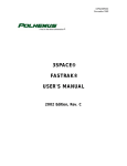
CITY AND BOROUGH OF JUNEAU (CBJ) REQUEST for QUOTES (RFQ) ENGINEERING DEPARTMENT Electric Vehicle Charging Station Installation Marine Parking Garage RFQ No. E15-117 QUOTES ARE DUE PRIOR TO 2:00 p.m., September 23, 2014 RESPONDING TO THIS REQUEST FOR QUOTES. Quotes may be hand-delivered, or faxed, to the attention of Tina Brown, CBJ Engineering, Contracts Office, 3rd Floor, Marine View Center at 230 South Franklin Street. The Engineering Department Contracts Division fax number is 907-5864530. Emailed quotes will be accepted if they are emailed to [email protected], received and printed prior to the deadline stated above. It is strongly recommended that Bidders call (907) 586-0490 to confirm receipt of faxed or emailed quotes. To be considered, Quotes must include a Bid and Signature page and Bid Schedule. SCOPE OF WORK. The Contractor shall provide all labor, equipment, materials and perform all Work as shown on attached Drawing E100 for the Electric Vehicle Charging Station Installation Marine Parking Garage, RFQ E15-117. Work shall include, but is not limited to, removal of existing circuit breaker, transformer, and primary and secondary feeders. Install new circuit breaker, panel, control enclosure, charging station, and feeders. The Electrical Vehicle charging station shall be the Eaton, Dual AC Level 2 commercial/fleet, wall mounted. The charging station shall be furnished by the Owner. The contractor shall pick up the charging station at Delta Alaska Wholesale, 2425 Industrial Boulevard, Juneau, Alaska, 907-789-0301. The site of the Work is Marine Parking Garage in downtown Juneau. The panel shall be installed in the electrical area on the first floor and the charging station shall be installed on the concrete wall as shown by the Owner at space number 25. Provide supports and hardware as required. All Work shall be in accordance with the CBJ Standard Details, 4th Edition, August 2011 and the Standard Specifications for Civil Engineering Projects and Subdivision Improvements, December 2003 Edition, and current errata, unless otherwise indicated in this RFQ document. COMPLETION TIME FOR THE WORK. The Contractor shall have until October 31, 2014, to complete all Work as described. SITE INSPECTION. Bidders are encouraged to visit the Project site prior to submitting a bid for this Work. Failure to visit the site shall in no way relieve the Contractor of its responsibility to perform the Work in compliance with the terms and specifications of this Contract. QUALITY OF WORK. The Contractor shall employ workers and craftspeople qualified in the necessary trades. All Work shall conform to the drawings and specifications, industry standards and practices, and the manufacturer’s requirements. The Contractor shall be responsible for the supervision and control of all Work; the safety of the workers; and assurance that the quality of Work and character of workers conform to all applicable laws and regulations. Electric Vehicle Charging Station Installation Marine Parking Garage RFQ No. E15-117 Page 1 QUALIFICATIONS. By submitting a quote the Contractor warrants that it is qualified to perform the Work described in accordance with all applicable codes, standards, and regulations. The Contractor shall, upon request by the CBJ, provide all documentation showing the Contractor’s qualifications and/or registrations necessary for completion of the Project. QUOTES. A Quote for the Work will not be accepted from a Contractor who does not hold a valid Alaska Business License and a valid Contractor’s license in Alaska (applicable to the type of Work bid upon) at the time of opening Bids. The CBJ’s procurement code requires that Request for Quotes be used for projects estimated to not exceed $50,000.00 in total cost. If a quote is submitted for an amount exceeding $50,000.00, it shall be considered non-responsive. AWARD. Award of this Quote, if it is awarded, will be on the basis of materials and equipment described in these RFQ documents and will be made to the lowest responsive, responsible Bidder whose Bid complies with all the requirements prescribed. CONTRACTOR’S RESPONSIBILITIES. The Contractor shall designate a Construction Superintendent, or designee, who shall serve as the Contractor’s point of contact and be in full charge of the Work, ensuring that construction is performed in a safe and professional manner. Unless otherwise approved in writing by the Owner’s Project Representative, the Construction Superintendent shall acknowledge and accept, on behalf of the Contractor, all written change orders, directives, approval, or rejection notices. The Contractor shall have sole responsibility for the means, methods, sequences, or procedures of construction and safety precautions related thereto. The Contractor shall conduct all Work in such a manner as to protect CBJ resources. The Contractor shall comply with all applicable laws, regulations, codes, and ordinances. In addition, the Contractor shall obtain applicable licenses and permits, unless directed otherwise; provide supervision, labor, tools and new materials, unless directed otherwise. SUBCONTRACTING. If this project will have subcontractors, the Contractor shall submit a list of Subcontractors who will be working on the project (form attached to the end of this RFQ), and to comply with Alaska Department of Labor Wage and Hour requirements and the Alaska Employment Security Act. The Employment Security Tax Clearance form will be issued with the Notice to Proceed. CANCELLATION. The CBJ, as Owner, reserves the sole right to cancel this Contract, in whole or in part, immediately, in the event of the Contractor’s failure to perform the Work in conformance with these Contract Documents. CONTRACT ADMINISTRATION AND ACCEPTANCE. The CBJ, through its authorized representative, will perform the Contract Administration and Inspection for this Work. The CBJ reserves the right to determine the acceptability of the finished Project. Should the Contractor fail to meet the required specifications, the Contractor shall immediately complete the Project as specified, at no additional cost to the CBJ. COMPENSATION. The Contractor shall be paid on a lump sum basis, upon satisfactory completion and acceptance of the Work by the CBJ and notification by the State Department of Labor that the Contractor has complied with its requirements. Electric Vehicle Charging Station Installation Marine Parking Garage RFQ No. E15-117 Page 2 LIABILITY AND INSURANCE REQUIREMENTS. Liability. The Contractor shall hold and save the CBJ, its officers, agents, and employees harmless from liability of any nature. This includes any costs, expenses, suits or damages of any kind sustained by any person(s) or property by any virtue of performance resulting from the Project, unless arising from carelessness or negligence by the CBJ, which will be apportioned on a comparative fault basis. Insurance Requirements. The Contractor shall provide evidence of insurance with a carrier or carriers satisfactory to the CBJ, covering injury to persons and/or property suffered by the CBJ or a third party, as a result of operations under this contract by the Contractor or by any Subcontractor. This coverage will also provide protection against injuries to all employees of the Contractor and the employees of any Subcontractor engaged in Work under this contract. The delivery to the CBJ of a written 30-day notice is required before cancellation of any coverage of reduction in any limits of liability. Insurance carriers providing coverage shall have an A.M. Best rating of at least A-VII. The Contractor shall maintain in force at all time, during the performance of Work under this contract, the following policies of insurance. “The CBJ shall be named as additional insured for any and all work performed for the CBJ.” (Additional insured requirements not required for Worker’s Compensation coverage.) Proof of this insurance is required before the final bid award. 1. Workers’ Compensation Insurance. The Contractor, if subject to the provisions of the Alaska Workers’ Compensation Act (AS 23.30), will provide the CBJ and the State of Alaska with proof, furnished by the insurance carrier, of current coverage for workers compensation with an insurance company or association authorized to transact such business in the State of Alaska, or an approved current certification of self-insurance by the Alaska Workers’ Compensation Board. The Contractor further acknowledges and agrees that in the event it fails to maintain proper Workers’ Compensation coverage, the State will implement the provisions of AS 23.30.045 8 and CBJ, at its option, may terminate this agreement for cause without liability. a. 2. Employers Liability Bodily Injury by Accident: Bodily Injury by Disease: Bodily Injury by Disease: $100,000.00 Each Accident $100,000.00 Each Employee $500,000.00 Policy Limit b. The Contractor agrees to waive all rights of subrogation against the Owner for Work performed under the contract. c. If the Contractor directly utilizes labor outside of the State of Alaska in the prosecution of the Work, ”Other States” endorsement shall be required as a condition of the contract. Commercial General Liability Insurance. Such insurance shall cover all operations by, or on behalf of, the Contractor providing insurance for bodily injury and property damage liability including coverage for premises and operations, products and completed operations, contractual liability, broad form property damage, and personal injury liability. The minimum limits of liability shall be: $1,000,000 each occurrence for General Liability and Products/Completed Operations; $1,000,000 for Personal Injury Liability; Electric Vehicle Charging Station Installation Marine Parking Garage RFQ No. E15-117 Page 3 $2,000,000 Aggregate for Products-Completed Operations; $2,000,000 General Aggregate. 3. Business Automobile Insurance. $1,000,000 per accident, combined single limit, covering owned, non-owned and hired automobiles. The City and Borough of Juneau shall be named as an “Additional Insured” for all coverages listed above, except Workers’ Compensation. TITLE 36 (Little Davis-Bacon) REQUIREMENTS. If your quote exceeds $25,000.00 and you subcontract or employ anyone to perform any of the Work, the following will apply: State of Alaska, Department of Labor, Laborers’ and Mechanics’ Minimum Rates of Pay, AS 36.05.010 and AS 36.05.050, Wage and Hour Administration Pamphlet No. 600, the latest edition published by the State of Alaska, Department of Labor inclusive, are made a part of this contract by reference. The CONTRACTOR is responsible for contacting the Alaska Department of Labor to determine compliance with current regulations. Correspondence regarding Title 36 requirements may be submitted electronically or paper copies can be submitted by mail. To submit Title 36 documents electronically, go to https://myalaska.state.ak.us/home/app. If filing electronically, submit certified payrolls to ADOL at the website above and email a copy of all certified payrolls to the Contract Administrator at the email address below. If Contractor elects to submit paper copies, they should be submitted to the physical addresses below. Within 10 Days of "Notice of Award/Notice to Proceed" make a list of all Subcontractors. Include their name, address, phone, estimated subcontract amount, and estimated start and finish dates. Send this list to the Wage and Hour Section (contact information below). Certified Payrolls must be submitted every two weeks. Before the second Friday, each CONTRACTOR and Subcontractor must file Certified Payrolls with Statements of Compliance for the previous two weeks. Indicate "Start" on your first payroll, and "Final" on your last payroll for this Project. As part of the final payment request package, CONTRACTOR must submit a “NOTICE OF COMPLETION OF PUBLIC WORKS” form signed by ADOL personnel. Contact Information: Wage and Hour Section State of Alaska Department of Labor and Workforce Development Labor Standards and Safety Division and Wage and Hour Administration P.O. Box 11149 Juneau, AK 99811-1149 907-465-4842 http://labor.state.ak.us/lss/home.htm Greg Smith, Contract Administrator City and Borough of Juneau 155 S. Seward Street Juneau, AK 99801 (907) 586-0873 [email protected] Electric Vehicle Charging Station Installation Marine Parking Garage RFQ No. E15-117 Page 4 If you need additional information, contact the State of Alaska, Department of Labor at 465-4842. QUESTIONS CONCERNING THE WORK. Contact the Contract Administrator. FINAL PAYMENT. Prior to final payment of the final 5% of this contract, the Contractor must submit the following documents: 1. Employment Security Tax Clearance for the Contractor and each Subcontractor from Alaska Department of Labor, Juneau Field Tax Office – (form to be provided with Notice to Proceed) 2. Compliance Certificate and Release Form – (form to be provided with Notice to Proceed) 3. Approved Notice of Completion of Public Works (from DOL) if project exceeds $25,000. AS-BUILT PLANS. This request for bids may include a portion of an as-built plan. As-built plans are prepared from the best available information; however, the plans may not reflect actual utility locations. The CBJ is not responsible for costs incurred by the Contractor due to any discrepancy in the as-built plans. TECHNICAL SPECIFICATIONS/DRAWING INDEX 1. E-100 Construction Drawing 2. Photograph of Charging Station Installation Location 3. Electric Vehicle Charging Station Specification Sheet 4. Electric Vehicle Charging Station Installation and Service Manual Electric Vehicle Charging Station Installation Marine Parking Garage RFQ No. E15-117 Page 5 BID AND SIGNATURE PAGE Project: RFQ E15-117 Electric Vehicle Charging Station Installation Marine Parking Garage Dated: Bidder: (Company Name) By: (Signature) Printed Name: Email: Title: Telephone No.: Address: (Street or P.O. Box) Fax No.: (City/State and Zip Code) _______________________________________________________________________ The Contractor shall provide all labor, equipment, materials and perform all Work as described in the Scope of Work. COMPLETION TIME FOR THE WORK. The Contractor shall have until October 31, 2014, to complete all Work as described. Bidder has examined the bid documents, including the following addenda (receipt of all of which is hereby acknowledged by the undersigned). Give number and date of each Addenda below. Failure to acknowledge receipt of all Addenda may cause the Bid to be non-responsive and may cause its rejection. Addenda No. Date Issued Addenda No. Date Issued TO BE CONSIDERED, ALL BIDDERS MUST COMPLETE AND INCLUDE THE FOLLOWING AT THE DATE AND TIME QUOTES ARE DUE: Signed Bid and Signature Page, (includes Addenda receipt statement) Completed Bid Schedule Electric Vehicle Charging Station Installation Marine Parking Garage RFQ No. E15-117 Page 6 BID SCHEDULE BASE BID UNIT PRICE ITEM NO. Item 1 BID ITEM DESCRIPTION Contractor shall perform all Work as shown on attached Drawing E100 for the Electric Vehicle Charging Station Installation Marine Parking Garage, RFQ E15-117. Total Bid PAY UNIT APPROX. QUANTITY DOLLARS CENTS Lump Sum All Req'd Lump Sum AMOUNT DOLLARS $ Company Name Electric Vehicle Charging Station Installation Marine Parking Garage RFQ No. E15-117 Page 7 CENTS Standard Terms and Conditions Examination of Quote Documents: Each bidder shall thoroughly examine and be familiar with all the documents and any addenda to those documents. The submission of an Quote shall constitute an acknowledgment that the bidder has thoroughly examined and is familiar with the Request For Quote (RFQ) documents. The failure or neglect of a bidder to receive or examine any of the Quote documents shall in no way relieve that bidder from any obligations with respect to that bidder's proposal, or to the contract. Misinterpretation or a claimed lack of knowledge concerning the Quote will not serve as a basis for a claim for additional compensation. Interpretation of Quote Documents: Comments concerning defects, questionable or objectionable material and requests for interpretation must be made in writing and received by the CBJ Engineering Department, Contracts Office. If required, amendments to the Quote documents will be in the form of an addenda and, when issued, will be sent as promptly as is practical to all parties to whom the RFQ documents have been issued. All such addenda shall become part of the contract. Request must be sent to the CBJ Engineering Department, Contracts Office, 155 South Seward Street, Juneau, Alaska 99801. Preparation of Quote: Quote must be submitted on the RFQ forms provided, or copies thereof, and be completed in all respects as required by the RFQ documents. Each Quote shall include all information requested, and be manually signed in ink. Addenda: Each Quote shall include acknowledgment in the space provided (Item 2), in the RFQ form, receipt of all addenda issued during the bidding period. Failure to acknowledge all addenda may result in the proposal being rejected as not responsive. It shall be the bidder's responsibility to inquire about addenda issued. Qualification of Bidders: Each bidder shall be skilled and regularly engaged in the general class or type of work called for under the contract. If requested by the CBJ Engineering Department, the low bidder shall submit resumes, documentation or information explaining, illustrating, or demonstrating the experience of the firm, and its key personnel who will be assigned to this contract. Specifications: Unless otherwise specified in the RFQ, product brand names or model numbers specified in this RFQ are examples of the type and quality of product required, and are not statements of preference. If the specifications describing an item conflict with a brand name or model number describing the item, the specifications govern. Reference to brand name or number does not preclude an offer of a comparable or better product, if full specifications and descriptive literature is provided for the product. Failure to provide such specifications and descriptive literature may be cause for rejection of the offer. Quote Prices: The bid prices shall include everything necessary for the fulfillment of the contract, including, but not limited to, furnishing all materials, equipment and labor, except as may be provided otherwise in the contract documents. Price bid must be in U.S. Funds. Additional Units on RFQ Award: The CBJ may from time to time request additional units above the amount stated in the RFQ, realizing that additional orders constituting more than 25% of the amount stated in the RFQ would be with the concurrence of the Contractor. Extension of Prices: In case of error in the extension of prices in the Quote, the unit prices will govern; in a lot bid, the lot prices will govern. Firm Offer: For the purpose of award, offers made in accordance with this RFQ must be held firm for a period of ninety (90) days from the date of RFQ opening. Contract Extensions: Unless otherwise provided in the RFQ, the CBJ and successful bidder/Contractor agrees: (1) that any holding over of the contract excluding any exercised renewal options, will be considered as a month-to-month extension, and all other terms and conditions shall remain in full force and effect, and (2) to provide written notice to the other party of the intent to cancel such month-tomonth extension. Default: In case of default by the Contractor, for any reason whatsoever, the CBJ may procure the goods or services from another source and hold the Contractor responsible for any resulting excess cost and may seek other remedies under law or equity. Billing Instructions: Except as specifically allowed under the RFQ, invoices must be billed to the Engineering Department, as noted on the purchase order. The ordering agency will approve for payment after it receives the merchandise or service and all conditions of the RFQ have been met. Equal Employment Opportunity: The CBJ is an affirmative action purchaser and encourages small and disadvantaged businesses to submit bids. Rejection of Quotes: The CBJ reserves the right to reject any or all bids and to determine which bid, if any, should be accepted in the best interest of the CBJ. The CBJ reserves the right to waive any Informality in a quote. Electric Vehicle Charging Station Installation Marine Parking Garage RFQ No. E15-117 Page 8 Fax/Email Disclaimer: It is the responsibility of the bidder to respond in a timely manner. Bidders' use of a facsimile machine or email shall be at bidders' sole risk. The CBJ will attempt to keep its facsimile machine and email system in good working order but will not be responsible for bids that are late due to mechanical failure, a busy facsimile machine, or any other technical issue arising from bidders' use of a facsimile machine or email, even if bidder submits a transmission report or provides other confirmation indicating that the bidder transmitted a bid before the submittal deadline. Bidders are therefore strongly encouraged to confirm receipt of their bid with the CBJ prior to submittal deadline. INDEMNIFICATION: The Contractor agrees to defend, indemnify, and hold harmless CBJ, its employees, volunteers, consultants, and insurers, with respect to any action, claim, or lawsuit arising out of or related to the Contractor’s performance of this contract without limitation as to the amount of fees, and without limitation as to any damages, cost or expense resulting from settlement, judgment, or verdict, and includes the award of any attorneys fees even if in excess of Alaska Civil Rule 82. This indemnification agreement applies to the fullest extent permitted by law and is in full force and effect whenever and wherever any action, claim, or lawsuit is initiated, filed, or otherwise brought against CBJ relating to this contract. The obligations of Contractor arise immediately upon actual or constructive notice of any action, claim, or lawsuit. CBJ shall notify Contractor in a timely manner of the need for indemnification, but such notice is not a condition precedent to Contractor’s obligations and may be waived where the Contractor has actual notice. CONTRACTOR’S GOOD STANDING WITH CBJ FINANCE DEPARTMENT: Contractors must be in good standing with the CBJ prior to award, and prior to any contract renewals, and in any event no later than seven business days following notification by the CBJ of intent to award. Good standing means: all amounts owed to the CBJ are current and the Contractor is not delinquent with respect to any taxes, fees, assessment, or other monies due and owed the CBJ, or a Confession of Judgment has been executed and the Contractor is in compliance with the terms of any stipulation associated with the Confession of Judgment, including being current as to any installment payments due; and Contractor is current in all CBJ reporting obligations (such as sales tax registration and reporting and business personal property declarations). Failure to meet these requirements may be cause for rejection of your bid. To determine if your business is in good standing, or for further information, contact the CBJ Finance Department’s Sales Tax Division at (907) 586-5265 for sales tax issues, Assessor’s Office at (907)5860930 for business personal property issues, or Collections Division at (907) 586-5268 for all other accounts. RESPONSIBLE BIDDER. Only responsive Bids from responsible Bidders will be considered. A Bid submitted by a Bidder determined to be not responsible may be rejected. A responsible Bidder is one who is considered to be capable of performing the WORK. NON-RESPONSIVE BIDS. Only responsive Bids will be considered. Bids may be considered nonresponsive and may be rejected. Some of the reasons a Bid may be rejected for being nonresponsive are: If a Bid is received after the Deadline for Bids. If the Bid is on a form other than that furnished by the OWNER, or legible copies thereof; or if the form is altered or any part thereof is detached; or if the Bid is improperly signed. If there are unauthorized additions, conditional or alternate Bids, or irregularities of any kind which may tend to make the bid incomplete, indefinite, ambiguous as to its meaning, or in conflict with the OWNER’s Bid document. If the Bid does not contain a Unit Price for each pay item listed, except in the case of authorized alternate pay items. If the Bidder has not acknowledged receipt of each Addendum. If any of the Unit Prices Bid are excessively unbalanced (either above or below the amount of a reasonable Bid) to the potential detriment of the OWNER. Electric Vehicle Charging Station Installation Marine Parking Garage RFQ No. E15-117 Page 9 LIST OF SUBCONTRACTORS (AS 36.30.115) RFQ E15-117 – Electric Vehicle Charging Station Installation Marine Parking Garage 1 SUBCONTRACTOR ADDRESS 1. AK Contractor License No. 2 AK Business 1 Contact Name Type of 2 Phone Number Work 1 Contract Amount DBE? $ 2 2. 1 $ 2 3. 1 $ 2 4. 1 $ 2 I certify that the above listed Alaska Business License(s) and CONTRACTOR Registration(s), if applicable, were valid at the time Bids were opened for this Project. CONTRACTOR, Authorized Signature CONTRACTOR, Printed Name Electric Vehicle Charging Station Installation Marine Parking Garage RFQ No. E15-117 Page 10 Technical Data TD191002EN Effective July 2013 Dual AC Level 2 commercial/fleet electric vehicle charging station For more information about Eaton’s electric vehicle solutions, scan this QR Code. Product family overview The use of plug-in electric vehicles is increasing in the marketplace and this develops the need for an optimized charging infrastructure that can simultaneously charge multiple vehicles while leveraging the least amount of existing real estate. The dual connector Level 2 charging station—Eaton’s latest addition to our family of EV charging stations—is specifically designed to meet this need. Ideal for commercial parking spaces, multifamily dwellings and fleets, Eaton’s featurerich product will greatly reduce your upfront infrastructure and installation costs. Product description Configuration options are available from parallel 30A to parallel 70A of power output, making Eaton’s dual connector charging station the only product in the marketplace to support simultaneous, independent charge sessions of up to 70A. This range supports today’s existing J1772 compatible vehicles and ensures future operability as vehicle manufacturers may upgrade their on-board equipment to support faster charging. Available in wallmount and pedestal types, our stations will adapt to your preferred location and usage scenario. The consumer interface is simple to operate and features language agnostic indicator icons and matching English text. User authentication, payment processing, and network management are optionally available through integrated ChargePoint.T The stations can also optionally support a credit card swipe pay-as-yougo platform using integrated reader and payment processing managed by USA Technologies. Standard features • Dual connector simultaneous AC Level 2 charging—208 Vac or 240 Vac • NEMAT 3R exterior housing • Eaton’s standard one-year warranty on all electrical components and housing per Selling Policy 25-000 Standards compliance • SAE J1772 conductive charge couplers • NFPAT 70 National Electrical Code,T Article 625 Electric Vehicle Charging System • ULT 2231 personnel protection systems for EV charging circuits • UL 2594 EV supply equipment (outline of investigation) • UL 1998 software in programmable components • CSAT C22.2 No. 107.1 • FCC compliant Technical Data TD191002EN Dual AC Level 2 commercial/fleet electric vehicle charging station Effective July 2013 Table 1. Catalog Numbering System S D R 3 B B CR 00 00 Optional Accessories d Product Family Communications c S = Charging station Station Type a C = Dual wall D = Dual pedestal E = Dual wall with L1 outlet F = Dual pedestal with L1 outlet Enclosure Cable Length R = NEMA 3R P = Custom paint 3 = 18 ft 4 = 23 ft Continuous Ampere Rating b B = 30A C = 48A D = 70A X =Basic hardware (serial, Modbus RTU) B=ChargePoint Network enabled— GSM/GPRS USA C =ChargePoint Network enabled— GSM/GPRS Canada D=ChargePoint Network enabled—CDMA 00 =No accessory CC=Credit card swipe CP=ChargePoint card only CR=ChargePoint card and contactless credit card a Wallmount stations are only available with 30A dual output ratings. b Upstream breaker shall be sized in accordance with NFPA 70 National Electrical Code (NECT), Article 625.14 (USA) or Canadian Electrical Code (CEC) Part 1 Section 86 (Canada). Each output connector will need its own dedicated upstream circuit breaker. For example, a dual 70A station will need two 90A breakers upstream of it. c Communications options are not available for wallmount stations. d Only one optional accessory may be configured with each station. Stations configured with ChargePoint communications should also have either a CP or CR accessory. Each optional accessory will manage user access to either connector output. NNote: Sample catalog number configuration above shows a Level 2 dual-pedestal EVSE, NEMA 3R enclosure, 18-foot cable, 30A, ChargePoint Network enabled with ChargePoint card and contactless credit card. Specifications Table 2. Technical Specifications (30–70A configurations) Table 3. Physical and Environmental Specifications Description Description Incoming voltage and connections 208–240 Vac, Line 1, Line 2, and Earth ground Input frequency 50/60 Hz 30A 70A Output amperage—max. continuous (per connector) a Interlocked power output Yes Overcurrent rating Output amperage +5% Ground fault interruption 20 mA (UL 2231-1 / UL 2231-2 personnel protection) Automatic reset after DIP switch selectable Enable/Disable nuisance trip feature (default Enabled) Cold-load pickup (randomized restart on Yes power failure/delay before charging resumes after a power failure) Mechanical operations 10,000 cycles (EV connector, replaceable) 100,000 cycles (contactor, replaceable) De-energization on breakaway Yes Cable length Dimensions H x W x D in inches (mm) Surge withstand a Consult factory for additional lengths. Up to 6 kV at 3000A Soft start Wallmount Pedestal Available up to 23 feet a 22.00 x 15.00 x 8.00 53.00 x 15.00 x 8.00 (558.8 x 381.0 x 203.2) (1347.0 x 381.0 x 203.2) Add 9 inches below for cable hanger 65 75 110 (includes skid) 120 (includes skid) Six LEDs: Power, Charging, Complete, Remotely Controlled, Temporary Fault, and Service Fault Reset (resets temporary faults) IP14 Weight unpackaged Weight packaged Status indicators Pushbuttons Ingress protection Type rating Temperature—storage Temperature—operating Humidity 3R –30 to 80°C –30 to 50°C 90% RH, noncondensing No—Field selectable (DIP switch) a Upstream breaker shall be sized in accordance with NFPA 70 National Electrical Code (NEC), Article 625.14 (USA) or Canadian Electrical Code (CEC) Part 1 Section 86 (Canada). Each output connector will need its own dedicated upstream circuit breaker. For example, a dual 70A station will need two 90A breakers upstream of it. Table 4. I/O Specifications Description Table 5. Optional Specifications Wallmount J1772 pistol-grip EV connector Permissive run contact Current control to vehicle RS-485 Field diagnostics and upgrade port 2 eaton www.eaton.com Pedestal Same as output rating NC dry contact input 4–20 mA analog input Modbus RTU four-wire port RS-232 DB9 (Telnet support) Description Cellular a Credit card processing ChargePoint Network Wallmount/Pedestal GSM/GPRS or CDMA a PCI-DSS Enables connectivity to ChargePoint Network b a Required for ChargePoint communications. b Requires ChargePoint communications and accessory options and a service plan. Technical Data TD191002EN Dual AC Level 2 commercial/fleet electric vehicle charging station Effective July 2013 Installation The electric requirements and wiring installation procedure for electric vehicle charging stations vary by form-factor, but can easily be performed by any qualified electrician. Per NEC Article 625 (USA) and CEC Part 1 Section 86 (Canada), each vehicle connection requires a dedicated circuit. For the dual AC Level 2 charging station, a separate circuit must exist for each connector. See installation guide IM0EV00002E for more details. For more information, visit www.eaton.com/plugin, call 855-ETN-EVSE (855-386-3873), or call your local Eaton sales office. Dimensions Dimensions in inches (mm) 15.37 (390.4) 11.23 (285.2) 7.50 (190.5) 2.38 (2) (60.5) 6.05 (153.7) Shown with Level 1 Option 23.25 (590.6) 30.13 (765.3) 20.98 (532.9) 17.35 (440.7) 12.40 (315.0) 8.00 (203.2) 3.00 (76.2) 5.75 (146.1) 5.00 (127.0) 4.75 (120.7) 10.00 (254.0) LH Side View Front View RH Side View Figure 1. Wallmount eaton www.eaton.com 3 Technical Data TD191002EN Dual AC Level 2 commercial/fleet electric vehicle charging station Effective July 2013 Dimensions Dimensions in inches (mm) 2.38 (2) (60.5) 8.35 (212.1) 15.37 (390.4) Shown with Level 1 Option 50.03 (1270.8) 43.16 (1096.3) 40.88 (1088.4) 26.58 (675.1) 32.30 (820.4) 25.90 (675.9) 21.90 (556.3) 5.12 (130.0) 3.94 (100.1) 5.18 (131.6) 10.30 (261.6) 3.00 (76.2) 4.91 (124.7) 7.88 (200.2) 16.41 (416.8) LH Side View Front View RH Side View Figure 2. Pedestal For more information, visit www.eaton.com/plugin, call 1-855-ETN-EVSE (1-855-386-3873), or call your local Eaton sales office. Eaton 1000 Eaton Boulevard Cleveland, OH 44122 United States Eaton.com Electrical Sector Canadian Operations 5050 Mainway Burlington, ON L7L 5Z1 Canada EatonCanada.ca © 2013 Eaton All Rights Reserved Printed in USA Publication No. TD191002EN / Z13939 July 2013 Eaton is a registered trademark. All other trademarks are property of their respective owners. Instruction Manual IM0EV00002E Effective April 2012 Installation and Service Manual Level 2 AC Pow-R-Station™ Electric Vehicle Supply Equipment (EVSE) Contents DescriptionPage 1. Important Safety Instructions- Please Read . . 2 2. Symbols and Definitions. . . . . . . . . . . . . . . . . 2 3. About the Pow-R-Station EV Charging Station. . . . . . . . . . . . . . . . . . . . . . . . . . . . . . . 3 4.Installation. . . . . . . . . . . . . . . . . . . . . . . . . . . . 4 5. Installing the Electrical Service. . . . . . . . . . . . 6 6. Instructions for Opening Door Latch . . . . . . . 7 7. Installing to the Premise. . . . . . . . . . . . . . . . . 8 8. Termination and Configuration. . . . . . . . . . . . 10 9. Confirming Installation and First Use . . . . . . 12 10.Installation Validation for Communications Connectivity. . . . . . . . . . . . . . . . . . . . . . . . . . 14 11.Specifications . . . . . . . . . . . . . . . . . . . . . . . . 17 12Appendix. . . . . . . . . . . . . . . . . . . . . . . . . . . . 18 For more information, visit www.eaton.com/plugin, call 1-855-ETN-EVSE (1-855-386-3873), or call your local Eaton sales office. Instruction Manual IM0EV00002E Effective April 2012 1. Important Safety Instructions - Please Read WARNING ELECTRICAL This equipment should be installed, adjusted, and serviced by qualified electrical personnel familiar with the construction and operation of this type of equipment and the hazards involved. Failure to observe this precaution could result in death or severe injury Installation and Service Manual Level 2 AC Pow-R-Station™ Electric Vehicle Supply Equipment (EVSE) Definitions AC – Alternating Current. The type of power available in most buildings and on utility poles. The Pow-R-Station EVSE protects Users and vehicles by allowing AC power to flow through it to the vehicle. The vehicle then converts the AC to DC (Direct Current) to charge the traction battery. ALC – Available Line Current. The Pow-R-Station EVSE tells the vehicle through the J1772™ connector’s pilot pin how much current (in amperes) it is allowed to pull on the circuit. This allows the car to not exceed the circuit’s maximum current rating. Read this manual thoroughly and make sure you understand the procedures before you attempt to operate this equipment. EVSE – Electric Vehicle Supply Equipment. EVSE is a general term used for all of the equipment used to supply electricity to the car, such as the Eaton Pow-R-Station EVSE. The purpose of this manual is to provide you with information necessary to safely operate, maintain, and troubleshoot this equipment. Keep this manual for future reference. GFCI – Ground Fault Current Interrupter. GFCI protects Users from faults involving leakage currents going to ground, rather than the proper return path of the circuit. Do not use this product if the EV Cable is frayed, has damaged insulation or any other sign of damage. J1772™ – The SAE Recommended Practice for conductive charging of hybrid and electric vehicles. This standard spells out the physical dimensions of the J1772 connector and the pilot communication between the plug-in vehicle and EVSE. Do not use this product if the enclosure or the EV connector is broken, cracked, open, or show any other indication of damage. Intended for use with plug-in electric vehicles only. Premise ventilation not required. The information contained in this manual is subject to change without notice. 2. Symbols and Definitions WARNING ELECTRICAL This symbol indicates high voltage. It calls your attention to items or operations that could be dangerous to you and other persons operating this equipment. Read the message and follow the instructions carefully. WARNING Indicates a potentially hazardous situation which, if not avoided, can result in serious injury or death. caution Indicates a potential hazardous situation which, if not avoided, can result in minor to moderate injury, or serious damage to the equipment. The situation described in the CAUTION may, if not avoided, lead to serious results. Important safety measures are described in CAUTION (as well as WARNING). important Indicates a particular item or instruction this is important to consider. Save These Instructions 2 eaton corporation www.eaton.com Pilot – The signal through the J1772 connector. This signal tells both the vehicle and the EVSE when both are ready to charge and how much current it is allowed to pull. This signal is a SAE standard. Plug Session – The time while the EVSE is plugged into a vehicle. It starts by plugging in the J1772 connector and ends when unplugging the same connector. SAE – Society of Automotive Engineers. The group that organizes and leads committees of transportation experts to create standards, such as J1772, for the transportation industry. Traction Battery – The large battery on a plug-in electric vehicle that is used to store and release energy for propulsion. This is different than the 12V battery that is used to start the vehicle initially and run accessories such as the radio. UI – The User Interface part of the unit. TB – The Terminal Block is where the incoming field power will be terminated in the EVSE unit. ADA – Americans with Disabilities ACT. Installation and Service Manual Level 2 AC Pow-R-Station™ Electric Vehicle Supply Equipment (EVSE) 3. About the Pow-R-Station EV Charging Station Eaton’s Pow-R-Station is Electric Vehicle Supply Equipment (EVSE) and is compatible with the Society of Automotive Engineers J1772™ standard for charging plug-in hybrid and all-electric vehicles. The Pow-R-Station EV Charging Station has several safety features: • Protects Users with interlocked power – the cable and pins have no power on them until the connector is safely plugged into a vehicle • Protects Users from temporary faults – and automatically resets* so no User interaction is needed. • Instructs the vehicle on how much current to draw – keeps the upstream circuit protection from ‘nuisance tripping’. • Allows integration into authorization and management systems – keeping only authorized personnel able to use units and power usage levels to predefined levels. • See section ‘Specifications’ for more details *Automatic Reset feature must be enabled during installation – see page 15 for more information. Moving, Transporting and Storage Instructions Store this unit indoors and in its original packaging until it is ready to be installed. Storage temperature should be between -30° and 80° C. When moving or lifting the unit always grasp the unit enclosure. NEVER attempt to lift, move, or carry the unit by the EV cable. DO NOT carry the unit by the cable hook assembly. Improper storage or handling may cause damage to the unit. Before You Begin WARNING ELECTRICAL WARNING – ONLY QUALIFIED PERSONNEL FAMILIAR WITH THE OPERATION AND CONSTRUCTION OF THIS EQUIPMENT SHOULD INSTALL, ADJUST, MODIFY, AND SERVICE THIS EQUIPMENT. FAILURE TO FOLLOW THE INSTRUCTIONS COULD RESULT IN SEVERE BODILY INJURY OR DEATH. important The user is responsible for conforming to all local and National Electric Code® standards applicable in the environment that the Pow-R-Station is being installed and commissioned. Instruction Manual IM0EV00002E Effective April 2012 ADA Standards for Accessible Design It is very important to consider all STANDARDS FOR ACCESSIBLE DESIGN for Americans with Disabilities when choosing the location and placement of all Electric Vehicle Supply Equipment. The following is a direct excerpt from the 2010 ADA Standards for Accessible Design (http://www.ada.gov/regs2010/2010ADAStandards/2010ADAs tandards.htm#c3) “The Department of Justice published revised regulations for Titles II and III of the Americans with Disabilities Act of 1990 “ADA” in the Federal Register on September 15, 2010. These regulations adopted revised, enforceable accessibility standards called the 2010 ADA Standards for Accessible Design “2010 Standards” or “Standards”. The 2010 Standards set minimum requirements – both scoping and technical -- for newly designed and constructed or altered State and local government facilities, public accommodations, and commercial facilities to be readily accessible to and usable by individuals with disabilities. Adoption of the 2010 Standards also establishes a revised reference point for Title II entities that choose to make structural changes to existing facilities to meet their program accessibility requirements; and it establishes a similar reference for Title III entities undertaking readily achievable barrier removal. The Department has assembled this online version of the official 2010 Standards to increase its ease of use. This version includes: 2010 Standards for State and Local Government Facilities Title II; and 2010 Standards for Public Accommodations and Commercial Facilities Title III. The Department has assembled into a separate publication the revised regulation guidance that applies to the Standards. The Department included guidance in its revised ADA regulations published on September 15, 2010. This guidance provides detailed information about the Department’s adoption of the 2010 Standards including changes to the Standards, the reasoning behind those changes, and responses to public comments received on these topics. The document, Guidance on the 2010 ADA Standards for Accessible Design, can be downloaded from: http://www.ada.gov For information about the ADA, including the revised 2010 ADA regulations, please visit the Department’s website www.ADA.gov; or, for answers to specific questions, call the toll-free ADA Information Line at 800-514-0301 (Voice) or 800-514-0383 (TTY). Replacement Parts List Table 1. Replacement Parts List. Part Part Number Protection and Control Board PCBA 91C5370G01 Cable / Connector Assembly 91C5363G02* Inlet Housing 43-276* Ribbon Cable for User Interface 91C5361G01 User Interface Unit 91C5360G01 Contactor 120V 30A 91C5362G02* Contactor 70A C25FNF37B *consult with your local sales office to confirm availability eaton corporation www.eaton.com 3 Instruction Manual IM0EV00002E Effective April 2012 4. Installation Installation and Service Manual Level 2 AC Pow-R-Station™ Electric Vehicle Supply Equipment (EVSE) In North America, it is recommended to install Pow-R-Station EVSE’s with a high focus on orientating the station toward the front and driver side of parking spaces. Suggestions for different types of parking layouts are illustrated below. Choosing a Location important THings to consider before choosing a location to mount the unit: 1. 2010 Standards for Accessible Design. 2. Consultation with an architect may be needed in order to conform to all governing standards for location and placement of Electric vehicle supply equipment. 3.location of an available mounting support - the wall mount unit must be anchored into a mounting support such as a 2 x 4 stud or solid concrete wall, using mounting hardware that is appropriate for the surface on which you are mounting. Do not mount this unit to a stucco/drywall/wallboard. 4.location of an available electrical source - power wires must be run through an approved conduit or jacket from the circuit panel to the unit. 5.location of the vehicle's charging inlet while parked the unit must be located so its respective cable length is right-sized to where the vehicle's inlet is for plug-in without undue maneuvering. Figure 2. 90 Degree Parking. NNote: These installation location recommendations are based upon general purpose parking, trying to serve the most likely plug-in vehicle drivers. For specific parking, such as at home or in a captive fleet scenario where the User knows where the vehicle’s inlet will be, locate the Pow-R-Station appropriately. Each plug-in electric vehicle manufacturer has a different location for where the charging inlet is located on the vehicle. Figure 3. 45 Degree Parking. Figure 1. Vehicle Inlet Locations Differ by Manufacturer. 4 eaton corporation www.eaton.com Installation and Service Manual Level 2 AC Pow-R-Station™ Electric Vehicle Supply Equipment (EVSE) Instruction Manual IM0EV00002E Effective April 2012 Wheel stops are recommended to be installed at a minimum distance of four feet from the front of the Pow-R-Station EVSE to the vehicle side of the wheel stop for general purpose parking. This distance takes into effect when larger vehicles, like the backing up of a pickup truck with a trailer hitch, back into such a space. For fleet customer with specific vehicles or for parking restricted to plug-in vehicles only, the wheel stop installation distance may be different. Figure 4. Parking Bay/Garage. NNote: The wall-mount style of Pow-R-Station can come with a much longer cord, so in Parking Bays and Garages, length of the cord is less of a problem for maintenance. Protecting the Location For outdoor installations, creative use of protective bollards and wheel stops are necessary. Vehicles can and will damage the units if left unprotected. Figure 6. Protecting the Pow-R-Station EVSE with Bollards (for Reference Only). Protective bollards are recommended to be installed in the area in close proximity of the Pow-R-Station EVSE. See local jurisdiction requirements for actual specifications. Figure 5. Protecting the Pow-R-Station EVSE with Wheel Stops for General Purpose Parking. eaton corporation www.eaton.com 5 Installation and Service Manual Level 2 AC Pow-R-Station™ Electric Vehicle Supply Equipment (EVSE) Instruction Manual IM0EV00002E Effective April 2012 WARNING ELECTRICAL 5. Installing the Electrical Service Checking the Electrical Requirements The National Electric Code®, Article 625.21 states “Overcurrent protection for feeders and branch circuits supplying electric vehicle supply equipment shall be sized for continuous duty and shall have a rating of not less than 125 percent of the maximum load of the electric vehicle supply equipment.” A load study of the location’s electrical service may be needed to determine the availability of adequate electrical service. Take the nameplate amperage rating of the Pow-R-Station, and multiply by 125% for the minimum upstream circuit protection needed. Check your local jurisdictions for any other electrical requirements. WARNING – LOCKOUT/TAGOUT ALL ELECTRICAL SOURCE CIRCUITS FEEDING THE UNIT(S) IN THE OPEN POSITION BEFORE BEGINNING WIRING OR TERMINATIONS. FAILURE TO FOLLOW THE INSTRUCTIONS COULD RESULT IN SEVERE BODILY INJURY OR DEATH. WARNING This unit is rated for indoor or outdoor installation. If this unit is mounted outdoors, the hardware for connecting the conduits to the unit must be rated for outdoor installation and be installed properly to maintain the proper NEMA 3R rating on the unit. Running the Wires Once the proper electrical overcurrent device has been installed, wire needs to be run from it to the Pow-R-Station EVSE. For a typical installation, the only field wires will be for the incoming electrical service. If the EVSE has a Level 1 option, additional service and wiring will be needed. If the EVSE unit has a remote management option, a standard CAT5/6 network cable or 3-wire shielded cable typical for a RS485 type network could also need to be run to the unit. The Pow-R-Station operates on a single-phase service – two hots, and one ground. important Confirm with the local electrical requirements for the gauge, temperature rating, and type of wire material used for the overcurrent rating found below. The chart shows a general recommendation. Table 2. Electrical Wire Chart Style Nameplate Overcurrent Suggested Suggested Suggested Rating Wire Gauge Wire Type Wire Temp Rating SAR_B* 30A 40A 8 AWG Copper 75 degrees C −− THE 30A LEVEL 2 EVSE REQUIRES A DEDICATED 208/240VAC 40A UPSTREAM BREAKER. SAR_C* 70A 90A 4 AWG Copper 75 degrees C −− THE 70A LEVEL 2 EVSE REQUIRES A DEDICATED 208/240VAC 90A UPSTREAM BREAKER. SBR_B* 30A 40A 8 AWG Copper 75 degrees C SBR_C* 70A 90A 4 AWG Copper 75 degrees C NNote: Use Copper Conductors ONLY. IMPORTANT −− OPTIONAL LEVEL 1 OUTLET REQUIRES DEDICATED 120VAC 20A UPSTREAM BREAKER. −− DO NOT USE GFCI BREAKERS. GFCI EXISTS IN EVSE AND ON LEVEL 1 OUTLET. For detail on termination of Level 1 option see page 10. 6 eaton corporation www.eaton.com Wall-mount Pedestal Installation and Service Manual Level 2 AC Pow-R-Station™ Electric Vehicle Supply Equipment (EVSE) Instruction Manual IM0EV00002E Effective April 2012 6. Instructions for Opening Door Latch Step 3. Step 1. Rotate the handle counter-clockwise to release latch as shown in Figure 9. The door should pop open. Facing the charging station, locate the door latch on the right side of the unit as shown in Figure 7. Figure 9. Rotate Handle to Release Latch Figure 7. Door Latch. . Step 2. Insert key into lock and turn counter-clockwise (note: for new installations the key will come already in the lock). Once unlocked, the latch should pop outwards as shown in Figure 8. Figure 8. Unlocked Door Latch. eaton corporation www.eaton.com 7 Instruction Manual IM0EV00002E Effective April 2012 Installation and Service Manual Level 2 AC Pow-R-Station™ Electric Vehicle Supply Equipment (EVSE) 7. Installing to the Premise The three typical installation methods of installing Pow-R-Station EVSE’s to the premise are found below. Some installations require installing the wall-mount style of Pow-R-Station EVSE to a wall or unistrut. Mounting to a Wall Preparing the Site Once a proper site has been chosen and the electrical service has been run to the location, you can begin installation. caution DO NOT MOUNT UNIT TO ONLY STUCCO/DRYWALL/WALLBOARD. DO NOT USE TOGGLE BOLTS, ZIP ANCHORS, NOR PLASTIC WALL ANCHORS MEANT FOR THESE MATERIALS BECAUSE THEY DO NOT HAVE THE STRENGTH NEEDED TO SUPPORT THE UNIT. THE UNIT MUST BE MOUNTED TO A SOLID SUPPORT SUCH AS: WOOD, CONCRETE WALL, CONCRETE BLOCK WALL, OR EQUIVALENT. Step 1: Remove the mounting plate from the back of the EVSE unit by placing the unit on a solid non-scratch surface and opening the unit by turning the latch on the side. Remove the three nuts on the 10-32 studs that attach the mounting plate to the unit. The location of these mounting studs can be seen in Figure 10. Save these nuts and washers as they will be needed to re-attach the unit later in the installation. Step 2: Using the mounting plate as a template, mark the holes to be used for mounting. Make sure the mounting plate is level. If mounting on a wood stud wall use the two center holes. If mounting on a solid wall such as concrete, brick, or concrete block, use the four outside square holes. Step 3: Pre-drill mounting holes if mounting into a wood stud or drill appropriate sized holes in a solid wall for use with the type of anchor you will be using. Step 4: Attach mounting plate to the wall as shown in Figure 11. If installing on a wood stud, use 5/16” or 3/8” x 3” long Lag screws and washers. These should be galvanized or stainless steel for weather protection if mounting outdoors. If mounting onto a concrete, block, or brick wall, use an appropriate anchor for the type of wall on which you are installing the unit. Again, these should be appropriate for weather conditions if mounting outside. Figure 11. Typical Wall Mounting. Figure 10. Unit and Mounting Plate. 8 eaton corporation www.eaton.com Step 5: After the mounting plate is secure to the wall, mount the EVSE unit to the mounting plate using the washers and nuts removed in Step 1. Installation and Service Manual Level 2 AC Pow-R-Station™ Electric Vehicle Supply Equipment (EVSE) Mounting to Uni-Strut Once a proper site has been chosen and the electrical service has been run to the location, you can begin installation. Step 1: Remove the mounting plate from the back of the EVSE unit by placing the unit on a solid non-scratch surface and opening the unit by turning the latch on the side (for details, see Section 6. Instructions for Opening Door Latch). Remove the three nuts on the 10-32 studs that attach the mounting plate to the unit. The location of these mounting studs can be seen in Figure 10. Save these nuts and washers as they will be needed to re-attach the unit later in the installation. Step 2: Using the mounting plate as a template, determine where the anchors should be placed to be used for mounting. It Instruction Manual IM0EV00002E Effective April 2012 is recommended in high wind and use area, cross-arms should be used to avoid twisting which can occur in a single pole installation. Make sure the mounting plate is level. If mounting on a single pole use the two center holes. If mounting utilizing cross-arms use the four outside square holes. Step 3: Attach mounting plate using as shown in Figure 12. Use appropriate hardware making sure it is galvanized or stainless steel for weather protection if mounting outdoors. Step 4:After the mounting plate is securely attached to the mounting structure, mount the EVSE unit to the mounting plate using the washers and nuts removed in Step 1. Figure 12. Typical Unistrut Mounting. Figure 13. Dimensional Detail for Unistrut Mounting. eaton corporation www.eaton.com 9 Instruction Manual IM0EV00002E Effective April 2012 Installation and Service Manual Level 2 AC Pow-R-Station™ Electric Vehicle Supply Equipment (EVSE) Figure 14. Base Detail Pedestal for EVSE. Pedestal Floor Mounting 8. Termination and Configuration Preparing the Site Once a proper site has been chosen and the electrical service has been run to the location, you can begin installation. Step 1: Open door using the latch on the side of the unit (see Section 6. Instructions for Opening Door Latch, for details). Step 2: Remove the bottom pan by pulling upward and then angling outward. Best if performed when door is held opened. Step 3: The hole pattern for the base of the pedestal mount is shown below in Figure 14. Use six, 3/8 UNC Grade 5 stainless bolts torqued at 50 ft-lbs for mounting base to the ground. NNote: If using a concrete pad, please be mindful of the overall height of the unit due to ADA Compliance. Please reference the ADA Compliance section of this document. WARNING ELECTRICAL WARNING – LOCKOUT/TAGOUT ALL ELECTRICAL SOURCE CIRCUITS FEEDING THE UNIT(S) IN THE OPEN POSITION BEFORE BEGINNING WIRING OR TERMINATIONS. FAILURE TO FOLLOW THE INSTRUCTIONS COULD RESULT IN SEVERE BODILY INJURY OR DEATH. WARNING – ONLY QUALIFIED PERSONNEL FAMILIAR WITH THE OPERATION AND CONSTRUCTION OF THIS EQUIPMENT SHOULD INSTALL, ADJUST, MODIFY, AND SERVICE THIS EQUIPMENT. FAILURE TO FOLLOW THE INSTRUCTIONS COULD RESULT IN SEVERE BODILY INJURY OR DEATH. Wire Terminations For a typical installation, the only field wire terminations will be the incoming electrical service wires. If the EVSE unit is configured for Pow-R-Station Network Manager or other remote management solution, a standard CAT5/6 network cable or 3-wire shielded cable for RS-485 Communications. Electrical Service Wires Terminate the incoming electrical service wires to the Pow-R-Station EVSE’s provided terminal block, following the designations for each wire. L1, L2, and G (see Figure 15). 10 eaton corporation www.eaton.com Installation and Service Manual Level 2 AC Pow-R-Station™ Electric Vehicle Supply Equipment (EVSE) Instruction Manual IM0EV00002E Effective April 2012 Figure 15. Electrical Service Wiring. NNote: Torque for incoming field service wiring – 22.1 - 26.6 in-lb (2.5 – 3.0 Nm) – Use Copper Conductors Only. Grounding Instructions This product must be connected to a grounded, metal, permanent wiring system; or an equipment-grounding conductor must be run with the circuit conductors and connected to the equipment grounding terminal. Optional Level 1 - 120VAC Outlet When the EVSE is equipped with a Level 1 - 120VAC Outlet perform the wiring instructions outlined below in Figure 16. Level 1 Field Connection Diagram GFCI Receptacle Figure 17. GFCI Receptacle Location - Reference Only Control Wires RJ45 CAT5/6 network cable or a 4-wire shielded Belden cable for Modbus communication may be needed based upon the configuration of your Pow-R-Station. Terminate these wires before applying the electrical service wires. If none present, skip this step and go to the next section. Figure 16. Optional Level 1 - 120VAC Outlet Figure 18. Control Wiring. eaton corporation www.eaton.com 11 Instruction Manual IM0EV00002E Effective April 2012 Installation and Service Manual Level 2 AC Pow-R-Station™ Electric Vehicle Supply Equipment (EVSE) 9. Confirming Installation and First Use Figure 19. Status Indicators. Step 1: Ensure that the electrical service wires are landed according to this manual. Make sure the station access door is closed. Step 2: Power ON the Distribution Breaker. Step 3: During initial EVSE boot-up, the User Interface will cycle all ICONs. Step 4: After boot-up, the Power ICON will be either STEADY or BLINKING per above table. If this is not the case, please verify that all incoming service connections are landed appropriately and that the distribution breaker is in-tact. If the Power ICON still does not appear, please call technical support. 12 eaton corporation www.eaton.com Step 5: If the Power ICON is BLINKING, Authorization is needed. Please consult the Authorization section of this document below. If the Power ICON is STEADY, please proceed to the next step. Step 6: If a SAE J1772 Compliant Electric Vehicle is available, please connect the EV Connector to the Vehicle Inlet. You may also use an Eaton Vehicle Simulator. Step 7: The CHARGING INDICATOR will begin to blink. Step 8: Almost immediately, the vehicle will engage a charge session (the contactor will close and power will be supplied to the vehicle). See Table 10: Normal Operation User Interface Indicators, in the Appendix, for more details. Installation and Service Manual Level 2 AC Pow-R-Station™ Electric Vehicle Supply Equipment (EVSE) Step 9: When power is being supplied to the vehicle, the CHARGING INDICATOR will move from a BLINK status to STEADY status signifying that current is flowing to the vehicle. Step 10: You may now remove the connector from the vehicle at your leisure. Authorization Needed: If Authorization is needed, the Power ICON will have a BLINK pattern. This signifies to the end User that either payment activation is needed or RFID authorization. Ground Fault Test Figure 20. Ground Fault Test. The ground fault detection feature is self tested every time the unit starts a plug session to charge a vehicle. A User can manually test the ground fault feature at any time by pressing and holding the reset button (right button) for seven seconds. If the test passed successfully, the fault light will flash once. If it detects a problem, the power icon will turn off and the service light (wrench icon) will have a medium single blink until power is cycled to the unit. See Table 11: EVSE Fault or Error User Interface Indicators, in the Troubleshooting Section in the Appendix, for more details. Instruction Manual IM0EV00002E Effective April 2012 • To Enable Automatic Reset: Dip Switch Block SW2, Position 6 must be ON. • To Disable Automatic Reset: Dip Switch Block SW2, Position 6 must be OFF. For board replacements or basic confirmation of settings, Table 3 contains the explanation of the dip switch settings found in the corner of the Eaton Protection and Control Board (EPCB) near the RS232 Serial port, labeled SW1 and SW2. Table 3. Dip Switch Settings. Dip Switch Block Dip Switch Position Feature SW2 1 SW2 ON OFF Description Voltage US 120V Configuration US 208/240V Voltage Configuration of the Unit. For 120V Configuration – A Wire Jumper needs to be added between L2 and N on Figure 15 of this Document. 2 Operating Frequency 50Hz North America is 60Hz SW2 3, 4, and 5 Reserved for Factory Use SW2 6 Auto-reset after fault Enabled SW2 7 Soft Start Default in OFF Position. If ON, the EVSE will perform a ramp up of current to the Available Line Current (ALC) or Nameplate Rating over a 30 second time period. This is done through the SAE J1772 handshake with the vehicle by modifying the Duty Cycle on the Pilot Signal. SW2 8 Reserved for Factory Default in OFF position SW1 1 Reserved for Factory Default in OFF position SW1 2 and 3 RS485 Baud Rate See Baud Rate Dip Switch Table – Default is all ON SW1 4, 5, 6, 7, and 8 RS485 Address 60Hz Dip Switch Settings caution Modifying the DIP Switch Configuration of the Unit could cause the unit not to operate as desired. Please only modify dip switch settings if you absolutely understand the impact to the unit. Automatic Reset Feature From the manufacturer, the Pow-R-Station is set to require a manual reset after a temporary fault. The User has to opt-in to enable the automatic reset feature. Reserved for Factory Use. Disabled Comes from the factory disabled. A vehicle fault must be reset manually – the owner can easily enable this feature via this dip switch. Doing so, will enable an auto-reclosure on a nuisance trip Range 0x00 to 0x1F using binary addressing (Most Significant Bit being SW1- Position 4). Default is all OFF except Position 8, i.e. 0x01. Table 4. RS485 Baud Rate Dip Switch Table. Baud Rate SW1 – Position 2 SW1 – Position 3 9600 OFF OFF 19200 OFF ON 38400 ON OFF 115200 ON ON Figure 21. Enabling/Disabling Automatic Reset. During installation, the Automatic Reset setting can be either left disabled as it came from the factory, or the User can decide to enable the feature. To enable or disable this feature, a Service Technician must change the position of a dip switch on the control board. eaton corporation www.eaton.com 13 Installation and Service Manual Level 2 AC Pow-R-Station™ Electric Vehicle Supply Equipment (EVSE) Instruction Manual IM0EV00002E Effective April 2012 SW1 Communications to Network Manager 7 7 6 4 3 2 ON 1 4 2 1 3 5 5 6 8 8 SW2 ON 10. Installation Validation for Communications Connectivity Figure 22. Dip Switch Settings for a 208/240V, 60Hz, 30A Pow-RStation with Auto-reset DISABLED. There are several communication options to enable connectivity to Network Manager available for Pow-R-Station EVSE. The following instructions detail the validation procedures for confirming connectivity for cellular, Wi-Fi, and Ethernet communication options. Please note that in order for the unit to connect to Network Manager via Wi-Fi and Ethernet connections, the local area network must have access to the following two web addresses: • Address 1: endpoint.gridpoint.com • Address 2: ems.gridpoint.com Please confirm access to these sites with the facility’s IT department. Ethernet Connectivity If the EVSE is setup to connect via hardwired Ethernet over Cat5/6e cable: Step 1 Verify the network providing the Ethernet service to the EVSE has DHCP enabled or if there are any firewalls on the Ethernet drop. Ask facility’s IT if you are not sure. Ensure firewalls will not prevent the Network Manager Controller from connecting to gridpoint.com. Step 2 Disconnect the Ethernet Cable from the Network Manager Controller (See Figure 23). Figure 23. Disconnecting Ethernet cable from Network Manager Controller. 14 eaton corporation www.eaton.com Installation and Service Manual Level 2 AC Pow-R-Station™ Electric Vehicle Supply Equipment (EVSE) Instruction Manual IM0EV00002E Effective April 2012 Step 3 Step 4 Use an RJ45 coupler to connect the Ethernet cable that was just disconnected from the Network Manager Controller to an RJ45 cable and PC as shown in Figure 24. Setup your PC to obtain an IP address automatically. PC RJ45 Cable RJ45 Coupler RJ45 Cable to Network Figure 24. Ethernet cable connected to RJ45 cable and PC. a.On test PC running Windows XP navigate to Start > Control Panel > Network Connections and double click on the Local Area Connection icon. This will open the connection status window for that Ethernet connection. b.Note: Local Area Connection may be a different name depending on how your Ethernet port is setup or if there are multiple Ethernet ports on the test PC. Make sure the next steps are done on the Ethernet port that the modem is connected to on the test PC. c.Go to Properties in the General tab. This will open the Connection Properties window. See Figure 25. d.Double click on the Internet Protocol (TCP/IP) selection. See Figure 25. e.Make sure the “Obtain an IP address automatically” is selected. See Figure 25. Figure 25. PC setup. eaton corporation www.eaton.com 15 Installation and Service Manual Level 2 AC Pow-R-Station™ Electric Vehicle Supply Equipment (EVSE) Instruction Manual IM0EV00002E Effective April 2012 f. Hit Ok for the two windows to close them. Cellular Connectivity g.In the Local Area Connection Status, go to the support tab and verify that an IP address has been assigned. Jot down the Default Gateway address for the Wifi Troubleshooting portion. Step 1 NNote: It does not need to match exact numbers in Figure 26. Please safely energize the unit. The Ethernet Port LED Lights on the Network Manager Controller should now be lit. Step 2: After approximately two minutes, verify that the LED indicator lights on the Cellular Modem are lit according to the following pattern: • Power: Solid • Network: Solid • Signal: • Solid (very strong) • Fast Blink (strong) • Normal Blink (good) • Slow Blink (weak) • None (no signal) Figure 27. Cellular Model LED Indicator Lights. Step 3: To verify connectivity, call GridPoint technical support at 1-866-800and provide them with the Network Manager controller serial number. For more information about setting up connectivity to Network Manager, see the Network Manager quick start guide (document IL0EV00006E). Wi-Fi Connectivity Figure 26. Support tab of Local Area Connection Status. Step 5 Once an IP address is assigned to the PC, open an internet browser and go to a website like gridpoint.com. If the Ethernet service is open it should allow for any popular website to be accessed. Step 6 If you are able to access a website, then you have verified that the Ethernet service for the Network Manager Controller is properly functioning. For more information about confirming Ethernet connectivity contact Eaton Tech Support at 1-855-ETN-EVSE (386-3873) 16 eaton corporation www.eaton.com Please refer to Instructional Leaflet IL0EV00008E (Level 2 AC PowR-Station electric vehicle supply equipment Wi-Fi configuration quick start guide) to confirm Wi-Fi connectivity. Installation and Service Manual Level 2 AC Pow-R-Station™ Electric Vehicle Supply Equipment (EVSE) 11. Specifications Instruction Manual IM0EV00002E Effective April 2012 Table 6. Physical and Environmental Specifications. The Eaton Pow-R-Station EVSE is compliant with the following standards: Description Dimensions - H x W x D Wall-mount Pedestal 22” x 15” x 8” (Add 9” below for cable hanger) 52.50” x 15” x 8” • Society of Automotive Engineers (SAE) J1772™ 2010 EV Conductive Charge Coupler and Station. • NFPA 70 National Electric Code, Article 625 Electric Vehicle Charging System. • UL 2231 Personnel Protection Systems for EV Charging Circuits. Ingress Protection • UL 2594 EV Supply Equipment (Outline of Investigation). Type Rating • UL 1998 Software in Programmable Components. Temperature – Operating -30 to 50 degrees Celsius • FCC compliant, Part 15. Temperature – Storage -40 to 70 degrees Celsius Humidity 90% RH, non-condensing Status Indicators 6 LEDs: ‘Power’, ‘Charging’, ‘Complete’, ‘Remotely Controlled’, ‘Temporary Fault’, and ‘Service’ Push Buttons 2 Buttons: ‘Override’ and ‘Reset’ IP14 3R Table 5. Electrical and Mechanical Specifications. Description 30A 70A Incoming Voltage 208 VAC 240 VAC 120 VAC 208 - 240 VAC Description Input Frequency 50/60Hz 50/60Hz Incoming Amperage 40 A 90 A Output Voltage Same as Incoming Output Frequency Table 7. I/O Specifications. Same as Incoming Wall-mount J1772™ Pistol Grip EV Connector Pedestal Same as Output Rating Permissive Run Contact NC dry contact input Available Line Current Control 4 – 20mA analog input Output Amperage - Max Continuous 30A 70A RS-485 Interlocked Power Output Yes Yes Memory SD Memory Slot Ethernet RJ45, IEEE 802.3, TCP/IP, Modbus TCP Overcurrent Rating Ground Fault Interruption Output Amperage + 5% 20mA (UL2231-1/UL2231-2 Personnel Protection) Automatic Reset after Nuisance Trip Feature DIP switch selectable Enable/Disable (default Enabled) Randomized Restart On Power Failure (delay before charging resumes after a power failure) Yes Mechanical Operations 10,000 cycles (EV Connector, replaceable) 100,000 cycles (Contactor, replaceable) Incoming Field Electrical Service Terminal Block Torque in in-lb (Nm) 22.1 – 26.6 (2.5 – 3) Incoming Modbus Connections Terminal Block Torque in in-lb (Nm) 4.4 – 5.3 (.5 - .6) Modbus-RTU 4-wire port Field Diagnostics and Upgrade Port RS-232 DB9 (HyperTerminalTM Support) Table 8. Optional Specifications. Description Through-feed (Daisy Chain) Compatible Network controller Wall-mount Pedestal No Yes Enables connectivity to Pow-R-Station Network Manager with real-time status and historical information Wireless Wi-Fi (WPA or WPA2) RFID basic Basic lock/unlock with card or keyfob RFID User Customer provided third-party database of users integrated for authentication Cellular GPRS/GSM Credit Card Processing PCI-DSS Network Management Pow-R-Station Network Management Solution with Real-time Status and Historical Information Table 9. Optional Level 1 120VAC 20A Outlet . Incoming Voltage 120VAC Input Frequency 60 Hz Output Voltage Same as incoming Output Frequency Same as incoming Output Amperage - Max Continuous 20A eaton corporation www.eaton.com 17 Installation and Service Manual Level 2 AC Pow-R-Station™ Electric Vehicle Supply Equipment (EVSE) Instruction Manual IM0EV00002E Effective April 2012 Appendix Table 10. EVSE Normal Operation User Interface Indicators EVSE Normal Operation User Interface Indicators EVSE Meaning Interface Snap Shot Steady Single Blink Action Required Unit is Ready for Use Remove EV Connector from EVSE and Mate to your Electric Vehicle. Plug-In to Vehicle to Begin Charge Session Authorization is required A) If the EVSE has a RFID reader, please present your keyfob or other credential to activate. B) Otherwise proceed to process payment via Credit Card Payment System on the front of the unit. After payment is rendered, EVSE will activate and Power ICON Steady Single Blink Vehicle Connected, EVSE Ready, Waiting on Vehicle None - Waiting on Vehicle to Begin Charging. If vehicle does not begin charging momentarily, please check internal scheduling system or remove and re-insert EV Connector Steady Steady Vehicle Connected and Vehicle Charging Wait for Full Charge or Disconnect When you are Ready to Leave Steady You can now walk away from the unit. Charging will begin with Building Management System Allows. Vehicle Connected and Charging is Remotely Controlled by Building Management System Charging Set to INACTIVE Depending on Facility Setup, Local Override may be available by pushing the "Override Pushbutton" Single Blink Single Blink Steady You can now walk away from the unit. Charging will begin when Vehicle Engages Charge Session. Vehicle Connected and Charging is Remotely Controlled by Building Management System Depending on Facility Setup, Local Override may Charging Set to ACTIVE but at a reduced be available by pushing the "Override level. Pushbutton" This will request to charge at full capacity. Single Blink Steady 18 Definition Steady Single Blink Steady Steady Single Blink Steady Vehicle Connected and Current Charge Session is Complete. At anytime, you may remove the EV Connector and Re-Dock it to the EVSE. If the vehicle wants to engage a charging again at a later time while you are away, it may do so at anytime. No additional activity is required by you. Vehicle Connected and Current Charge Session is Complete. At anytime, you may remove the EV Connector and Re-Dock it to the EVSE. If the vehicle wants to engage charging again at a later time while you are away, it may do so at anytime. No additional activity is required by you. eaton corporation www.eaton.com Installation and Service Manual Level 2 AC Pow-R-Station™ Electric Vehicle Supply Equipment (EVSE) Instruction Manual IM0EV00002E Effective April 2012 Table 11. EVSE Fault or Error User Interface Indicators EVSE Fault or Error User Interface Indicators Will present itself in a blink pattern or a steady icon. Typically an internal EVSE Concern Icon Pattern Will present itself in a blink pattern or a steady icon. Typically is a vehicle related concern. Eaton defines this as a Temporary Fault or in rare occurances a Nuiscance Trip. Fault/Error Desciption SAE J1772 Concern Steady Rarely Occurs: Vehicle Nuiscance Trip Continually Occurs: Vehicle SAE J1772 Compatibility Concern Fast Double Blink In all Errors/Faults, the Power ICON will be ON or Blinking. On a few of the Errors the Charging ICON will BLINK to describe the specific Error. Recommendation / Action - Press Manual Reset Pushbutton to Clear Error. - If AutoReclosure is ENABLED, the EVSE will auto clear this error after 15 minutes. - Starting a new Plug Session will also clear the error. A new Plug Session is defined as removing the EV Connector from the Vehicle Inlet and re-inserting it into the Vehicle Inlet. - Press Manual Reset Pushbutton to Clear Error. SAE J1772 Concern Steady Slow Single Blink Fast Double Blink Rarely Occurs: Vehicle Nuiscance Trip Continually Occurs: Vehicle SAE J1772 Compatibility Concern - Starting a new Plug Session will also clear the error. A new Plug Session is defined as removing the EV Connector from the Vehicle Inlet and re-inserting it into the Vehicle Inlet. - Press Manual Reset Pushbutton to Clear Error. Ground Fault Concern Steady Slow Single Blink Steady Rarely Occurs: Vehicle Nuiscance Trip Continually Occurs: Ground/Leakage Current Detection Vehicle Tried to Pull more Power the the EVSE has instructed it to pull. Steady Slow Single Blink Slow Single Blink Rarely Occurs: Vehicle Nuiscance Trip Continually Occurs: Vehicle SAE J1772 Compatibility Concern - Starting a new Plug Session will also clear the error. A new Plug Session is defined as removing the EV Connector from the Vehicle Inlet and re-inserting it into the Vehicle Inlet. - Press Manual Reset Pushbutton to Clear Error. - Starting a new Plug Session will also clear the error. A new Plug Session is defined as removing the EV Connector from the Vehicle Inlet and re-inserting it into the Vehicle Inlet. Max Temporary Faults for One Plug Session Steady Medium Blink Steady Assymetric Double Blink Steady Steady Steady Slow Single Blink Steady Very Fast Blink Steady Asymmetric Double Blink Starting a new Plug Session will clear the error. If this occurs, 5 vehicle related concerns A new Plug Session is defined as removing the happened during 1 Plug Session. A Plug Session EV Connector from the Vehicle Inlet and reis defined as the moment the user plugs the EV inserting it into the Vehicle Inlet. Connector into his/her vehicle inlet and then removes it. GF Test Failure Prior to Engaging Charge Session Call Technical Support - 1-855-ETN-EVSE Contactor Failure The occurance of Vehicle Related Errors have reached a maxium. The unit is temporarily disabled so that an investigation can be done. - Ensure that the Incoming Electrical Wires are Landed according to the Installation Manual. - the EVSE Requires an L1, L2, and Ground. - Please consult the Installation Guide for further details. Call Technical Support - 1-855-ETN-EVSE Unit is locked out and not operable Call Technical Support - 1-855-ETN-EVSE Unit is locked out and not operable Call Technical Support - 1-855-ETN-EVSE eaton corporation www.eaton.com 19 Instruction Manual IM0EV00002E Effective April 2012 Installation and Service Manual Level 2 AC Pow-R-Station™ Electric Vehicle Supply Equipment (EVSE) Eaton Corporation Electrical Sector 1111 Superior Ave. Cleveland, OH 44114 United States 877-ETN-CARE (877-386-2273) Eaton.com © 2012 Eaton Corporation All Rights Reserved Printed in USA Publication No. IM0EV00002E / TBG000585 April 2012 Eaton is a registered trademark of Eaton Corporation. All other trademarks are property of their respective owners.