1
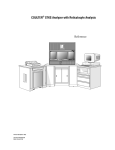
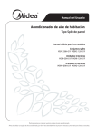
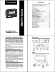
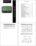
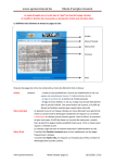
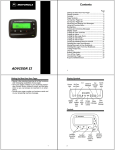
COULTER® MicroDiff
Field Service
Technical Manual
®
CC
PN 4237161B (April 1993)
TM
Coulter Corporation
Miami, FL 33196-2500
Coulter Corporation makes no representation that, upon furnishing this service manual, the holder of the manual will have the necessary
technical capabilities and know-how to properly troubleshoot and repair any of the equipment specified in the manual. Coulter
Corporation assumes no liability whatsoever, including consequential and incidental damages, resulting from improper operation of
Coulter instruments after maintenance of Coulter instruments has been performed by persons not employed by Coulter Corporation.
Furthermore, Coulter Corporation assumes no liability whatsovever for any personal injury or property damage resulting from
maintenance and/or repair of Coulter instruments performed by persons not employed by Coulter Corporation.
TRADEMARKS
AccuComp, ACCUVETTE, ACCU-ZYME, AQUA-AD, AUTO-CAL, AUTO-CLONE, "CC"
logo, CARDS, CASH, CHANNELYZER, CHEMOTERGE, COMPLETE CELL ANALYSIS,
COULTER, COULTER CHEMISTRY, COULTER CLENZ, COULTER CLONE, THE
COULTER COUNTDOWN, COULTER COUNTER, COULTER CURRENTS,
COULTERAMA, CYTO-STAT, CYTO-TROL, C-ZYME, DACAL, DACOS, "DACOS" logo,
DART, DIFF3, DIFF3 50, DIFF4, DILU-PACK, E.A.SY. 1, EASY 88, EASY 2, EPICS,
FASTECS, 5C, 4C, HEMO-CAL, HEMOTERGE, HEMO-W, IsoFlow, ISOLYSE, ISOPET,
ISOTERGE, ISOTON, KEM-O-MAT, "LFI" logo, LANGLEY FORD, LANGLEY FORD
INSTRUMENTS, LEASE-PAK, LYSE S, MDADS, MINI-KEM, NANO-SIZER, OMNISORP,
OptiChem, S-CAL, SOMACOUNT, SOMAFIX, SOMATON, STAIN RIGHT, STILL
COUNTING, THROMBOCOUNTER, THROMBO-FUGE, U.V.-ZYME, ZAP-OGLOBIN,
ZAPONIN and ZETAFUGE are trademarks of Coulter Corporation.
HAZARDS AND OPERATIONAL PRECAUTIONS AND LIMITATIONS
WARNINGS, CAUTIONS, and IMPORTANTS alert you as follows:
WARNING:
Might cause injury.
CAUTION:
Might cause damage to the instrument.
IMPORTANT: Might cause misleading results.
"This Service Manual contains confidential information of Coulter Corporation and its receipt or
possession does not convey any rights to reproduce, disclose its contents, or to manufacture, use, or sell
anything it may describe. Reproduction, disclosure, or use without specific written authorization of Coulter
Corporation is strictly forbidden."
REVISION STATUS
Issue
Date
Draft
5/92
Initial
5/92
A
7/92
B
4/93
PN 4237161B (April 1993)
Amended Pages
2-3, 2-4, 2-9, 2-10, 2-12, 2-15, 3-5, 3-6, Chapter 8
Software Level
1D
i
REVISION STATUS
ii
PN 4237161A (July 1992)
TABLE OF CONTENTS
1
2
PN 4237161B (April 1993)
WARNINGS AND CAUTIONS, 1-1
1.1
GENERAL SAFETY, 1-1
WARNING, 1-1
CAUTION, 1-1
IMPORTANT, 1-1
Note, 1-1
1.2
ELECTRONIC SAFETY PRECAUTIONS, 1-1
1.3
BIOLOGICAL SAFETY, 1-2
INSTRUMENT DESCRIPTION, 2-1
2.1
SPECIFICATIONS, 2-1
Dimensions/Weight, 2-1
Power, 2-1
Input, 2-1
Consumption, 2-1
Ambient Operating Temperature, 2-1
Humidity, 2-1
Recommended Reagents, 2-1
Controls and Calibrators, 2-1
Fluid Volumes, 2-2
Interfering Substances, 2-2
2.2
INTRODUCTION TO THE COULTER MicroDiff, 2-2
Function, 2-2
Mode of Operation, 2-2
2.3
DIFFERENTIAL MEASUREMENT, 2-2
2.4
OPERATIONAL OVERVIEW, 2-2
2.5
DILUTER, 2-3
General, 2-3
Count Valve 1 (VL1), 2-5
Dilution Valve 2 (VL2), 2-5
Stepper Motor Driver Card, 2-5
2.6
VENT VALVE VACUUM SENSE CARD, 2-8
2.7
ELECTRONICS ASSEMBLY, 2-8
General, 2-8
Motherboard, 2-9
Linear Power Supply, 2-10
iii
TABLE OF CONTENTS
Power Supply Components, 2-10
Switching Power Supply, 2-13
Data Acquisition Card, 2-14
Multi Stepper Motor Control Card (MSMC), 2-15
Input Output Resource Adapter Card (IORA), 2-17
Keyboard, 2-18
Display, 2-19
3
4
iv
MICRODIFF INSTALLATION PROCEDURE, 3-1
3.1
PREINSTALLATION CHECKS, 3-1
Space and accessibility, 3-1
Power Requirements, 3-1
Ambient Temperature and Humidity, 3-1
3.2
INITIAL SETUP, 3-2
Uncrating Instrument, Accessories and
Supplies, 3-2
Reagent Connections, 3-2
Printer Connection, 3-3
Power ON, 3-3
3.3
INSTRUMENT CONFIGURATION, 3-3
3.4
PRELIMINARY OPERATION CHECKS, 3-4
3.5
SETTING AIM FACTORS, 3-5
3.6
CALIBRATION, 3-5
3.7
RUNNING CONTROLS, 3-6
SERVICE/REPAIR PROCEDURES, 4-1
4.1
TOOLS AND EQUIPMENT REQUIRED, 4-1
4.2
DRIVER CARD REPLACEMENT, 4-1
Removal, 4-1
Installation, 4-1
4.3
PVAC CARD REPLACEMENT, 4-1
Installation, 4-2
4.4
MOTHERBOARD REPLACEMENT, 4-2
Removal, 4-2
Installation, 4-3
4.5
SYRINGE REPLACEMENT, 4-3
Removal, 4-3
Installation, 4-4
PN 4237161A (July 1992)
TABLE OF CONTENTS
PN 4237161B (April 1993)
4.6
VACUUM PUMP REPLACEMENT, 4-4
Removal, 4-4
Installation, 4-4
4.7
LYSE PUMP REPLACEMENT, 4-5
Removal, 4-5
Installation, 4-5
4.8
LYSE PUMP VERIFICATION/ADJUSTMENT, 4-5
4.9
SWITCHING POWER SUPPLY REPLACEMENT, 4-6
Removal, 4-6
Installation, 4-6
4.10
DISKETTE DRIVE REPLACEMENT, 4-7
Removal, 4-7
Installation, 4-7
4.11
DAC CARD REPLACEMENT, 4-7
Removal, 4-7
Installation, 4-8
4.12
MSMC CARD REPLACEMENT, 4-8
Removal, 4-8
Installation, 4-8
4.13
IORA CARD REPLACEMENT, 4-8
Removal, 4-8
Installation, 4-9
4.14
DISPLAY REPLACEMENT, 4-9
Removal, 4-9
Installation, 4-9
4.15
KEYPAD REPLACEMENT, 4-10
Removal, 4-10
Installation, 4-10
4.16
RED/WHITE BATH/APERTURE COMPONENT
REPLACEMENT, 4-11
Hgb Detector/LED, 4-11
Removal, 4-11
Installation, 4-12
Aperture Electrode Housing
Replacement, 4-12
Removal, 4-12
Installation, 4-13
Bath, 4-13
Removal, 4-13
Installation, 4-14
v
TABLE OF CONTENTS
CHAPTER 5 INTENTIONALLY OMITTED
6
SCHEMATIC DIAGRAMS, 6-1
CHAPTER 7 INTENTIONALLY OMITTED
8
ILLUSTRATED PARTS LIST, 8-1
8.1
PARTS LIST IN PART NUMBER ORDER, 8-1
8.2
ILLUSTRATED PARTS LISTS, 8-6
APPENDIX A ERROR CODES, A-1
A.1
MicroDiff ERROR CODES, A-1
ILLUSTRATIONS
2.1
2.2
2.3
2.4
2.5
2.6
2.7
2.8
Diluter Components, 2-4
Stepper Motor Driver Card, 2-6
Motherboard, 2-9
Linear Power Supply, 2-11
Regulator Card, 2-12
Data Acquisition Card, 2-14
Multi Stepper Motor Control Card, 2-16
Input/Output Resource Adapter Card, 2-18
8.1
8.2
8.3
8.4
8.5
8.6
8.7
8.8
Diluter, 8-6
Syringe Drive, 8-8
Linear Power Supply, 8-10
Bath, Rear View, 8-11
Bath, Front View, 8-12
Keypad and Display, 8-13
Diluent and Count Valve Display, 8-14
Carriage Assembly, 8-16
TABLES
2.1
2.2
2.3
2.4
2.5
vi
Stepper Motor Driver Card Connections, 2-7
Stepper Motor Driver Card Test Points, 2-8
Terminal Block Connections, 2-12
MSMC Jumpers, 2-17
IORA Jumpers, 2-7
PN 4237161A (July 1992)
WARNINGS AND CAUTIONS 1
1.1 GENERAL SAFETY
Throughout this manual you will encounter the headings WARNING,
CAUTION, IMPORTANT, and Note. These are provided to inform you
of potentially hazardous situations and important or helpful information.
WARNING
A WARNING indicates a situation or procedure that, if ignored, can
cause serious personal injury. A WARNING will appear in bolded text
for easy identification.
CAUTION
A CAUTION indicates a situation or procedure that, if ignored, can
cause damage to equipment. A CAUTION also appears in bolded text.
IMPORTANT
An IMPORTANT indicates a situation or procedure that, if ignored can
result in erroneous test results. An IMPORTANT also appears in bolded
text.
Note
A Note contains information that is important to remember or helpful in
performing a procedure.
1.2 ELECTRONIC SAFETY PRECAUTIONS
WARNING
Remove rings and other metal jewelry before performing maintenance
or service on the electronic components of instrument.
PN 4237161A (July 1992)
1-1
WARNINGS AND CAUTIONS
CAUTION
To prevent damage to delicate electronic components, always be sure
power is OFF before removing or replacing printed circuit boards and
components.
1.3 BIOLOGICAL SAFETY
WARNING
To prevent possible injury or biological contamination, service
personnel must wear gloves and eye protection when servicing the
instrument with the doors open.
Use care when working with pathogenic materials. Means must be
available to decontaminate the instrument, provide ventilation, and to
dispose of waste liquid. Refer to the following publications for further
guidance on decontamination.
Biohazards Safety Guide, 1974, National Institute of Health.
Classifications of Etiological Agents on the Basis of Hazards, 3d ed.,
June 1974, Center for Disease Control, U.S. Public Health Service.
In areas of high risk, operator must be trained in person. Telephone
instruction is prohibited.
1-2
PN 4237161A (July 1992)
INSTRUMENT DESCRIPTION 2
2.1 SPECIFICATIONS
Dimensions/Weight
Height
Width
Depth
Weight
49.5 cm (19.5 in.)
43.2 cm (17 in.)
40.6 cm (16 in.)
34 Kg (75 lb)
Power
Input
•
•
•
•
100 Vac (±10%) 50/60 Hz
120 Vac (±10%) 50/60 Hz
220 Vac (±10%) 50/60 Hz
240 Vac (±10%) 50/60 Hz
Consumption
Less than 200 watts
Ambient Operating Temperature
16°C to 32°C (60°F to 90°F)
Humidity
0 to 95% without condensation
Recommended Reagents
COULTER MICRO-PAK (diluent and lytic reagent) P/N 8547007
COULTER CLENZ® Cleaning Agent P/N 8546931
Controls and Calibrators
4C® PLUS Cell Control Tri Pac P/N 7547003
S-CAL® Calibrator Kit P/N 7547005
PN 4237161B (April 1993)
2-1
INSTRUMENT DESCRIPTION
Fluid Volumes
•
•
•
Whole Blood Aspirated: 12 µL
ISOTON® III diluent consumption per cycle: 18.64 mL
LYSE S® III Diff reagent consumption per cycle: 415 µL
Interfering Substances
Refer to Product Reference Manual for known interfering substances
2.2 INTRODUCTION TO THE COULTER MicroDiff
Function
The MicroDiff is an automated hematology analyzer for in vitro
diagnostic use in clinical laboratories. The MicroDiff reports a 16
parameter Complete Blood Count, including a six parameter WBC
differential, from whole blood.
Mode of Operation
The MicroDiff has one operating mode. The sample is introduced to the
instrument by removing the cap from the sample tube, presenting the
sample to the aspirator probe, and starting the cycle.
2.3 DIFFERENTIAL MEASUREMENT
The MicroDiff performs WBC differentials from whole-blood samples. It
provides lymphocyte, monocyte and granulocyte percentages and
absolute numbers using Coulter histogram differential technology.
The white blood cells are counted and sized for the WBC histogram in a
single 100-µm WBC aperture.
2.4 OPERATIONAL OVERVIEW
The cycle is started by pressing the 〈ASP〉 button on the keypad:
2-2
1.
The aspirate syringe is driven down to aspirates 12 µL of sample and
a small amount of air.
2.
The diluent syringe fills with diluent for the WBC dilution.
3.
The bath drains.
PN 4237161B (April 1993)
OPERATIONAL OVERVIEW
4.
The aspirator probe moves to the bath and dispenses the sample into
the bath. The diluent syringe dispenses diluent through the probe
into the bath making a 215:1 dilution.
5.
Mixing bubbles from the air pump (PM1) enter the bath to mix the
solution.
6.
The aspirate syringe is driven down again to aspirate 100 µl of the
dilution from the bath into the probe, where it is held for the
RBC/Plt dilution.
7.
The lyse pump (PM5) dispenses 415 µL of lyse to the bath for a final
WBC dilution of 251:1 and the sample is mixed again.
8.
The WBC solution is drawn through the WBC aperture for 12 s to
count and size the WBCs.
9.
After WBC analysis, and just before the WBC sample drains from
the bath, the Hgb reading is taken.
10. The bath is drained and rinsed and Hgb Blank is taken.
|
|
11. The diluent syringe fills with diluent for the RBC/Plt dilution.
12. The 100 µL of the 215:1 solution, stored in the aspirate probe, is
dispensed into the bath with diluent to obtain a final RBC/Plt
dilution of 6250:1.
13. Mixing bubbles from PM1 enter the bath to mix the solution.
14. The RBC/Plt dilution is drawn through the RBC/Plt aperture for 12 s
to count and size the RBCs and Plts.
15. The bath is drained and rinsed.
16. The aperture is zapped, and the system is prepared for the next test
sequence.
|
2.5 DILUTER
General
The diluter section of the MicroDiff processes the sample for analysis.
The locations of the components are illustrated in Figure 2.1.
PN 4237161B (April 1993)
2-3
INSTRUMENT DESCRIPTION
2
1
18
3
ON/OFF
SWITCH
20
10
19
7
5
9
6
11
17
21
22
1.
2.
3.
4.
5.
6.
7.
8.
9.
10.
11.
8
14
LCD DISPLAY
KEYPAD
DISK DRIVE
ASPIRATOR PROBE
ASPIRATION SYRINGE
DILUENT SYRINGE
VL2 DILUENT VALVE
LYSE PUMP PM5
LYSE DECTECTOR
VACUUM REGULATOR
VACUUM ISOLATOR
|
15
13
12.
13.
14.
15.
16.
17.
18.
19.
20.
21.
22.
16
4
VL1 COUNT VALVE
BATH-WBC APERTURE
BATH-RBC APERTURE
HGB LED
LV3 DRAIN SOLENOID
AIR PUMP PM1
LV4 AIR MIX SOLENOID
DILUENT RESERVOIR
DILUENT PUMP PM2
RINSE PUMP PM3
WASTE PUMP PM4
12
7161-01
Figure 2.1 Diluter Components
The MicroDiff uses two syringes driven by stepper motors to aspirate
sample and deliver diluent. The syringe volumes are:
•
•
Aspirate syringe
Diluent syringe
100 µL
5000 µL
The instrument uses four stepper motor driven peristaltic pumps to
generate mixing bubbles, drain the bath, deliver rinse to the bath, and
draw diluent from diluent pack into the diluent reservoir.
Two stepper motor driven switching valves, Count Valve 1 and Dilution
Valve 2, control the flow and direction of the fluidics and pneumatics.
2-4
PN 4237161B (April 1993)
DILUTER
Count Valve 1 (VL1)
The count valve is a three-position valve that routes count vacuum to the
WBC and RBC apertures.
Dilution Valve 2 (VL2)
The dilution valve is a four-position valve that:
•
•
•
Routes diluent to the bath through the aspirate probe.
Provides a path to the diluent supply to fill diluent syringe.
Routes the sweep flow diluent from the diluent reservoir through
the sweep flow can to the RBC aperture.
Stepper Motor Driver Cards
Two Stepper Motor Driver cards, in the Diluter, provide the drive voltage
to the stepper motors, the opto switches, the lyse pump, solenoids, and
the cycle counter.
Stepper Motor Driver Card 1 drives the following components:
• Diluent Pump
• Rinse Pump
• Lyse Pump
• Diluent Reservoir Sensor
• Cycle Counter
• Air Pump
• Waste Pump
• Air Mix Solenoid
• Lyse Level Sensor
Stepper Motor Driver Card 2 drives the following components:
• Dilution Valve
• Traverse Motor
• Count Valve Motor
• Aspirate Syringe Motor
• Diluent Syringe Motor
• Vacuum Pump ON
• Dilution Valve Home Opto Switch
• Traverse Home Opto Switch
• Count Valve Opto Switch
• Aspirate Syringe Opto Switch
• Diluent Syringe Opto Switch
• Power ON
The location of the electrical connections and test points on the Stepper
Motor Driver Cards is shown in Figure 2.2. Tables 2.1 and 2.2 list the
connectors and test points.
PN 4237161B (April 1993)
2-5
INSTRUMENT DESCRIPTION
MOTOR DRIVER CARD
J18
J19
J
3
0
J21
TP5
J22
J23
J
3
1
TTTT
TTTTPPPP
PPPP1 1 1 1
98763210
J
2
9
J
2
8
TP4
J20
J17
J12
TP14
J13
J14
TP15
J15
TTTTTTTT
PPPPPPPP
11112222
98763210
J10
J
2
7
J5
J6
TP24
J7
TP25
J8
J
2
6
J3
TTTTTTTT
PPPPPPPP
22223333
89763120
TP3
J1
J
2
5
TP34
7161-02
Figure 2.2 Stepper Motor Driver Card
2-6
PN 4237161B (April 1993)
DILUTER
Table 2.1 Stepper Motor Driver Card Connections
Connector
PN 4237161B (April 1993)
Driver 1
Driver 2
J1
+24 Volts
+24 Volts
J3
MSMC 1 J1
MSMC 2 J1
J5
Not Used
Count Valve Motor
J6
Not Used
Count Valve Opto
J7
Not Used
Traverse Opto
J8
Not Used
Traverse Motor
J10
MSMC 1 J2
MSMC 2 J2
J12
Air Mix Motor
Diluent Valve Motor
J13
Not Used
Diluent Valve Opto
J14
Diluent Level Sense
Not Used
J15
Diluent Fill Motor
Not Used
J17
MSMC 1 J3
MSMC 2 J3
J18
Resistor Bank
Resistor Bank
J19
Rinse Motor
Aspirate Syringe Motor
J20
Not Used
Aspirate Syringe Opto
J21
Lyse Level Sense
Diluent Syringe Opto
J22
Waste Motor
Diluent Syringe Motor
J23
Resistor Bank
Resistor Bank
J25
Not Used
Not Used
J26
Not Used
Iso Chamber Vent Valve
J27
Air Mix Solenoid
Vacuum Sense Vent Valve
J28
Cycle Counter
Vacuum Pump ON Signal
J29
Lyse Pump
Drain Solenoid
J30
Not Used
Power ON to Relay Card
J31
Not Used
+12 Volts
2-7
INSTRUMENT DESCRIPTION
Table 2.2 Stepper Motor Driver Card Test Points
Test Points
Driver 1
Driver 2
TP3
Ground
Ground
TP4
Not Used
Aspirate Syringe Opto
TP5
Lyse Level Sense
Diluent Syringe Opto
TP6 - TP13
Stepper Motor Phases
Stepper Motor Phases
TP14
Not Used
Diluent Valve Opto
TP15
Diluent Level Sense
Not Used
TP16 - TP23
Stepper Motor Phases
Stepper Motor Phases
TP24
Not Used
Count Valve Opto
TP25
Not Used
Traverse Opto
TP26 - TP33
Stepper Motor Phases
Stepper Motor Phases
TP34
+24 Volts
+24 Volts
2.6 VENT VALVE VACUUM SENSE CARD
The Vent Valve Vacuum Sense Card (VVVS) is responsible for
monitoring the 6-in. Hg of vacuum used for count, venting the isolator
chamber when in drains, and venting the vacuum transducer to obtain
an atmosphere offset.
The output of the VVVS goes to the IORA card. the voltage for 6 in. Hg
of vacuum is 4.286 volts plus the measured atmosphere offset voltage.
2.7 ELECTRONICS ASSEMBLY
General
The Electronics Assembly of the MicroDiff is contained in a hinged
compartment at the top of the instrument. It consists of the following
subassemblies:
• Motherboard with 80386 microprocessor
• 200 watt switching power supply
• Front panel with keypad and LCD display
• 1.44 MB 3½in. floppy disk drive
• Data Acquisition Board (DAC)
• Multi Stepper Motor Controller Card (MSMC)
• Analog/Peripheral Board (IORA)
• Vacuum Sensor Amp Board (PVAC)
2-8
PN 4237161B (April 1993)
ELECTRONICS ASSEMBLY
Motherboard
The Motherboard (Figure 2.3) is an AT compatible 80386 computer. The
disk controller and serial I/O port are resident on the board. Program
software is not resident in EPROMs on the motherboard. The program is
loaded from the diskette drive into the computer’s memory.
BATTERY
3
5
2
4
1
SERIAL 1
SERIAL 2
SWITCH
IDE HARD DISK
PARALLEL
FLOPPY DISK
80387SX
4
1
4MX9 SIMM
SUPPORT
JUMPER
8742
TURBO TURBO
LED SWITCH
IDE ACTIVITY
KEYLOCK
27512
SPEAKER
RESET
7161016A
SXCAT DIAGRAM
Figure 2.3 Motherboard
Switch
PN 4237161B (April 1993)
Description
|
SW1-1
Close (On) to enable Onboard Battery.
Open (Off) to enable Offboard Battery.
|
|
SW1-2
Close (On) to Enable Battery.
Open (Off) to Disable Battery.
Must be closed for normal system operation.
|
|
|
SW1-3
Close (On) for additional wait states on IDE interface.
Open (Off) for no additional wait states.
|
|
SW1-4
Close (On) for Color Adapter.
Open (Off) for Monochrome Adapter.
This switch setting does not matter when using VGA or
EGA adapters.
|
|
|
|
2-9
INSTRUMENT DESCRIPTION
ELECTRONICS ASSEMBLY
Linear Power Supply
The Linear Power Supply (Figure 2.4) is a self contained unit located
below the Computer Chassis at the bottom of the Main Chassis
Assembly. The unit is accessible with the hinged electronics
compartment open. The Power Supply provides all the necessary dc and
ac voltages to operate the unit. The supplied voltages are:
•
•
•
•
±15 Vdc for the analog circuitry
+24 Vdc for the stepper motors and pneumatic solenoids
+240 Vdc to generate aperture current and zap volts
0.02 amp constant current source for the Hgb LED.
The unit supplies dc power to the following assemblies:
•
DATA ACQ and IORA Boards located in the electronics
compartment.
•
PVAC Board, and the Hgb LED assembly located in the diluter
panel.
•
Motor Driver boards located in the Main Chassis.
The unit also supplies the ac power for the Vacuum Pump, Switching
Power Supply, and the 24-volt Power Supply.
Power Supply Components
Power Supply Board: This board consists of rectifiers; filters and
regulators for ±15 V and +240 V; a constant current source for the Hgb
LED; connectors for all inputs, outputs and test points.
Power Transformer T1: T1 provides stepped down ac power to the power
supply board for the +15 volt supply, the -15 volt supply, the 240 volt
supply and the constant current source for the Hgb LED supply which is
driven from the +15 volt supply.
24V Power Transformer T2: T2 provides stepped down ac voltage for the
+24v Power Supply.
2-10
PN 4237161B (April 1993)
ELECTRONICS ASSEMBLY
LINE FILTER
REGULATOR CARD
FUSE HOLDER
OUTLET
RELAY CARD
MAIN TRANSFORMER
24V TRANSFORMER
BRIDGE RECTIFIER
24V FILTER CAPACITOR
7161-04
Figure 2.4 Linear Power Supply
J
2
J3
J4
TP7
TP9
APP CURRENT
Hgb
TP6
Hgb Ref.
TP5
+15
TP4
Gnd
TP3
-15
TP8
Gnd
TP2
240V Gnd
240V
TP1
J1
7161-05
Figure 2.5 Regulator Card
PN 4237161B (April 1993)
2-11
INSTRUMENT DESCRIPTION
ELECTRONICS ASSEMBLY
+24 Rectifier and Filter: Provides +24 Vdc for motors and solenoids.
Vacuum Pump Solid State Relay: Connects the input ac voltage to the
vacuum pump.
+24-V Relay: Connects the input ac voltage to the +24-Volt power
transformer. The signal to operate the relay comes from the MSMC Card
through the motor driver.
AC Line Filter: Filters the input ac voltage before going to the
transformers and switching power supply.
Fuses: Control the ac line voltage to the input of the instrument.
Terminal Block: Provides ac line voltage selection (see Table 2.3).
Table 2.3 Terminal Block Connections
Input Voltage
Relay Card AC Wire
Position
Jumper
100
White
Black
1
4
1&2
3&4
120
White
Black
1
6
1&2
5&6
220
White
Black
1
4
2&5
240
White
Black
1
6
2&5
|
|
The Power Transformer T1 has three secondaries that provide ac voltage
to all the supplies. The high voltage winding is surrounded by an
electrostatic shield to reduce noise induced by the ac line. All the
secondary windings of the transformer are internally fused.
The ac voltage is then distributed to the power supply card where the ac
is full wave rectified, filtered, and regulated. The regulated supplies are
protected against overload and short circuit by current foldback and
thermal shutdown.
Two input signals to the Power Supply Card come from the DAC Card.
These signals are the aperture current ON command and aperture
current control. The aperture current ON command turns on the high
voltage regulator when aperture current is required.
The aperture current control is a signal between 0 and 5 Volts that
controls the output of the high voltage regulator. The output of this
regulator controls the gain of the pre-amp section on the DAC Card.
|
2-12
The Power Supply has two fuses, F1 and F2, rated at 2.0 A for 100 Vac to
120 Vac or 1.0 Amps for 200 Vac to 240 Vac.
PN 4237161B (April 1993)
ELECTRONICS ASSEMBLY
Switching Power Supply
The Switching Power Supply is in the top chassis and provides +5 Vdc
and +12 Vdc to the CPU and associated electronics. The switching
supply also has the POWER ON switch for the system and a cooling fan.
The ac input voltage is switch selectable for 90 Vac to 130 Vac or 180
Vac to 260 Vac. The voltages developed are plus and minus 5 volts and
plus and minus 12 volts.
There are 5 connectors coming from the Switching Power Supply. A label
on the Switching Power Supply list the voltage and current for each
connector and connector pin.
CAUTION
The power connectors P4 and P5 must not be switched!! If they are
reversed the computer motherboard may be damaged. P4 should be
towards the rear of the board and P5 towards the front. Another way to
check proper connection is that the common black wires for each of the
connectors will be next to each other in the middle .
The destination of the Switching Power Supply connectors are:
P1
P2
P3
P4
P5
Spare
Spare
Diskette Drive
Computer Motherboard P1
Computer Motherboard P2
Data Acquisition Card
The Data Acquisition Card (DAC) (Figure 2.6) performs the following
functions:
PN 4237161B (April 1993)
•
Pre-Amp for RBC/PLT/WBC
•
Aperture Current Control
•
•
•
•
Aperture Cleaning Circuit
Thresholding for RBC/PLT/WBC
RBC/WBC Counting
Aperture Integrity Monitor
•
•
•
•
RBC/WBC Editing
PLT Processing
Interface to the AT bus
RBC/PLT/WBC Analog to
Digital conversion
2-13
INSTRUMENT DESCRIPTION
J6
J4
ELECTRONICS ASSEMBLY
J3 TP11 TP7 TP3 TP5
R39
J5
X7
TP1
TP6
J2 J1
Red
TP4
TP10
TP12
TP2 TP8 TP9
White
J8
METAL SHIELD
J5
1.
2.
3.
4.
5.
6.
-15
Gnd
+15
Gnd
APP I ON
APP SET
J6
1.
2.
3.
4.
5.
6.
APP ZAP
Gnd
Gnd
APP CURRENT
Gnd
Gnd
X5
X4
X3
X2
X1
7161-06
Figure 2.6 Data Acquisition Card
The Aperture Integrity Monitor (AIM) ensures that the results produced
by the instrument are not incorrect because of obstructions in or on the
apertures.
AIM uses a voltage developed from the channelizer section of the DAC
card. The voltage is derived from the 26 percentile width of the good
pulses that make it through the pulse editor. This voltage is independent
of particle size and is a measurement of the time the particle was in the
sensing zone of the aperture. The voltage is monitored for each of the
twelve 1-second count periods the instrument performs.
If the time the particle is in the sensing zone increases, the 26 percentile
voltage will rise indicating a possible clogged aperture. If the voltage
decreases, the aperture may be partially restricted which increased the
flow rate slightly which will cause the particle to pass through the
aperture sensing zone faster.
There are nine different AIM check performed on the samples to ensure
correct results.
•
2-14
The mean of the 26 percentile voltages for each second of the 12second count is less than 95.5% of the target voltage.
PN 4237161B (April 1993)
ELECTRONICS ASSEMBLY
•
The mean of the 26 percentile voltages for each second of the 12second count is greater than 105% of the target voltage.
|
•
The CV of the 26 percentile voltages for each second of the 12second count is greater than 4%. This could happen when the
aperture plugs or becomes restricted for a short time and then clears
itself.
•
The CV of the 26 percentile voltages for each second of the 12second count is less than 0.5%. This could happen when the
aperture is completely plugged the entire count period causing the
voltage to be the same for each 1-second period.
•
The CV of the ratio between the number of particles that were
counted versus the number of particles that were channelized for
each second of the 12-second count period is greater than 7.5%.
•
The ratio of channelized pulses to counted pulses must be above
0.3.
•
No single count period voteouts.
•
The MCHC is less than 25.
•
The MCHC is more than 40.
•
The (Hgb X 3) divided by HCT is greater than 1.2.
•
The (Hgb X 3) divided by HCT is less than 0.8.
|
|
|
|
Multi Stepper Motor Control Card (MSMC)
The Multi Stepper Motor Control Card (MSMC) (Figure 2.7) is
responsible for the stepper motor timing and for reading the position
sensors on the mechanical assemblies. There are two MSMC cards in the
unit, each capable of controlling 6 stepper motors.
PN 4237161B (April 1993)
2-15
INSTRUMENT DESCRIPTION
J3
ELECTRONICS ASSEMBLY
J2
TP1
TP2
J1
X5
X4
TP3
X6
X1
7161-07
X2
X3
Figure 2.7 Multi Stepper Motor Control Card
The 6 jumpers on the MSMC card must be configured as shown in Table
2.4
Table 2.4 MSMC Jumpers
Jumper
Number
Status
X1
On
Connects +5 volts via P1B #3
X2
On
Connects +5 volts via P1B #29
X3
On
Connects +5 volts via P2B #16
X4
1-3
2-3
Sets card as MSMC IRQ 11
Sets card as MSMC IRQ 12
X5
X6
2-16
Function
Sets card as MSMC 1 or 2
On
Connects the oscillator
PN 4237161B (April 1993)
ELECTRONICS ASSEMBLY
Input Output Resource Adapter Card (IORA)
The Input Output Resource Adapter (IORA) (Figure 2.8) card performs
the following functions:
•
•
•
•
•
•
•
•
Keyboard controller
Display controller
Hgb analog to digital conversion
Power supply monitoring
RAM battery backup
Vacuum pressure transducer monitoring
Option selection via 8 position dip switch
Analog to digital conversion of clog detector voltages
The 5 jumpers on the IORA card must be configured as shown in Table
2.5.
Table 2.5 IORA Jumpers
Jumper
PN 4237161B (April 1993)
Status
Function
X1
On
Connects +5 volts via P2B #16
X2
On
Connects +5 volts via P1B #29
X3
On
Connects +5 volts via P1B #3
X4
On
1 MHz Oscillator
X5
On
Interrupt Jumper
2-17
INSTRUMENT DESCRIPTION
ELECTRONICS ASSEMBLY
J5
J3
J2
J1
X5
J4
X4
T T T
T T P P P
P P 1 1 1
8 9 0 1 2
R R R R R
3 3 3 3 3
5 6 7 8 9
TP13
S1
TP7
TP5
S2
TP6
TP4
E1
TP1
TP3
TP2
P8
X1
R35
R36
R37
R38
R39
CONTRAST
Hgb 0
Hgb GAIN
A/D 0
A/D GAIN
TP8
TP9
TP10
TP11
TP12
X2
A/D INPUT
Hgb OUT
VAC XDR OUT
GND
+5 VDC
X3
7161-08
Figure 2.8 Input/Output Resource Adapter Card
Keyboard
The keyboard is a 25 key membrane keyboard. It provides the operator a
means of interfacing with the system. It consists of numeric keys 0
through 9, a negative sign (-), a decimal point (.), four cursor keys (up,
down, left, right) and nine dedicated keys (Aspirate, Analyzed, Prime,
Escape, Stop, Delete, Clear, Enter, Print). The keyboard communicates to
the IORA card via connector J3.
2-18
PN 4237161B (April 1993)
ELECTRONICS ASSEMBLY
Display
The display is a 4 line by 40 character dot matrix LCD display for
displaying menus, instructions and data. The display’s ROM module
features a 192 character set.
PN 4237161B (April 1993)
2-19
INSTRUMENT DESCRIPTION
2-20
ELECTRONICS ASSEMBLY
PN 4237161B (April 1993)
MicroDiff INSTALLATION PROCEDURE 3
3.1 PREINSTALLATION CHECKS
Verify that all of the following requirements are met before beginning
installation of the MicroDiff.
Space and accessibility
•
Check for sufficient space for the instrument, the reagents and the
printer at a comfortable working height.
•
Allow for at least 5 inches of clearance at the rear of the instrument
for air circulation.
Power Requirements
CAUTION
Do not use an extension cord.
•
Verify the ac outlet that will supply power to the MicroDiff is a threewire outlet:
100 Vac (±10%) 50/60 Hz
120 Vac (±10%) 50/60 Hz
220 Vac (±10%) 50/60 Hz
240 Vac (±10%) 50/60 Hz
•
Verify the circuit is dedicated, low noise and protected.
Ambient Temperature and Humidity
PN 4237161B (April 1993)
•
Verify with the customer that the ambient temperature at the
designated installation site is maintained between 16°C to 32°C (60°F
to 90°F).
•
Verify with the customer that the room humidity remains below 95%
without condensation.
3-1
MicroDiff INSTALLATION PROCEDURE
3.2 INITIAL SETUP
Uncrating Instrument, Accessories and Supplies
1.
Unpack all boxes.
2.
Using the packing list, verify that all items have arrived.
3.
Make sure an adequate supply of reagents, controls and calibrator are
available at the site (see Heading 2.1 Specifications).
4.
Verify that the Waste Chamber Installation Kit, PN 7547021, is
included (if required).
5.
Remove any packing or shipping material from the instrument.
6.
Open the instrument (both diluter and analyzer sections) and inspect
for shipping damage. Remove wire ties and foam insert from vacuum
pump.
7.
Verify that all safety labels are in place.
8.
Ensure that all the cable connections are tight and cards are seated
correctly.
9.
Ensure DIP switch settings on IORA card are all OFF.
10. Install the AC power interconnect cable between the diluter section
and the analyzer power supply.
11. Connect the AC line cord to the AC power outlet.
CAUTION
Do not power the instrument up until told to do so.
Reagent Connections
3-2
1.
Connect the diluent to the blue feedthrough fitting using 3202036-4
tubing and a luer fitting (P/N 6232503-8).
2.
Connect the lytic reagent to the white feedthrough fitting using
3202021-6 tubing and a luer fitting (P/N 6232503-8).
3.
Connect the waste out tubing (P/N 3202036-4) to the red feedthrough
fitting using a luer fitting (P/N 6232503-8).
PN 4237161B (April 1993)
INITIAL SETUP
Printer Connection
1.
Connect the printer cable to the 25 pin parallel connector on the rear
of the analyzer.
2.
Set DIP switch 1, position 2 to ON. All others should be OFF.
3.
Plug the printer power cord into the AC power source and power up
the printer.
4.
Load the paper into the printer and ensure proper form feed operation.
1.
Locate the system diskette and install it into the disk drive.
2.
Power up the instrument. Ensure the drive light comes on and the
system boots up. If the system does not boot, check the cable
connections and power supply voltages.
3.
The instrument will prime up the diluent reservoir and display the
main menu.
Power ON
3.3 INSTRUMENT CONFIGURATION
PN 4237161B (April 1993)
1.
Select the SPECIAL FUNCTIONS menu from the MAIN menu.
2.
Select SETUP from the SPECIAL FUNCTIONS menu.
3.
Select DATE/TIME and chose Option 1, SELECT DATE FORMAT.
Chose the date format that the customer requests.
4.
Select Option 2, CHANGE DATE AND TIME. Enter the correct date
and time.
5.
Return to SETUP and select IQAP ID #. Enter the customer’s ID if it is
available.
6.
Select PRINT OPTIONS and chose either AUTO or MAN.
7.
Select CONTROL OPTIONS. If the customer is using COULTER
controls select AUTOMATIC, if not select MANUAL.
8.
Select CALIBRATION OPTIONS. Chose AUTOMATIC if the customer
will be using S-CAL Calibrator. Otherwise select MANUAL.
9.
Select HOST OPTIONS. Set HOST COMMUNICATION OPTIONS to
ON if the customer has a host computer or OFF if no host is present.
3-3
MicroDiff INSTALLATION PROCEDURE
10. If a host is present setup the correct communication protocol.
11. Return to SPECIAL FUNCTIONS and select REAGENT LOT #. Enter
the expiration date and lot number of the reagent pack.
12. Return to SPECIAL FUNCTIONS and select SUPERVISOR.
13. Select CHANGE LIMITS. The action limits are divided into three
sections CBC-A, CBC-B, and DIFF. Enter the customer’s action limits
if they differ from the default values. Print the screen and place it in
the log book.
13. Return to the MAIN MENU.
3.4 PRELIMINARY OPERATION CHECKS
1.
Bleach the bath and apertures.
2.
Select SPECIAL FUNCTIONS from the MAIN MENU.
3.
Select DILUTER FUNCTIONS, drain the bath, and then select
DISPENSE LYSE.
4.
Perform the DISPENSE LYSE function until the pump is primed and
the lyse lines to the bath are free of bubbles. Ensure the bath does not
overflow. If necessary, drain the bath.
5.
Drain and rinse the bath two times.
6.
Return to SPECIAL FUNCTIONS menu and select SERVICE.
7.
Check vacuum from SERVICE menu. Ensure the vacuum is 6.00 in.
Hg ±0.05 in. Hg. Adjust as necessary.
8.
Select VOLTAGE DISPLAY. Ensure all power supply voltages are
correct.
9.
Verify that the HGB blank voltage is 4.25 V to 4.85 V. If the HGB blank
is not within range check for clean rinse in the bath. If the rinse is OK
adjust the HGB blank voltage on the IORA card by adjusting R37.
10. Return to the MAIN MENU.
11. Prime sweep flow lines.
3-4
a.
Attach a syringe to sweep flow line.
b.
Run a cycle.
PN 4237161B (April 1993)
PRELIMINARY OPERATION CHECKS
c.
When instrument goes to Red Count, apply vacuum to sweep
flow line with syringe.
12. Perform a background count and observe the instrument for any leaks
or excessive bubbles. Check the counts and ensure that they are within
range.
WBC 0.4
RBC 0.04
Hgb 0.2
Plt 7.0
13. Select LATEX GAIN from the SERVICE menu. Perform a latex run and
adjust the gain if necessary.
RBC voltage 141.5 V to 169.1 V
WBC voltage 100.6 V to 129.6 V
Size 98 µm ±1.5 µm
CV LIMITS
WBC = 16.0
RBC = 8.0
3.5 SETTING AIM FACTORS
1.
Bleach the aperture to ensure that it is clean.
|
2.
Run five samples of 4C Abnormal Low in RUN SAMPLE mode. After
each sample:
|
a.
Go to SUPERVISOR menu.
b.
Press 〈7〉 〈ENTER〉.
c.
Record the measured red and white values for each run.
3.
Average the measured red/white values.
|
4.
Multiply the WBC measurement value by 1.035. This will be the new
WBC target. The new target for the RBC will be the average value
determined in step 3.
|
|
|
5.
Enter the average values in the red/white target fields of the AIM
Review screen.
|
|
1.
Select the SPECIAL FUNCTIONS menu.
2.
Select the SUPERVISOR menu.
3.6 CALIBRATION
PN 4237161B (April 1993)
3-5
MicroDiff INSTALLATION PROCEDURE
|
3.
Select the AUTO CALIBRATION menu.
4.
Select the REPRODUCABILITY/CARRYOVER menu.
5.
Run 10 samples and three diluents. Ensure that the results are within
limits. If the results exceed the limits troubleshoot the cause. If the
results are OK select the CALIBRATION menu.
6.
Insert the Calibration diskette.
7.
Run 11 samples of S-CAL Calibrator. When the last sample is
completed press ENTER to accept the new calibration factors.
8.
Run all three levels of control to ensure they are within limits.
9.
Print the calibration factors and place them in the customer’s log book.
3.7 RUNNING CONTROLS
3-6
1.
Select the RUN CONTROLS menu from the MAIN menu and insert the
control diskette into the drive.
2.
Run each level of control and ensure that the results are within limits
for all three levels.
PN 4237161B (April 1993)
SERVICE/REPAIR PROCEDURES 4
4.1 TOOLS AND EQUIPMENT REQUIRED
The service and repair procedures can be performed with the tools and
test equipment normally contained in the Field Service Engineer’s tool
kit. Any special tools or equipment needed will be identified at the
beginning of the applicable procedure.
4.2 DRIVER CARD REPLACEMENT
Removal
1.
Power down instrument.
2.
Open top of instrument.
3.
Disconnect top row of connectors from driver card to be replaced.
4.
Carefully slide card up to gain access to next row of connectors.
5.
Repeat until all connectors are disconnected. Note placement of all
cables.
6.
Remove card.
1.
Inspect new card for damage.
2.
Install new card.
3.
Reconnect bottom row of cables first then the next row until
finished.
4.
Close top of instrument.
5.
Power up instrument and ensure proper operation.
Installation
4.3 PVAC CARD REPLACEMENT
Removal
1.
PN 4237161A (July 1992)
Power down instrument.
4-1
SERVICE/REPAIR PROCEDURES
2.
Open front door.
3.
Disconnect large (039) tubing from vacuum isolator chamber.
4.
Remove tubing from fitting so tubing can be pulled through front
panel.
5.
Open top of analyzer.
6.
Disconnect cable from PVAC Card.
7.
Remove two screws that hold PVAC card to bracket.
8.
Pull tubing through front panel and remove card from instrument.
9.
Disconnect tubing from transducer.
1.
Inspect new card for any shipping damage.
2.
Carefully install tubing onto transducer.
3.
Feed tubing through front panel.
4.
Install two screws that hold PVAC card to bracket.
5.
Connect cable.
6.
Connect (039) tubing to fitting at vacuum isolator chamber.
7.
Close top of instrument.
8.
Power up instrument.
9.
Ensure proper operation.
Installation
4.4 MOTHERBOARD REPLACEMENT
Removal
4-2
1.
Power down instrument.
2.
Remove top cover.
3.
Remove IORA card, MSMC 1, MSMC 2 and DAC cards. Make note
of cable routing and connections.
PN 4237161A (July 1992)
MOTHERBOARD REPLACEMENT
4.
Remove cables from power supply. Make note of proper cable
locations.
5.
Remove ribbon cable for Diskette Drive.
6.
Remove Phillips screw from center of rear edge of motherboard.
7.
Depress white locking clip on each of seven plastic holddowns.
Carefully lift motherboard up one corner at a time remove.
1.
Inspect new motherboard. Ensure all jumpers are correct and there
is no damage to card.
2.
Verify DIP switches are properly set:
Installation
•
•
SW 1, 2, 3, 4 - all OFF
SW 5, 6, 7, 8 - all ON
3.
Install new motherboard onto seven plastic holddowns.
4.
Push each spot down carefully to lock board in place.
5.
Install Phillips screw into middle hole at rear of board.
6.
Reconnect power supply connectors being careful to place them in
correct positions.
7.
Reconnect ribbon cable for disk drive.
8.
Reinstall IORA, MSMC 1, MSMC 2, and DAC cards. Ensure all
cables are installed correctly.
9.
Close top of instrument.
10. Power up instrument and ensure proper operation.
4.5 SYRINGE REPLACEMENT
Removal
PN 4237161A (July 1992)
1.
Enter SPECIAL FUNCTIONS MENU from MAIN MENU.
2.
Select SERVICE.
3.
Select REPLACE SYRINGE.
4-3
SERVICE/REPAIR PROCEDURES
SYRINGE REPLACEMENT
4.
Remove thumb screw from bottom of syringe that is to be replaced.
5.
Press ENTER. Syringes will move down.
6.
Grasp syringe and turn clockwise to remove.
1.
Inspect new syringe for damage.
2.
Install new syringe by turning counterclockwise.
3.
Pull plunger down to meet drive bar and install thumb screw.
4.
Cycle instrument to ensure proper operation.
Installation
4.6 VACUUM PUMP REPLACEMENT
Removal
1.
Power down instrument.
2.
Open top of analyzer section.
3.
Disconnect tubing from output of vacuum pump.
4.
Disconnect ac power for pump from ac relay card.
5.
Remove four screws and washers that hold vacuum pump to
bracket.
6.
Lift vacuum pump up and out of instrument. Be careful not to drop
nuts and washers.
1.
Inspect new pump for damage.
2.
Reinstall four nuts and washers that hold vacuum pump onto
bracket.
3.
Trim 1/4 inch off end of tubing.
4.
Attach tubing to pump output fitting.
5.
Reconnect ac power connector to ac relay card.
6.
Close top.
Installation
4-4
PN 4237161A (July 1992)
VACUUM PUMP REPLACEMENT
7.
Power up instrument and ensure proper operation.
4.7 LYSE PUMP REPLACEMENT
Removal
1.
Power down instrument.
2.
Disconnect power connector for lyse pump.
3.
Remove four screws (two top and two bottom) that hold pump to
bracket.
4.
Disconnect lyse input tubing from middle of pump.
5.
Disconnect output tubing from top of pump.
1.
Connect output tubing to top of pump.
2.
Connect lyse input tubing to middle of pump.
3.
Install four screws (two top and two bottom) that hold pump to
bracket.
4.
Connect power connector to lyse pump.
5.
Power up instrument.
Installation
4.8 LYSE PUMP VERIFICATION/ADJUSTMENT
PN 4237161A (July 1992)
1.
Drain bath.
2.
Remove lyse input tubing from bath by disconnecting silicone
tubing from T-fitting connected to bath.
3.
Place lyse input tubing in a container.
4.
Perform DISPENSE LYSE function from DILUTER FUNCTION
menu two times to remove any air bubbles.
5.
Insert lyse input tubing to bottom of a 5-mL graduated pipette.
6.
Perform DISPENSE LYSE function. Total volume should be 415 µL
±5 µL.
4-5
SERVICE/REPAIR PROCEDURES
7.
8.
If necessary, adjust volume.
a.
Loosen lock nut at bottom of pump.
b.
Turn adjustment screw clockwise (out) to increase volume or
counterclockwise (in) to decrease volume.
When correct volume has been set, tighten lock nut and verify
volume has not changed.
4.9 SWITCHING POWER SUPPLY REPLACEMENT
Removal
1.
Power down instrument.
2.
Remove top cover.
3.
Disconnect ac power cord from rear Switching Power Supply.
4.
Remove four screws from rear of top chassis that hold Switching
Power Supply.
5.
Disconnect power cables from supply.
Note: Pay close attention to where power cables connect, especially two
that connect to motherboard. When these two connectors are installed
properly two black wires in both connectors will be next to each other in
middle.
Installation
1.
Connect power cables to supply.
Note: Pay close attention when connecting power cables to motherboard.
When these two connectors are installed properly two black wires in
both connectors will be next to each other in middle.
4-6
2.
Install four screws at rear of top chassis that hold Switching Power
Supply.
3.
Connect ac power cord to rear Switching Power Supply.
4.
Install top cover.
5.
Power up instrument.
6.
Install top cover.
PN 4237161A (July 1992)
SWITCHING POWER SUPPLY REPLACEMENT
7.
Power up instrument and ensure proper operation.
4.10 DISKETTE DRIVE REPLACEMENT
Removal
1.
Power down instrument.
2.
Remove top cover.
3.
Disconnect power connector and ribbon cable from Diskette Drive.
4.
Remove four screws, two on each side, that hold Diskette Drive in
bracket.
5.
Slide Diskette Drive out of chassis.
1.
Ensure slide switch on right side of drive is in correct position.
2.
Slide Diskette Drive into chassis.
3.
Install four screws, two on each side, that hold Diskette Drive in
bracket.
4.
Connect power connector and ribbon cable to Diskette Drive.
5.
Install top cover.
6.
Power up instrument.
7.
Ensure proper operation.
Installation
4.11 DAC CARD REPLACEMENT
Removal
1.
Power down instrument.
2.
Remove top cover.
3.
Disconnect coax cables from DAC Card.
Note: Red aperture cable is toward front.
PN 4237161A (July 1992)
4-7
SERVICE/REPAIR PROCEDURES
4.
Disconnect ±15 volts, aperture current, and aperture zap connectors
from DAC Card.
1.
Install new DAC Card.
2.
Connect coax cables (red in front).
3.
Connect ±15 volt, aperture current, and aperture zap connectors to
DAC Card.
4.
Install top cover.
5.
Power up instrument.
6.
Perform LATEX GAIN adjustment from SPECIAL FUNCTIONS
menu. Adjust gain if necessary.
Installation
4.12 MSMC CARD REPLACEMENT
Removal
1.
Power down instrument.
2.
Remove top cover.
3.
Disconnect three ribbon cables from MSMC Card.
1.
Check jumpers on new MSMC Card. Ensure they are correct; X1,
X2, X3 and MSMC 1 or MSMC 2 depending on which MSMC Card
is being replaced.
2.
Install new MSMC Card and connect ribbon cables.
3.
Power up instrument. Ensure proper operation and install top cover.
Installation
4-8
PN 4237161A (July 1992)
IORA CARD REPLACEMENT
4.13 IORA CARD REPLACEMENT
Removal
1.
Power down instrument.
2.
Remove top cover.
3.
Disconnect keyboard cable, display cable, Hgb coax cable, Pvac
cable, power cable and remove card.
1.
Ensure jumpers on new card are correct; X1, X2, X3, and X4.
2.
Ensure DIP switch settings are the same as those on the old card.
3.
Install new card and connect all cables.
4.
Power up instrument.
5.
Disconnect the Hgb LED cable.
6.
Ensure clean diluent is in bath and front door is closed.
7.
Use a DVM to measure TP 9 (HGB), it should be zero Vdc +0.003, 0 Vdc. If it is not adjust R36 (HGB ZERO). Voltage must not be
negative.
8.
Connect HGB coax cable. Use a DVM to measure TP 9 (HGB).
Reading should be 4.25 Vdc to 4.8 Vdc. If it is not, adjust R37
(HGB ADJ).
9.
Ensure proper operation and install top cover.
Installation
4.14 DISPLAY REPLACEMENT
Removal
PN 4237161A (July 1992)
1.
Power down instrument.
2.
Remove top cover.
3.
Disconnect keyboard cable, display cable, and ground cables. Feed
cables through cutout in front panel.
4-9
SERVICE/REPAIR PROCEDURES
4.
Remove six screws (four across top and one on each side) that hold
front cover to top chassis.
5.
Place front cover on a flat surface and remove two screws and two
nuts that hold display to front panel.
1.
Place front cover on a flat surface and install two screws and two
nuts that hold display to front panel.
2.
Install six screws (four across top and one on each side) that hold
front cover to top chassis.
3.
Feed keyboard cable, display cable, ground cables through cutout in
front panel and connect as required.
4.
Install top cover.
5.
Power up instrument.
Installation
4.15 KEYPAD REPLACEMENT
Removal
1.
Power down instrument.
2.
Remove top cover.
3.
Disconnect keypad cable, display cable, and ground cables. Feed
cables through cutout in front panel.
4.
Remove six screws (four across top and one on each side) that hold
front cover to top chassis.
5.
Place front cover on a flat surface and remove two screws and two
nuts that hold display to front panel and remove display and set it
aside.
6.
Remove six screws (three top and three bottom) that hold keypad to
front cover and remove keypad.
1.
Install keypad and six screws (three top and three bottom) that hold
keypad to front cover.
Installation
4-10
PN 4237161A (July 1992)
KEYBOARD REPLACEMENT
2.
Install display and place front cover on a flat surface and install two
screws and two nuts that hold display to front panel.
3.
Install six screws (four across top and one on each side) that hold
front cover to top chassis.
4.
Feed keypad cable, display cable, and ground cables through cutout
in front panel and connect as required.
5.
Install top cover.
6.
Power up instrument.
4.16 RED/WHITE BATH/APERTURE COMPONENT REPLACEMENT
Hgb Detector/LED
Removal
Note: It is not necessary to perform Steps 1 through 4 to replace the Hgb
LED.
1.
Perform the DRAIN function from the DILUTER FUNCTIONS
menu.
2.
Loosen the knurled thumb-screw, on the right side of the bath, that
applies pressure to hold the aperture modules and bath together.
3.
Move the WBC aperture housing to the right and up, Rest the
aperture housing on the bath clamp assembly.
4.
Move the bath and aperture assembly to the right to gain some room
and lift the RBC aperture housing up and to the right. Rest the
aperture on the bath clamp assembly.
5.
Disconnect coax cable at LED or detector.
3.
Remove two screws securing LED or detector to bath.
CAUTION
When removing the Hgb LED or detector, be careful not to misplace the
light guides or green filter.
4.
PN 4237161A (July 1992)
Remove LED.
4-11
SERVICE/REPAIR PROCEDURES
Installation
1.
Ensure that light guides and green filter are properly positioned in
the bath.
2.
Place the LED or detector in position and install the two securing
screws.
3.
Reassemble the bath and apertures.
4.
Perform Hgb voltage check.
a.
Disconnect Hgb LED coax cable.
b.
Ensure clean diluent is in bath and front door is closed.
c.
Use a DVM to measure TP 9 (HGB) on IORA Card. Reading
should be 0 Vdc +0.003 Vdc, -0 Vdc. If it is not adjust R36
(HGB ZERO). Voltage must not be negative.
d.
Connect HGB coax cable. Use a DVM to measure TP 9 (HGB)
on IORA card. Reading should be 4.25 Vdc to 4.85 Vdc. If it is
not, adjust R37 (HGB ADJ).
5.
Ensure proper instrument operation.
6.
Install top cover on instrument.
Aperture Electrode Housing Replacement
Removal
4-12
1.
Perform DRAIN function from DILUTER FUNCTIONS menu.
2.
Loosen knurled thumb-screw, on right side of bath, applying
pressure to hold electrode modules and bath together.
3.
Move WBC aperture housing to right and up. Rest electrode module
on bath clamp assembly.
4.
Move bath and electrode module to right to gain some room and lift
RBC electrode module up and to right. Rest electrode module on
bath clamp assembly.
5.
Disconnect tubing from electrode module to be replaced.
6.
Disconnect black ground wire from electrode module at bus bar
located behind bath and electrode module assembly.
7.
Open top cover of instrument.
PN 4237161A (July 1992)
RED/WHITE BATH/APERTURE COMPONENT REPLACEMENT
8.
Disconnect applicable coax cable from DAC Card.
9.
Carefully pull electrode housing and coax cable out of instrument.
10. Remove aperture from electrode housing.
Installation
1.
Carefully dry aperture and replace O-rings.
2.
Install aperture into new electrode housing.
3.
Feed coax cable from new electrode housing through grommeted
hole in front of instrument. Route coax cable up to DAC Card and
connect to appropriate connector.
4.
Reassemble bath and electrode housing assembly.
5.
Cycle instrument to prime electrodes.
6.
Perform LATEX GAIN ADJUSTMENT from SERVICE menu. Adjust
as required.
Bath
Removal
1.
Perform DRAIN function from DILUTER FUNCTIONS menu.
2.
Loosen knurled thumb-screw, on right side of bath, applying
pressure to hold electrode modules and bath together.
3.
Move WBC aperture housing to right and up. Rest electrode module
on bath clamp assembly.
4.
Move bath and electrode module to right to gain some room and lift
RBC electrode module up and to right. Rest electrode module on
bath clamp assembly.
5.
Disconnect three tubes from bottom of bath.
6.
Disconnect black ground wire from bus bar.
7.
Disconnect coax cables from Hgb detector and LED.
8.
Remove bath.
9.
Remove Hgb detector and LED.
10. Remove light pipes, green filter, and O-ring from bath.
PN 4237161A (July 1992)
4-13
SERVICE/REPAIR PROCEDURES
Installation
4-14
1.
Install light pipes, green filter, and O-ring in new bath.
2.
Install Hgb detector and LED.
3.
Position bath in instrument.
4.
Connect black ground wire to bus bar.
5.
Connect coax cables to Hgb detector and LED.
6.
Connect three tubes to bottom of bath.
7.
Assemble bath and electrode housings in bath clamp assembly.
8.
Perform LATEX GAIN ADJUSTMENT from SERVICE menu. Adjust
as required.
PN 4237161A (July 1992)
SCHEMATIC DIAGRAMS 6
This section contains the electronic, pneumatic, and fluidic schematic
diagrams for the MicroDiff.
PN 4237161A (July 1992)
6-1
SCHEMATIC DIAGRAMS
6-2
PN 4237161A (July 1992)
NOTICE
The following schematics are included in this section in the paper manual. They are not
available in an electronic format.
6320650
Timing Chart
6320575
Motor Driver
6320585
Linear Power Supply
6320649
Interconnect Diagram
6320651
Pneumatic/Hydraulic Layout
6320893
Linear Power Supply Chassis
ILLUSTRATED PARTS LIST 8
8.1 PARTS LIST IN PART NUMBER ORDER
Part No.
Description
Fig
Ref
1018257-3
Tubing, Peristaltic Pump, Red
8-1
17
1018281-6
Tubing, Peristaltic Pump, Gray
8-1
20
1019407-5
Rear Carriage
8-8
3
1020508-5
Mounting Block, Syringe, Asp/Count
1020560-3
Mounting Block, Syringe, Diluent
1020562-0
Bus Bar
1020565-4
Coupling
1020603-1
Cam Follower
1020608-1
Lead Screw
8-2
9
1020611-1
Coupling, Floating
1020626-0
Aspirate Probe
8-1
8
1020633-2
Insulator
1020663-4
Guide Rod
8-2
11
1020806-8
Light Pipe, Hgb LED
8-5
2
1020808-4
Light Pipe, Hgb Detector
8-4
2
1020818-1
Drip Tray
8-1
11
1020824-6
Reservoir, Diluent
8-1
21
1021217-1
Bushing, Electrode Housing
1021228-6
Fitting, Asp/Dil Block
1021290-1
Front Carriage
8-8
5
1305019-8
Line Filter
8-3
2
1529141-9
Capacitor, Filter, 24 V
8-3
9
2004013-1
Cycle Counter
2016471-3
Printer/Plotter, Matrix, 110 Vac
2016474-3
Keypad, Touch
8-6
1
2016492-1
Motherboard
2016503-1
Diskette Drive, 3.5 in.
2016509-0
Printer/Plotter, Matrix, 180-260 Vac
2016511-1
Ribbon, Matrix Printer
2121439-6
Outlet
PN 4237161B (April 1993)
|
|
|
|
8-1
1
8-3
4
8-1
ILLUSTRATED PARTS LIST 8
Part No.
|
|
|
Description
Fig
Ref
2121719-1
Pin, Opto Switch Stepper Motor
2502002-2
Bearing, Nylon
8-8
1
2523618-1
Syringe, 100 cc
8-1
4
2523625-4
Bearing
8-2
5, 14
2523628-9
Gear with Set Screw
8-2
13
2523629-7
Belt, Transverse
8-8
7
2523630-1
Drive Belt, Syringe
8-2
16
2523638-6
Syringe, 5000 cc
8-1
5
2523642-4
Spring, Transverse
8-8
2
2523644-1
Spring
8-2
7
2523645-9
Spring
8-2
12
2523657-2
O-ring, Bath/Aperture Face
8-4
8-5
9
7
2523689-1
O-ring, Hgb Detector
8-4
4
2804005-9
Screw
8-4
8-5
8
6
2804045-8
Screw
8-6
7
2808069-7
Screw
8-2
2
2810026-4
Screw
8-7
5
2810047-7
Screw
8-2
19
2822003-1
Nut
8-6
6
2826002-4
Lock Washer
8-4
8-5
8-6
7
5
4
2826045-8
Lock Washer
8-2
8-7
18
4
2826048-2
Lock Washer
8-2
3
2827021-6
Flat Washer
8-7
3
2827133-6
Flat Washer
8-6
4
2827146-8
Flat Washer
8-4
8-5
8-6
6
4
5
2827148-4
Flat Washer
8-2
4
2843018-3
Standoff
8-6
3
2851222-5
Ball Stud
8-6
8
2851835-8
Standoff
8-2
17
2851837-4
Thrust Washer
8-2
6, 8
8-2
PN 4237161B (April 1993)
PARTS LIST IN PART NUMBER ORDER
Part No.
Description
3814255-1
Filter, Hgb, Green
4004079-0
Power Supply, Computer
4717896-7
Resistor, Power
4804023-3
Rectifier, Bridge
5102021-9
Fuse, 2 Amp
5102026-0
Fuse, Slo-Blow, 1/4 Amp
5609030-4
Transformer, 24 V
6027255-5
Line Cord, Main ac
6027767-5
Line Cord, Interconnect
6028177-7
Cable, Matrix Printer
6028247-1
Cable, Diluent Level Sense to Mtr Drv
6028254-4
Cable, IORA Power
6028259-5
Cable, Stepper Motor Power
6028337-1
Cable, MSMC to Driver
6028355-1
Cable, Power to Vacuum Pump
6028356-7
Cable, Vacuum ON Signal
6028358-3
Cable, +12 V to Relay Card
6028363-3
Cable, Motor Driver to Lyse Pump
6028365-6
Cable, Vacuum Transducer
6232075-3
Solenoid, Mix
6232246-2
Fitting, Peristaltic Tubing
6232382-5
Nut, Bulkhead Fitting
6232463-5
Fitting, Aspirate Tubing
6232476-7
Fig
Ref
8-4
3
8-3
8
|
8-3
6
8-1
23
Valve, Diluent Switching
8-1
8-6
3
6
6232479-1
Valve, Count Switching
8-6
7
4232483-0
Fitting, Leur, Syringe
6232497-0
Gasket, Bulkhead, Red
6232498-8
Gasket, Bulkhead, White
6232499-6
Gasket, Bulkhead, Blue
6232502-0
Fitting, Leur, Male, Reagent
6232503-8
Fitting, Leur, Female, Reagent
6232509-7
Fitting, with Ferrule, Lyse Pump
6232510-1
Ferrule, Lyse Pump
6232554-2
Filter, Fluid, 10 micron
8-1
18
PN 4237161B (April 1993)
8-3
ILLUSTRATED PARTS LIST 8
Part No.
Description
Fig
Ref
8-3
1
8-3
5
6601192-0
Pickup, Diluent
6603380-0
Pickup, Lyse
|
6705174-2
Data Acq PCB
|
6705187-4
Driver, Stepper Motor
|
6705192-7
Regulator PCB
|
6705292-7
MSMC PCB
|
6705325-7
Level Sense, Lyse
|
6705326-5
IORA PCB
|
6705351-6
Relay PCB
|
6705721-0
Vacuum Sense PCB
|
6705777-5
Aperture, RBC
8-1
13
|
6705778-3
Aperture, WBC
8-1
10
6802565-6
Regulator, Vacuum
8-1
2
6852456-3
Isolator, Vacuum
8-1
6
6855147-1
Drive Block and Nut
8-2
11
6855353-9
Mounting Plate, Top/Bottom
8-2
1
6855434-9
Code Wheel
|
6855834-3
Idler Gear with Bearing
8-8
8
|
6856302-0
Idler Pulley Block
8-8
9
|
6856899-4
Pump, Vacuum, 230 V, 50/60 Hz
|
6857917-1
Bath, Molded
8-4
8-5
1
1
6857941-4
Spring Shield, Aperture
6857944-9
Electrode Module
6857982-1
Bath Shield
6857996-1
Spring Shield, Sweep Flow
|
6858005-6
Detector, Hgb
8-4
5
|
6858006-4
Assembly, Hgb LED
8-1
8-5
12
3
|
6858007-2
Pump, Vacuum, 115 V, 50/60 Hz
6858008-1
Solenoid, Drain
8-1
9
6858011-1
Stepper Motor Assy
8-2
8-7
7
7
6858012-9
Assembly, Opto Switch, S7 - S10
6858017-0
Transformer, Main
8-3
7
8-4
PN 4237161B (April 1993)
PARTS LIST IN PART NUMBER ORDER
Part No.
Description
Fig
Ref
6858067-6
Pump, Lyse
8-1
14
6858069-2
Assembly, Opto Switch, S5, S6
8-7
2
6858100-1
Sensor, Diluent
6858325-6
Slide, Carriage
8-8
4
|
6858328-4
Mounting Block, Aspirate Probe
8-1
8-8
24
6
|
7000168-3
Display, LCD
8-6
2
7000169-1
Pump, Peristaltic
8-1
15
16
19
22
7000171-3
Canister, Sweep Flow
7260024-0
Cable, Ribbon, Diskette Drive
9921373-6
Holder, Fuse
8-3
3
PN 4237161B (April 1993)
8-5
ILLUSTRATED PARTS LIST 8
8.2 ILLUSTRATED PARTS LISTS
24
23
1
22
2
21
3
4
20
5
6
19
18
17
16
15
14
13
12
11
10
9
7
7 16 1 0 09 A
Figure 8.1 Diluter
8-6
PN 4237161B (April 1993)
ILLUSTRATED PARTS LISTS
Item
Description
Part No.
1
Diskette Drive, 3.5 in.
2016503-1
2
Regulator, Vacuum
6802565-6
3
Valve, Diluent Switching
6232476-7
4
Syringe, 100 cc
2523618-1
5
Syringe, 5000 cc
2523638-6
6
Isolator, Vacuum
6852456-3
7
Valve, Count Switching
6232479-1
8
Aspirate Probe
1020626-0
9
Solenoid, Drain
6858008-1
10
Aperture, WBC
6705778-3
11
Drip Tray
1020818-1
12
Assembly, Hgb LED
1000162-4
13
Aperture, RBC
6705777-5
14
Pump, Lyse
6858067-6
15
16
19
22
Pump, Peristaltic
7000169-1
17
Tubing, Peristaltic Pump, Red
1018281-6
18
Filter, Fluid, 10 micron
6232554-2
20
Tubing, Peristaltic Pump, Gray
1018257-3
21
Reservoir, Diluent
1020824-6
23
Solenoid, Mix
6232075-3
24
Mounting Block, Aspirate Probe
6858328-4
|
|
Figure 8.1 Diluter
PN 4237161B (April 1993)
8-7
ILLUSTRATED PARTS LIST 8
2
3
4
5
6
1
7
8
9
10
11
12
13
14
15
19
18
16
17
7 16 1 0 10 A
Figure 8.2 Syringe Drive
8-8
PN 4237161B (April 1993)
ILLUSTRATED PARTS LISTS
Item
Description
Part No.
1
Mounting Plate, Top/Bottom
6855353-9
2
Screw
2808069-7
3
Lock Washer
2826048-2
4
Flat Washer
2827148-4
5
Bearing
2523625-4
6
Thrust Washer
2851837-4
7
Spring
2523644-1
8
Thrust Washer
2851837-4
9
Lead Screw
1020608-1
10
Guide Rod
1020663-4
11
Drive Block and Nut
6855147-1
12
Spring
2523645-9
13
Gear with Set Screw
2523628-9
14
Bearing
1513625-4
15
Stepper Motor Assembly
6858011-1
16
Drive Belt, Syringe
2523630-1
17
Standoff
2851835-8
18
Lock Washer
2826045-8
19
Screw
2810047-7
Figure 8.2 Syringe Drive
PN 4237161B (April 1993)
8-9
ILLUSTRATED PARTS LIST 8
2
1
3
4
5
7
6
8
9
7 16 1 0 11 A
Figure 8.3 Linear Power Supply
Item
|
|
Description
Part No.
1
Regulator PCB
6705192-7
2
Line Filter
1305019-8
3
Fuse Holder
9921373-6
4
Outlet
2121439-6
5
Relay PCB
7000167-5
6
Transformer, 24 V
5609051-7
7
Transformer, Main
6858017-0
8
Rectifier, Bridge
4804023-3
9
Capacitor, Filter, 24 V
1529141-1
Figure 8.3 Linear Power Supply
8-10
PN 4237161B (April 1993)
ILLUSTRATED PARTS LISTS
1
5
2
6
3
7
8
4
9
7 16 1 0 12 A
Figure 8.4 Bath Rear View
Item
Description
Part No.
1
Bath, Molded
6857917-1
2
Light Pipe, Hgb Detector
1020808-4
3
Filter, Hgb, Green
3814255-1
4
O-ring, Hgb Detector
2523689-1
5
Detector, Hgb
6858005-6
6
Flat Washer
2827146-8
7
Lock Washer
2826002-4
8
Screw
2804005-9
9
O-ring
2523657-2
|
|
Figure 8.4 Bath, Rear View
PN 4237161B (April 1993)
8-11
ILLUSTRATED PARTS LIST 8
1
2
3
4
5
6
7
7 16 1 0 13 A
Figure 8.5 Bath, Front View
Item
|
Description
Part No.
1
Bath, Molded
6857917-1
2
Light Pipe, Hgb LED
1020806-8
3
Assembly, Hgb LED
7000162-8
4
Flat Washer
2827146-8
5
Lock Washer
2826002-4
6
Screw
2804005-9
7
O-ring
2523657-2
Figure 8.5 Bath, Front View
8-12
PN 4237161B (April 1993)
ILLUSTRATED PARTS LISTS
6
7
5
4
2
3
1
8
7161-14
Figure 8.6 Keypad and Display
Item
Description
Part No.
1
Keypad, Touch
2016474-3
2
Display, LCD
7000168-3
3
Standoff
2843018-3
4
Flat Washer
2827133-6
5
Lock Washer
2826002-4
6
Nut
2822003-1
7
Screw
2804045-8
8
Ball Stud
2851222-5
|
Figure 8.6 Keypad and Display
PN 4237161B (April 1993)
8-13
ILLUSTRATED PARTS LIST 8
6
7
1
2
3
4
5
7 1 6 10 1 5 A
Figure 8.7 Diluent and Count Valve Assembly
8-14
PN 4237161B (April 1993)
ILLUSTRATED PARTS LISTS
Item
Description
Part No.
1
Stepper Motor
6858011-1
2
Assembly, Opto Switch, S5, S6
6858069-2
3
Flat Washer
2827021-6
4
Lock Washer
2826045-8
5
Screw
2810026-6
6
Valve, Diluent Switching
6232476-7
7
Valve, Count Switching
6232479-1
Figure 8.7 Diluent and Count Valve Assembly
PN 4237161B (April 1993)
8-15
ILLUSTRATED PARTS LIST 8
2
3
4
1
5
6
7
8
7161017B
9
Figure 8.8 Carriage Assembly
8-16
PN 4237161B (April 1993)
ILLUSTRATED PARTS LISTS
Item
Description
Part No.
1
Bearing, Nylon
2502002-2
2
Spring, Transverse
2523642-4
3
Rear Carriage
1019407-5
4
Slide, Carriage
6858325-6
5
Front Carraige
1021290-1
6
Mounting Block, Aspirate Probe
6858328-4
7
Belt, Transverse
2523629-7
8
Idler Gear with Bearing
6855834-3
9
Idler Pulley Block
6856302-0
Figure 8.8 Carriage Assembly
PN 4237161B (April 1993)
8-17
ILLUSTRATED PARTS LIST 8
8-18
PN 4237161B (April 1993)
APPENDIX A
ERROR CODES
A.1 MicroDiff ERROR CODES
MESSAGE
POSSIBLE REMEDY
Missing RC
Change diskette
Bad Persistent Data File
Battery backed up RAM on IORA. Check CMOS dip switch.
Power Supply Failure
Remove load from bad supply and measure output. (If ok, power
supply is ok.)
Replace defective power supply.
IORA Board Failure
Check for power supply voltage on the card.
Plug IORA card into a different slot.
Check jumpers and dip switches.
Clean card edge.
MSMC Board 1 Failure
Check jumpers and cable connections
MSMC Board 2 Failure
DAC Board Failure
DAC Board seated correctly?
Power supply voltages to board ok?
Ground connections ok?
Plug card into different slot.
Aspirate Syringe Failure
Is opto switch dirty?
Is opto interrupter loose or missing?
Does TP4 on Driver Card 2 change states?
Does motor move?
Diluent Syringe Failure
Is opto switch dirty?
Is opto interrupter loose or missing?
Is motor turning?
Software Timer Failure
Software fault. Reboot.
Count Valve Failure
Is opto switch dirty?
Does motor turn?
Does TP24 on Driver Card 2 change states?
Probe Mechanism Failure
Is aspirate tubing interfering with travel?
Is opto switch dirty?
Is opto interrupter loose or missing?
Is drive belt loose or broken?
Does motor move?
Does TP25 on Driver Card 2 change states?
PN 4237161A (July 1992)
A-1
ERROR CODES
MESSAGE
POSSIBLE REMEDY
Diluent Valve Failure
Is opto switch dirty?
Is motor turning?
Does TP14 on Driver Card 2 change states?
Are set screws loose?
Diluent Empty
Change diluent.
Check pump tubing for holes.
Does stepper motor turn?
Does TP15 on Driver Card 1 change states?
Lyse Empty
Check for empty lyse container.
Measure output of lyse detector (TP15) at driver card.
Check cable connections.
Check input tubing.
Reagents Empty
Check reagent container.
Check reagent tubing.
Check output of sensors at driver card.
Diluent Expired
Lyse Expired
Reagents Expired
A-2
Steps Missing
Syringe assemblies returned to home ±>10 steps from what they
were told to leave home.
Unable to Maintain Vacuum
Is VIC fluid barrier wet?
Check for leaks at bath.
Measure output of PVAC card.
HGB Blank High
Is stray light entering bath area?
Measure HGB TP on IORA card (above 4.9 V).
Adjust HGB blank down.
HGB Blank Low
Is Hgb Blank below 2.95 V?
Is HGB LED on?
Is electrode flag in light path?
Is rinse ok?
Measure the HGB TP on the IORA card.
Check HGB cable from power supply.
Software Signal Error
Software fault. Reboot.
Not Enough Ram
Software memory management failure. Reboot.
Software Fatal Error
Software fault. Reboot
Driver Board Power Failure
Linear power supply did not turn ON. No Power Good signal
from driver 2.
PN 4237161A (July 1992)