1
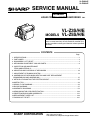
VL-Z3S/H/E
VL-Z5S/H/E
SERVICE MANUAL
S72M7VL-MC500
1st Edition
LIQUID CRYSTAL DIGITAL CAMCORDER
MODELS
PAL
VL-Z3S/H/E
VL-Z5S/H/E
In the interests of user-safety (Required by safety regulations in some countries) the set should be restored to its
original condition and only parts identical to those specified
be used.
CONTENTS
Page
1. SPECIFICATIONS .............................................................................................................................. 2
2. PART NAMES .................................................................................................................................... 3
3. DISASSEMBLY OF THE SET ............................................................................................................ 4
4. MECHANISM ADJUSTMENT JIGS AND PARTS .............................................................................. 8
5. INSPECTION AND MAINTENANCE
ITEMS AND INTERVALS ................................................................................................................... 9
6. ADJUSTING AND CHECKING OF MECHANISM ........................................................................... 10
7. ADJUSTMENT OF RUNNING SYSTEM .......................................................................................... 13
8. ASSEMBLING OF MECHANISM SECTION AND PART REPLACEMENT
(DISASSEMBLING AND ASSEMBLING) ........................................................................................... 15
9. METHOD OF ADJUSTING THE ELECTRIC CIRCUIT .................................................................... 25
10.USEFUL TIPS ................................................................................................................................... 43
11.SIGNAL FLOW DIAGRAMS ............................................................................................................. 44
12.BLOCK DIAGRAMS ......................................................................................................................... 47
13.SCHEMATIC DIAGRAMS ................................................................................................................ 54
14.SEMICONDUCTOR LEAD IDENTIFICATION ............................................................................... 120
15.PRINTED WIRING BOARD ASSEMBLIES .................................................................................... 122
16.REPLACEMENT PARTS LIST ....................................................................................................... 139
17.PACKING OF THE SET ................................................................................................................. 161
SHARP CORPORATION
This document has been published to be used for
after sales service only.
The contents are subject to change without notice.
1
VL-Z3S/H/E
VL-Z5S/H/E
1. SPECIFICATIONS
Signal System:
Recording System:
Cassette:
Recording/Playback Time:
Tape Speed:
Pickup Device:
Lens:
Lens Filter Diameter:
Monitor:
Built-in Microphone:
Color Temperature Compensation:
Minimum Illumination:
Still Image Compression System:
Still Image Recording Format:
Still Image Recording Medium:
Power Requirement:
Power Consumption:
Operating Temperature:
Operating Humidity:
Storage Temperature:
Dimensions (approx.):
Weight (approx.):
PAL standard
2 rotary heads, helical scanning system
Digital VCR Mini DV video cassette
90 minutes (DVM60, LP mode)
SP mode: 18.831 mm/second
LP mode: 12.568 mm/second
1/ " (6.4 mm, effective size: 4.5 mm) CCD image sensor
4
(with approx. 800,000 pixels including optical black,
effective pixels: approx. 414,000 pixels)
10 × optical zoom lens (F1.8, f=3.8-38.0 mm)
30 mm
2.5" (6.4 cm) CGSilicon
Electret stereo microphone
Auto white balance with white balance lock
2 lux* (with gain-up, F1.8)
JPEG base line conformance
JPEG (Exif2.2)
SD Memory Card, MultiMediaCard
DC 7.4 V
3.6 W (during camera recording in Tape Camera mode using the viewfinder in Full
Auto mode with the DIS function on)
4.2 W (during camera recording in Tape Camera mode using the LCD monitor in
Full Auto mode with the DIS function on and backlight in normal mode)
0°C to +40°C
30% to 80%
–20°C to +60°C
82.8 mm (W) × 82.2mm (H) × 101.5 mm (D)
VL-Z5: 485 g
VL-Z3: 478 g
(without battery pack, lithium battery, video cassette, lens cap and card)
AC Adapter (UADP-A016WJZZ)
Power Requirement:
DC Output:
Dimensions (approx.):
Weight (approx.):
AC 110-240 V, 50/60 Hz
10 V
49.0mm (W) × 27.5mm (H) × 79.0 mm (D)
125 g
Specifications are subject to change without notice.
*Minimum illumination: Since there is no widely accepted testing procedure for determining minimum illumination
capability, lux ratings are comparable only between models from the same manufacturer.
2
VL-Z3S/H/E
VL-Z5S/H/E
2. PART NAMES
Front view
Operation button
Zoom lens
DISPLAY button
LCD LAMP button
Stereo microphone
Right view
Left view
USB terminal
Power Zoom Wide angle/
Telephoto control/
PHOTO button VOLume control
Window cleaning cover
Earphones jack
(VL-Z5 only)
Viewfinder
Media Selection
switch ( Tape
mode/ Card
mode selection
switch)
STANDBY indicator
STANDBY button
POWER/CHARGE
(RED) indicator
LCD monitor
Speaker
DC IN jack
DC IN jack cover
AV terminal
Start/Stop button
Terminal cover
DV terminal
Hand strap
Power switch ( Camera
Recording mode/
Playback
mode select switch)
Cassette holder
Lithium battery cover
Cassette compartment
door release
Diopter adjustment dial
Tripod socket*
Battery release
* When attaching a tripod
with a guide pin, do not
attach the pin to the bottom
of the camcorder.
Cassette compartment door
Card slot cover
3
VL-Z3S/H/E
VL-Z5S/H/E
3. DISASSEMBLY OF THE SET
3-1. Procedure for disassembling the cabinet
Note:
Before removing the cabinet, turn OFF the power and make sure that the battery is not connected.
1.
· Remove the lens hood and remove the screw ((s) XiPSF14P06000).
· Open the LCD panel 90 degrees and remove the two screws ((x)LXHZ0050TAFN).
· Remove the two screws ((c)XiPSN17P04000) and remove the KS
camera front cover by pulling it frontward.
LCD panel
x
x
s
c
Lens hood
c
KS camera front cover
2.
· Disconnect the connector of the KS camera front cover.
· Disconnect the two LCD tilt FPCs of the liquid crystal panel.
· Remove the two screws ((r) XiPSN20P08000) and remove the LCD
panel.
· Remove the screw ((p) LX-HZ0063TAFN) and screw ((q)
XiPSN17P06000) that hold the camera L cabinet, open the terminal
cover and remove the three screws ((b) XiPSN17P03000).
r
r
LCD panel
q
p
Camera L cabinet
b
Terminal cover
b
LCD tilt FPC
b
Connector
KS camera front cover
3.
· Disconnect the hot shoe FPC of the hot shoe and remove the
camera L cabinet.
· Remove the screw ((c) XiPSN17P04000) and remove the KS
camera bottom cover.
· Remove the two screws ((a) XiPSN17P02000) and remove the LCD
tilt reinforcing fitting.
Camera L cabinet
Hot shoe FPC
a
a
KS camera bottom cover
LCD tilt reinforcing fitting
4
c
VL-Z3S/H/E
VL-Z5S/H/E
6.
4.
b
b
Mechanism reversion detection PWB unit
x
VF
Camera top cover
u
u
u
Connector
Camera unit
b
PWB mounting angle
p
FPC(3)
a
FPC(2)
FPC(1)
· Remove the screw ((x) LX-HZ0050TAFN), screw ((p) LXHZ0063TAFN) and screw ((a) XiPSN17P02000), disconnect
the FPC (1) and remove the camera top cover.
· Remove the screw ((b) XiPSN17P03000) from the camera
unit, disconnect the FPC (2) and remove the camera unit.
· Remove the screw ((b) XiPSN17P03000), disconnect the
connector and FPC (3) and remove the VF.
5.
· Remove the screw ((b) XiPSN17P03000) and remove the
Mechanism reversion detection PWB unit.
· Remove the three screws ((u) LX-BZ0221TAFC) and remove
the PWB mounting angle.
7.
x
Sub PWB unit
Radiating angle
b
b
LCD tilt unit assembly
b
b
Terminal cabinet
b
a
Main PWB unit
b
x
· Turn the LCD tilt unit assembly 90 degrees.
· Remove the three screws ((b) XiPSN17P03000).
· Remove the screw ((a) XiPSN17P02000).
PWB mounting angle
x
Connector
Tilt FPC
· Disconnect the two connectors of the sub PWB unit and main
PWB unit.
· Remove the two screws ((b) XiPSN17P03000) from the
radiating angle, remove the screw ((b) XiPSN17P03000)
from the PWB unit and remove each unit.
· Disconnect the two FFCs of the main PWB unit.
· Remove the two screws ((x) LX-HZ0050TAFN), remove the
screw ((x) LX-HZ0050TAFN) form the PWB mounting angle
and remove the terminal cabinet.
5
VL-Z3S/H/E
VL-Z5S/H/E
3-2. Procedure for disassembling the cabinet
1.
· Remove the three screws ((e) XiPSF17P03000) , remove the screw
((d) XiPSF17P02000) and remove the VTR bottom cover.
e
e
d
VTR bottom cover
e
2.
· Remove the two screws ((e) XiPSF17P03000) and remove the tilt
cover.
· Remove the VTR front cover with the cassette cover opened.
· Disconnect the connector and two tilt FPCs, remove the three screws
((h) LX-BZ0220TAFC) and remove the KS camera tilt.
e
e
Tilt cover
h
h
h
How to remove the VTR front cover
1. Remove the two couplings and turn the VTR front cover about 20 degrees in
the direction indicated by (1).
2. Turn the VTR front while sliding it in the direction indicated by (2) to disengage
the internal lug.
* If the VTR front cover is removed by turning it forcedly in the direction indicated
by (1), the internal lug may be damaged.
KS camera unit
1
Tilt FPC
Connector
If the VTR front cover is removed
only by turning it in the direction
indicated
The internal lug
may be damaged
VTR front cover
2
3.
· Remove the screw ((f) XiPSF17P04000) with the cassette lid opened,
disconnect the operation PWB FFC and remove the KS VTR operating
cover.
KS VTR operating cover
f
Operating PWB FFC
6
VL-Z3S/H/E
VL-Z5S/H/E
4.
· Disconnect the six FPCs of the head amp circuit board
unit.
· Remove the two screws ((a) XiPSN17P02000) and
remove the head amp PWB unit.
· Remove the three screws ((w) LX-BZA022WJFN) and
remove the screw ((k) LX-BZA023WJFD).
· Remove the mechanism with the cassette lid opened.
Mechanism
w
w
k
w
a
FPC
Head amp PWB unit
5.
a
x
· Remove the screw ((x) LX-HZ0050TAFN).
· Remove the two screws ((d) XiPSF17P02000) and remove the cassette
lid.
Cassette lid
d
d
6.
KS upper lid cover
· Remove the two screws ((d) XiPSF17P02000).
· Disconnect the connector of the speaker while removing the KS upper
lid cover with the cassette control lid opened.
· Remove the screw ((d) XiPSF17P02000) and remove the lock support
cover.
· Remove the speaker.
d
Lock support cover
d
d
Connector
Speaker
7