Download REMOVAL, INSTALLATION AND ADJUSTMENT
Transcript
INDEX
REMOVAL, INSTALLATION AND ADJUSTMENTS
SERVICE MANUAL NUMBER 14
REMOVAL, INSTALLATION AND ADJUSTMENT
Section 2A - All Models
Table of Contents
Sterndrive Unit Removal . . . . . . . . . . . . .
Sterndrive Unit Installation . . . . . . . . . . . .
Remote Control Shift Cable
Adjustment (Drive Unit Installed) . . . . . .
Troubleshooting Shift Problems . . . . .
Propeller Installation . . . . . . . . . . . . . .
Transom Assembly Removal . . . . . . . . .
Power Steering Models . . . . . . . . . . . .
Manual Steering Models . . . . . . . . . . .
Transom Assembly Installation . . . . . . . .
Power Steering Models . . . . . . . . . . . .
Manual Steering Models . . . . . . . . . . .
90-818177--3 APRIL 2001
2
A
2A-2
2A-6
2A-13
2A-22
2A-23
2A-25
2A-25
2A-26
2A-31
2A-36
2A-38
Page 2A-1
INDEX
REMOVAL, INSTALLATION AND ADJUSTMENTS
SERVICE MANUAL NUMBER 14
Sterndrive Unit Removal
1. Move remote control shift lever into the FORWARD gear position on standard rotation
gear cases, or REVERSE on counter rotation gear cases.
2. Press trailer button on control handle to raise drive unit to trailer position / full-up position.
3. Raise the drive unit to gain access to area between gimbal housing and sterndrive
immediately atop the transom end of the anti-ventilation plate.
4. Disconnect speedometer fittings following a. or b. as appropriate:
a. Grasp the top half of the plastic fitting, turn counterclockwise and pull up to
disengage locking device.
a
a
c
c
b
b
75580
70025
1997-1/2 and Earlier Model Speedometer Connector
a - Speedometer Connector, Male End
b - Speedometer Connector, Female End
c - Alignment Slots
Page 2A-2
90-818177--3 APRIL 2001
INDEX
REMOVAL, INSTALLATION AND ADJUSTMENTS
SERVICE MANUAL NUMBER 14
b. Push in on the release button on the female end of the speedometer connector. Pull
to remove.
a
d
b
75502
c
a
75581
a
f
e
75513
1998 and Later Model Speedometer Connector
a - Speedometer Connector, Female End
b - Bell Housing
c - Sta-Strap
d - Release Button
e - Speedometer Connector, Male End
f - Drive Unit
IMPORTANT: When lifting drive with other than hydraulic system, secure the drive
unit with a suitable lifting device so that the drive unit will not fall.
5. Lower drive unit to full IN/DOWN position.
90-818177--3 APRIL 2001
Page 2A-3
INDEX
REMOVAL, INSTALLATION AND ADJUSTMENTS
SERVICE MANUAL NUMBER 14
6. Remove power trim cylinders (aft end) from drive unit.
c
b
a
d
e
70027
a
b
c
d
e
- Aft Anchor Pin
- Bushings (4)
- Flat Washers (2)
- E-ring Clips (2)
- Plastic Caps (2)
a
b
b
70026
a - Aft Anchor Pin
b - Bushings
Page 2A-4
90-818177--3 APRIL 2001
INDEX
REMOVAL, INSTALLATION AND ADJUSTMENTS
SERVICE MANUAL NUMBER 14
7. Remove the 6 locknuts and 5 washers that hold the drive unit to the transom unit and
remove sterndrive unit.
b
b
a
c
22062
a - Locknuts (6)
b - Washers (5)
c - Ground Plate
8. Remove bell housing gasket.
a
70085
a - Bell Housing Gasket
90-818177--3 APRIL 2001
Page 2A-5
INDEX
REMOVAL, INSTALLATION AND ADJUSTMENTS
SERVICE MANUAL NUMBER 14
Sterndrive Unit Installation
1. Install and align engine. Refer to appropriate engine service manual.
IMPORTANT: Rubber gasket must be properly positioned and glued in bell housing
bore before installing drive unit or water may leak into boat.
2. Ensure that rubber gasket and water passage O-ring are properly positioned in bell
housing.
3. Coat entire stud and threads with 2-4-C Marine Lubricant with Teflon.
c
a
b
70022
a - Rubber Gasket
b - Water Passage O-ring
c - Studs
4. Coat drive unit pilot, U-joint shaft O-rings and U-joint shaft splines with Engine
Coupler Spline Grease.
a
b
c
70114
a - Drive Unit Pilot
b - U-joint Shaft O-rings
c - U-joint Shaft Splines
5. Snap the Shift Slide Stabilizer Tool onto stud directly below shift slide and position as
shown.
Page 2A-6
90-818177--3 APRIL 2001
INDEX
REMOVAL, INSTALLATION AND ADJUSTMENTS
SERVICE MANUAL NUMBER 14
6. Position bell housing shift slide so that slot in intermediate shaft coupler is positioned
straight fore and aft. Do this by placing remote control shift lever in: FORWARD gear
WOT position for RH drive or REVERSE gear position for LH drive unit.
75684
a
a
75199
b
75198
a - Shift Shaft Slide Stabilizer Tool
b - Shift Slide
IMPORTANT: Shift slide assembly is free to rotate on core wire. Therefore, be careful
that shift slide remains in upright position and is properly engaged with shift shaft
lever while installing drive unit.
7. Position drive unit shift shaft so that is straight forward by turning shift shaft clockwise
while simultaneously turning propeller shaft counterclockwise.
a
70033
a - Drive Unit Shift Shaft Coupler
IMPORTANT: Be sure to install RH or LH drive unit on the appropriate transom
assembly when making dual engine installations. The LH rotation drive unit can be
identified by the decal on the back side of the upper drive shaft housing, which
states: “Alpha One - Counter Rotation” or has an L on the propshaft
90-818177--3 APRIL 2001
Page 2A-7
INDEX
REMOVAL, INSTALLATION AND ADJUSTMENTS
SERVICE MANUAL NUMBER 14
8. Place gasket on bell housing.
a
70048
Without Gear Lube Monitor
(Shown Without Shift Slide Stabilizer Tool For Visual Clarity)
a - Gasket
NOTE: If equipped with Gear Lube Monitor BE SURE to install the gasket with the hole for
oil passage.
a
b
70048
With Gear Lube Monitor
(Shown Without Shift Slide Stabilizer Tool For Visual Clarity)
a - Gasket
b - Oil Passage Hole
9. Install sterndrive unit:
a. Position trim cylinder straight back (over top of acceleration plate). Be careful not to
scratch acceleration plate or trim cylinders.
b. Guide U-joint shaft through gimbal bearing and into engine coupler while
simultaneously guiding shift slide into drive shaft housing. Make sure shift slide
remains upright and engaged with bell housing shift shaft lever.
c. After the U-joint shaft has begun to enter the engine coupler, remove the Shift Slide
Stabilizer Tool.
Page 2A-8
90-818177--3 APRIL 2001
INDEX
REMOVAL, INSTALLATION AND ADJUSTMENTS
SERVICE MANUAL NUMBER 14
d. Ensure that the stud is thoroughly coated with Quicksilver 2-4-C Marine Lubricant
with Teflon.
IMPORTANT: If drive unit will not slide all the way into bell housing, ensure shift shaft
couplers are positioned properly and all O-rings are greased. Do not force drive unit
into position.
e. If necessary, rotate propeller shaft counterclockwise slightly to help align U-joint
shaft splines with engine coupler splines. Then slide drive unit into bell housing.
10. Secure drive unit to bell housings using fasteners as shown. Torque to 50 lb-ft (68 NSm).
a
b
22062
a - Locknut and Flat Washers
b - Locknut and Continuity Circuit Washer (No Flat Washer at this Location)
11. Return remote control shift lever to the neutral position.
12. Install trim cylinders on aft end of drive unit with hardware as shown. Coat all
components, except plastic caps, with Quicksilver Special Lube 101 upon installation.
Push-fit plastic caps onto ends of aft anchor pins.
a. Insert one bushing in each inboard hole of both trim cylinders.
b. Align the bores of the trim cylinders with that of the drive unit.
c. Insert the aft anchor pin through one of the trim cylinders, the drive unit bore and then
the other trim cylinder until it protrudes equally on both sides of the unit.
90-818177--3 APRIL 2001
Page 2A-9
INDEX
REMOVAL, INSTALLATION AND ADJUSTMENTS
SERVICE MANUAL NUMBER 14
NOTE: Distance between the trim cylinders and the drive unit anchor pin bore is
exaggerated for visual clarity.
a
b
b
70026
a - Aft Anchor Pin
b - Bushings
d. Install the two remaining bushings onto the aft anchor pin ends and fit into bore of
trim cylinders.
e. Install the flat washers.
f.
Install the E-ring clips.
NOTE: The inboard grooves of the aft anchor pin are for E-ring clips, and wider, outboard
grooves are for securing plastic caps.
e
c
a
b
d
70027
a
b
c
d
e
- Aft Anchor Pin
- Bushings
- Flat Washers (2)
- E-ring Clips (2)
- Plastic Caps (2)
13. Raise drive to gain access to area between gimbal housing and sterndrive, immediately
atop the transom end of the anti-ventilation plate.
14. Connect speedometer fittings following a. or b. as appropriate:
Page 2A-10
90-818177--3 APRIL 2001
INDEX
REMOVAL, INSTALLATION AND ADJUSTMENTS
SERVICE MANUAL NUMBER 14
a. Align the plastic fittings, push down and turn clockwise to engage locking device.
a
a
c
b
c
b
70025
75580
1997-1/2 and Earlier Model Speedometer Connector
a - Male End Of Speedometer Fitting
b - Female End Of Speedometer Fitting
c - Alignment Slots
90-818177--3 APRIL 2001
Page 2A-11
INDEX
REMOVAL, INSTALLATION AND ADJUSTMENTS
SERVICE MANUAL NUMBER 14
b. Push the release button and slide the female portion of the speedometer connector
over the male portion.
b
c
a
75581
a - Speedometer Connector, Female End
b - Bell Housing
c - Sta-Strap
b
c
a
75513
1998 and Later Model Speedometer Connector
a - Speedometer Connector, Male End
b - Speedometer Connector, Female End
c - Gear Housing
Page 2A-12
90-818177--3 APRIL 2001
INDEX
REMOVAL, INSTALLATION AND ADJUSTMENTS
SERVICE MANUAL NUMBER 14
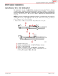
Remote Control Shift Cable Adjustment (Drive Unit Installed)
NOTE: The illustrations on the following pages show models that have a shift plate that is
mounted on the exhaust elbow. The shift mechanism components on the 3.0L model are
located on the top of the valve cover or on the starboard harness bracket. The procedure
for making the adjustments is the same.
IMPORTANT: Shift cable adjustment for a right hand (RH) rotation drive unit is different than the procedure for adjusting a left hand (LH) rotation drive unit. Be sure to
refer to the appropriate procedure when performing the following steps.
IMPORTANT: Drive unit must be installed.
IMPORTANT: DO NOT run engine.
1. Remove remote control shift cable and shift assist assembly (if installed).
a
b
50308
With Shift Assist Assembly
a - Shift Assist Assembly
b - Remote Control Shift Cable
a
50310
Without Shift Assist Assembly
a - Remote Control Shift Cable
90-818177--3 APRIL 2001
Page 2A-13
INDEX
REMOVAL, INSTALLATION AND ADJUSTMENTS
SERVICE MANUAL NUMBER 14
2. Ensure shift lever adjustable stud is located in the slot at the end closest to the shift lever
pivot point. If necessary, loosen stud and align stud in the slot, then retighten stud.
50309
a
a - Adjustable Stud
3. Shift remote control as stated in a. or b.:
a. Right Hand (RH) Rotation Drive Unit - forward gear, past detent, into wide-openthrottle position.
b. Left Hand (LH) Rotation Drive Unit - reverse gear, past detent, into
wide-open-throttle position.
F
(RH)
N
R
R
(LH)
4. Place drive unit into gear by pushing in on drive unit shift cable, while simultaneously
rotating propeller shaft counterclockwise until shaft stops, to ensure full clutch engagement. Maintain a light pressure on the drive unit shift cable to hold it at the end of its travel
(this removes all slack from the cable).
Page 2A-14
90-818177--3 APRIL 2001
INDEX
REMOVAL, INSTALLATION AND ADJUSTMENTS
SERVICE MANUAL NUMBER 14
IMPORTANT: Do not use excessive force when holding pressure on the drive unit
shift cable. Excessive force would be indicated by movement of the V-notch of the
actuator lever assembly.
a
b
22266
a - Drive Unit Shift Cable - Push In
b - Propeller Shaft - Rotate Counterclockwise
5. Lightly pull on remote control shift cable end guide (to remove slack from remote control
and cable) and adjust brass barrel as necessary to align attaching points with shift lever
clevis pin hole and stud. Be sure to maintain light pressure on drive unit shift cable.
c
a
d
b
50309
a
b
c
d
90-818177--3 APRIL 2001
- End Guide
- Brass Barrel
- Shift Lever Clevis Pin Hole
- Stud
Page 2A-15
INDEX
REMOVAL, INSTALLATION AND ADJUSTMENTS
SERVICE MANUAL NUMBER 14
6. After cable has been aligned, turn brass barrel 4 turns away from cable end guide.
b
a
50308
e - End Guide
f - Brass Barrel
7. Temporarily install remote control shift cable on stud and install clevis pin.
50308
a
b
a - Remote Control Shift Cable
b - Clevis Pin
8. Shift remote control as stated in a. or b. :
a. Right Hand (RH) Rotation Drive Unit - reverse gear, past detent, into wide-openthrottle position.
b. Left Hand (LH) Rotation Drive Unit - forward gear, past detent, into wide-openthrottle position.
(LH)
(RH)
R
Page 2A-16
F
N
R
90-818177--3 APRIL 2001
INDEX
REMOVAL, INSTALLATION AND ADJUSTMENTS
SERVICE MANUAL NUMBER 14
9. Simultaneously rotate propeller shaft clockwise until shaft stops to ensure full clutch engagement.
a
22267
a - Propeller Shaft - Rotate Clockwise
10. Perform a. or b. as appropriate:
a. On Models with Earlier Type Switch: check shift cutout switch lever position. Roller must be centered.
a
22058
a - Shift Cutout Switch Roller
b. On Models with Later Type Switch: check shift cutout switch plunger position. Pin
must be centered.
a
75128
a - Shift Cutout Switch Plunger
11. If roller or plunger pin is not centered:
a. Ensure adjustable stud is at bottom of slot in shift lever.
b. Check remote control for proper shift cable output [3 in. (76 mm) ± 1/8 in. (3 mm)].
c. If a and b are correct, ensure drive unit shift cable is not crushed or kinked. (If drive
unit shift cable is binding, the shift cutout switch roller or plunger pin will move off
center when shifting “into” and “out of” forward and reverse).
90-818177--3 APRIL 2001
Page 2A-17
INDEX
REMOVAL, INSTALLATION AND ADJUSTMENTS
SERVICE MANUAL NUMBER 14
NOTE: If shift cable was damaged during installation, install new shift cable assembly, then
repeat shift cable adjustment procedure.
CAUTION
Improper installation of the shift assist assembly could result in damage or malfunction to the shift control box.
For Commander 3000 Controls, if shift assist assembly attaching points do not align, verify
controller is in the neutral position. Remove the shift cable and reposition the adjustment
barrel as required to allow the shift assembly to be installed with no effort.
For ALL other controls, if shift assist assembly attaching points do not align, push in or
pull out on end of shift assist assembly to install. Do not attempt to readjust shift cable.
Page 2A-18
90-818177--3 APRIL 2001
INDEX
REMOVAL, INSTALLATION AND ADJUSTMENTS
SERVICE MANUAL NUMBER 14
12. After remote control shift cable has been properly adjusted, reinstall cable and shift assist assembly (if applicable) and secure with hardware. Tighten locknut completely then
back off 1/2 turn.
d
e
a
f
b
g
c
50308
With Shift Assist Assembly
a - Remote Control Shift Cable
b - Shift Assist Assembly
c - Clevis Pin
d - Cotter Pin
e - Large I.D. Washer
f - Small I.D. Washer
g - Locknut
90-818177--3 APRIL 2001
Page 2A-19
INDEX
REMOVAL, INSTALLATION AND ADJUSTMENTS
SERVICE MANUAL NUMBER 14
c
a
d
b
g
h
e
i
f
50310
Without Shift Assist Assembly
a - Remote Control Shift Cable
b - Clevis Pin
c - Cotter Pin
d - Spring
e - Washer
f - Washer
g - Spacer
h - Washer
i - Locknut
IMPORTANT: If an extra long remote control shift cable is used, or if there are a large
number of bends in remote control shift cable, or remote control has inadequate output travel, an additional adjustment may be necessary. Refer to step 13 or 14 as applicable.
13. Remote Control with Single Lever Shift/Throttle Control:
a. RIGHT HAND (RH) propeller rotation drive unit - Shift remote control into reverse
gear, wide-open-throttle position while simultaneously rotating propeller shaft clockwise. Clutch should engage and cause propeller shaft to lock. If clutch does not engage, loosen adjustable stud on shift lever and move it upward in slot until clutch
engages with reverse gear. Retighten stud. Shift remote control several times and
stop in reverse to recheck shift cutout switch position. Roller or pin must be centered.
b. LEFT HAND (LH) propeller rotation drive unit - Shift remote control into forward
gear, wide-open-throttle position while simultaneously rotating propeller shaft clockwise. Clutch should engage and cause propeller shaft to lock. If clutch does not engage, loosen adjustable stud on shift lever and move it upward in slot until clutch
engages with forward gear. Retighten stud. Shift remote control several times and
stop in forward to recheck shift cutout switch position. Roller or pin must be centered.
14. Two Lever Remote Control with Separate Shift and Throttle Levers:
a. RIGHT HAND (RH) propeller rotation drive unit - While turning propeller shaft
clockwise, move remote control shift handle into full reverse position. Clutch should
engage before shift lever comes to a stop. If clutch does not engage, loosen adjustable stud on shift lever and move it upward in slot until clutch engages with reverse
gear. Retighten stud. Shift remote control several times and stop in reverse to recheck shift cutout switch position. Roller or pinmust be centered.
b. LEFT HAND (LH) propeller rotation drive unit - While turning propeller shaft
clockwise, move remote control shift handle into full forward position. Clutch should
Page 2A-20
90-818177--3 APRIL 2001
INDEX
REMOVAL, INSTALLATION AND ADJUSTMENTS
SERVICE MANUAL NUMBER 14
engage before shift lever comes to a stop. If clutch does not engage, loosen adjustable stud on shift lever and move it upward in slot until clutch engages with forward
gear. Retighten stud. Shift remote control several times and stop in forward to recheck shift cutout switch position. Roller or pin must be centered.
a
50309
a - Adjustable Stud
a
22058
a - Shift Cutout Switch Roller
a
75128
a - Shift Cutout Switch Plunger
90-818177--3 APRIL 2001
Page 2A-21
INDEX
REMOVAL, INSTALLATION AND ADJUSTMENTS
SERVICE MANUAL NUMBER 14
Troubleshooting Shift Problems
NOTE: The following information is provide to assist an installer in troubleshooting if hard
shifting or chucking/racheting is encountered when shifting into FORWARD gear.
1. When installing the control box in the side panel of the boat, make sure that the cables
have enough clearance to operate. This is necessary because the cables move up and
down when the shift handle is moved. If the control box is mounted too far back towards
any fiberglass structure, the cables will be interfered with, this will cause very hard
shifting.
NOTE: The control box housing can be rotated in 30° increments to improve cable routing.
74688
Proper Cable Bend
74689
Improper Cable Bend
2. Ensure that when the shift cable from the control box is led through the side gunnel of
the hull, it does not have any extremely sharp bends in it as this will cause the stiff
shifting.
3. Before installing the shift cable into the control box, extend the stainless rod eye end of
the cable and grease it with 2-4-C Marine Lubricant with Teflon. Move it back and forth
to allow even distribution of the grease.
22005
4. Do not strap or clamp the control cables to any other cables or rigid structure within 3
ft. (914 mm) of the control box.
5. Be sure the cable is not permanently kinked.
6. Make sure there is proper clearance for cable movement when the control box is
installed in the side panel. The cables must have room to move up and down when the
control handle is shifted into either FORWARD or REVERSE.
7. Ensure that the engine was not set down on the intermediate shift cable during
installation, as this will crush the inner cable tubing and cause improper and / or stiff
shifting.
Page 2A-22
90-818177--3 APRIL 2001
INDEX
REMOVAL, INSTALLATION AND ADJUSTMENTS
SERVICE MANUAL NUMBER 14
8. DO NOT fasten the shift cable with straps or clamps to any other cable within 5 ft. (1524
mm) of the shift plate.
9. DO NOT fasten the shift cable to the transom with any type of plastic clips or fasteners
within 5 ft. (1524 mm) of the shift plate.
10. DO NOT overtighten the throttle or shift cable attaching nuts at the engine end. Barrel
and cable end must be free to rotate on the mounting stud.
11. Check the intermediate shift cable routing from the transom assembly to the shift plate
as follows:
a. The cable should come through the transom, above the exhaust pipe and make a
turn towards the starboard side of the boat between the exhaust pipe and the engine
flywheel housing.
b. The cable should then be routed under the starboard rear engine mount, and turn
towards the transom.
c. Then go up behind the power steering valve and loop over to the shift plate on the
engine, where it is connected to the anchor points on the shift plate.
Following this routing will prevent the engine coupler from damaging the cable.
74903
74901
4 Cylinder Inline Model
V6 and V8 Models
Propeller Installation
WARNING
Be sure that remote control is in the neutral position and ignition key is removed
from switch.
WARNING
Place a block of wood between the antiventilation plate to protect hands from propeller blades and to prevent propeller from turning.
1. To aid in future propeller removal, liberally coat the propeller shaft splines with one of
the following lubricants; then, install propeller.
•
Special Lubricant 101
•
2-4-C Marine Lubricant with Teflon
•
Perfect Seal
90-818177--3 APRIL 2001
Page 2A-23
INDEX
REMOVAL, INSTALLATION AND ADJUSTMENTS
SERVICE MANUAL NUMBER 14
IMPORTANT: Installation is correct when at least 2 threads of propeller shaft are
exposed through propeller nut.
e
f
a
b
d
c
g
22074
Propeller Without Flo-Torq II Drive Hub
a - Propeller Shaft
b - Forward Thrust Hub
c - Propeller
d - Continuity Washer
e - Spline Washer
f - Tab Washer
g - Propeller Nut
a
b
c
d
e
f
70134
Propeller With Flo-Torq II Drive Hub
a - Propeller Shaft
b - Forward Thrust Hub
c - Flo Torq II Drive Hub
d - Propeller
e - Drive Sleeve Adapter and Locking Tab Washer
f - Propeller Nut
2. Torque propeller nut until 55 lb-ft (75 NSm) is obtained and continue until 3 tabs on tab
washer align with grooves on drive sleeve.
3. Bend tabs into drive sleeve.
Page 2A-24
90-818177--3 APRIL 2001
INDEX
REMOVAL, INSTALLATION AND ADJUSTMENTS
SERVICE MANUAL NUMBER 14
Transom Assembly Removal
Power Steering Models
NOTE: If Tie Bars need to be removed or serviced see section 6A or 6B.
1. Remove the power steering assembly..
a. Disconnect clevis from steering lever.
b. Disconnect steering cable from clevis.
d
b
i
g
b
a
c
c
g
a
h
e
d
f
f
22023
71901
Earlier Model Control Valve . . . . . . . . . . . Later Model Control Valve
a - Cable End
b - Clevis
c - Cotter Pin
d - Clevis Pin
e - Locking Plate
f - Cable Retaining Nut
g - Steering Lever
h - Cotter Pin
i - Clevis Pin
90-818177--3 APRIL 2001
Page 2A-25
INDEX
REMOVAL, INSTALLATION AND ADJUSTMENTS
SERVICE MANUAL NUMBER 14
c. Bend tabs away from pivot bolts then loosen bolts and remove power steering unit.
c
b
a
b
c
23256
a - Power Steering Unit
b - Tab Washer
c - Pivot Bolt
Manual Steering Models
1. Remoe the manual steering assembly.
a. Disconnect steering cable or clevis from steering lever.
a
d
c
b
22055
a
b
c
d
Page 2A-26
- Steering Lever
- Steering Cable
- Cotter Pin
- Clevis Pin
90-818177--3 APRIL 2001
INDEX
REMOVAL, INSTALLATION AND ADJUSTMENTS
SERVICE MANUAL NUMBER 14
b. Bend tabs away from pivot bolts. Loosen bolts and remove manual steering swivel
ring.
c
b
a
b
c
22945
a - Swivel Ring
b - Tab Washer
c - Pivot Bolt
2. Disconnect gear lube monitor hose, if equipped. Plug hose and cap fitting.
a
b
a
b
77712
70023
. . . . . . . . . . . . Earlier Style . . . . . . . . . . . . . . . . . . . . . . . . . . Later Style
a - Hose
b - Hose Clamp
3. Disconnect speedometer hose, if equipped.
a
70015
a - Speedometer Fitting
4. Disconnect MerCathode wires from control unit on engine, if equipped.
90-818177--3 APRIL 2001
Page 2A-27
INDEX
REMOVAL, INSTALLATION AND ADJUSTMENTS
SERVICE MANUAL NUMBER 14
5. Disconnect trim limit switch wires at trim pump and trim position sender wires at engine.
6. For engine removal, refer to appropriate engine service manual.
7. Disconnect power trim hydraulic hoses from trim pump. Cap hoses and plug pump fitting
holes.
c
b
a
22031
a - Sta-Strap
b - Trim Limit Switch Wires
c - Hydraulic Hoses
Page 2A-28
90-818177--3 APRIL 2001
INDEX
REMOVAL, INSTALLATION AND ADJUSTMENTS
SERVICE MANUAL NUMBER 14
8. If installed, remove exhaust pipe.
a
70068
b
In-line 4 Cylinder Models
b
a
22057
V6/V8 Models
a - Exhaust Pipe
b - Screws
90-818177--3 APRIL 2001
Page 2A-29
INDEX
REMOVAL, INSTALLATION AND ADJUSTMENTS
SERVICE MANUAL NUMBER 14
9. Remove ground wire from steering lever.
c
b
a
22028
a - Steering Lever
b - Ground Wire
c - Screws
CAUTION
Transom gimbal housing (on outside of boat must be secured prior to the next step
to prevent dropping.
10. Remove all nuts, bolts and washers (items “a” and “h” in diagram) and separate inner
transom plate from transom gimbal housing.
11. Remove transom gimbal housing from transom of boat.
a
f
d
f
a
a
e
c
h
70012
b
a
b
c
d
e
f
g
h
Page 2A-30
g
- Flat Washers and Locknuts
- Hydraulic Hoses
- Drive Unit Shift Cable
- Trim Limit And Trim Position Sender Wires
- Inner Transom Plate
- Ground Wire (Continuity Circuit)
- MerCathode Wires (If Equipped)
- Long Screws, Lock Washers And Square Flat Washers (Later Models - Studs
With Locknuts And Flat Washers)
90-818177--3 APRIL 2001
INDEX
REMOVAL, INSTALLATION AND ADJUSTMENTS
SERVICE MANUAL NUMBER 14
Transom Assembly Installation
CAUTION
On earlier style transom assembly with carriage bolts at the bottom, rubber seal
MUST BE installed on the bolts or water will leak into boat.
a
22028
b
a - Carriage Bolt
b - Rubber Seal
CAUTION
Steering lever ground wire MUST BE positioned as shown or wire may fatigue.
b
c
a
22028
a - Steering Lever
b - Inner Transom Plate
c - Ground Wire
IMPORTANT: Be sure to pull all wires and cables completely through inner transom
plate and ensure wires are not pinched when installing gimbal housing to transom.
IMPORTANT: Torque bolts and nuts evenly (starting from center and working out) to
22.5 lb-ft (30.5 NSm).
90-818177--3 APRIL 2001
Page 2A-31
INDEX
REMOVAL, INSTALLATION AND ADJUSTMENTS
SERVICE MANUAL NUMBER 14
1. Install transom assembly. Tighten attaching bolts and nuts evenly (starting from center
and working out). Torque to 22.5 lb-ft (30.5 NSm).
a
f
d
f
a
a
e
c
h
g
b
a
b
c
d
e
f
g
h
70012
- Flat Washers and Locknuts
- Hydraulic Hoses
- Drive Unit Shift Cable
- Trim Limit And Trim Position Sender Wires
- Inner Transom Plate
- Ground Wire (Continuity Circuit)
- MerCathode Wires (If Equipped)
- Carriage Bolts With Flat Washers And Locknuts (Later Models - Studs, Flat
Washers And Locknuts)
2. If equipped, connect gear lube monitor hose.
a
b
a
b
77712
70023
. . . . . . . . . . . . Earlier Style . . . . . . . . . . . . . . . . . . . . . . . . . . Later Style
a - Hose
b - Hose Clamp
Page 2A-32
90-818177--3 APRIL 2001
INDEX
REMOVAL, INSTALLATION AND ADJUSTMENTS
SERVICE MANUAL NUMBER 14
3. If equipped, connect hose from the speedometer to the barb fitting and secure with cable
tie.
a
70015
a - Barb Fitting
IMPORTANT: Exhaust pipe and gimbal housing mating surfaces must be clean and
free of nicks and scratches or exhaust may leak into boat.
a
b
22057
a - O-ring Seal
b - Mating Surface
4. If equipped, glue O-ring seal to gimbal housing.
90-818177--3 APRIL 2001
Page 2A-33
INDEX
REMOVAL, INSTALLATION AND ADJUSTMENTS
SERVICE MANUAL NUMBER 14
5. Install exhaust pipe or block off plate on gimbal housing. Torque screws to 22.5 lb-ft
(30.5 Nm).
a
70068
b
In-line 4 Cylinder Models
b
a
22057
V6/V8 Models
a - Exhaust Pipe
b - Screws
Page 2A-34
90-818177--3 APRIL 2001
INDEX
REMOVAL, INSTALLATION AND ADJUSTMENTS
SERVICE MANUAL NUMBER 14
6. If using through-transom exhaust, install block off plate and O-ring seal. Torque to
22.5 lb-ft (30.5 Nm)
b
a
22057
Models with Through The Transom Exhaust
a - Block Off Plate
b - Screws
CAUTION
DO NOT cross thread or overtighten hose fittings when making hydraulic hose connections to power trim pumps.
IMPORTANT: Make hydraulic hose connections as quickly as possible to prevent oil
from leaking out of trim system.
7. Connect power trim pump hydraulic hoses. Torque to 125 lb-in. (14.1 Nm).
b
a
22031
d
a
b
c
d
c
- Black Hose (Up Hose)
- Gray Hose (Down Hose)
- Trim Limit Switch Wires
- Wire Retainer and Sta-Strap
8. Connect trim limit switch wires.
90-818177--3 APRIL 2001
Page 2A-35
INDEX
REMOVAL, INSTALLATION AND ADJUSTMENTS
SERVICE MANUAL NUMBER 14
Power Steering Models
1. Install power steering assembly on inner transom plate.
a. Lubricate power steering unit bushings with Special Lubricant 101.
a
71901
a - Power Steering Unit Bushings
b. Slide power steering unit bushings between transom plate mounting brackets.
Install two pivot bolts and at the same time, slightly move (wiggle) steering unit to
ensure proper pivot bolt engagement into bushings. Ensure washer tangs straddle
ridges on inner transom plate.
c
a
b
b
a
c
22168
a - Pivot Bolts
b - Washer Tangs
c - Ridges
c. Torque pivot bolts to 25 lb-ft (34 Nm). Bend washer tabs against flat on bolt heads.
2. If equipped, connect power steering unit clevis to steering lever as follows:
a. Lubricate clevis pin with Special Lubricant 101.
b. Install clevis pin through clevis and steering lever from top.
Page 2A-36
90-818177--3 APRIL 2001
INDEX
REMOVAL, INSTALLATION AND ADJUSTMENTS
SERVICE MANUAL NUMBER 14
c. Secure clevis pin with cotter pin. Bend both ends of cotter pin.
b
c
d
a
70019
a
b
c
d
- Clevis Pin
- Clevis
- Steering Lever
- Cotter Pin
WARNING
Failure to use a steering cable locking device could cause a loss of steering, which
could cause damage to the boat and/or injury.
All current production Quicksilver Ride Guide steering cables have a self-locking coupler
nut and do not require an external locking device. (Other cable manufacturers also make
cables with a self-locking coupler nut.)
3. Install steering cable.
a. Lubricate steering cable end with a liberal amount of Special Lubricant 101 and
install cable end through guide tube.
b. Later Model Control Valve: Using a suitable wrench, hold the flat surfaces on the
cable guide tube in the vertical position.
a
c
b
73901
Later Model Control Valve
a - Flat (Hold Vertical)
b - Suitable Wrench
c - Guide Tube
c. Both Models: Connect cable end to clevis with clevis pin. Secure clevis pin in clevis
with cotter pin. Bend both ends of cotter pin.
90-818177--3 APRIL 2001
Page 2A-37
INDEX
REMOVAL, INSTALLATION AND ADJUSTMENTS
SERVICE MANUAL NUMBER 14
d. Tighten cable coupler nut. Torque to 35 lb-ft (48 Nm).
NOTE: On later models, manually hold the guide tube while tightening the coupler nut.
e. Earlier Model Control Valve: If required, install locking plate on coupler nut and
secure with screw and washer. Torque to 66 lb-in. (7.5 Nm).
NOTE: Later model control valves DO NOT have a locking plate.
d
b
i
g
b
a
c
c
g
a
h
e
d
f
f
22023
71901
Earlier Model Control Valve . . . . . . . . . . . Later Model Control Valve
a - Cable End
b - Clevis
c - Cotter Pin
d - Clevis Pin
e - Locking Plate
f - Cable Retaining Nut
g - Steering Lever
h - Cotter Pin
i - Clevis Pin
Manual Steering Models
1. Install manual steering assembly on inner transom plate.
a. Lubricate swivel ring bushings with Special Lubricant 101.
a
22946
a - Swivel Ring Bushings
b. Slide manual steering swivel ring and bushings between transom plate mounting
brackets. Install two pivot bolts and at the same time, slightly move (wiggle) swivel
Page 2A-38
90-818177--3 APRIL 2001
INDEX
REMOVAL, INSTALLATION AND ADJUSTMENTS
SERVICE MANUAL NUMBER 14
ring to ensure proper pivot bolt engagement into swivel ring bushings. Ensure
washer tangs straddle ridges on inner transom plate.
c
a
b
b
c
a
22168
a - Pivot Bolts
b - Washer Tangs
c - Ridges
c. Torque pivot bolts to 25 lb-ft (34 Nm). Bend washer tabs against flat on bolt heads.
2. Install steering cable.
a. Lubricate steering cable end with a liberal amount of Special Lubricant 101 and
install cable end through guide tube.
b. Connect steering cable to steering lever and secure with clevis pin and cotter pin.
Spread both ends of cotter pin.
c. Tighten coupler nut. Torque to 35 lb-ft (48 Nm).
g
f
b
a
d
e
c
70373
a
b
c
d
e
f
g
90-818177--3 APRIL 2001
- Steering Cable
- Cable Coupler Nut
- Steering Cable Guide Tube
- Steering Cable End
- Cotter Pin
- Clevis Pin
- Steering Lever
Page 2A-39
INDEX
REMOVAL, INSTALLATION AND ADJUSTMENTS
SERVICE MANUAL NUMBER 14
THIS PAGE IS INTENTIONALLY BLANK
Page 2A-40
90-818177--3 APRIL 2001


