1
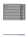
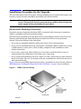
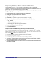
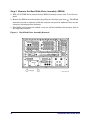
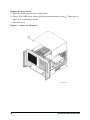
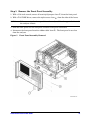
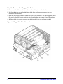
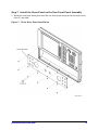
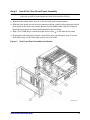
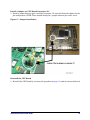
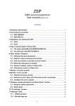
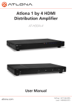
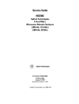
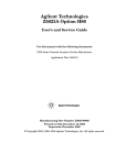
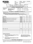
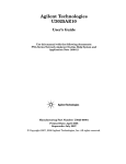
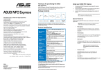
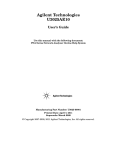
Installation Note
2-Port Front Panel Upgrade Kit
To Upgrade 2-Port PNA “A” and “B” models and PNA-L “A” models to
2-Port PNA and PNA-L “C” models.
Upgrade Kit Order Numbers:
• E8361AU-221 for E8361A PNA
• E8362BU-221 for E8362B PNA
• E8363BU-221 for E8363B PNA
• E8364BU-221 for E8364B PNA
• N5230AU-221 for N5230A 2-Port PNA-L
Agilent Kit Numbers: E8361-60064, E8364-60191, N5230-60046
Agilent Document Number: N5230-90027
Printed in USA October 2010
Supersedes Print Date: March 2010
© Agilent Technologies, Inc. 2008-2010
WARRANTY STATEMENT
THE MATERIAL CONTAINED IN THIS DOCUMENT IS PROVIDED “AS IS,” AND IS SUBJECT TO
BEING CHANGED, WITHOUT NOTICE, IN FUTURE EDITIONS. FURTHER, TO THE MAXIMUM
EXTENT PERMITTED BY APPLICABLE LAW, AGILENT DISCLAIMS ALL WARRANTIES,
EITHER EXPRESS OR IMPLIED WITH REGARD TO THIS MANUAL AND ANY INFORMATION
CONTAINED HEREIN, INCLUDING BUT NOT LIMITED TO THE IMPLIED WARRANTIES OF
MERCHANTABILITY AND FITNESS FOR A PARTICULAR PURPOSE. AGILENT SHALL NOT BE
LIABLE FOR ERRORS OR FOR INCIDENTAL OR CONSEQUENTIAL DAMAGES IN
CONNECTION WITH THE FURNISHING, USE, OR PERFORMANCE OF THIS DOCUMENT OR
ANY INFORMATION CONTAINED HEREIN. SHOULD AGILENT AND THE USER HAVE A
SEPARATE WRITTEN AGREEMENT WITH WARRANTY TERMS COVERING THE MATERIAL IN
THIS DOCUMENT THAT CONFLICT WITH THESE TERMS, THE WARRANTY TERMS IN THE
SEPARATE AGREEMENT WILL CONTROL.
DFARS/Restricted Rights Notice
If software is for use in the performance of a U.S. Government prime contract or subcontract,
Software is delivered and licensed as “Commercial computer software” as defined in DFAR
252.227-7014 (June 1995), or as a “commercial item” as defined in FAR 2.101(a) or as
“Restricted computer software” as defined in FAR 52.227-19 (June 1987) or any equivalent
agency regulation or contract clause. Use, duplication or disclosure of Software is subject to
Agilent Technologies’ standard commercial license terms, and non-DOD Departments and
Agencies of the U.S. Government will receive no greater than Restricted Rights as defined in
FAR 52.227-19(c)(1-2) (June 1987). U.S. Government users will receive no greater than
Limited Rights as defined in FAR 52.227-14 (June 1987) or DFAR 252.227-7015 (b)(2)
(November 1995), as applicable in any technical data.
Safety Notes
The following safety notes are used throughout this document. Familiarize yourself with each
of these notes and its meaning before performing any of the procedures in this document.
WARNING
Warning denotes a hazard. It calls attention to a procedure which,
if not correctly performed or adhered to, could result in injury or
loss of life. Do not proceed beyond a warning note until the
indicated conditions are fully understood and met.
CAUTION
Caution denotes a hazard. It calls attention to a procedure that, if not
correctly performed or adhered to, could result in damage to or destruction
of the instrument. Do not proceed beyond a caution sign until the indicated
conditions are fully understood and met.
2
Installation Note N5230-90027
Downloading the Online PNA Service Guide
To view the online Service Guide for your PNA model number, use the following steps:
1. Go to www.agilent.com.
2. In the Search box, enter the model number of the analyzer (Ex: N5242A) and click Search.
3. Click Technical Support > Manuals.
4. Click Service Manual.
5. Click the service guide title to download the PDF file.
6. When the PDF of the Service Guide is displayed, scroll through the Contents section
bookmarks to locate the information needed.
Getting Assistance from Agilent
By internet, phone, or fax, get assistance with all your test and measurement needs.
Contacting Agilent
Assistance with test and measurements needs and information on finding a local Agilent
office are available on the Web at:
http://www.agilent.com/find/assist
If you do not have access to the Internet, please contact your Agilent field engineer.
NOTE
In any correspondence or telephone conversation, refer to the Agilent product by
its model number and full serial number. With this information, the Agilent
representative can determine whether your product is still within its warranty
period.
Installation Note N5230-90027
3
Description of the Upgrade
This upgrade changes the front panel UI (user interface) of your E8361A, E8362B, E8363B,
E8364B PNA, or N5230A PNA-L to a touchscreen and softkey interface with a new color LCD
display. This is done by removing the existing front panel assembly, removing the internal
floppy disk drive (the new front panel assembly does not allow for a floppy disk drive), and
installing a new front panel assembly.
This upgrade requires that the PNA is using the 1.1 GHz CPU. This CPU is not included in
this kit. Please contact Agilent if you need to replace the CPU.
After installation of this upgrade, your analyzer will be a “C” model rather than an “A” or “B”
model.
IMPORTANT
Included in the contents of this kit is an Option Entitlement Certificate
with instructions on how to redeem it. Do NOT attempt to redeem this
certificate until you have read “Step 13. Obtain a License Key” on page 22.
About Installing the Upgrade
Products affected. . . . . . . . . . . . . . . . . . . . . . . . . . E8361A, E8362B, E8363B, E8364B, and
2-port N5230A
Installation to be performed by . . . . . . . . . . . . . . Agilent service center or personnel
qualified by Agilent
Estimated installation time . . . . . . . . . . . . . . . . . 4.0 hours
Estimated adjustment time . . . . . . . . . . . . . . . . . 0.5 hours
Estimated full instrument calibration time . . . . 4.5 hours
4
Installation Note N5230-90027
Items Included in the Upgrade Kits
Check the contents of your kit against whichever one of the following lists is appropriate. If
any part is missing or damaged, contact Agilent Technologies. Refer to “Getting Assistance
from Agilent” on page 3.
Table 1
Contents of Upgrade Kit E8361-60064 (For E8361A)
Description
Qty
Part Number
Installation note (this document)
1
N5230-90027
Entitlement certificate
1
5964-5145
ROHS addendum
1
9320-6722
Front panel assembly
1
N5230-60044
Front dress panel
1
N5230-00016
Machine screw, 90-deg flat head, M3 x 4 mm (to attach front dress panel)
10
0515-4791
Hard disk drive assembly (HDDA), imaged, for 1.1 GHz CPU (for new front panel assembly)
1
N8982A
Floppy disk containing upgrade installation program for the CPU board
1
N5230-10001
Nameplate: E8361C 10 MHz - 67 GHz
1
E8361-80006
Lower front panel overlay; no options
1
E8361-80002
Lower front panel overlay; any option combination that includes Option 014
1
E8361-80004
Jumper (for CPU board connector)
1
1258-0209
Table 2
Contents of Upgrade Kit E8364-60191 (For E8362B, E8363B, and E8364B)
Description
Qty
Part Number
Installation note (this document)
1
N5230-90027
Entitlement certificate
1
5964-5145
ROHS addendum
1
9320-6722
Front panel assembly
1
N5230-60044
Front dress panel
1
N5230-00016
Machine screw, 90-deg flat head, M3 x 4 mm (to attach front dress panel)
10
0515-4791
Hard disk drive assembly (HDDA), imaged, for 1.1 GHz CPU (for new front panel assembly)
1
N8982A
Floppy disk containing upgrade installation program for the CPU board
1
N5230-10001
Nameplate: E8362C 10 MHz - 20 GHz
1
E8362-80004
Nameplate: E8363C 10 MHz - 40 GHz
1
E8363-80003
Nameplate: E8364C 10 MHz - 50 GHz
1
E8364-80046
Lower front panel overlay; no options, Option UNL, or Option UNL/016
1
E8364-80002
Lower front panel overlay; Option 014, 014/080, or 014/080/081
1
E8364-80003
Lower front panel overlay; Option UNL/014, UNL/014/080/081, or UNL/014/080/081/H11
1
E8364-80011
Lower front panel overlay; Option UNL/014/016, UNL/014/016/080,
UNL/014/016/080/081, or UNL/014/016/080/081/H11
1
E8364-80024
Jumper (for CPU board connector)
1
1258-0209
Installation Note N5230-90027
5
Table 3
Contents of Upgrade Kit N5230-60046 (For 2-port N5230A)
Description
Qty
Part Number
Installation note (this document)
1
N5230-90027
Entitlement certificate
1
5964-5145
ROHS addendum
1
9320-6722
Front panel assembly
1
N5230-60044
Front dress panel
1
N5230-00016
Machine screw, 90-deg flat head, M3 x 4 mm (to attach front dress panel)
10
0515-4791
Hard disk drive assembly (HDDA), imaged, for 1.1 GHz CPU (for new front panel assembly)
1
N8982A
Floppy disk containing upgrade installation program for the CPU board
1
N5230-10001
Nameplate: N5230C 300 kHz - 6 GHz (For Option 020 or 025.)
1
N5230-80019
Nameplate: N5230C 300 kHz - 13.5 GHz (For Option 120 or 125.)
1
N5230-80020
Nameplate: N5230C 10 MHz - 20 GHz (For Option 220 or 225.)
1
N5230-80022
Nameplate: N5230C 10 MHz - 40 GHz (For Option 420 or 425.)
1
N5230-80023
Nameplate: N5230C 10 MHz - 50 GHz (For Option 520 or 525.)
1
N5230-80024
Lower front panel overlay; Option 020 or 120
1
N5240-80001
Lower front panel overlay; Option 025 or 125
1
N5240-80002
Lower front panel overlay; Option 220
1
N5230-80017
Lower front panel overlay; Option 225, 425, or 525
1
N5230-80005
Lower front panel overlay; Option 420 or 520
1
E8364-80002
Jumper (for CPU board connector)
1
1258-0209
6
Installation Note N5230-90027
Installation Procedure for the Upgrade
The network analyzer must be in proper working condition prior to installing this option. Any
necessary repairs must be made before proceeding with this installation.
WARNING
This installation requires the removal of the analyzer’s protective outer
covers. The analyzer must be powered down and disconnected from the
mains supply before performing this procedure.
Electrostatic Discharge Protection
Protection against electrostatic discharge (ESD) is essential while removing or connecting
cables or assemblies within the network analyzer.
Static electricity can build up on your body and can easily damage sensitive internal circuit
elements when discharged. Static discharges too small to be felt can cause permanent
damage. To prevent damage to the instrument:
• always have a grounded, conductive table mat in front of your test equipment.
• always wear a grounded wrist strap, connected to a grounded conductive table mat, having
a 1 MΩ resistor in series with it, when handling components and assemblies or when
making connections.
• always wear a heel strap when working in an area with a conductive floor. If you are
uncertain about the conductivity of your floor, wear a heel strap.
• always ground yourself before you clean, inspect, or make a connection to a static-sensitive
device or test port. You can, for example, grasp the grounded outer shell of the test port or
cable connector briefly.
Figure 1 shows a typical ESD protection setup using a grounded mat and wrist strap. Refer to
“ESD Equipment and Supplies Required for the Installation” on page 8 for part numbers.
Figure 1
ESD Protection Setup
Installation Note N5230-90027
7
Tools Required for the Installation
Description
Agilent Part Number
T-10 TORX driver (set to 9 in-lbs)
N/A
T-20 TORX driver (set to 21 in-lbs)
N/A
5/16-inch torque wrench (set to 10 in-lbs)
N/A
ESD Equipment and Supplies Required for the Installation
Description
Agilent Part Number
ESD grounding wrist strap
9300-1367
5-ft grounding cord for wrist strap
9300-0980
2 x 4 ft conductive table mat and 15-ft grounding wire
9300-0797
ESD heel strap (for use with conductive floors)
9300-1308
Overview of the Installation Procedure
Step 1. Copy All Unique Files to an External Disk Drive.
Step 2. Flash the BIOS Using the Floppy Disk Provided.
Step 3. Remove the Hard Disk Drive Assembly (HDDA).
Step 4. Remove the Outer and Inner Covers.
Step 5. Remove the Front Panel Assembly.
Step 6. Remove the Floppy Disk Drive.
Step 7. Install the Dress Panel on the New Front Panel Assembly.
Step 8. Install the New Overlays on the New Front Panel Assembly.
Step 9. Install the New Front Panel Assembly.
Step 10. Modify the CPU Board.
Step 11. Install the New Hard Disk Drive Assembly (HDDA).
Step 12. Reinstall the Inner and Outer Covers.
Step 13. Obtain a License Key.
Step 14. Change Model Number.
Step 15. Copy the Unique Files Back to the Analyzer’s HDD.
Step 16. Perform Post-Upgrade Adjustments and Calibration.
8
Installation Note N5230-90027
Step 1. Copy All Unique Files to an External Disk Drive
The hard disk drive (HDD) in your analyzer will be replaced as part of this upgrade.
Therefore, it is necessary that all unique and personal files stored on the HDD be saved to an
external disk drive for reinstallation later on the new HDD.
This procedure is written assuming a USB flash memory drive is used, although any external
disk drive will suffice.
1. Connect the power cord to the analyzer and turn ON the power.
2. Insert a USB flash memory drive into a USB port.
3. Open Windows Explorer.
4. Navigate to C:\Program Files\Agilent\Network Analyzer.
5. Copy each of the following files from the hard disk drive to the USB drive:
• user_calkitfile
• All files prefixed with mxcalfile_.
• Any personal user files that you wish to preserve.
6. Remove the USB drive from the USB port.
7. Exit Windows Explorer.
Step 2. Flash the BIOS Using the Floppy Disk Provided
If a 1.1 GHz CPU is installed in the PNA, perform this step. If a 500 MHz CPU is installed,
replace it with a 1.1 GHz CPU (not included in this kit). The new CPU comes with the latest
BIOS and does NOT require you to perform this step.
1. Reconnect the power cord to the analyzer and turn ON the power.
2. Connect a keyboard to the analyzer.
3. Insert the floppy disk provided into the analyzer’s floppy disk drive.
4. The analyzer will boot from the floppy disk and a program will run to flash the BIOS. Be
sure to follow all instructions as they are displayed.
5. When the procedure is done, turn OFF the power to the analyzer and disconnect the power
cord and the keyboard.
Installation Note N5230-90027
9
Step 3. Remove the Hard Disk Drive Assembly (HDDA)
1. With a T-10 TORX driver, loosen the four HDDA mounting screws (item ①) on the rear
panel.
2. Remove the HDDA from the analyzer by pulling on the finger grip (item ②). The HDDA
interconnects with a connector inside the analyzer rear panel so moderate force may be
necessary to disengage this connector.
3. This HDDA will no longer be needed; a new one will be installed in the analyzer later in
this upgrade procedure.
Figure 2
10
Hard Disk Drive Assembly Removal
Installation Note N5230-90027
Step 4. Remove the Outer and Inner Covers
Remove the Outer Cover
1. Turn OFF the analyzer and disconnect the power cord.
2. With a T-20 TORX driver, remove the strap handles (item ①) by loosening the screw
(item ②) on each end of each handle.
3. With a T-20 TORX driver, remove the four rear panel feet (item ③) by removing the center
screws (item ④).
4. Slide the four bottom feet (item ⑤) off the cover.
5. Slide the cover off of the frame.
Figure 3
Outer Cover Removal
Installation Note N5230-90027
11
Remove the Inner Cover
1. Place the analyzer top-side up on a flat surface.
2. Using a T-10 TORX driver, remove all of the attachment screws (item ①). There may be
either 11 or 12 attachment screws.
3. Lift off the cover.
Figure 4
12
Inner Cover Removal
Installation Note N5230-90027
Step 5. Remove the Front Panel Assembly
1. With a 5/16-inch wrench, remove all semi-rigid jumpers (item ①) from the front panel.
2. With a T-10 TORX driver, remove the eight screws (item ②) from the sides of the frame.
CAUTION
Before removing the front panel from the analyzer, lift and support the front of
the analyzer chassis.
3. Slide the front panel over the test ports and other front panel connectors.
4. Disconnect the front panel interface ribbon cable (item ③). The front panel is now free
from the analyzer.
Figure 5
Front Panel Assembly Removal
Installation Note N5230-90027
13
Step 6. Remove the Floppy Disk Drive
1. Disconnect the ribbon cable (item ①) from the A14 system motherboard.
2. Lift the tab at the rear of the A40 floppy disk drive enclosure and remove the rear
enclosure cover (item ②).
3. Slide the A40 floppy disk drive out of the front of the enclosure. The A40 floppy disk drive
fits snugly. You may have to push the drive from the back to remove it from the analyzer.
4. All floppy disk drive parts removed may be discarded, they are no longer needed.
Figure 6
14
Floppy Disk Drive Removal
Installation Note N5230-90027
Step 7. Install the Dress Panel on the New Front Panel Assembly
1. Install the new lower dress panel onto the new front panel using the 10 flat head screws
(item ①) provided.
Figure 7
Front Dress Panel Installation
Installation Note N5230-90027
15
Step 8. Install the New Overlays on the New Front Panel Assembly
1. There should be a lower front panel overlay included with the kit that matches the overlay
on your analyzer’s old front panel. There are multiple overlays provided in the kit; be sure
that you use the proper one for your analyzer. If there is not an overlay that matches your
analyzer, contact Agilent. Refer to “Contacting Agilent” on page 3 of this installation note.
2. There should also be a nameplate overlay included with the kit that matches your new
analyzer; the same number as the old one except it will be a “C” model. There are multiple
overlays provided in the kit; be sure that you use the proper one for your analyzer. If there
is not an overlay that matches your analyzer, contact Agilent. Refer to “Contacting
Agilent” on page 3 of this installation note.
3. Install each of the overlays as follows:
• Remove the protective backing to expose the adhesive.
• Carefully align the overlay to its location and gently position it.
• Once the overlay is properly positioned, press it firmly into place.
Figure 8
16
Front Panel Overlays Installation
Installation Note N5230-90027
Step 9.
CAUTION
Install the New Front Panel Assembly
Before installing the front panel assembly onto the analyzer, place the analyzer
right side up and lift and support the front of the analyzer chassis.
1. Reconnect the ribbon cable (item ③) to the A3 front panel interface board.
2. Slide the front panel over the test port connectors being careful to align the power switch
push button to its front panel cutout. Ensure that the ribbon cable (item ③) is located
below the fan to prevent it from being damaged by the fan blades.
3. With a T-10 TORX driver, install the eight screws (item ②) in the sides of the frame.
4. If equipped with front panel jumpers, reinstall the semi-rigid jumpers (item ①) on the
front panel using a 5/16 inch torque wrench set to 10 in-lbs
Figure 9
New Front Panel Assembly Installation
Installation Note N5230-90027
17
Step 10. Modify the CPU Board
Remove the CPU Board
1. Disconnect the hard disk drive assembly (HDDA) ribbon cable and interface board from
the A15 CPU board by removing the two screws (item ①).
2. Disengage the SPAM board from the A15 CPU board by performing the following steps.
a. Lift the two extractors located at each end of the board.
b. While holding onto the extractors, lift the board halfway out of the slot.
c. Let the extractors drop to their normal position.
d. Lower the board into the slot.
The board should now rest above its normal seated position.
3. With a T-10 TORX driver, remove the 14 screws (item ②) from the rear panel of the
A15 CPU board.
4. Gently pull on the finger grip (item ③) to disengage the A15 CPU board from the analyzer.
5. Slide the A15 CPU board out of the analyzer.
Figure 10 CPU Board Removal
18
Installation Note N5230-90027
Install a Jumper on CPU Board Connector J11
1. Install a jumper between pins 9 and 10 of connector J11. See the illustration below for the
pin configuration. NOTE: There should already be a jumper between pins and 5 and 6.
Figure 11 Jumper Installation
Reinstall the CPU Board
1. Reinstall the CPU board by reversing the procedure on page 18 used to remove the board.
Installation Note N5230-90027
19
Step 11. Install the New Hard Disk Drive Assembly (HDDA)
1. Install the new HDDA in the analyzer by reversing the procedure on page 10 used to
remove the old HDDA.
Step 12. Reinstall the Inner and Outer Covers
Reinstall the Inner Cover
1. Place the inner cover on the analyzer as shown. There are two alignment pins on the front
frame that align with holes in the front of the cover to ensure proper alignment.
2. Using a T-10 TORX driver, reinstall the attachment screws (item ①). There may be either
11 or 12 attachment screws.
Figure 12 Inner Cover Reinstallation
20
Installation Note N5230-90027
Reinstall the Outer Cover
1. Slide the cover onto the frame.
2. Using a T-20 TORX driver, install the four rear panel feet (item ③) by installing the center
screws (item ④).
3. Slide the four bottom feet (item ⑤) onto the cover.
4. Using a T-20 TORX driver, install the strap handles (item ①) by tightening the screws
(item ②) on both ends.
Figure 13 Outer Cover Reinstallation
Installation Note N5230-90027
21
Step 13. Obtain a License Key
You received an Option Entitlement Certificate (OEC), including instructions on how to
redeem it, with your PNA Option 221 upgrade. As per the instructions, you must redeem this
certificate online to receive the 12-digit license key needed to upgrade the PNA to a "C" model
number.
1. Part of the OEC procedure to obtain the 12-digit license key online requires you to provide
the HostID number of the PNA. This HostID number is NOT the one currently shown on
the PNA. To find your new HostID, go to http://na.tm.agilent.com/pna/upgrades.html
and, using the HostID utility, enter the PNA serial number and the PNA "C" model
number.
2. As instructed on your OEC, go to the Website to redeem the certificate and receive the
12-digit license key. Using the Website form, enter the serial number, new HostID, and
new model number to receive your license key via email. The email will state that the
license key applies to a 3-digit model option (Ex: M71, M72, M73, M74, or MXC),
dependent on your PNA model. This 3-digit model option is required internally by the PNA
to function properly, but no action is required on your part.
3. Once this license key is obtained, proceed with the next step.
Step 14. Change Model Number
1. Connect a keyboard and power cord to the PNA and turn ON the power.
2. The PNA initialization procedure takes several minutes and may involve several reboots.
If you are prompted to enter the PNA model number, enter the NEW "C" model number.
3. Once all activity has stopped and the PNA application is visible on the display, you may
notice that the model number has not changed. This is normal. To change the model
number, click System > Service > Option Enable.
4. Click Repair.
5. Click the Check if model shown is incorrect check box.
6. Click Begin Repair.
7. In the dropdown list that appears, select the appropriate PNA "C" model number.
8. Enter the 12-digit license key provided when the EOC was redeemed in “Step 13. Obtain a
License Key”.
9. Click on Change Model, click Yes, then click OK.
10.The PNA application restarts and shows the proper model number. Exit the Option Enable
program and verify that the proper model number and frequency range are displayed. If
you upgraded an N5230A, the frequency range may be incorrect and errors may be present
– this will be corrected once all options have been reinstalled. If other problems are
encountered, contact Agilent using the contact link at the bottom of the Web page at
http://na.tm.agilent.com/pna.
11.License keys for software options are unique for each PNA model number and serial
number. When the PNA model number is changed, a new license key is required for each
option (Ex: Option 010 Time Domain). If the PNA is equipped with other options, contact
Agilent (as explained in the previous paragraph) to obtain new license keys.
22
Installation Note N5230-90027
12.To enter license keys for other PNA options, click Utilities > System > Service > Option Enable
and enter each license key one at a time.
Step 15. Copy the Unique Files Back to the Analyzer’s HDD
The files that were previously saved onto a USB flash memory drive must now be installed
onto the new HDD.
1. Connect the power cord to the analyzer and turn ON the power.
2. Insert the USB flash memory drive into a USB port.
3. Open Windows Explorer.
4. Navigate to C:\Program Files\Agilent\Network Analyzer.
5. Copy each of the backup files from the USB flash memory drive to the HDD.
6. Navigate to D:\CalFiles\.
7. Copy the backup files prefixed with mxcalfile_ from the USB flash memory drive to the
HDD.
8. After all files have been copied, remove the USB flash memory drive from the USB port.
9. Exit Windows Explorer.
Installation Note N5230-90027
23
Step 16. Perform Post-Upgrade Adjustments and Calibration
Adjustments
The following adjustments must be made due to the hardware changes of the analyzer.
• source calibration
• receiver calibration
These adjustments are described in the PNA Service Guide and in the PNA on-line HELP. A
list of equipment required to perform these adjustments is also found in the service guide.
To view the Service Guide online, use the following steps:
1. Go to www.agilent.com.
2. In the Search box, enter the model number of your analyzer (for example E8361A) and
click Search.
3. Click Technical Support > Manuals.
4. Click Service Manual.
5. Click the service guide title to load the PDF file.
6. When the PDF of the Service Guide is displayed, scroll through the Contents section
bookmarks to locate the “Tests & Adjustments” chapter.
After the specified adjustments have been performed, the analyzer should operate and phase
lock over its entire frequency range.
Operator’s Check
Perform the Operator’s Check to check the basic functionality of the analyzer. For
instructions, refer to the “Tests & Adjustments” chapter of the Service Guide.
If you experience difficulty with the basic functioning of the analyzer, contact Agilent. Refer to
“Contacting Agilent” on page 3.
Calibration
Although the analyzer functions, its performance relative to its specifications has not been
verified. It is recommended that a full instrument calibration be performed using the N7840A
performance test software. Refer to the analyzer’s service guide for information on the
performance test software.
24
Installation Note N5230-90027