1
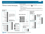
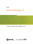
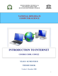
Mitel NuPoint Messenger Technical Documentation - Release 7.0
Unified TCP/IP Manual
Optional Feature
2700-1289-B1
Contents ©Copyright 2002, Mitel Networks Corporation
Distributed Courtesy of
http://www.promemoinc.com
P.O. Box 1899
Brentwood, CA 94513
Main: (925) 513-7510
Fax: (925) 775-7039
Support: [email protected]
Sales: [email protected]
General: [email protected]
©Copyright 2002, Mitel Networks Corporation
1
Mitel NuPoint Messenger Technical Documentation - Release 7.0
About This Manual
This manual describes how to install and configure the Unified TCP/IP harrdware and software in
any of the NuPoint Messenger Communications Servers:
•
Model 640
•
Model 120
•
Model 70
Who Should Read This Manual
This manual is intended for technicians and administrators who are responsible for installing and
configuring Unified TCP/IP on the NuPoint Messenger™ server.
How to Use This Manual
This manual contains detailed reference information, a list of tasks that you can perform, a
collection of procedures for performing the tasks, and reader aids such as menu maps.
Reference Chapters
Use the material in Chapters 1 through 4 for detailed inquiry into the installation and configuration
of Unified TCP/IP in a sMessenger server. These chapters discuss how components are related,
elaborates on concepts, give operational details, and contain all necessary tables and figures
about configuration. Use the Installation and Service Manual appropriate for your platform for an
actual server installation and the Reference and Configuration Manual for NuPoint Voice™
software configuration.
Task Lists
Task lists follow Reference chapters that include procedures. Use the task list, starting with a
principal task (shown in boldface), to install and configure Unified TCP/IP. Each task listed is
described in more detail in a procedure. The task list is alphabetized, which helps most readers
find the desired task (and procedure) quickly. No particular sequence of tasks is implied.
Procedures
Procedures follow the task list in the Reference chapter. Follow the steps in the procedures
(CPs) to accomplish the desired tasks. Readers familiar with a NuPoint Messenger server can
use the CPs as a checklist if desired, while readers new to a NuPoint Messenger server can use
CPs for step-by-step instructions.
A reference line in each CP contains pointers, when necessary, to supplemental information such
as another procedure, another manual, a technical reference, or a menu map.
Each CP is numbered for document identification and referencing; numbering does not indicate a
sequence of performance. A numerical list of all CPs in this manual is also provided. It gives
each CP’s title, Chapter number, and which other procedures either call it or are called by it.
©Copyright 2002, Mitel Networks Corporation
2
Mitel NuPoint Messenger Technical Documentation - Release 7.0
Menu Maps and Other Navigation Aids
Most of the documents in the NuPoint Messenger document library have menu maps. You can
refer to these document navigation aids at any point to help you reach a menu. In this manual,
you will also find a glossary of telecommunications, and telephony terms that pertain to TCP/IP.
Worksheets
You will find blank worksheets in the end of this manual. Instructions for completing the
worksheets are in the Reference chapters. Many of the CPs assume you have completed the
appropriate worksheet.
Conventions Used in This Manual
The procedures in this manual use the following conventions to describe how you enter Unified
TCP/IP configuration information and how information is displayed on the NuPoint Messenger
server console:
Press Enter
Press the Enter key. For example, "Press Enter if the current number is correct."
On some keyboards, this key is labeled "Return" or has a return arrow (↵) on it.
Enter
Type the text shown, then press the Enter key. For example, "Enter the line
number (1-24)" means type a number from 1 through 24, and then press the Enter
key.
bold
Words or characters in bold type indicate either a value to be entered by you
exactly as shown or, when used to indicate a variable entry, describe the type of
value to be supplied by you. See example above.
What you select from
a displayed menu
A displayed prompt
for information
ion.
What you enter in
response to the prompt
Note: Unless otherwise stated, press Enter after each response you enter.
Reader Advisories
Reader advisories used in this manual are shown below.
Note: Information especially useful in relation to this procedure.
©Copyright 2002, Mitel Networks Corporation
3
Mitel NuPoint Messenger Technical Documentation - Release 7.0
CAUTION!
Information that helps you prevent equipment or software damage.
CAUTION!
Information that helps you avoid electrostatic discharge (ESD) damage
to the equipment.
WARNING!
Information that helps you prevent an interruption to telecommunications
traffic.
WARNING!
A hazard that can cause you personal injury.
DANGER!
Warns of a condition that could severely injure or kill you.
Before You Start
This manual assumes that you are familiar with using a console and keyboard. This section
describes how to use the NuPoint Messenger server effectively.
Console Tips and Techniques
The tips and techniques offered in the following paragraphs can make configuration entry
sessions at the NuPoint Messenger server console more productive.
Viewing Menus
•
When you finish entering a value for a parameter, the server displays an abbreviated form of
the current menu, called the "short menu." To view the complete current menu when a short
menu is displayed, just press Enter.
•
To return to the Main Menu from any NuPoint Voice configuration menu, press X (Exit), until
the Main Menu appears.
Accepting Defaults
•
To accept a default displayed in a prompt, just press Enter.
•
To accept a default displayed in a menu, no action is necessary.
Avoiding Automatic Exit
CAUTION!
The NuPoint Messenger server "times out" after 15 minutes. This means
that if you do not enter anything at the console for 15 minutes, the server
automatically exits from the current program. When this happens, all
work that has not been saved on the disk is lost.
©Copyright 2002, Mitel Networks Corporation
4
Mitel NuPoint Messenger Technical Documentation - Release 7.0
To avoid being timed out and losing your work, follow these steps:
1. When you need time to think, write down the name of the current menu.
2. Exit to the (server) Main Menu.
3. When you want to continue your work, enter the appropriate menu options to regain your
place.
If you find that theserver has timed out, follow the steps below. If your screen is blank, press any
key to reactivate the screen and then continue with these steps.
1. Press any key to start the login sequence.
2. Enter your user ID and password (if requested).
3. Starting from the Main Menu, enter menu options to proceed to the menu from which the
server timed out.
4. Reenter data as needed to regain lost work.
Quitting an Entry Session
At any point during entry of offline or online parameters, you can quit. Quitting discards all
pentries you have made and leaves the NuPoint Voice configuration the way it was before you
started entering parameters.
To quit from the NuPoint Voice Configuration Offline or Online Menu:
Select:
Prompt:
Response:
(Q) Quit -- Forget Changes
Quit and forget changes? (y/n) =
Y to return to the NuPoint Voice Configuration Main Menu.
Shortcut Commands
You can use the Ctrl (Control) key or the / (slash) key while simultaneously pressing another key
to execute shortcut commands at a NuPoint Messenger server console.
To do this...
Activate a timed-out console.
From the offline or online menus, or FCOS, LCOS, GCOS
menus, return to the NuPoint Voice Configuration Menu and
save any entries.
From the offline or online menus, or FCOS, LCOS, GCOS
menus, return to the NuPoint Voice Configuration Menu without
saving any entries.
Stop scrolling a displayed report.
Resume scrolling a displayed report.
Return to the NuPoint Voice application when a # or $ prompt is
displayed.
Type...
any key
/X
/Q Y
Ctrl-S
Ctrl-Q
Ctrl-D or type exit
1 Introduction to Unified TCP/IP
This manual describes the Unified TCP/IP optional feature for the NuPoint Messenger server.
The Unified TCP/IP option allows you to connect the server to an Ethernet TCP/IP network using
an Ethernet card and TCP/IP software. Each server module can support two Ethernet cards.
©Copyright 2002, Mitel Networks Corporation
5
Mitel NuPoint Messenger Technical Documentation - Release 7.0
Product Dependencies
Unified TCP/IP requires software release 6.0A or later.
Two other products are dependent on the Unified TCP/IP application in order to function. Unified
TCP/IP is required to implement both the NP View optional feature and the NP Net TCP/IP
optional feature. Use this manual for Unified TCP/IP hardware and software installation and
configuration. Refer to the respective manuals for these products once you have the Unified
TCP/IP application working.
Existing Networks
One use of Unified TCP/IP is to connect your server onto an existing corporate network. Figure
1-1 shows how the NuPoint Messenger server is incorporated into an existing Ethernet network.
Figure 1-1 The NuPoint Messenger Server on an Ethernet Network
TCP/IP Protocol
TCP/IP stands for Transmission Control Protocol/Internet Protocol. It is a suite of
communications protocols used to link computers over many types of networks, including
Ethernet networks. Its features include:
•
Open standards, independent of vendor, hardware, and operating systems
•
Wide support and usage
•
Integration in many different network types
•
Common addressing method so a device can be recognized by any other device
•
Standardized application protocols for user services
The protocol stack has four layers: Network Interface (physical network access), Internet (routing
across internetworks), Transport (connectivity between data source and destination), and
Application (user programs and utilities).
For more information on TCP/IP, refer to Chapter 2. Refer to Chapter 4 for information specific to
the QNX 4.2 TCP/IP implementation and the NuPoint Messenger server.
Ethernet Networks
Ethernet is a type of Local Area Network (LAN) with various data transmission speeds including
ten megabits per second. Devices on the network communicate using thick coaxial, thin coaxial,
or twisted pair cable or wire. Communications at ten megabits per second are covered by the
10Base5, 10Base2 and 10Base-T standards respectively. If a data packet is sent by one device
and it collides with another message, the Ethernet protocol dictates that each message is
discarded, and then both are sent again after a random delay.
Hardware
The Ethernet card used in the Unified TCP/IP option is made by Alta. Refer to Chapter 3 for
©Copyright 2002, Mitel Networks Corporation
6
Mitel NuPoint Messenger Technical Documentation - Release 7.0
information about the hardware options and how to install the Unified TCP/IP hardware.
Software
You configure the Unified TCP/IP option by installing the software and following the instructions in
the procedures. Refer to Chapter 4 for information about Unified TCP/IP installation and
configuration.
2 Overview of TCP/IP
This chapter describes the TCP/IP protocol suite and explains a number of specific concepts. If
you are very comfortable working with TCP/IP, you can probably skip this chapter.
TCP/IP protocols were developed for the ARPANET network of computers, administered by the
Defense Communications Agency. This network began as an experimental packet switching
network and the organizations involved with the project found it useful for their data
communications. The TCP/IP protocol suite was adopted as a standard for ARPANET in 1983
and implemented in BSD UNIX, which led to its association with UNIX systems. TCP/IP is now
used by most UNIX systems, and many other host computers and peripheral devices can be
included in a TCP/IP network.
This chapter is not meant to provide complete coverage of TCP/IP. There are many good books
you can refer to for detailed information. One is TCP/IP Network Administration by Craig Hunt,
published by O’Reilly & Associates.
TCP/IP Protocol Layers
There are four layers in the TCP/IP protocol architecture. Here is a brief explanation of each
layer. Figure 2-1 shows the relationship between TCP/IP and the OSI model. This relationship is
not a perfect fit, but is helpful if you are already familiar with the OSI model.
Network Access Layer
This is the lowest layer of the architecture, and corresponds to the lowest two layers of the OSI
model (Data Link and Physical). The Network Access Layer protocols allow the system to deliver
data to other devices in a directly attached network. Functions performed include encapsulation
of IP datagrams into transmitted frames, and mapping of IP addresses to physical addresses
used by the network. Protocols implemented in this layer include device drivers.
Internet Protocol Layer
The most important protocol in this layer is the Internet Protocol, the IP in TCP/IP. The IP is used
to deliver data, as this layer provides routing functions (transferring information from one device
to another). IP defines the datagram, the basic unit of transmission. It also defines the Internet
addressing scheme. IP is connectionless, which means it does not verify that the receiving
system is ready to receive data. This layer corresponds to the Network Layer in the OSI model.
Figure 2-1 TCP/IP and the OSI Model
©Copyright 2002, Mitel Networks Corporation
7
Mitel NuPoint Messenger Technical Documentation - Release 7.0
Transport Layer
The full name for this layer is the Host-to-Host Transport Layer. It uses two protocols:
Transmission Control Protocol (TCP) and User Datagram Protocol (UDP). TCP provides reliable
(connection is made) data delivery service with error detection. UDP provides connectionless
datagram delivery service. Applications can use either protocol.
Both protocols deliver data between the Application Layer (see below) and the Internet Layer
(see above). TCP corresponds with the Transport Layer in the OSI model.
Application Layer
This layer includes any process using the Transport Layer (see above) protocols for data delivery.
There are many application protocols, most of which provide user services. The most widely
known are:
•
telnet, the Network Terminal Protocol, which provides remote login over the network
•
ftp, the File Transfer Protocol, which provides interactive file transfer
•
SMTP, the Simple Mail Transfer Protocol, which provides electronic mail
•
DNS, the Domain Name Service, which maps IP addresses to names assigned to network
devices
•
rip, the Routing Information Protocol, which is used by network devices to exchange routing
information
•
NFS, the Network File System, which allows files to be shared by different hosts on the
network. This protocol is not supported by the QNX 2 version of TCP/IP.
The Application Layer corresponds to the top three layers in the OSI model (Application,
Presentation, and Session).
IP Addresses
You should be familiar with IP addresses, because they are used by the Internet Protocol to send
datagrams from one node to another. A datagram includes a destination address, which is a 32bit IP address.
Address Classes
TCP/IP has 5 address classes – A, B, C, D, and E. Classes A, B, and C are available for
government and organizational use. Classes D and E are reserved for special use. This section
discusses classes A, B, and C.
Network and Host Numbers
Each address class uses one part of the 32-bit address to identify the network number and
another part to identify the host number. The demarcation for host and network numbers for
classes A, B, and C is one octet. An octet is eight bits and is usually represented as a decimal
number between 0 and 255. A group of four octets comprises an IP address. An example of an
IP address is 129.52.111.60. 129, 52, 111, and 60 are the four octets, each one representing a
series of eight bits.
Class A addresses use the first octet for network numbers and the next three for host numbers.
©Copyright 2002, Mitel Networks Corporation
8
Mitel NuPoint Messenger Technical Documentation - Release 7.0
Class B addresses use the first two octets for network numbers and the next two for host
numbers. Class C addresses use the first three octets for network numbers and the last octet for
host numbers. Table 2-1 summarizes this relationship.
Table 2-1 Network and Host Numbers
Class
Network Numbers
A
First octet
B
First and second octets
C
First, second, and third octets
Host Numbers
Last three octets
Last two octets
Last octet
Class Bits
Bits in the first octet identify address classes – the first bit identifies Class A, the first two bits
identify Class B, and the first three bits identify Class C. Table 2-2 shows the class bits for
address classes A, B, and C. Examine the figures in the table to see how the use of class bits
affects the number of usable network numbers.
Table 2-2 Class Bits and Network Numbers
Class
A
B
C
Class Bit
0
10
110
Network Bits
Class A uses the first octet for network numbers. Numbers 1 to 126 are the usable network
numbers. All addresses from 127.0.0.0 through 127.255.255.255 are reserved for local software
loopback tests. Class B uses octets one and two for network numbers. Usable network numbers
are 128.1 through 191.254. The number 255 is reserved for broadcasts. Class C uses octets
one, two, and three for network numbers. Usable network numbers are 192.0.1 through
223.255.254. Table 2-3 shows the relationship between classes and the network bits.
Table 2-3 Network Bits
Network. Bits
Class
A
7
B
14
C
21
First Usable
Network #
1
128.1
192.0.1
Last Usable
Network #
126
191.254
223.255.254
Host Bits
The rest of the IP address identifies the host. Table 2-4 shows the classes of IP format
addresses, expressed in bits. The illustration column shows the IP address format, in bits, where
n is the network portion of the address and h (italicized) is the host portion.
Table 2-4 IP Address Format (Bits)
Network
Host
First Bits Address Address
Length
Length
Class
A
B
C
0
10
110
7
14
21
24
16
8
Illustration
0nnnnnnnhhhhhhhhhhhhhhhhhhhhhhhh
10nnnnnnnnnnnnnnhhhhhhhhhhhhhhhh
110nnnnnnnnnnnnnnnnnnnnnhhhhhhhh
Table 2-5 shows the same information as the above table, presented in octet format. As in the
©Copyright 2002, Mitel Networks Corporation
9
Mitel NuPoint Messenger Technical Documentation - Release 7.0
previous table, the host portion of the address is in italics.
Table 2-5 IP Address Format (Octets)
First Octet
Network
Host Octets
(decimal)
Octets
Class
A
< 128
1
3
B
128 - 191
2
2
C
192 - 223
3
1
Example (decimal)
26.104.0.19
128.66.12.1
192.178.16.1
Reserved Addresses
Certain addresses are reserved, which means they are not available as host address IDs. An
example is addresses with a first octet above 223. Another is the Class A addresses 0 and 127;
0 is the default route, which is used to simplify routing information. 127 is the loopback address,
which allows the local host to be addressed as if it were a remote host. You use these addresses
when configuring any host.
In all address classes, host numbers 0 and 255 are reserved. When all host bits are 0, the
address identifies the network. These addresses, such as 128.66.0.0, are used in routing table
listings. If all host bits are 1, the address is a broadcast address and sends datagrams to all
hosts on one network (for example, 128.66.255.255).
Note: IP addresses are assigned to a network interface, not a computer system. Some devices have more
than one IP address because they are connected to more than one network.
Subnet Addressing
Organizations are often assigned one Class B network number by the Internet Advisory Board. If
the organization needs multiple network numbers to distinguish among its servers, the network
administrator uses subnet addresses to refer to the multiple networks. Subnet addressing is a
mechanism whereby address bits that would otherwise be part of the host number are designated
as part of the network number.
In a class B address, its format is nnnnnnnn.nnnnnnnn.hhhhhhhh.hhhhhhhh, where n stands for a bit
in the network number and h stands for a bit in the host number. To increase the amount of
available network numbers, host bits from the third octet are used as network bits, which, for each
bit borrowed, doubles the number of usable network numbers and halves the number of host
numbers. The format becomes, for example, nnnnnnnn.nnnnnnnn.nnhhhhhh.hhhhhhhh. Borrowing
bits from the host portion is accomplished using a subnet mask.
Subnet Mask
To create a subnet, you apply a bit mask, known as the subnet mask, to the IP address. If a bit is
on (1) in the mask, the equivalent bit in the address is treated as a network address bit, whether
or not it was a network bit originally. If the bit is off (0), then the equivalent address bit belongs to
the host address.
The subnet mask is a 32-bit number with a similar format as the IP address. Default subnet
masks are 255.0.0.0 for class A, 255.255.0.0 for class B, and 255.255.255.0 for class C.
Expressed in binary form, the network mask for class B is
11111111.11111111.00000000.00000000. Theoretically, in order to provide for two subnetworks
with 32,768 hosts per subnetwork, you could use the network mask 255.255.128.0. However,
because of restrictions on the use of some subnet values, you need to use the subnet mask
255.255.192.0 (the third octet is 11000000) to obtain two subnetworks, 01 and 10. The remaining
©Copyright 2002, Mitel Networks Corporation
10
Mitel NuPoint Messenger Technical Documentation - Release 7.0
six bits from the third octet, plus the entire fourth octet, are used for up to 16,384 host addresses.
(Network 00 identifies the network and 11 is for broadcast.)
Subnet masks can be expressed in bit or decimal format. While decimal format is easier to read,
remember that network address portions can cross the octet boundaries, and using the decimal
masks might be confusing in such cases.
Ask your network administrator if any subnet masks are used on your network.
Routing
Routing is the process of sending a message to either a destination host (if it is on the same
network) or a router or a gateway (if the host is on another network). Routing is based on the
network portion of the IP address. If the destination network is on the local network, the subnet
mask is applied.
Address Resolution
ARP, Address Resolution Protocol, translates IP addresses to Ethernet addresses. It maintains a
table of both sets of addresses, which is built dynamically.
Data Delivery
As data moves up and down the TCP/IP layers, each layer must be able to handle it. Data is
combined as it moves from applications to transport protocols, and then to the Internet Protocol.
Many sources of data are combined, and then must be separated when they arrive at the
destination network or host. IP uses protocol numbers to identify transport protocols, and the
transport protocols in turn use port numbers to identify applications.
Protocols
Some protocols are reserved for specific services, such as standard network protocols (for
example, ftp and telnet). They are defined in the file /etc/protocols. Figure 2-2 shows a sample
protocols file.
Note: This chapter has several examples of files used with TCP/IP, which are provided for your
understanding. You cannot access these files on the NuPoint Messenger server. Contact your
distributor should you need to change any TCP/IP files on the server.
# /etc/protocols
#
# format is:
#
# protocol
number
#
ip
0
icmp
4
tcp
6
udp
16
aliases
IP
ICMP
TCP
UDP
#
#
#
#
internet protocol, pseudo protocol
internet control message protocol
transmission control protocol
user datagram protocol
Figure 2-2 Sample /etc/protocols File
©Copyright 2002, Mitel Networks Corporation
11
Mitel NuPoint Messenger Technical Documentation - Release 7.0
Port Numbers
Port numbers below 256 are reserved for specific services (for example, ftp and telnet). Port
numbers from 256 to 1024 are reserved for UNIX-specific services, (for example, rlogin). These
numbers must be unique within a specific transport protocol. The combination of protocol and
port number identifies a process to send the data to. Port numbers are defined in the file
/etc/services. Figure 2-3 shows a sample services file.
# /etc/services
# format is:
# service
port/protocol aliases
#
# Network services
#
ftpdata
20/tcp
ftpd
ftp
21/tcp
telnet
23/tcp
telnetd -d
smtp
25/tcp
bootps
67/udp
bootpd
bootpc
68/udp
bootp
tftp
69/udp
tftpd
snmp
161/udp
snmpd
echo
7/tcp
echo
7/udp
discard
9/tcp
sink null
discard
9/udp
sink null
daytime
13/tcp
daytime
13/udp
chargen
19/tcp
ttytstsource
chargen
19/udp
ttytstsource
time
37/tcp
timserver
time
37/udp
timserver
finger 79/tcp
domain
53/tcp
nameserver
#name-domain server
domain
53/udp
nameserver
nb_nmsrv
137/udp
netbios nameserver
nb_sssrv
139/tcp
netbios session server
nb_dgsrv
138/udp
netbios datagram server
#
# UNIX specific services
#
exec
512/tcp
login
513/tcp
rlogin rlogind
shell
514/tcp
rsh rshd cmd
who
513/udp
rwho rwhod who
ntalk
518/udp
route
520/udp
router routed
1000/tcp
qnxserver
Figure 2-3 Sample /etc/services File
Sockets
As mentioned above, certain port numbers are standardized for specific services. Other port
numbers can be dynamically allocated, and are assigned to processes as needed. The system
keeps track of these port numbers and ensures that one number is not assigned to two
processes. These dynamically assigned ports allow services to support multiple users.
If two users are accessing the TELNET service, for example, the system would give each of them
a different dynamically assigned port number for the source port, and the default port of 23 for the
©Copyright 2002, Mitel Networks Corporation
12
Mitel NuPoint Messenger Technical Documentation - Release 7.0
destination. The pair of port numbers, both source and destination, identifies a network
connection. The combination of an IP address and a port number is called a socket. A socket
identifies a single network process within the Internet. A pair of sockets uniquely identifies a
network connection between a receiving and a sending host.
For example, if host 128.66.12.2 connects to host 192.178.16.2 using TELNET, and is assigned
port 3382, the socket for the source side of the connection is 128.66.12.2.3382. The destination
side socket is 192.178.16.2.23 (defaulting to the TELNET port number). These two sockets are a
socket pair, and this identifies the connection. If another user from the same host connects to the
same destination with TELNET, the second user would get a different source port number, for
example 3610. The socket pair for this user would be 128.66.12.2.3610 and 192.178.16.2.23.
Name Services
It is easier to use names for hosts than IP addresses. Names are easier to remember, and it is
easier to notice a mistake in a name. Here are two services that allow you to use alphabetic
names instead of numerical IP addresses..
Host Table
The host table associates the addresses and names. You can also designate aliases for hosts in
this table. The table is in the file /etc/hosts. There is also a file called /etc/networks, which can
translate between network names and network IP addresses. Figure 2-4 shows a sample
/etc/hosts file.
#
# Table of IP addresses and host names
#
128.66.12.2
mast.sail.com yacht
127.0.0.1
localhost
128.66.12.1
main.sail.com loghost
128.66.12.3
jib.sail.com jib
128.66.12.4
spinnaker.sail.com spinnaker
128.66.5.2
genoa.sail.com genoa
128.66.7.3
boom.sail.com boom
128.66.7.2
halyard.sail.com halyard
Figure 2-4 Sample /etc/hosts File
Most large networks use DNS instead of the host table, but it is used for small networks or for all
hosts on the local network, in case DNS is not running.
DNS
The Domain Name Service is used in large interconnected networks because it avoids the
problems of a large host table. It also eliminates the need to keep updating your table as new
hosts are added or changed. DNS is assigned port number 53, and its service is called domain.
Do not confuse it with name service, port 42 (this is an older name service).
DNS is a set of distributed name servers which pass information to each other as needed. The
naming conventions are hierarchical. At the top level is the root domain, served by a group of
name servers called root servers.
There are two top-level domains, geographic and organizational. Geographic domains are
©Copyright 2002, Mitel Networks Corporation
13
Mitel NuPoint Messenger Technical Documentation - Release 7.0
assigned by country; each country has a two letter code. Other assignments are made
underneath the country code. In the United states, the next level is the two-letter state code.
Thus, a valid domain name could be myhost.sanjose.ca.us. The highest level of the domain is the
last part of the name.
The second type of top-level domain is organizational; assignment is made based on what kind of
group is using the host. The top-level domains are listed in Table 2-6.
Table 2-6 Top Level Domains
Domain
Name
Used By
COM
Commercial organizations (businesses)
EDU
Educational sites (schools, colleges, universities)
GOV
Government agencies and groups, not including military
MIL
Military organizations
NET
Network support organizations, such as sites that run root servers
ORG
Any organization that is not one of the above (for example, non-profit groups)
Again, the highest level of the domain is the last part of the name. A valid domain name is
whitehouse.gov; whitehouse is a site on the government domain. In both cases, domain names
are written from most specific (for example, host name) to least specific (top-level domain).
3 Hardware Installation and Configuration
WARNING!
To install, configure and use the Unified TCP/IP option, you must have
software release 6.0A or later installed on your server. You also must
have the 6.0A hardware, including the 6.0A Ethernet card. Ethernet
cards used in 5.x servers are not usable.
This chapter contains reference and background material for the hardware installation and
configuration. Refer to the Task List for step-by-step instructions on Unified TCP/IP installation
and configuration.
Ethernet Hardware
In order to connect your NuPoint Messenger server to an Ethernet network, you need an Ethernet
card. The Unified TCP/IP option includes an Ethernet card that you install in a server module.
You need at least one Ethernet card per server, and you can install up to two cards per module.
There are three kinds of cabling that can be used in Ethernet networks: thick, thin, and twisted
pair. Thick Ethernet uses 0.4 inch diameter, 50-Ohm, double shielded coaxial cable, based on
IEEE standard 802.3 10Base 5. Thin Ethernet uses 0.2 inch diameter, 93-Ohm coaxial cable,
based on IEEE standard 802.3 10Base 2. Twisted pair Ethernet uses unshielded twisted pair
cable (AT&T D-inside wire or IBM Type 3), based on IEEE standard 802.3 10Base-T. The cable
is two sets of twisted wire pairs, with a gauge of 22, 24, or 26. All three standards can handle a
data rate of at least 10 megabits per second.
The Ethernet card provided with the Unified TCP/IP option has a twisted-pair connector (an RJ-45
connector) for 10Base-T wiring. If you have thin or thick Ethernet cabling, you must purchase a
transceiver to interface between your cabling and the Ethernet card’s RJ-45 connector. These
©Copyright 2002, Mitel Networks Corporation
14
Mitel NuPoint Messenger Technical Documentation - Release 7.0
transceivers are available through many vendors, such as MiLAN and Cabletron.
For complete information on the Ethernet card, refer to the Technical Reference in the Technical
Reference Manual.
Hardware Limitations
The Ethernet card cannot coexist in the same module with the following cards because of
interrupt conflicts:
•
Smartcard (2, 4, or 8 port serial card)
•
PROSE™ TTS card
Do not include an Ethernet card in the same module as any of the above cards.
Configuring the Hardware
This section shows how you must configure the Ethernet to use the Unified TCP/IP optional
feature successfully.
Configuring the Ethernet Card
There are two different ways to configure an Ethernet card with the Unified TCP/IP optional
feature. These configurations are designated as either "Ethernet 1" or "Ethernet 3." The
Ethernet cards are configured by your distributor and you should check with your sales
representative to ensure you have the correct card for your server configuration. Refer to the
Technical Reference Manual for more information on Ethernet card configuration, how they differ,
and which to use in your server.
Fault Tolerance
Fault tolerance is configured by installing the Unified TCP/IP option in at least two modules. If
one module fails, another module could take over, and all TCP/IP commands server-wide would
be directed to the other module. You can also install two Ethernet cards in the same module,
provided you configure the cards correctly. Refer to Chapter 4 for more information.
At this time there is no CSO (Continuous System Operation) transfer between Ethernet cards.
This capability will be supported in future releases. In addition, neither NP View 1.1 nor NP Net
TCP/IP are capable of handling the live transfer from one Ethernet card to another.
One Ethernet card can handle all TCP/IP network traffic for a server, including both the NP View
and NP Net applications. You might need more cards if your server handles a large number of
messages.
Hardware Task List
Unified TCP/IP Hardware Procedures
Install Ethernet Card---------------------------------------------------------------------CP 2149
Connect the Server to the Network --------------------------------------------------CP 2150
©Copyright 2002, Mitel Networks Corporation
15
Mitel NuPoint Messenger Technical Documentation - Release 7.0
Shut Down a Server ---------------------------------------------------------------------CP 5700
CP 2149 Install the EtherTPI-16+T Ethernet
This procedure describes how to install the Alta EtherTPI-16+T Ethernet card in a NuPoint
Messenger server for use with the Unified TCP/IP optional feature.Note: You perform diagnostic
and troubleshooting tasks after you install and configure Unified TCP/IP on the server. See CP
6472, "Test Unified TCP/IP Configuration," in Chpater 4, for instructions.
Procedure Steps
1. Make sure that you are wearing an electrostatic discharge (ESD) strap.
2. Do an orderly shutdown of the server (or module in a multi-module system), making
certain to turn off the power to the module in which you want to install the Ethernet
card.
Reference: CP 5700
CAUTION!
Do an orderly shutdown of the server and turn off the server module
before doing the next steps.
3. Remove the front cover of the CPU assembly.
4. Carefully remove the Ethernet card from its ESD envelope and place the card on an
anti-static surface.
5. Ensure that you have the correct card for your system’s configuration (Ethernet 1 or
Ethernet 3). Refer to the Technical Reference Manual for further information on card
configuration.
6. Insert the card into the appropriate backplane slot and make sure that the card is
firmly seated on the backplane connector. Tighten the card’s retaining screw.
7. Replace the front cover of the CPU assembly.
8. Restore power to your server (or module in a multi-module system) and allow the
system software to start up.
Figure 1 Alta EtherTPI-16+T Ethernet Card
CP 2150 Connect the Server to the Network
This procedure tells you how to connect the Ethernet card in the NuPoint Messenger server to the
Ethernet network, using twisted-pair cable.Note: The network administrator must pull cable to the
server and provide you with a network connection before you perform this procedure.
Procedure Steps
Connect Ethernet Card to Twisted-Pair Cable
1. Insert the modular plug shown in Figure 1 into the RJ-45 port on the Ethernet card.
©Copyright 2002, Mitel Networks Corporation
16
Mitel NuPoint Messenger Technical Documentation - Release 7.0
Figure 1 Connecting Ethernet Card to Twisted-Pair Cable
2. Verify the connection by observing the green link integrity LED on the Ethernet card
(see Figure 2). When a valid connection exists, the LED on the card and the
corresponding LED on the network concentrator are lit. (The network administrator
verifies the network connection.)
Figure 2 LEDs on Ethernet Card
CP 5700 Shut Down a Server
This procedure describes how to shut down a module or an entire NuPoint Messenger server.
You should use this procedure before turning off the power to a module, as the shutdown
command halts call processing in a clean and orderly fashion.
WARNING!
You should follow the policies of the site to warn users prior to the server
shutdown. This process removes the server from call processing. It is
recommended that you perform this procedure only during periods of low call
traffic.
Procedure Steps
1. Reach the System Maintenance Menu.
Reference: Menu Map 1
2. Execute a shutdown command.
(S) System Shutdown
Select:
• The server displays the status of each line and the lengths of the message
indicator request queues.
WARNING!! This will terminate call processing.
Prompt:
Type "shutdown" if you really want to do this.
Response: shutdown
3. If you have a multi-module system, specify which modules to shut down.
modules to shutdown:
Prompt:
Response: a for all modules, or the number of a specific module (1, 2, 3, or 4).
You can select multiple modules by entering the IDs separated by
commas (3,4), or a range by using a hyphen (2-4).
• The server displays the status of each line of the specified modules as "idle,"
"active," or "stopped," and updates the status every minute until all lines are
stopped. The server stops any calls still in progress after five minutes.
4. If you are executing a server shutdown, wait for the message waiting queue to
clear. If you are executing a module shutdown on a multi-module server, do not
wait for the message waiting queue to clear.
Wait for message waiting queues to be empty?
Prompt:
Response: Y to wait for the queue to clear, or
N to continue immediately with the shutdown.
5. When the server has taken all lines of the specified modules off-hook, it continues
by asking if a verify is to be executed.
Perform Offline System Verification? (Y/N):
Prompt:
©Copyright 2002, Mitel Networks Corporation
17
Mitel NuPoint Messenger Technical Documentation - Release 7.0
Y to execute the verify, or
N to skip verify and continue with the shutdown.
6. Specify if changes to the status of each module are to be made.
Enable or Disable Modules?
Prompt:
Response: Y to change the status of modules, or
N to keep the module status the same and continue at step 11
7. If you answered yes in step 6, a chart with the status of each module is displayed
and then the Module Maintenance Menu is displayed.
Response:
8. Enable a module, if necessary:
(E) ENABLE a module
Select:
Which Module?
Prompt:
Response: The number of the module.
9. Disable a module, if necessary:
(D) DISABLE a module
Select:
Which Module?
Prompt:
Response: The number of the module. If you are disabling multiple modules,
disable the module attached to the console last.
type "disable" to confirm your request:
Prompt:
Response: disable
If you are disabling multiple modules, repeat this step.
If the status of the module attached to the console was changed to disabled, the
balance of this procedure is not seen, due to the module resetting. The console
then resets to the Maintenance From Hard Disk Menu.
10. When you are done configuring the modules, exit the menu.
11. The server completes the shutdown.
****SHUTDOWN COMPLETE****
Prompt:
The System Maintenance Menu is displayed. You can now either reboot the
module(s) or remove power to the module(s).
4 Software Installation and Configuration
This chapter covers reference information relating to the Unified TCP/IP software, including
installation and configuration. Refer to the Task List for step-by-step instructions on software
installation and configuration.
Installing the Unified TCP/IP Software
This section provides an overview on installing the Unified TCP/IP software on your NuPoint
Messenger server.
Note: For complete step-by-step directions, refer to the procedures at the end of this chapter.
Installing the Unified TCP/IP Optional Feature
You install the Unified TCP/IP software as an optional feature, using the service procedure. You
are prompted to insert the Unified TCP/IP optional feature diskettes. After you install the
©Copyright 2002, Mitel Networks Corporation
18
Mitel NuPoint Messenger Technical Documentation - Release 7.0
software, you can configure Unified TCP/IP at any point.
Configuring the Unified TCP/IP Application
Note: For complete step-by-step directions, refer to the procedures at the end of this chapter.
To configure the Unified TCP/IP software, you need a list of IP addresses and host names. You
also must have already installed the software as described in the above section.
Complete one worksheet per Ethernet card before configuring the application. Refer to Table 4-1
for help with the parameters. You should consult with your network administrator to obtain
appropriate IP addresses. Once you have completed your worksheet(s), you can configure the
application. Configuration takes place in the Offline Configuration Menu. If you are installing
more than one Ethernet card on your server, you must perform the software configuration for
each card.
A sample worksheet is shown in Figure 4-1. A blank worksheet, which you can use to make
copies, is in the next section after this chapter.
Table 4-1 Configuration Parameters for Unified TCP/IP
Parameter
Description
Domain Name
A name for a series of nodes, attached to the node name to form a
complete internet site name. For examples, if the domain name is
centigram.com, prepending the node name vm600 creates an
internet site name of vm600.centigram.com.
Current Module
The module number where the Ethernet card is installed, from 1 to 4.
Number
The default is 1.
Enable/Disable
Specify whether the card you are configuring should be Enabled
Current Card
(allowed to operate) or Disabled (not used). If the card is disabled,
NP Net TCP/IP and NP View 1.1 cannot operate either.
Ethernet Card
The type of configuration for the Ethernet card, either 1 or 3. This is
Configuration
fully explained in Chapter 3.
Node Name
The unique node name in the domain specified (see Domain Name,
above). Valid characters are alphanumeric and the underscore (_)
character.
Node IP Address The IP address of the Ethernet card being configured. It must be a
unique ID on the network. IP addresses are in the form x.y.z.w,
where each letter represents a number between 0 and 255.
Subnet Mask
This subdivides networks into sub-networks, for example,
255.255.255.0 is the default subnet mask for Class B networks. See
Chapter 2 for more information.
Network Number The physical network number. Network numbers 1 and 2 are
reserved for Q-Net and Redundant Q-Net. Therefore, all Ethernet
segments start with network 3, which is the default. The highest
allowable number is 9.
Broadcast Address Refers to all nodes on the TCP/IP network. A broadcast IP address
is a network ID with all 0 bits set to 1. For example, 129.32.255.255
is the broadcast address for network 129.32.0.0.
Operation Mode
Sets the IP address to be the primary (P) or the secondary (S). The
primary IP address is used to bind the TCP/IP stack on a module
and there can be only one primary IP address per module.
Current Card Slot The slot number where the Ethernet card is installed in the module
Number
specified.
Gateway IP
The IP address of the Internet gateway (the machine that
Address
communicates with the rest of the Internet).
©Copyright 2002, Mitel Networks Corporation
19
Mitel NuPoint Messenger Technical Documentation - Release 7.0
TELNET
configuration
Specify whether the card you are configuring should have telnet
services Enabled (allowed to operate) or Disabled (not used).
Figure 4-1 Sample Unified TCP/IP Application Worksheet
Two items are shown on the worksheet that are not covered in Unified TCP/IP configuration, and
those are the checkboxes for whether to install NP Net or NP View. These appear on the
worksheet to remind you that once you have installed and configured Unified TCP/IP, you should
install these options if you have them.
Connecting the Server to a Network
Note: For complete step-by-step directions, refer to the procedures at the end of this chapter.
The Ethernet card has an RJ-45 port which allows connection to unshielded twisted-pair
(10BaseT) Ethernet wiring. Insert the RJ-45 plug into the RJ-45 port on the Ethernet card. The
other end of the wire should be connected to a prewired wall jack or a concentrator or hub on
your network.
Verify the connection by powering on both the server and the concentrator or hub. Look for the
green Link Integrity LED on the Ethernet card; it should be lit if the connection is good. The
corresponding light on the concentrator should also be lit.
If the Polarity LED is lit, then the automatic polarity correction feature is working, and the signal
polarity is reversed. (This means the wiring had inverse polarity to begin with.)
The Transmit/Receive LED is lit when the card is transmitting or receiving data across the
network. The Collision Detection LED lights when collisions are detected on the network, which
is a normal condition.
Refer to Figure 4-2 for an illustration of the LEDs on the Ethernet card.
Figure 4-2 Ethernet Card LEDs
Testing the Installation and Configuration
If you cannot communicate over the network, you must check both the hardware and the software
for problems.
Testing the Hardware
Check the following for hardware problems:
•
Ensure the card is firmly seated in its slot and that it is receiving power.
•
Check the wiring connection to both the card and the wall jack or concentrator.
•
Check that your card is configured for an RJ-45 connector (jumpers 2 and 3). See Chapter 3
for information on card jumpering.
•
Ensure that the wiring is within the range allowed.
©Copyright 2002, Mitel Networks Corporation
20
Mitel NuPoint Messenger Technical Documentation - Release 7.0
•
Check that the green Link LED is lit. If it is not lit, check cabling of other computers
connected to the same concentrator. If none are lit, verify that the cables and hub are
operational.
•
Check the red Collision LED. If it is solid red or red most of the time, excessive collisions are
occurring on the network. Solid red can also indicate an incorrect cable type configuration;
check the jumper settings.
Refer to the Technical Reference Manual for more information on specifications, wiring, and
settings.
Testing the Connection With Ping
If the connection fails but the hardware appears functional, the board may not be configured
properly. Contact your customer support representative.
First, ping the server IP address from another node on your network. To do this, enter one of the
following addresses to ping:
•
Module’s host name
•
Module’s IP address
If this works (see Figure 4-3), the network is set up correctly. Ping each module in the system to
verify that all TCP/IP modules can communicate with each other.
Pinging host cgram: 188.15.7.20
ICMP Echo Reply: TTL 60
ICMP Echo Reply: TTL 60
ICMP Echo Reply: TTL 60
ICMP Echo Reply: TTL 60
Host cgram replied to all 4 of the 4 pings.
Figure 4-3 Successful Ping Results
If this succeeds, the software is probably set correctly.
Note: If pinging the module name does not work, ping the module IP address. If the IP address works,
there is a problem with name services on your network (/etc/hosts has the wrong values or DNS is
not working properly).
Worksheet
You can make copies of the blank worksheet. Use worksheets to configure your NuPoint
Messenger server for the Unified TCP/IP Application.
Unified TCP/IP Application Worksheet
Sotware Task List
Unified TCP/IP Software Procedures
Unified TCP/IP Optional Feature Installation ---------------------- CP 6470
Install and Configure Unified TCP/IP Software -----------------------------------CP 6471
Install an Optional Feature-------------------------------------------------------------CP 5402
©Copyright 2002, Mitel Networks Corporation
21
Mitel NuPoint Messenger Technical Documentation - Release 7.0
Test Unified TCP/IP Configuration ---------------------------------------------------CP 6472
CP 6470 Unified TCP / IP Optional Feature Installation
This procedure gives an overview of how to install, configure, and test both hardware and
software for the Unified TCP/IP Optional Feature. This feature allows you to put your NuPoint
Messenger server on an Ethernet network and communicate with other nodes attached to the
network. It also allows you to use Ethernet communications with the NP Net and NP View
optional features.
Procedure Steps
1. Ensure you have everything you need to install Unified TCP/IP. You should have at
least one Ethernet card, the Unified TCP/IP software, and the Unified TCP/IP
software manual. You will also need any other manuals referred to in this
procedure.
2. Make a copy of the Unified TCP/IP Application worksheet and fill out one copy per
Ethernet card. Consult with your network administrator for IP addresses, node
names, and other network issues.
3. Install the Ethernet card(s) into the server. If you are new to installing components
in your server, refer to the appropriate hardware manuals to familiarize yourself with
the server’s design (Installation and Service Manual).
Reference: CP 2149, Ch. 3
4. Install the Unified TCP/IP software on your server.
Reference: CP 5402
5. Configure the Unified TCP/IP software.
Reference: CP 6471
6. Connect the Ethernet card to the network.
Reference: CP 2150, Ch. 3
7. Test the hardware and software configuration. If the server responds correctly, you
can now communicate between the server and other nodes on the network. If you
wish to install the NP Net or NP View optional features to work with TCP/IP, install
and configure them now. Refer to the appropriate manuals to do so.
Reference: CP 6472
CP 6471 Configure Unified TCP IP Software
This procedure explains how to install the software for the Unified TCP/IP application, and how
to properly configure the software to use the application. It assumes that you have already
performed the following steps:
•
Installed one or more Ethernet cards correctly (CP 2149, Chapter 3)
•
Completed one worksheet per Ethernet card (CP 6470)
•
Installed the Unified TCP/IP software (CP 5402)
You must perform this procedure once per Ethernet card installed.
Procedure Steps
©Copyright 2002, Mitel Networks Corporation
22
Mitel NuPoint Messenger Technical Documentation - Release 7.0
1. Reach the Offline Configuration Menu, then go to the Unified TCP/IP Configuration
Menu.
Reference: Menu Map 13
2. Refer to your worksheet in specifying the parameters needed to use Unified
TCP/IP. First set the domain name for the Ethernet card.
(D) Domain Name
Select:
Enter the domain name
Prompt:
Response: The domain name from your worksheet Domain names are usually in
the form xxxxxxx.xxx, where the x’s represent alphanumeric
characters. Refer to Chapter 2 for more information on domain
names.
3. Set the module number that the Ethernet card was installed in.
(M) Configure a Module
Select:
TCP ETHERNET MENU:
Prompt:
(C) Current Module Number = [1]
Select:
Current Module Number = [1] ?
Prompt:
Response: The module number from your worksheet. Modules are numbered from
1 to 4. The Model 70 and Model 120 servers only have one module,
which is number 1.
4. Enable the Ethernet card. This allows the card to operate. If the card is disabled,
you cannot use Unified TCP/IP to communicate with other nodes, nor can you use
NP Net TCP/IP or NP View 1.1.
(D) Enable or Disable Current Card = [Disable]
Select:
Enter the status of current Ethernet card, (E)nable
Prompt:
or (D)isable = [Disable]
Response: E to enable the Ethernet card , or
D to disable the Ethernet card, so it cannot be used.
5. Specify the Ethernet card configuration type. For more information on card
configuration, refer to Chapter 3.
(E) Ethernet Card Configuration = [1]
Select:
Prompt:
Response:
Enter host Ethernet card configuration =
[1] ?
The configuration number for the Ethernet card. Valid values are 1 and
3.
6. Specify the node name for the Ethernet card.
(H) Node Name = []
Select:
Enter the node name of the card = [] ?
Prompt:
Response: The node name for the Ethernet card. A node name is prepended
before the domain name (see Step 2) to form an address. The node
name can contain alphanumeric characters and the underscore (_).
For more information on node addresses, refer to Chapter 2.
7. Specify the node IP address for the Ethernet card.
(I) Node IP Address = []
Select:
Enter the local IP address = [] ?
Prompt:
Response: The IP address for the Ethernet card. An IP address has the form
nnn.nnn.nnn.nnn, where each nnn refers to a number between 0 and
255, and the numbers are separated by periods. Refer to Chapter 2
for more information on IP addresses.
8. Specify the subnet mask for the Ethernet card.
(M) Subnet Mask = []
Select:
Enter the subnet mask = [] ?
Prompt:
©Copyright 2002, Mitel Networks Corporation
23
Mitel NuPoint Messenger Technical Documentation - Release 7.0
Response:
The subnet mask for the Ethernet card. A subnet mask is used to show
how a subset of the network uses IP addressing. The mask has the
form nnn.nnn.nnn.nnn, where each nnn refers to a number between 0
and 255, and the numbers are separated by periods. Refer to
Chapter 2 for more information on subnet masks.
9. Specify the network number for the Ethernet card.
(N) Network Number = []
Select:
Enter the network number of the card = [] ?
Prompt:
Response: The network number for the Ethernet card. Valid values are 3 through
9; 3 is the default. If you only have one network for your server, use
3.
10. Specify the broadcast address for the Ethernet card.
(O) Broadcast Address = []
Select:
Enter the broadcast address = [] ?
Prompt:
Response: The broadcast address for the Ethernet card. This is an IP address used
for all nodes on the Ethernet network. An IP address has the form
nnn.nnn.nnn.nnn, where each nnn refers to a number between 0 and
255, and the numbers are separated by periods. For more
information on broadcast addresses, see Chapter 2.
11. Specify the operation mode for the Ethernet card’s IP address (set in Step 7).
(P) Operation Mode (Primary/Secondary) = [Secondary]
Select:
Do you want to set this IP address as (P)rimary or
Prompt:
(S)econdary = [Secondary] ?
Response: P to set this address to primary operation mode, or
S to set this address to secondary mode.
The primary IP address is the address used by the TCP/IP utilities to
identify themselves on the network. There should be one and only
one primary IP address on a module. If you only have one Ethernet
card in a module, set it to operate as the primary.
12. Specify the slot number where you installed the Ethernet card.
(S) Current Card Slot Number = [0]
Select:
Enter the slot number of the card = [0] ?
Prompt:
Response: The slot number where the Ethernet card was installed. Refer to
Chapter 3 for more information on the valid slots to install Ethernet
cards.
13. Specify the gateway IP address for the Ethernet card.
(T) Gateway IP Address = []
Select:
Enter the Gateway IP address = [] ?
Prompt:
Response: The gateway IP address for the network. This is an IP address for a
node that communicates with other parts of the network. An IP
address has the form nnn.nnn.nnn.nnn, where each nnn refers to a
number between 0 and 255, and the numbers are separated by
periods. Refer to Chapter 2 for more information on gateway IP
addresses.
14. Enable the Ethernet card. This allows the telnet service to operate.
TELNET Configuration (Enable/Disable) = [Disabled]
Select:
Do you want TELNET service (E)nabled or (D)isabled
Prompt:
= [Disabled] ?
Response: E to enable the telnet service , or
D to disable the telnet service, so module cannot be accessed.
Note:
The default condition is to have telnet service disabled. You do not
need to enable telnet to use the Unified TCP/IP application with
either the NP Net TCP/IP or the NP View 1.1 optional features.
©Copyright 2002, Mitel Networks Corporation
24
Mitel NuPoint Messenger Technical Documentation - Release 7.0
15. Review the configuration settings.
(W) Show System Wide TCP/IP configuration
Select:
Response: Verify that the screen displays the Unified TCP/IP configuration
parameters you specified. Figure 1 shows a sample of the output.
Most items should be self-explanatory. The non-obvious items are:
Parameter
Explanation
Host
Module number
Card
Configuration type (1 or 3)
Mode
(P)rimary or (S)econdary
Slot Slot Number of module where card was installed
Net Server Network Number
Port
Starting memory address
IRQInterrupt Number
Vendor
Type of card
TCP/IP System Wide Host Configuration
------------------------------------Domain name: bayptin.com
H C M S
o a o l N
s r d o e
t d e t t
IP Address
Host Name
Port Irq Vendor
---------------------------------------------------------------------3 1 P 6 3
129.1.250.108
alpha199
0280 10 ALTA #1
Host Card
Gateway Address
Subnet Mask
Broadcast Address
---------------------------------------------------------------------3
1
129.2.7.2
255.255.0.0
129.1.255.255
Figure 1 Sample Output: Unified TCP/IP Configuration Display
16.
17.
18.
Exit the TCP Ethernet Menu.
Repeat step 2 through step 16 for any additional Ethernet cards installed in
your server.
Exit the TCP/IP Network Configuration Menu. Save your configuration settings
by exiting the Offline Configuration Menu.
CP 6472 Test Unified TCP / IP Configuration
This procedure explains how to test the hardware and software configuration for the Unified
TCP/IP application. It assumes that you have already performed the following steps:
•
Installed one or more Ethernet cards correctly (CP 2149, Chapter 3)
•
Completed one worksheet per Ethernet card (CP 6470)
•
Installed the Unified TCP/IP software (CP 5402)
©Copyright 2002, Mitel Networks Corporation
25
Mitel NuPoint Messenger Technical Documentation - Release 7.0
•
Configured the Unified TCP/IP software (CP 6471)
You must perform this procedure once per Ethernet card installed.
Procedure Steps
Test the Configuration
1. Watch the boot process to see if any errors appear indicating that the Ethernet card
is missing or is not seated properly. The messages appear after about one or two
minutes. Some of the errors might be:
CMN_ERR: 2 8003: LOCATE_8003(): AUTO-DETECT FAILED,
CAN’T DETERMINE CARD PARAMETERS
CMN_ERR: 2 8003: ED_INIT(): ETHERNET CARD NOT LOCATED
NETD: FAILED TO OPEN DRIVER "/DEV/ETH" ()[0])
CAUTION!
Do an orderly shutdown of the server and turn off the server module
before doing the next step.
2. If any of these errors appear, remove the front cover of the CPU assembly and
reseat the Ethernet card. If you continue to see these errors, replace the Ethernet
card with a new one.
3. Check the Error Log to see if the Ethernet card installation has introduced any
errors.
4. Test if the hardware and software were installed properly by using ping. Perform
this test from another node on the network and attempt to ping the server. You may
need help from your network administrator. Use the IP address of an Ethernet card
you configured for the server.
If the test is successful, you see a message similar to the following one.
Pinging host 129.1.11.25
ICMP Echo Reply: TTL 60
ICMP Echo Reply: TTL 60
ICMP Echo Reply: TTL 60
ICMP Echo Reply: TTL 60
Host 129.1.11.25 replied to all 4 of the 4 pings.
If the ping test is successful, you can assume that the network connection between
the server and the computer you are using is working properly. If the ping test is
unsuccessful, you will receive an error message (for example, the message might
say that the node is unreachable).
If the test is unsuccessful, check the physical connections between the server and
the network, including the Ethernet cards, the cable, and the connectors. If you
continue to have problems, consult with the network administrator at the customer
site. Refer to Troubleshooting, below.
5. Start a telnet session from another site to the server. Refer to Troubleshooting,
below, if telnet does not work properly. Contact your network administrator for
information on using telnet.
Troubleshooting Checklist
1. Ensure the Ethernet card is firmly seated in its slot and that it is receiving power.
2. Check the wiring connection to both the card and the wall jack or concentrator.
©Copyright 2002, Mitel Networks Corporation
26
Mitel NuPoint Messenger Technical Documentation - Release 7.0
3. Check that your card is configured for an RJ-45 connector. Refer to the Technical
Reference Manual for more information on card configuration.
4. Ensure that the wiring is within the range allowed. Refer to the Technical Reference
Manual for more information on wiring standards.
5. Check that the green Link LED is lit. If it is not lit, check cabling of other computers
connected to the same concentrator. If none are lit, verify that the cables and hub
are operational. See Figure 1.
Figure 1 LEDs on the Ethernet Card
6. Check the red Collision LED (Figure 1, above). If it is solid red or red most of the
time, excessive collisions are occurring on the network. Solid red can also indicate
an incorrect cable type configuration. Refer to the Technical Reference Manual for
more information on card configuration.
7. Reach the TCP/IP Network Configuration Menu.
Reference: Menu Map 13
8. Run a System-Wide Configuration Report. You will need this report to perform the
next few steps. Refer to any worksheets you completed to check for
misconfiguration.
9. Ensure that you installed the Ethernet card(s) in the correct slot for your system,
and that you used the correct card configuration(s). Verify all jumper settings.
Refer to the Technical Reference Manual for hardware configuration tables.
10. If you have more than one Ethernet card installed in your server, verify that each
has a unique IP address, and that you are using them consistently.
11. Ensure that one, and only one card per module is set as the primary address. (The
Mode heading shows if a card is set to Primary or secondary.)
12. Reach the Ethernet Card Menu.
Reference: Menu Map 13
13. If you cannot get any response from the server Ethernet card, ensure that the card
is enabled. (This is not indicated in the Configuration Report; you must perform this
operation in the Ethernet Card Menu to determine the card setting.)
(D) Enable or Disable Current Card = [Disable]
Select:
Enter the status of current Ethernet card, (E)nable
Prompt:
or (D)isable = [Disable]
Response: E to enable the Ethernet card , or
D to disable the Ethernet card, so it cannot be used.
14. If you want to use the telnet utility and it fails, ensure that telnet is enabled on the
server. (This is not indicated in the Configuration Report; you must perform this
operation in the Ethernet Card Menu to determine the card setting.)
TELNET Configuration (Enable/Disable) = [Disabled]
Select:
Do you want TELNET service (E)nabled or (D)isabled
Prompt:
= [Disabled] ?
Response: E to enable the telnet service , or
D to disable the telnet service, so it cannot be used.
Note:
The default condition is to have telnet service disabled. You do not
need to enable telnet to use the Unified TCP/IP application with
either the NP Net or NP View optional features.
15. Exit the TCP Ethernet Card Menu and the Offline Configuration Menu for this
change to take effect.
16. If none of these enable you to use Unified TCP/IP, contact your network
administrator to eliminate network problems. Contact your support
©Copyright 2002, Mitel Networks Corporation
27
Mitel NuPoint Messenger Technical Documentation - Release 7.0
representative if problems persist.
List of Procedures
Procedure
Number
CP 2149
CP 2150
CP 5402
CP 5700
CP 6470
Chapter
Number
3
3
4
3
4
CP 6471
CP 6472
4
4
Title
Install the EtherTPI-16+T Ethernet Card
Connect the Server to the Network
Install Optional Feature
Shut Down a Server
Unified TCP/IP Optional Feature
Installation
Configure Unified TCP/IP Software
Test Unified TCP/IP Configuration
CPs
Called
CP 5700
Called By
CP 6470
CP 6470
CP 6470
CP 2149
CP 2149,
CP 2150,
CP 5402,
CP 6471,
CP 6472
CP 6470
CP 6470
Glossary
10Base2. An Ethernet networking standard, IEEE 802.3, using Thin Ethernet cable (RG-62
coax) to a maximum distance of 185 meters.
10Base5. An Ethernet networking standard, IEEE 802.3, using coaxial cable to a maximum
distance of 500 meters.
10Base-T. An Ethernet networking standard, IEEE 802.3, using twisted pair cabling, home
run wiring method, and a wiring hub (the latter two are similar to telephone systems). This
standard defines connectors, pin assignments, and voltage levels. The cabling can be run up to
100 meters.
ArcNet. (Attached Resource Computer NETwork) A type of LAN, used by the QNX operating
system. It uses a user-modified token-passing protocol and has data transmission of up to 2.5
megabits per second. This network links multiple server modules together. Contrast with
Ethernet and Token Ring networks.
ASCII. (American Standard Code for Information Interchange) Pronounced "ASK-ee." A
binary code for data that is used in communications, most minicomputers and all personal
computers.
ASCII is a 7-bit code providing 128 possible character combinations, the first 32 of which are
used for printing and transmission control. Since the command storage unit is an 8-bit byte (256
combinations) and ASCII uses only 128, the extra bit is used to hold a parity bit or special
symbols. For example, the PC uses the additional values for foreign language and graphics
symbols.
AUI. (Attachment Unit Interface) A commonly used connector for thick Ethernet cable. This is
a 15-pin D-type connector, where the pins are arranged in two rows.
©Copyright 2002, Mitel Networks Corporation
28
Mitel NuPoint Messenger Technical Documentation - Release 7.0
Binary. A numeric system with only two digit values, 0 and 1. Computers use binary arithmetic
instead of decimal because all numbers can be represented as a series of electrical pulses, 0
(off) or 1 (on).
Bit. A binary digit, with a value of either 0 (off) or 1 (on). Computers process information as a
series of bits.
BNC. (British National Connector) A commonly used connector for coaxial cable. The plug
looks like a cylinder with two short pins on the outer edge on opposite sides. After the plug is
inserted, the socket is turned, causing the pins to tighten the plug within it.
Byte. A group of bits that make up one character, such as the letter "A." Most computers use
eight bits per byte, but this value varies depending on the machine. See also ASCII.
Coaxial Cable. A high-capacity cable used in communications and video, commonly called coax
(pronounced "KOH-ax"). It contains an insulated solid or stranded wire that is surrounded by a
solid or braided metallic shield, which is wrapped in an external cover. Teflon coating is optional
for fire safety.
Although similar in appearance, there are several types of coaxial cable, each designed with a
different width and impedance for a particular purpose (TV, baseband, broadband). Coax
provides a much higher bandwidth than twisted-pair cable. Also see RG-58 and RG-62.
Datagram. The packet format used by Internet Protocol. A packet is a block of data that
contains its own delivery information.
DNS. (Domain Name Service) A distributed hierarchical used to resolve host names into IP
addresses. This eliminates the need for each machine to know the exact address of every other
machine.
Domain. A hierarchy used within host names, where each domain knows about the ones
immediately below it. The higher level the domain, the further the right it appears in the host
name.
Ethernet. A type of LAN, operating over either twisted pair or coaxial cable, with a data
transmission speed of up to 10 megabits per second. If a message is sent by one device and it
collides with another message, the network generates an error and each message is resent after
a random pause. Contrast with Token Ring. See also Thick Ethernet and Thin Ethernet.
Ethernet connectivity is available for the NuPoint Messenger server using the Unified TCP/IP
option.
Ftp. (File Transfer Protocol). A service that enables file transfer between two nodes on an
Ethernet network or the Internet.
Host. A mainframe computer that communicates with a second machine. In most cases the
host computer stores a database and the other computer (usually called the remote) accesses it
by some form of data connection. In this manual, whatever computer is accessed by the server is
called the host. Server modules are sometimes referred to as hosts.
Host name. An alphanumeric equivalent of an IP address, which eliminates the need to
remember number series. An example is tcpip.centigram.com.
©Copyright 2002, Mitel Networks Corporation
29
Mitel NuPoint Messenger Technical Documentation - Release 7.0
Internet. A set of internetworked Ethernet LANs. The term is popularly used to refer to the
global network of computers that arose from the DarpaNet experimental network.
IP Address. A numeric. representation of a machine connected to the Internet or an Ethernet
network. IP Addresses are in the form n.n.n.n where each n is an octet, and is usually
expressed as a decimal number between 0 and 255. See also host name.
LAN. (Local Area Network) A network made up of computers and peripheral devices such as
printers, connected to each other by some form of cabling. The length of the cabling is usually
limited, so LANs tend to be confined to one building, for example.
Module. A server processor, sometimes called a host. You may have up to 4 modules in a
server.
Network. A collection of computers that can communicate with each other.
Node. The term for each computer on a LAN.
NP Net. (Modular Expandable System Architecture-NETwork) The linking of multiple NuPoint
Messenger servers together in an network. With NuPoint Voice software release 6.0, NP Net
now works using TCP/IP, requiring the Unified TCP/IP application.
NP View. A server optional feature that allows a user to access voice and fax messages from an
IBM-compatible PC. In NuPoint Voice software release 6.0, this feature can run using TCP/IP, if
the Unified TCP/IP application is also installed.
Octet. A group of eight bits. Four octets make up an IP address.
OSI Model. (Open Systems Interconnect) An architectural model for data communications
developed by the International Standards Organization (ISO). Also known as the Seven-Layer
model because it has seven layers, each representing a data transfer function, in its hierarchy.
Ping. A service that sends a datagram from one node to another and reports whether this
communication was successful. Commonly used to test whether a node is correctly installed and
configured on a network.
Protocol. A set of rules or standards. In data communications, protocols are sets of rules that
allow different types of networks to communicate
Protocol stack. A group of protocols arranged in a hierarchy, such as the OSI Model or
TCP/IP.
Q-Net card. (Also QNXnet card) A network communications card used in an ArcNet network.
The name comes from the QNX operating system, which uses these cards to link multiple
processors together. Server modules use these cards in multi-module systems.
QNX. A multitasking real-time operating system used by the NuPoint Messenger server.
RJ-45. An eight-pin connector used with twisted-pair cable. The plug and socket are modular,
similar to those used with telephone jacks.
©Copyright 2002, Mitel Networks Corporation
30
Mitel NuPoint Messenger Technical Documentation - Release 7.0
Rlogin. A service that allows a remote login from one network node to another. This service
is similar to telnet but uses a different port number.
Socket. The combination of an IP address and a port number, used when two nodes
communicate. This combination identifies the network process uniquely.
Subnet. A subnetwork; a network within a larger existing network. This is accomplished by
changing how the bits in an IP address are interpreted between network and host addresses.
Subnet Mask. A bit mask that creates a subnet. This mask is applied to an IP address. On
bits (ones) are interpreted as network bits, off bits (zeros) are interpreted as host bits.
TCP/IP. (Transmission Control Protocol/Internet Protocol) A suite of communications
protocols that links computers over many types of networks, including Ethernet. It is a de
facto standard in internetworking.
The protocol has four layers, Network Interface (data exchange), Internet (addressing across
internetworks), Transport (connectivity between data source and destination) and Application
(user programs and utilities).
The server has an Ethernet option that allows TCP/IP communications. See Unified TCP/IP.
Telnet. A service that creates a virtual terminal on a network node.
Thick Ethernet. A type of Ethernet network using 0.4 inch diameter, 50-Ohm, double shielded
coaxial cable, based on IEEE standard 802.3 10Base 5, with a data rate of 10 megabits per
second. Contrast with Thin Ethernet, Twisted Pair Ethernet.
Thin Ethernet. A form of Ethernet network using 0.2 inch RG-58 coaxial cable, based on
IEEE standard 802.3 10Base 2, with a data rate of 10 megabits per second. Contrast with Thick
Ethernet, Twisted Pair Ethernet.
Token Ring. IBM’s proprietary networking protocol, used in non-SNA environments. This is a
ring or star-shaped LAN, where a device may only send a message if it has a token, a unique
data packet. Other devices with messages to send must wait until the token is available. The
data transmission rate is either 4 or 16 megabits per second. Contrast with Ethernet.
Twisted Pair. A network cable that is similar to telephone wire. This method allows easier
network set-up and maintenance, since twisted-pair is much smaller and easier to use than
coaxial cable.
Twisted Pair Ethernet. Used in Ethernet networks, unshielded twisted pair cable (AT&T Dinside wire or IBM Type 3), based on IEEE standard 802.3 10Base-T, with a data rate of 10
megabits per second. The cable is two sets of twisted-wire pairs, with a gauge of 22, 24, or 26.
Contrast with Thick Ethernet, Thin Ethernet.
Unified TCP/IP. A NuPoint Messenger server optional feature that enables communication
with other computers on an Ethernet LAN, using TCP/IP. The product includes an Ethernet
card and software.
This feature is required to use the TCP/IP versions of NP Net and NP View.
©Copyright 2002, Mitel Networks Corporation
31