1
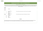
Weight Controller
HI-3030
USER GUIDE
Local Field Service
Hardy has over 200 field technicians in the U.S., and more positioned throughout the world to assist you in your support needs. We also have factory engineers who will travel to your facility anywhere in the world to help you solve
challenging applications. We're ready to support you with:
•
•
•
•
Installation and start-up
Routine maintenance and certification
Plant audits and performance measurement
Emergency troubleshooting and repair
To request Emergency Service and Troubleshooting, Start-up, Installation, Calibration, Verification or to discuss a
Maintenance Agreement please call 800-821-5831 or Emergency Service after hours (Standard Hours 6:00 AM to
6:00 PM Pacific Standard Time) and weekends Ext. 9550.
Outside the U.S
Hardy Process Solutions has built a network of support throughout the globe. For specific field service options available in your area please contact your local sales agent or our U.S. factory at +1 858-292-2710.
i
Table of Contents
Table of Contents
Table of Contents
- - - - - - - - - - - - - - - - - - - - - - - - - - - - - - - - - - - - - - -i
Table of Illustrations
- - - - - - - - - - - - - - - - - - - - - - - - - - - - - - - - - - - - - - -I
Chapter 1
Overview - - - - - - - - - - - - - - - - - - - - - - - - - - General Introduction to the Hardy Weight Controller HI 3030
User Guide - - - - - - - - - - - - - - - - - - - - - - - - - Description - - - - - - - - - - - - - - - - - - - - - - - - - - Typical Applications - - - - - - - - - - - - - - - - - - - - - Connectivity - - - - - - - - - - - - - - - - - - - - - - - - - Mapped I/O - - - - - - - - - - - - - - - - - - - - - - - - - - WAVERSAVER® - - - - - - - - - - - - - - - - - - - - - - C2® Calibration - - - - - - - - - - - - - - - - - - - - - - - - On-Board Diagnostics - - - - - - - - - - - - - - - - - - - - - INTEGRATED TECHNICIAN® - - - - - - - - - - - - - - - Secure Memory Module (SMM) - - - - - - - - - - - - - - - - Set Point Relays - - - - - - - - - - - - - - - - - - - - - - - Serial Port - - - - - - - - - - - - - - - - - - - - - - - - - - Options - - - - - - - - - - - - - - - - - - - - - - - - - - - - -JB - - - - - - - - - - - - - - - - - - - - - - - - - - - - HI 3000-RC - - - - - - - - - - - - - - - - - - - - - - - -PB - - - - - - - - - - - - - - - - - - - - - - - - - - - -AC, -AA, -AO - - - - - - - - - - - - - - - - - - - - - - -DC, -DD, -DA - - - - - - - - - - - - - - - - - - - - - - -RIO - - - - - - - - - - - - - - - - - - - - - - - - - - - -MB - - - - - - - - - - - - - - - - - - - - - - - - - - - -CN - - - - - - - - - - - - - - - - - - - - - - - - - - - -LC - - - - - - - - - - - - - - - - - - - - - - - - - - - -2S - - - - - - - - - - - - - - - - - - - - - - - - - - - - -4S - - - - - - - - - - - - - - - - - - - - - - - - - - - - -DN - - - - - - - - - - - - - - - - - - - - - - - - - - - -ROC - - - - - - - - - - - - - - - - - - - - - - - - - - -NTEP - - - - - - - - - - - - - - - - - - - - - - - - - - -CWM - - - - - - - - - - - - - - - - - - - - - - - - - - Communication Options - - - - - - - - - - - - - - - - - DeviceNet - - - - - - - - - - - - - - - - - - - - - - EtherNet/IP™ - - - - - - - - - - - - - - - - - - - - Analog Output - - - - - - - - - - - - - - - - - - - - MOD-Bus/TPC/IP - - - - - - - - - - - - - - - - - - OPC - - - - - - - - - - - - - - - - - - - - - - - - - Remote I/O (RIO) Interface to the Allen Bradley Network
Profibus - - - - - - - - - - - - - - - - - - - - - - - -
-
-
-
-
-
-1
-1
-2
-3
-3
-3
-3
-3
-3
-3
-4
-4
-4
-4
-4
-4
-4
-4
-4
-4
-4
-4
-4
-4
-4
-4
-4
-4
-5
-5
-5
-5
-5
-5
-5
-5
Chapter 2
Calibration - - - - - - - - - - - - - - Getting Started - - - - - - - - - - - - - Binding - - - - - - - - - - - - - - Electrical Check Procedures - - - - - C2 Quick Calibration From the Front Panel C2 Quick Calibration From the Web Page -
-
-
-
-
-
-7
-7
-7
-7
-7
-9
Chapter 3
Operating Procedures - - - - - - - - - - - - - - - - - - - - - - - - - - - 11
About Chapter 3 - - - - - - - - - - - - - - - - - - - - - - - - - - - - - - 11
Getting Started - - - - - - - - - - - - - - - - - - - - - - - - - - - - - - - 11
-
-
-
-
-
-
-
-
-
-
-
- - - - - -1
HI 3030 Weight Controller
User Guide
Help - - - - - - - - - - - - - - - - - - - - - - - - About Help - - - - - - - - - - - - - - - - - - - Operating the Weight Controller from the Front Panel - Front Panel Display - - - - - - - - - - - - - - - Button Functions - - - - - - - - - - - - - - - - Tare Button - - - - - - - - - - - - - - - - - Zero Button - - - - - - - - - - - - - - - - - Help Button - - - - - - - - - - - - - - - - - Display Button - - - - - - - - - - - - - - - Print Button - - - - - - - - - - - - - - - - - Up/Down - Left/Right Buttons - - - - - - - - Enter Button - - - - - - - - - - - - - - - - Exit Button - - - - - - - - - - - - - - - - - Clear Button - - - - - - - - - - - - - - - - 1 Button - - - - - - - - - - - - - - - - - - 2/ABC Button - - - - - - - - - - - - - - - Setup/3/DEF Button - - - - - - - - - - - - - Amount/4/GHI - - - - - - - - - - - - - - - Units/5/JKL Button - - - - - - - - - - - - - 6/MNO Button - - - - - - - - - - - - - - - Tare Val/7/PQRS Button - - - - - - - - - - 8/TUV Button - - - - - - - - - - - - - - - Test/9/WXYZ Button - - - - - - - - - - - - User/./-/_/@ Button - - - - - - - - - - - - - 0/Char. Button - - - - - - - - - - - - - - - Starting Up for the First Time - - - - - - - - - - - - Set Points - - - - - - - - - - - - - - - - - - - - - - About Set Points - - - - - - - - - - - - - - - - Set Point Limits - - - - - - - - - - - - - - - - - Dead Band Limits - - - - - - - - - - - - - - Three General Rules for Setpoints - - - - - - Preact Limits - - - - - - - - - - - - - - - - Entering Set Points from the Front Panel - - - - - About the Adjust Set Point Menu - - - - - - - - - Entering Set Points Procedure - - - - - - - - Entering Set Points from the Web Browser - - - - About the Adjust Set Point Menu - - - - - - - - - Rate of Change Option (-ROC) - - - - - - - - - - - - Viewing Rate of Change from the Front Panel - - Viewing the Rate of Change from the Web Browser Viewing the NTEP Audit Trail - - - - - - - - - - - - Software Downloads for Your HI 3030 - - - - - - - - Index
-
-
-
-
-
-
-
-
-
-
11
11
11
11
11
11
11
12
12
12
12
12
12
12
12
12
13
13
13
13
13
13
13
13
13
13
14
14
14
14
14
14
15
15
15
16
16
18
18
18
19
20
ii
I
Table of Illustrations
Table of Illustrations
Chapter 1
Overview
- - - - - - - - - - - - - - - - - - - - - - - - - - - - - - - - -1
FIG. 1-1 FILLING A VESSEL USING A FEEDER - - - - - - FIG. 1-2 SEQUENTIAL BATCH CONTROL - - - - - - - - FIG. 1-3 LEVEL MONITORING - - - - - - - - - - - - - - FIG. 1-4 DISPENSING (LOSS-IN-WEIGHT) FROM A VESSEL
TO ANOTHER VESSEL - - - - - - - - - - - - - Chapter 2
Calibration
FIG. 2-1
FIG. 2-2
FIG. 2-3
FIG. 2-4
FIG. 2-5
FIG. 2-6
FIG. 2-7
FIG. 2-8
FIG. 2-9
FIG. 2-10
FIG. 2-11
Chapter 3
- - - - - -2
- - - - - -2
- - - - - -2
- - - - - -3
- - - - - - - - - - - - - - - - - - - - - - - - - - - - - - - -7
PROPERLY INSTALLED LOAD CELL WITH NO BINDING
MAIN MENU - - - - - - - - - - - - - - - - - - - - - - - CONFIGURATION MENU/SELECTING CALIBRATION - CALIBRATION MENU/C2 CAL - - - - - - - - - - - - - - C2 CALIBRATION/CHANNEL 1 SUB-MENU - - - - - - - ENTERING THE REFERENCE POINT - - - - - - - - - - C2 CALIBRATION - - - - - - - - - - - - - - - - - - - - CONFIGURATION MENU/SELECTING SETUP - - - - - - CONFIGURATION PAGE - - - - - - - - - - - - - - - - - CALIBRATION SUB-MENU - - - - - - - - - - - - - - - CAL COMPLETED OK - - - - - - - - - - - - - - - - - - -
-
-7
-7
-8
-8
-8
-8
-8
-9
-9
-9
-9
Operating Procedures - - - - - - - - - - - - - - - - - - - - - - - - - - - 11
FIG. 3-1
FIG. 3-2
FIG. 3-3
FIG. 3-4
FIG. 3-5
FIG. 3-6
FIG. 3-7
FIG. 3-8
FIG. 3-9
FIG. 3-10
FIG. 3-11
FIG. 3-12
FIG. 3-13
FIG. 3-14
FIG. 3-15
FIG. 3-16
FIG. 3-17
FIG. 3-18
FIG. 3-19
FIG. 3-20
FIG. 3-21
FIG. 3-22
FIG. 3-23
FIG. 3-24
FIG. 3-25
FIG. 3-26
FRONT PANEL - - - - - - - - - - - - - - - - - - - - - DIRECTIONAL BUTTONS - - - - - - - - - - - - - - - LIST SELECTION/ENTER BUTTON - - - - - - - - - - SUMMARY DISPLAY/1 CHANNEL - - - - - - - - - - - SUMMARY DISPLAY/2 CHANNEL - - - - - - - - - - - SUMMARY DISPLAY/4 CHANNELS - - - - - - - - - - SINGLE CHANNEL SELECTION DISPLAY - - - - - - - TARE MENU - - - - - - - - - - - - - - - - - - - - - - TARE MENU/ENTRY ACCEPTED - - - - - - - - - - - LOW AND HIGH PREACT TRIP LIMITS - - - - - - - - CONFIGURATION MENU/SELECTING ADJUST
SETPOINTS - - - - - - - - - - - - - - - - - - - - - - SETPOINTS MENU/CHOOSE SETPOINT - - - - - - - - ADJUST SETPOINT # MENU - - - - - - - - - - - - - - ADJUST SETPOINT MENU/SETTING PREACT - - - - - ADJUST SETPOINT MENU/SETTING DEAD BAND - - ADJUST SETPOINT MENU/SRC: NOT MAPPED - - - - HI 3030 WEIGHT CONTROLLER
HOME PAGE/SELECTING CONFIGURATION - - - - CONFIGURATION PAGE/ SELECTING ADJUST
SETPOINT - - - - - - - - - - - - - - - - - - - - - - ADJUST SETPOINT PAGE/SELECTING SETPOINT # - ADJUST SETPOINT PAGE/SELECTING WEIGHT INPUT
ADJUST SETPOINT PAGE/SELECTING RELAY
OUTPUT - - - - - - - - - - - - - - - - - - - - - - - ADJUST SETPOINT PAGE/SAVING SETPOINT
ENTRIES - - - - - - - - - - - - - - - - - - - - - - - ADJUST SETPOINT PAGE/NEW MAPPING DISPLAYED
MAIN MENU - - - - - - - - - - - - - - - - - - - - - - RATE OF CHANGE READING - - - - - - - - - - - - - HI 3030 HOME PAGE/SELECTING OPERATION - - - - -
-
-
- 11
- 12
- 12
- 13
- 13
- 13
- 14
- 14
- 14
- 14
-
-
- 15
- 15
- 15
- 15
- 15
- 16
- - - 16
- - - 16
- - - 17
- - - 17
- - - 17
-
-
- 17
- 18
- 18
- 18
- 18
HI 3030 Weight Controller
User Guide
FIG. 3-27 OPERATION/SELECTING MONITOR - - - - - FIG. 3-28 RESETTING RATE OF CHANGE - - - - - - - FIG. 3-29 HI 3030 WEB PAGE/SELECTING OPERATION FIG. 3-30 OPERATION PAGE/SELECTING DIAGNOSTICS
FIG. 3-31 OPERATION - DIAGNOSTICS PAGE - - - - - FIG. 3-32 SELECTING STATUS LOG - - - - - - - - - - FIG. 3-33 NTEP AUDIT TRAIL - - - - - - - - - - - - - - FIG. 3-34 3000 SERIES DOWNLOAD LINK - - - - - - - FIG. 3-35 3000 SERIES DOWNLOAD PAGE - - - - - - - -
-
-
-
-
-
-
-
18
18
19
19
19
19
19
20
20
II
1
CHAPTER 1
Overview
CHAPTER 1: OVERVIEW
General Introduction to the Hardy Weight
Controller HI 3030 User Guide
mounted with no display. A remote 6 digit, 7 segment LED
display is available as an option for the HI 3030R.
This User Guide provides the User with a complete description of the operating procedures for the HI 3030 Weight
Controller. To get the maximum service life from this product, operators should use this instrument in accordance with
recommended practices either implied or expressed in this
manual. Before using the Weight Controller all operators
should read and understand all cautions, warnings, and
safety procedures, referenced or explicitly stated in this manual, to insure the safe operation of this instrument. Hardy
Process Solutions sincerely appreciates your business. We
encourage input about the performance and operation of our
products from our customers. Should you not understand any
information in this manual or experience any problems with
this product, please contact our Technical Support Department at:
The HI 3030 Weight Controller is designed with output
alarms, for example:
•
•
•
The HI 3030 Weight Controller is a stand-alone controller:
•
•
Phone: (858) 278-2900
FAX: (858) 278-6700
E-Mail:
•
•
[email protected]
[email protected]
Or visit our web site at:
http://www.hardysolutions.com
Our web site is full of useful information about our products,
process weighing and vibration analysis applications. You
can also update the HI 3030 Weight Controller Manual. The
latest revised manuals are available FREE in the Support
Section of our Web Site. While you’re on the site feel free to
visit the other web pages which can provide answers to your
questions about, filling/dispensing, load points, process
weighing, vibration analysis or other Hardy instruments. Be
sure to sign up for the Hardy Newsletter to get the latest
information on all Hardy products and services. For answers
to technical issues and service problems check the Hardy
Web Tech on our Hardy Web Site. Most problems can be
resolved by the Hardy Web Tech, 24 hours a day 7 days a
week. You can still contact a technician by phone during our
operating hours if necessary.
Description
The Hardy HI 3030 is a 4 channel Weight Controller which
is part of a complete line of application specific process
weighing instruments. The Weight Controller is available as
an HI 3030, a stand alone weight controller with a backlit
LCD display (4 lines; 20 characters) and key pad or an HI
3030R, blind remote stand-alone weight controller, swivel
Weight zeroed is greater than zero-tolerance value
Exceeds motion tolerance, cannot zero
scale
Exceeds motion tolerance, cannot tare
scale.
•
WAVERSAVER® - Eliminates the effects
of vibration on the scale.
C2® Electronic Calibration - Calibration
without test weights.
SMM (Secure Memory Module) - Memory for manual transfer of configuration
data to another HI 3030 instrument(s).
All of Hardy’s 3000 Series instrumentation is loaded with
standard features like a selectable 10/100 BaseT Ethernet
port and an embedded web server (Hardy Control-Link Network) to link performance diagnostics and setup data to and
from your local Intranet, Extranet, VPN or via the Internet
(World Wide Web). An optional Devicenet interface allows
multiple applications to be viewed and controlled from one
display and allows 3rd party I/O to be easily added to the
system. Mapped I/O saves you wiring costs by distributing
the I/O where you need it at the process or in the control
room. The controllers act as “Masters” over Ethernet and
optional Devicenet communications while optional interfaces for Allen-Bradley Remote I/O, Profibus and Analog
provide communications to PLC® and DCS systems. The
ControlNet option provides real-time, rapid integration of
complex batch control systems, and systems with multiple
controllers and networks.
Hard copy records can be printed via a standard 232 simplex
printer port to an external printer.
NOTE:
PLC® is a registered trademark of the AllenBradley Corporation.
The HI 3030’s INTEGRATED TECHNICIAN®, in conjunction with an IT Junction Box, provides built-in system diagnostics that allow you to troubleshoot and diagnose your
weighing system right from the front panel or web browser.
You can read individual load sensor voltages and weights,
HI 3030 Weight Controller
User Guide
make comparisons, and isolate individual system components for quick and easy troubleshooting.
Typical Applications
•
•
•
•
Liquid
Filling a Vessel Using a Feeder - Filling is
the adding (gain-in-weight) of a material
into a container on a scale. (See Fig. 1-1)
Sequential Batch Control - A gain-inweight application where multiple ingredients are added one at a time into a single
weight hopper. (See Fig. 1-2)
Level Monitoring - Maintaining material
levels in various vessels.
Dispensing A Vessel - Dispensing is the
adding of a material by (loss-in-weight)
from a vessel on a scale to a container
which is off the scale. (See Fig. 1-4)
Dry
Powder
Granular
Feeder
Elevator
Auger
Bulk
Load
Cells
Weighing
Instrument
D is ch a r g e
R e lay
Mixer
Discharge
Gate
Refill
Gate
FIG. 1-2 SEQUENTIAL BATCH CONTROL
High Level (Prox)
Feeder
(Fast & Slow Speed)
Low Level (Prox)
Scale
Load Points
FIG. 1-1 FILLING A VESSEL USING A FEEDER
FIG. 1-3 LEVEL MONITORING
2
3
CHAPTER 1
Overview
Load Point
Load Point
actual weight data. WAVERSAVER® can be configured
from the front panel to ignore noise with frequencies as low
as 0.25 Hz. One of four higher additional cut off frequencies
may be selected to provide a faster instrument response time.
The default factory configuration is 0.50 Hz vibration frequency immunity.
C2® Calibration
Dispense Gate
Target Weight
Discharge Gate
FIG. 1-4 DISPENSING (LOSS-IN-WEIGHT) FROM A
VESSEL TO ANOTHER VESSEL
Connectivity
All HI 3000 Series products enable the operator to use the
selectable 10/100 base T Ethernet port and its embedded web
server to link performance, diagnostics and setup data to and
from your intranet, extranet, VPN or the internet. Receive
alarms via e-mail or over WAP enabled devices including
cellular phones and PDAs. An optional ControlNet interface
allows multiple applications to be viewed from a display.
The optional DeviceNet interface allows multiple applications to be viewed and controlled from a display and additional 3rd party I/O to be easily added to a system. The
controller has a single RS-232 serial port configured as a
printer port.
Mapped I/O
Mapped I/O saves wiring costs by distributing the I/O where
you need it, at the process or in the control room. The controller is a DeviceNet Scanner and the DeviceNet Scan table
is configured using RS NetWorx®. Optional interfaces for
Allen-Bradley Remote I/O, Profibus and Analog provide
communications to PLC and DCS systems.
WAVERSAVER®
Typically, mechanical noise (from other machinery in a plant
environment) is present in forces larger than the weight
forces trying to be detected. The HI 3030 is fitted with
WAVERSAVER® technology which eliminates the effects of
vibratory forces present in all industrial weight control and
measurement applications. By eliminating the factor of
vibratory forces the controller is capable of identifying the
C2® Second Generation Calibration enables a scale system
to be calibrated electronically without using certified test
weights which equals the system’s load capacity. A C2
weighing system consists of up to eight load sensors, a junction box, interconnect cable and an instrument with C2 capabilities, such as the Filler/Dispenser/IBC or Weight
Controller. All Hardy C2 certified load sensors contain digital information detailing its unique performance characteristics. The Hardy HI 3030 Weight Controller reads the
performance characteristics of each individual load sensor
and detects the quantity of load sensors in the system. Calibration is performed by simply adding a reference point from
the front panel or via the Web Server. The reference can be
zero (no weight on the scale) or alternatively, a known
weight on the scale. The instrument is capable of performing
traditional calibration such as with the use of certified test
weights.
NOTE:
WAVERSAVER® and C2® are registered trademarks of Hardy Process Solutions Inc.
On-Board Diagnostics
The HI 3030 has a built in diagnostics utility which enables
the operator to rapidly troubleshoot a weighing system from
the front panel of the controller or via the Web Server. Simply press the Test button and scroll through several tests that
will furnish the current state of each of the parameters that
concern your application and the weigh system. Help is just
a click away in the event you should not understand the
information on the display or need a description of the
parameter.
INTEGRATED TECHNICIAN®
HI 3000 Series INTEGRATED TECHNICIAN™ (IT®) in
conjunction with an IT junction box provides built-in System
diagnostics that makes it possible to diagnose weighing system problems from the front panel or Web Interface. IT reads
individual load sensor voltages and weights for each channel
and isolates individual system components for quick and
easy troubleshooting.
Secure Memory Module (SMM)
The Secure Memory Module stores critical configuration (up
to 12 set points), calibration and setup data of the HI 3030
Weight Controller, thereby protecting this information from
corruption. During system operation when a new parameter
HI 3030 Weight Controller
User Guide
is entered, the SMM automatically updates the value in its
memory. Data stored in one HI 3030 can be restored in
another HI 3030 by physically transferring the SMM to the
new instrument. The SMM is conveniently accessible from
the instruments rear panel.
Set Point Relays
The HI 3030 is fitted with four (4) optional internal selectable, Form A mechanical (SPST) relays which are mappable
to 12 set points each with its own deadband and preact. The
relays can be used to open or close valves or gates, turn on/
off motors, mixers, vibration equipment, heaters or coolers
to name a few. The user can select either AC or DC relays.
Serial Port
One standard RS 232 serial port which can be configured to
receive commands and transmit weight data to a serial
printer. Baud rates are user selectable at 600, 1200, 2400,
4800, 9600 or 19,200.
4
-MB
Stainless steel wall mount swivel bracket/stand for wall or
desk top mounting.
-CN
ControlNet enables multiple controllers to control I/O on the
same wire and permits multicast of both inputs and peer-topeer data, reducing traffic on the wire and increasing system
performance.
-LC
Single Scale, Single Loadcell or summed LoadAll input.
-2S
Dual Scale Input
-4S
Options
Four Scale Input
-JB
-DN
Enables a single channel instrument to sum four load sensor
inputs to act as a built-in summing box.
DeviceNet is a low-level network designed to connect the
Hardy HI 3000 Series instruments to higher-level controllers
such as PCs, PLCs, or embedded controllers.
HI 3000-RC
Rear cap for the HI 3000 Series controllers. Upgrades the
entire assembly to a NEMA 4X rating by enclosing all the
rear panel connectors.
-PB
Profibus interface allows full instrument capabilities to be
communicated remotely to and from a Siemens or other Profibus compatible processor.
-AC, -AA, -AO
AC input power for the HI 3030, without relays, with AC
relays or with DC relays.
-DC, -DD, -DA
DC input power for the HI 3030, without relays, with AC
relays or with DC relays.
-RIO
Allen-Bradley Remote I/O interface allows full instrument
capabilities to be communicated remotely to and from an
Allen-Bradley processor.
-ROC
The ROC option measures and displays the rate at which a
material enters or is dispensed from the scale over a period
of time. To develop ROC data, a register is used that is 55
entries in length. New weight values are inputted to the register at the rate of 1/55th of the time base. The first register is
subtracted from the 55th Register. The 55th register is one
time base older than the 1st register. The time frame can be
set to units per second, minute or hour. A time base of discrete values is selectable from 1 to 1800.
-NTEP
The HI 3030 is approved for National Institute of Standards
and Technology (NIST) applications formally called the
National Bureau of Standards (NBS), and certified under the
National Type Evaluation Program (NTEP) for up to 10,000
counts when the NIST mode is activated. This option is
required when products are to be directly sold based on
weight readings of the scale. It is not available on the blind
remote version. For price, availability and installation
instructions, please contact your local Hardy Representative
or the Hardy Service Center.
NOTE:
The NTEP Option requires the HI 3030 Firmware
version 2.8.00.00 or above.
5
CHAPTER 1
Overview
-CWM
The HI 3030 is approved for Measurement Canada, Canada
Weights and Measures Class III / III HD (3000 d). This
option is required when products are to be directly sold
based on weight readings of the scale. It is not available on
the blind remote version.
Communication Options
NOTE:
For Installation, Configuration and Setup please
refer to the HI 3000 Operation and Installation
Manual, Cabling and Networks Sections.
DeviceNet
The DeviceNet Network is an open, global industry-standard
communication network designed to provide an interface
through a single cable from a programmable controller or PC
directly to all HI 3000 Series instruments as well as smart
devices such as sensors, push buttons, motor starters, simple
operator interfaces, drives and other weigh modules.
EtherNet/IP™
EtherNet/IP, short for Ethernet Industrial Protocol, is an
open industrial networking standard that takes advantage of
commercial, off-the-shelf Ethernet communication chips and
media. Ethernet technology, enables the user to access
device-level data from the Internet.The Ethernet/IP networking standard supports both implicit messaging (real-time I/O
messaging) and explicit messaging (message exchange).
EtherNet/IP is an open network that takes advantage of commercial technology that already exists.
TCP/IP is the transport and network layer protocol of the
Internet and is commonly linked with all Ethernet installations and the business world. TCP/IP provides a set of services that any two devices can use to share data. Because
Ethernet technology and standard protocol suites such as
TCP/IP have been published for public use, standardized
software tools and physical media have been mass-produced
and are readily available, offering you the benefits of known
technology and accessibility. The UDP/IP (User Datagram
Protocol) is also used in conjunction with the Ethernet network. UDP/IP provides fast, efficient data transport required
for real-time data exchange.
Analog Output
The Analog Output Option enables the transmission of
Gross, Net, or Total weight as 0-5 VDC, 0-10 VDC, 0-20
mA or 4-20 mA (or the reverse of these), and makes it possible to span these ranges over a portion of the weight data.
Two analog option boards can be installed in each instrument. both voltage and current data are available simultaneously.
MOD-Bus/TPC/IP
TCP/IP is the common transport protocol of the Internet and
is actually a set of layered protocols, providing a reliable
data transport mechanism between machines. Ethernet has
become the de facto standard of corporate enterprise systems
and it has also become the de facto standard for factory networking. Ethernet has matured to the point that the cost of
implementing this network solution has been dropping to
where its cost is commensurate with those of today's fieldbuses. Using Ethernet TCP/IP in the factory allows true integration with the corporate Intranet and MES systems that
support your factory.
OPC
OLE for Process Control (OPC) enables an HI 3000 module
to communicate with any device that supports OLE/COM.
The architecture is designed to utilize the Microsoft distributed OLE technology (DCOM) to facilitate clients interfacing to remote servers.
Remote I/O (RIO) Interface to the Allen Bradley Network
The RIO port allows bi-directional communications with
Allen-Bradley Programmable Logic Controllers (PLC) and
Small Logic Controllers (SLC). The HI 3010 represents a
selectable 1/4, 1/2, 3/4 or full rack of discrete I/O (32 bits in
the Logic Controllers output and input image files) to the
PLC Controller and supports both discrete and block transfers of data. It can support up to 230.4 Kbaud transfer rates.
Profibus
Allows bi-directional communications to Profibus (Process
Fieldbus) products including those made by Siemens, GE
Fanuc and Texas Instruments. This interface supports PROFIBUS-DP (Decentralized Periphery) and processes both
Selectable Predetermined and Block transfer commands. It
supports up to 12 Mbaud transfer rates.
HI 3030 Weight Controller
User Guide
6
11
CHAPTER 3
Filler
CHAPTER 3: OPERATING PROCEDURES
About Chapter 3
Chapter 3 contains step-by-step instructions for operating the
Hardy HI 3030 Weight Controller. The procedures include
complete instructions for operating the Weight Controller
from the Front Panel, ControlNet (optional), DeviceNet
(optional) and Remote I/O (optional) Web Browser. We
highly recommend reading the procedures before operating
the Weight Controller. Being familiar with the operating procedures insures that the Controller will provide trouble free
service.
NOTE:
Operating the Weight Controller from the
Front Panel
Installation, and configuration for ControlNet,
DeviceNet and Remote I/O can be found in the HI
3000 Operation and Installation Manual.
Getting Started
Before operating the Hardy HI 3030 Weight Controller,
check to make sure the following procedures have been performed:
•
•
•
Power and Load Point cables properly
installed.
Communication cables properly installed.
Calibration Performed.
All the features of the Weight Controller operate the same no
matter what the interface. First let’s get familiar with operating the HI 3030 from the front panel of the instrument. (See
Fig. 3-1)
FIG. 3-1 FRONT PANEL
Front Panel Display
The Front Panel Display is a 4 line x 20 Alphanumeric character LCD. The screen displays all the menus for Configuring, Calibrating and Operating the HI 3030 Weight
Controller.
Button Functions
Tare Button
Help
About Help
As you move through the setup/configuration menus you
may on occasion need assistance. If you need help, do the
following:
Step 1. Use the up and down arrows to move the cursor in
front of the Menu Item you want help on.
Step 2. Click the Help button either on the front Panel and a
Help Dialog appears. The help dialog tells you what
the Menu Item is used for or other descriptive information to help you enter the right parameters for the
current menu item.
Step 3. Push the Exit button to return to the current menu.
Tares the selected scale. The Tare button sets the Tare
Weight equal to the Gross Weight and makes the Net Weight
equal to 0. When you are in Net Mode (i.e. a channel displays NET in the Summary display, you will see the weight
change to 0.00. If you are in Gross mode you will not see
anything happen, but the Net weight is changed to 0.00.
Press the right or left arrow buttons to verify that the Net
weight is 0.00.
Zero Button
Used in Gross mode to zero the selected scale to within the
tolerance level.
•
This function can be used as many times
as desired as long as the total does not
exceed the value entered as the zero tolerance.
HI 3030 Weight Controller
User Guide
12
Help Button
The Help button displays a Help message for the current
Menu item (the Menu item in front of the cursor) that is displayed.
Display Button
The Display Button displays the Net, Gross and Tare weights
of the scale that is connected to the Channel which is
selected in the Summary Display. To select a Channel move
the cursor in front of that channel then press the Display button. There are 4 channels total. To sequentially cycle through
all the channels, continue to press the Display button.
Print Button
The Print Button when pressed prints the Gross, Net and
Tare weights to an attached printer. If the Scoreboard is activated the Print Button does not function.
Up/Down - Left/Right Buttons
FIG. 3-3 LIST SELECTION/ENTER BUTTON
For example, when selecting units from a pick list, use the
left and right arrows to move the cursor in front of the unit
you want and press the Enter button.
Exit Button
Takes you back to the previous menu.
Clear Button
The Clear button clears the total Alpha/Numeric Entry and
repositions the cursor for the first entry.
1 Button
Enters the integer 1 in a display.
2/ABC Button
Enters the integer 2 in the display. Also enters the characters
A, B, C. Pushing the button once enters the integer 2.
FIG. 3-2 DIRECTIONAL BUTTONS
The Up/Down arrow buttons move the cursor vertically
allowing the user to scroll through each item of a menu. The
Left/Right arrow buttons move the cursor horizontally left
and right. The Left arrow button has an added backspace
function. For example if there are Alpha/Numeric characters
that appear in the display, as you press the left button it
erases the characters. The Right arrow button moves the cursor to the right in the display and does not erase a alphanumeric entry. The Left/Right arrow buttons also move the
cursor through a pick list. (See Fig. 3-3)
Enter Button
The Enter button enters the Alpha/Numeric value entered for
a menu item in the display. The Enter button also enters the
selections from a pick list.
NOTE:
For numeric entries only: Push the button and
the number on the button is entered.
NOTE:
For Alphanumeric entries only: Pushing the button once, the first letter on the button is entered in
uppercase, A, D, G, and so on. Push the button a
second time, the second letter is entered in uppercase, B, E, H, K and so on. Push the button a
third time, the third letter is entered in uppercase,
C, F, I, L, and so on. Push the button a fourth
time, the fourth letter is entered in uppercase, S,
Z. Push the button a fifth time the first letter is
entered in lowercase, a, d, g, and so on. After you
go through the lowercase letters, you can push
the button again for the number. You need to push
the buttons rapidly. If you delay too long the
instrument will accept the alphanumeric character and move the cursor to the left preparing for
the next alphanumeric entry. This is true for all
the Alphanumeric buttons. If this occurs use the
left arrow button to erase the current entry and
enter another.
13
CHAPTER 3
Filler
Setup/3/DEF Button
This enables you to access the configuration and setup
menus. Also enters the number 3 and the letters D, E, F.
Amount/4/GHI
Enables you to make quick set point changes. Also enters the
number 4 and the letters C, H, I.
Units/5/JKL Button
Enables you to change the units of measure (Lbs/Kg/oz/g)
while in the standby mode of operation. Also enters the integer 5 and the letters J, K, L.
Starting Up for the First Time
When the HI 3030 Weight Controller powers up after delivery from the factory, a Summary display appears with the
correct number of channels for the installed Channel card in
your instrument.
Step 1. The First display is the Summary Display with
either one, two or four channels (depending on the
installed option card) displaying the weight in
Gross mode. (See Fig. 3-4, 3-5, 3-6)
Step 2. To change from Gross to Net mode press either the
right or left arrow buttons until NET appears.
6/MNO Button
Enters the integer 6 and the letters M, N, O.
Tare Val/7/PQRS Button
Enables you to set the Tare Value. Also enters the integer 7
and letters P, Q, R, S.
FIG. 3-4 SUMMARY DISPLAY/1 CHANNEL
8/TUV Button
Enters the integer 8 and the letters T, U, V.
Test/9/WXYZ Button
Enables you to enter the Self-Test and IT modes. Also enters
the inter 9 and letters W, X, Y, Z.
FIG. 3-5 SUMMARY DISPLAY/2 CHANNEL
User/./-/_/@ Button
Enables you to enter or change the 3 digit user code while in
the standby mode. Also enters the period (.), dash (-),underscore (_) and @ symbols.
NOTE:
The dash is also used when entering negative
numbers. Before entering a negative number
press the User/./-/_/@ button two times.
0/Char. Button
Enters the integer 0 in the display. When you push the button
the second time a set of characters appears in the display.
Step 1. Using the up and down arrow buttons move the cursor in front of the character you want to display.
Step 2. Press the Enter Button to select the character.
Step 3. Press the Exit Button to return to the display. The
character should now appear next to the cursor.
FIG. 3-6 SUMMARY DISPLAY/4 CHANNELS
Step 3. To select a channel, press the up or down buttons to
move the cursor in front of the channel you want.
(See Fig. 3-6)
Step 4. Press either the Display or the Enter button. The
Single Channel display appears for the selected
channel. (See Fig. 3-7)
HI 3030 Weight Controller
User Guide
14
Set Point Limits
Dead Band Limits
•
•
FIG. 3-7 SINGLE CHANNEL SELECTION DISPLAY
Step 5. You will notice an arrow at the end of the TARE
line. (See Fig. 3-7)
Step 6. To change the Tare Weight, press the Enter button.
The Tare menu appears. (See Fig. 3-8)
The dead band value can be set as a positive or negative value. It is used to prevent
relay chatter once the set point is reached.
For example: if a set point value was 1000
pounds and the dead band was set to -5
pounds, the relay would close at a 1000
pounds but not open until the weight
dropped to 995 pounds. This would be
used if a set point is a high trip limit. A
positive dead band would be used for a
low trip limit. Examples are shown for
Low and High Trip Limits. (See Fig. 310) Using a set point of 1,000 pounds and
a dead band of -800 pounds will cause the
level to remain between 200 and 1,000
pounds.
Three General Rules for Setpoints
1.
FIG. 3-8 TARE MENU
2.
Step 7. To change the Tare weight:
3.
•
•
•
•
Press the Clear button.
Use the Alpha Numeric pad to enter the
new Tare weight.
Press the Enter button to set the entry.
A brief “Entry Accepted” displays. (See
Fig. 3-9)
Set points activate at the set point plus
the preact.
Set points deactivate at the set point
plus the deadband.
The deadband should be numerically
larger than the preact to prevent relay
chatter.
FIG. 3-9 TARE MENU/ENTRY ACCEPTED
Step 8. Press the Exit button to return to the Single Channel
Display.
Step 9. Press the Exit button again to return to the Summary Display.
Set Points
About Set Points
FIG. 3-10 LOW AND HIGH PREACT TRIP LIMITS
Preact Limits
The set point value is the target weight or level. It may be set
in either net or gross weight units.
•
The preact value is the number of units
below (negative value) or above (positive
15
CHAPTER 3
Filler
•
value) the set point value at which the
relay will trip.
It is used as an “in-flight” compensation
value when filling a vessel. If set to zero,
there will be no compensation.
Entering Set Points from the Front Panel
ADJUSTSETPOINT 2
0.00
Pr eact :
0.00
Deadbd
0.00
>Amt Req:
About the Adjust Set Point Menu
•
•
NOTE:
Used to enter the Amount Required (Amt
Req), Dead Band and Preact values.
Used to enter the associated values for the
optional, internal relays when installed.
To scroll forward or backward through the Set
Point Menus, press the Up or Down arrow buttons.
Entering Set Points Procedure
Step 1. Press the Setup/3 button. The Configuration Menu
appears. (See Fig. 3-11)
FIG. 3-13 ADJUST SETPOINT # MENU
Step 5. To enter a new Amount Required value, use the
alphanumeric buttons to enter the desired Amount
Required value. Should you make a mistake, press
the Clr button and begin again.
•
•
To enter a negative number, first press the
User/./-/_/@ button two times.
Now use the alphanumeric key pad to
enter the number.
Step 6. Press the Enter button. The controller indicates
“entry accepted”.
Step 7. Press the down arrow button until the cursor is in
front of Preact. (See Fig. 3-14)
ADJUSTSETPOINT 2
Amt Req:
0.00
>Pr eact :
0.00
Deadbd
0.00
FIG. 3-11 CONFIGURATION MENU/SELECTING
ADJUST SETPOINTS
Step 2. Press the Enter button. The Setpoints Menu
appears. (See Fig. 3-12)
FIG. 3-14 ADJUST SETPOINT MENU/SETTING
PREACT
Step 8. To enter a new Preact value, use the alphanumeric
buttons to enter the desired Amount Required
value. Should you make a mistake, press the Clr
button and begin again.
Step 9. Press the Enter button to set the entry. The controller indicates “entry accepted”.
Step 10. Press the down arrow until the cursor is in front of
Deadbeat (Dead Band). (See Fig. 3-15)
FIG. 3-12 SETPOINTS MENU/CHOOSE SETPOINT
Step 3. There are 12 setpoints. Press on the left or right
arrow buttons to select the setpoint you want to
adjust. The right arrow button moves up the list.
The left arrow button moves down the list.
Step 4. Press the Enter button. The Adjust Setpoint Menu
for the set point number you selected appears. (See
Fig. 3-13)
ADJUSTSETPOINT 2
Pr eact :
0.00
>Dead Bd
0.00
Sr c:
Not Mapped
FIG. 3-15 ADJUST SETPOINT MENU/SETTING
DEAD BAND
HI 3030 Weight Controller
User Guide
16
Step 11. To enter a new Deadband value, use the alphanumeric buttons to enter the desired Preact value.
Should you make a mistake, press the Clr button
and begin again.
Step 12. Make sure that the Deadband weight is larger than
the Preact weight.
Step 13. Press the Enter button to set the entry. The controller indicates “entry accepted”.
Step 14. Press the down arrow button until the cursor is in
front of Src: (Source) (See Fig. 3-16)
ADJUSTSETPOINT 2
Pr eact
0.00
Dead Bd
0.00
Not Mapped
>Sr c:
FIG. 3-16 ADJUST SETPOINT MENU/SRC: NOT
MAPPED
FIG. 3-17 HI 3030 WEIGHT CONTROLLER HOME
PAGE/SELECTING CONFIGURATION
Step 15. “Src: Not Mapped” is read only and indicates
whether the setpoint is mapped or Not Mapped. To
Map the setpoint go to the HI 3030 Installation and
Service Manual, Chapter 6, Basic and Advanced
Mapping.
Step 16. Press the Exit button until you return to the Summary Display.
Entering Set Points from the Web Browser
About the Adjust Set Point Menu
•
•
Used to enter the set point, dead band and
preact values for the standard internal
relays.
Used to enter the associated values for the
optional, external relays when installed.
Step 1. From the HI 3030 Weight Controller Home Page
click on Configuration. (See Fig. 3-17) The Configuration page appears. (See Fig. 3-18)
FIG. 3-18 CONFIGURATION PAGE/ SELECTING
ADJUST SETPOINT
Step 2. Click on Adjust Setpoint. (See Fig. 3-18) The Configuration - Adjust Setpoint page appears. (See Fig.
3-19)
Step 3. Select the Setpoint Number by clicking on the pull
down menu next to “Setpoint #”. (See Fig. 3-19)
Step 4. Click on the Setpoint you want to configure.
Step 5. To set the Amount Required:
•
•
Double click in the text field next to
Amount Required.
Type in the Amount Required for your
process.
Step 6. To set the Preact value
•
Double click in the text field next to Preact:.
17
CHAPTER 3
Filler
•
•
Type in the Amount Required for your
process.
•
Click on the pull down menu next to Setpoint Output (HI2.0 - HI2.11) (See Fig. 321)
Click on the Relay you want to be mapped
to the Weight input.
FIG. 3-19 ADJUST SETPOINT PAGE/SELECTING
SETPOINT #
Step 7. To set the Deadband value:
•
•
Double click in the text field next to Deadband.
Type in the Amount Required for your
process.
FIG. 3-21 ADJUST SETPOINT PAGE/SELECTING
RELAY OUTPUT
Step 9. Click on the Save Setpoint button to save the
entries. (See Fig. 3-22)
Step 8. To Map a Weight Input to a Setpoint output (relay):
•
•
Click on the pull down menu next to
Weight Input (HFO9 - HFO20). (See Fig.
3-20)
Click on the Input you want to map to the
Setpoint Output Relay.
FIG. 3-22 ADJUST SETPOINT PAGE/SAVING
SETPOINT ENTRIES
NOTE:
FIG. 3-20 ADJUST SETPOINT PAGE/SELECTING
WEIGHT INPUT
Notice that the new mapping appears in the Map
listing below. (See Fig. 3-23)
HI 3030 Weight Controller
User Guide
18
Viewing the Rate of Change from the Web Browser
Step 1. From the HI 3030 Home Page click on Operation.
(See Fig. 3-26) The Operation page appears. (See
Fig. 3-27)
FIG. 3-23 ADJUST SETPOINT PAGE/NEW MAPPING
DISPLAYED
Step 10. Click on Home to return to the HI 3030 Weight
Controller Home Page.
NOTE:
For configuration information please see the HI
3030
Rate of Change Option (-ROC)
Viewing Rate of Change from the Front Panel
Step 1. From the Summary Display press the up or down
arrow buttons until the cursor is in front channel
Rate of Change you want to view. In our example
we selected Channel 1. (See Fig. 3-24)
>
1
2
3
4
0 0 0 0 .0 0
0 0 0 0 .0 0
0 0 0 0 .0 0
0 0 0 0 .0 0
lb
kg
oz
g
FIG. 3-26 HI 3030 HOME PAGE/SELECTING
OPERATION
Step 2. Click on “Monitor”. (See Fig. 3-27) The Monitor
page appears with the Net, Gross, Tare and Rate-ofChange for all 4 channels. (See Fig. 3-28)
net
gr os s
gr os s
net
FIG. 3-24 MAIN MENU
Step 2. Press the Display button to see the Gross Weight,
Net Weight and Rate of Change. (See Fig. 3-25)
NET
GROSS
ROC
FIG. 3-27 OPERATION/SELECTING MONITOR
CHANNEL # 1
10 0 .0 5
15 0 .0 5
0 .5 l b/ s
FIG. 3-25 RATE OF CHANGE READING
Step 3. To clear the registers to begin a new rate of change
calculation press the Clear button. This can be done
at any time. The Clear function clears the registers
so you are starting the Rate of Change with new
data.
FIG. 3-28 RESETTING RATE OF CHANGE
Step 3. To clear the registers to begin a new rate of change
calculation click on the Reset buttons at the below
the channel you want to rest. This can be done at
any time. The Clear function clears the registers so
19
CHAPTER 3
Filler
you are starting the Rate of Change with new data.
(See Fig. 3-28)
NOTE:
The Reset buttons appear only for those channels
that have been configured for Rate-of-Change.
Viewing the NTEP Audit Trail
These procedures enable inspectors or other personnel to
view the Audit Trail to insure NTEP compliance. The Audit
Trail lists all changes of Sealable Parameters and Calibration
events.
Step 1. From the HI 3030 Web Page click on “Operation”.
(See Fig. 3-29) The Operation page appears. (See
Fig. 3-30)
FIG. 3-31 OPERATION - DIAGNOSTICS PAGE
Step 3. At the bottom of the page click on “Status Log”.
(See Fig. 3-32) The Status Log and Audit Trail log
appear. (See Fig. 3-33)
FIG. 3-32 SELECTING STATUS LOG
FIG. 3-29 HI 3030 WEB PAGE/SELECTING
OPERATION
FIG. 3-30 OPERATION PAGE/SELECTING
DIAGNOSTICS
Step 2. Click on “Diagnostics”. The Diagnostics page
appears. (See Fig. 3-31)
FIG. 3-33 NTEP AUDIT TRAIL
HI 3030 Weight Controller
User Guide
Software Downloads for Your HI 3030
Step 3. Select the type of software to download.
Software downloads are generally done for one of the following reasons:
• Publication of a Technical Bulletin
• Recommendation from Technical Support or Hardy Web
Tech
Step 4. Find and start the Auto Update.exe program.
Step 1.
Step 7. Click Browse to find and select the file you
downloaded..
In a web browser, go to www.hardysolutions.com/process_weighing/weight+controllers/
hi+3030+weight+controller to open the page
shown in the following picture:
Step 5. Click Find to search for and list the units that are
online on this network.
Step 6. Select the IP address of the unit you want to
upgrade.
Step 8. With both the IP address and file selected, click
Update. When asked for a User Name, enter hardy,
and for Password use updatepass (all lowercase )
and click OK. A percent complete bar will show
the progress of the upgrade followed by a screen
indicating the programming is complete.
NOTE:
If Update does not display the Password screen,
your program file may have too long of a path
from the root directory. Try moving your files up
to your root directory and run again.
Step 9. Cycle power on your HI 3030.
FIG. 3-34 3000 SERIES DOWNLOAD LINK
Step 2. Select the link: Downloads for current HI 3030
weight controller users.
FIG. 3-35 3000 SERIES DOWNLOAD PAGE
20
7
CHAPTER 2
Calibration
CHAPTER 2: CALIBRATION
Getting Started
The Hardy HI 3030 Weight Controller can be calibrated two
ways. The first is electronically with the Hardy C2® Second
Generation calibration which requires no test weights. C2®
Calibration is one of Hardy’s Core Technologies. We will
describe the C2 Calibration process in this chapter. The second calibration technique is called traditional calibration
which requires certified test weights. For detailed information about traditional calibration See The HI 3030 Installation and Service Manual. It is important to note that the
procedures contained in this section either explicitly stated
or implied should be followed to guarantee the performance
of the instrument. Alternatives to the procedures listed here
are not recommended.
Before you can calibrate the instrument you first need to
check to see if the system is ready to be calibrated.
Binding
Step 1. Do a visual check to see if the load points have been
installed so that nothing is binding the weighing
system. Make sure that nothing is draped over the
scale or vessel such as a hose, electrical cord, tubes
or other objects.
CAUTION: BINDING ON A SCALE/VESSEL OR LOAD CELL
DOES NOT ALLOW THE LOAD CELL FREE VERTICAL MOVEMENT AND MAY PREVENT THE INSTRUMENT FROM
RETURNING TO THE ORIGINAL ZERO REFERENCE POINT.
FIG. 2-1 PROPERLY INSTALLED LOAD CELL
WITH NO BINDING
Electrical Check Procedures
Step 1. Check to see that there is power to the controller.
•
If there is power to the controller The front
panel display should be lit.
The Summary Screen displays all the available channels with the cursor in front of
Channel 1. In our example we use a four
channel instrument. (See Fig. 2-2)
•
Step 2. Check to see that the load sensor is mounted so that
100% of the load (Vessel with Contents) vertically
passes through the load cell always at the same
point. (See Fig. 2-1)
NOTE:
All channels are independent of each other, therefore doing a Calibration on one does not affect
the operation of any of the other channels.
>
1
2
3
4
0000.00 l b
0000.00 kg
0000.00 oz
0000.00 g
net
gr oss
gr oss
net
FIG. 2-2 MAIN MENU
Step 2. Check to see that all communication and power
cables are securely fastened to the connectors on
the rear panel.
C2 Quick Calibration From the Front Panel
Step 1. Press the down arrow until the cursor is in front of
the scale you want to calibrate. In our example we
HI 3030 Weight Controller
User Guide
calibrate the scale that is connected to Channel 1.
(See Fig. 2-2)
Step 2. Press the Setup/3 button. The Configuration Menu
appears. (See Fig. 2-3)
Step 3. Press the down arrow until the cursor is in front of
CALIBRATION. (See Fig. 2-3)
Step 4. Press the Enter button. The CALIBRATION Menu
appears with the C2 Cal Type. (See Fig. 2-4)
Step 5. If “Trad” appears, press the right or left arrow buttons until C2 appears.
FIG. 2-3 CONFIGURATION MENU/SELECTING
CALIBRATION
8
Step 8. Press the down arrow button to move the cursor in
front of the Ref Point. (See Fig. 2-6)
a.
b.
NOTE:
The Reference Point is the total weight that
is currently on the scale.
If you have nothing on the scale the Ref
Point is 0. If you have 5 lbs on the scale the
Ref Point is 5.
Zero (0) is the preferred Reference Point.
FIG. 2-6 ENTERING THE REFERENCE POINT
Step 9. Press the Clr (Clear) button to clear the entry.
Step 10. Use the Alphanumeric key pad to enter the weight
that is currently on the scale.
Step 11. Press the down arrow button to move the cursor in
front of Do C2 Calibration. (See Fig. 2-7)
Step 12. Press the Enter button to complete the Calibration.
FIG. 2-4 CALIBRATION MENU/C2 CAL
Step 6. Press the Enter button. The C2 CAL Sub-menu
appears. (See Fig. 2-5)
FIG. 2-7 C2 CALIBRATION
Step 13. A “function OK” momentarily appears on the
screen indicating the calibration was successful
•
FIG. 2-5 C2 CALIBRATION/CHANNEL 1 SUB-MENU
Step 7. The Load Sensor number is a read only field. It tells
you how many C2 load sensors are connected to
Channel 1. In our example there are 4 load sensors.
NOTE:
NOTE:
If there are no C2 load sensors connected to the
Channel, the Load Sensors reads 0. You have to
do a Traditional (Hard) Calibration.
If C2 load sensors are installed and the number is
wrong inspect your wiring.
•
A message that says “function Error” means
that the calibration was not successful.
Check the Troubleshooting Section of the
Technical Service manual for corrective
action.
Another message may occur which is: Security Violation. This means that the User does
not have the security level required to do a
calibration.
Step 14. Press the Exit button until you return to the Main
Menu.
Step 15. C2 calibration for Channel 1 is complete. To calibrate the scales attached to Channels 2,3 or 4, press
the down arrow button until the cursor is in front of
9
CHAPTER 2
Calibration
the Channel you want to calibrate and repeat the C2
calibration procedures.
C2 Quick Calibration From the Web Page
Step 1. On the Weight Controller Home Page Click on
Configuration. (See Fig. 2-8) The Configuration
page appears. (See Fig. 2-9)
FIG. 2-10 CALIBRATION SUB-MENU
FIG. 2-8 CONFIGURATION MENU/SELECTING
SETUP
Step 3. Click on the Channel pull down menu you will see
up to 4 channels to select. Select the scale you want
calibrate by clicking on the channel number.
Step 4. The Load Sensor number is a read only field. It tells
you how many load sensors are connected to the
instrument.
Step 5. To enter the Reference Weight click in the Reference Weight field. (See Fig. 2-10)
a.
b.
The Reference Point is the total weight that
is currently on the scale.
If you have nothing on the scale the Ref
Point is 0. If you have 5 lbs on the scale the
Ref Point is 5.
Step 6. To clear the entry, move the cursor over the current
reference weight which highlights the weight value.
Step 7. Use your keyboard to type in the new value. In our
example we entered 3.00. (See Fig. 2-10)
Step 8. Click on the Do C2 Calibration button.
Step 9. A page telling you that the C2 Calibration completed OK appears. (See Fig. 2-11)
FIG. 2-9 CONFIGURATION PAGE
Step 2. Click on Calibration. The Calibration Sub-menu
appears. (See Fig. 2-10)
FIG. 2-11 CAL COMPLETED OK
Step 10. Click on “Back” to return to the Calibration page.
Step 11. Click on “Home” to return to the Weight Controller
Home page.
Step 12. C2 calibration is complete.
HI 3030 Weight Controller
User Guide
10
Index
Index
Deadband Value 16
DeviceNet 4, 5, 11
DeviceNet Interface 3
Dispensing A Vessel 2
Down 8
Down Arrow Button 8
Numerics
0/Char. Button 13
10/100 BaseT Ethernet
2/ABC Button 12
3rd Party I/O 3
-4AN 4
6/MNO Button 13
8/TUV Button 13
1
E
Electrical Check Procedures
Embedded Web Server 3
Ethernet IP por 3
Exit Button 12
Extranet 1
A
About Help 11
-AC 4
Adjust Setpoint 16
Allen-Bradley Remote I/O 1, 4
Alpha/Numeric Value 12
Alphanumeric Character LCD 11
alphanumeric entry 12
Alphanumeric Keypad 8
Amount/4/GHI 13
Analog 1
Analog Output 5
Analog Output Option 5
Application Specific Process Weighing Instruments
B
Backspace Function 12
Bi-Directional Communications 5
Binding 7
Block Transfer Commands 5
Built-in Smart Diagnostics (Knowledgebase)
Button Functions 11
C
C2 CAL Sub-Menu 8
C2 Cal Type 8
C2 Calibration 9
C2 Quick Calibration From the Front Panel
C2® Calibration 3
C2® Electronic Calibration 1
C2® Second Generation Calibration 3
CALIBRATION 8
Calibration Sub-Menu 9
Clear Button 12, 18
Clear Function 18
Communication Cables 11
Configuration Menu 8
Connectivity 3
-CWM 4
Cycle/7/PQRS Button 13
D
-DC, -DD, -DA
DCS 1
7
F
Fanuc 5
Filler/Dispenser Home Page 9
Filler/Dispenser/IBC 1
Form A mechanical (SPST) Relays 4
Front Panel 11
1
G
Gain-In-Weight Application
GE 5
Getting Started 11
2
H
1
Hardy C2® Second Generation 7
Hardy C2 Certified Load Sensors 3
Hardy Web Site 1
Hardy Web Tech 1
Hardy’s Core Technologies 7
Help 11
Help button 11, 12
Help Dialog 11
HI 3000-RC 4
http//www.hardysolutions.com 1
I
Ingr./1 Button 12
Integrated Technician 3
Interface 5
Internet (World Wide Web)
Intranet 1
IT Junction Box 3
J
-JB
K
4
7
4
key Pad 1
Keyboard 9
1
HI 3030 Weight Controller
User Guide
Selectable Predetermined 5
Sequential Batch Control 2
Serial Port 4
Set Point Relays 4
Setpoint Number 16
Setup/3/DEF Button 13
Siemens 5
Small Logic Controllers (SLC 5
Smart Devices 5
SMM (Secure Memory Module)
Stand-Alone Controller 1
Start Button 11
Stop Button 11
Support Section 1
Swivel Mounted 1
L
LED Display 1
Left Arrow Button 12
Level Monitoring 2
Load Point Cables 11
Load Sensor Number 8
Load Sensors 9
M
Manual Button 12
Mapped I/O 1, 3
-MB 4
Monitor Page 18
N
National Bureau of Standards 4
National Institute of Standards and Technology (NIST)
National Type Evaluation Program (NTEP) 4
-NTEP 4
O
OLE technology (DCOM)
On-Board Diagnostics 3
Options 4
Output Alarms 1
5
T
Technical Support Department 1
Test Button 3
Test/9/WXYZ Button 13
Texas Instruments 5
The HI 3010 Service Manual 7
Traditional Calibration 3
U
P
-PB 4
Performance Diagnostics 1
PLC® 1
Print Button 12
Printer Port 3
Process Weighing 1
Profibus 1, 5
Profibus (Process Fieldbus) 5
Profibus Interface 4
Programmable Logic Controllers (PLC) 5
R
Rate of Change 18
Rate of Change Option (-ROC)
Read Only Field 9
Ref Point 9
Reference Point 8, 9
Remote I/O 5
Reset Buttons 18
Right Arrow Button 12
-RIO 4
RS NetWorx® 3
RS-232 Serial Port 3
4
1
18
S
Save Setpoint Button 17
Secure Memory Module (SMM)
Security Violation 8
3
Units/5/JKL Button 13
Up/Down - Left/Right Buttons
User/./_/@ Button 13
V
VPN
W
12
1
WAP Enabled Devices 3
WAVERSAVER® 1, 3
WAVERSAVER® Technology 3
Web Browser 11
Web Interface. IT 3
Weight Controller Home Page 16
Weight Input 17
9440 Carroll Park Drive, San Diego, CA 92121
Telephone: 1-800-821-5831
FAX: (858) 278-6700
Web Address: http://www.hardysolutions.com
Hardy Process Solutions Document Number: 0596-0265-01 REV G
Copyright February 2012, Hardy Process Solutions, All Rights Reserved. Printed in the U.S.A.