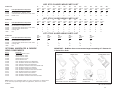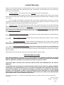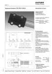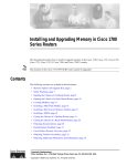
1
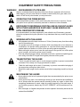
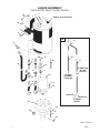
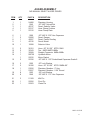
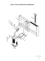
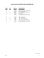
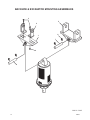
OPERATOR’S & PARTS
MANUAL
3K2 EARTH AUGER
SERIAL NUMBER: ___________________
MODEL NUMBER: ___________________
800-456-7100 I www.paladinlcg.com
Manual Number: 24523
Date: May 16, 2005
503 Gay Street, Delhi, IA 52223, United States of America
M-803
1-25-10-2
TO THE OWNER
GENERAL COMMENTS
Congratulations on the purchase of your new McMillen Earth Auger Attachment. Your earth
auger was carefully designed and manufactured to give you many years of dependable service. Your earth auger will require some minor maintenance (such as cleaning and lubricating) to keep it in top working condition. Be sure to observe all maintenance procedures and
safety precautions in this manual, on the safety decals located on the attachment, and on any
equipment on which the earth auger is mounted.
ABOUT THIS MANUAL
This manual has been designed to help you to do a better, safer job. Read this manual carefully, and become familiar with the operating procedures before attempting to operate your
earth auger. Remember, never let anyone operate this earth auger without them having read
and completely understand the “Safety Precaution” and “Operating Instructions” sections of
this manual, or having them be fully trained by an experienced, qualified person who has read
and completely understands the “Safety Precautions” and Operating Instructions”.
After reading this manual, if you have any questions about your attachment please contact us
immediately as follows:
NORTH AMERICAN TOLL FREE:
Outside North America:
Fax:
(800) 922-2981
(563) 922-2981
(563) 922-2700
SERVICE
When servicing this product, remember to use only manufacturer replacement parts. Substitute parts may not meet the standards required for safe, dependable operation.
To facilitate parts ordering, record the model and serial number of your unit in the space
provided on this page. This information may be obtained from the identification plate located
on the product.
MODEL: ____________________
SERIAL NO. ____________________
McMILLEN®
P.O. Box 266 • Delhi, Iowa 52223 • Phone (563) 922-2981 • Fax (563) 922-2700
North American Toll Free (800) 922-2981
24523
M-102 4-18-05-4
1
THIS PAGE
IS INTENTIONALLY
BLANK
2
24523
TABLE OF CONTENTS
Letter To The Owner ................................................................................................................... 1
Safety Statements ...................................................................................................................... 4
General Precautions ............................................................................................................... 4-6
Equipment Safety Precautions ................................................................................................... 7
Electric Select Auger Assembly Exploded View and Parts List ................................................ 8-9
Manual Select Auger Assembly Exploded View and Parts List ............................................ 10-11
Quick Attach Mounting Assemblies - Exploded View and Parts List ..................................... 12-13
Backhoe & Excavator Mounting Assemblies - Exploded View and Parts List ....................... 14-15
Universal Front End Loader Mounting Assembly #21235 - Exploded View and Parts List .... 16-17
Mounting & Installation Instructions ....................................................................................... 18-19
Hydraulic System Hook-up Instructions ..................................................................................... 20
Operating Instructions ............................................................................................................... 21
Maintenance Instructions ..................................................................................................... 22-24
Troubleshooting ........................................................................................................................ 25
Drive Unit Specifications .......................................................................................................... 26
Auger Parts List ....................................................................................................................... 27
Warranty................................................................................................................................... 28
M-805 5-9-05
24523
3
SAFETY STATEMENTS
THIS SYMBOL BY ITSELF OR WITH A WARNING WORD THROUGHOUT THIS
MANUAL IS USED TO CALL YOUR ATTENTION TO INSTRUCTIONS INVOLVING
YOUR PERSONAL SAFETY OR THE SAFETY OF OTHERS. FAILURE TO FOLLOW
THESE INSTRUCTIONS CAN RESULT IN INJURY OR DEATH.
DANGER
THIS SIGNAL WORD IS USED WHERE SERIOUS INJURY OR DEATH
WILL RESULT IF THE INSTRUCTIONS ARE NOT FOLLOWED PROPERLY.
WARNING
THIS SIGNAL WORD IS USED WHERE SERIOUS INJURY OR DEATH
COULD RESULT IF THE INSTRUCTIONS ARE NOT FOLLOWED PROPERLY.
CAUTION
THIS SIGNAL WORD IS USED WHERE MINOR INJURY COULD RESULT IF
THE INSTRUCTIONS ARE NOT FOLLOWED PROPERLY.
NOTICE
NOTICE INDICATES A PROPERTY DAMAGE MESSAGE.
GENERAL SAFETY PRECAUTIONS
WARNING!
READ MANUAL PRIOR TO INSTALLATION
Improper installation, operation, or maintenance of this equipment could result in
serious injury or death. Operators and maintenance personnel should read this
manual, as well as all manuals related to this equipment and the prime mover
thoroughly before beginning installation, operation, or maintenance. FOLLOW ALL
SAFETY INSTRUCTIONS IN THIS MANUAL AND THE PRIME MOVER’S
MANUAL(S).
READ AND UNDERSTAND ALL SAFETY STATEMENTS
Read all safety decals and safety statements in all manuals prior to operating or
working on this equipment. Know and obey all OSHA regulations, local laws, and
other professional guidelines for your operation. Know and follow good work practices
when assembling, maintaining, repairing, mounting, removing, or operating this
equipment.
KNOW YOUR EQUIPMENT
Know your equipment’s capabilities, dimensions, and operations before operating.
Visually inspect your equipment before you start, and never operate equipment that is
not in proper working order with all safety devices intact. Check all hardware to
ensure it is tight. Make certain that all locking pins, latches, and connection devices
are properly installed and secured. Remove and replace any damaged, fatigued, or
excessively worn parts. Make certain all safety decals are in place and are legible.
Keep decals clean, and replace them if they become worn or hard to read.
M-806
4
7-28-05-2
24523
GENERAL SAFETY PRECAUTIONS - CONTINUED
WARNING!
PROTECT AGAINST FLYING DEBRIS
Always wear proper safety glasses, goggles, or a face shield when driving pins in or
out, or when any operation causes dust, flying debris, or any other hazardous material.
WARNING!
LOWER OR SUPPORT RAISED EQUIPMENT
Do not work under raised booms without supporting them. Do not use support material made of concrete blocks, logs, buckets, barrels, or any other material that could
suddenly collapse or shift positions. Make sure support material is solid, not decayed,
warped, twisted, or tapered. Lower booms to ground level or on blocks. Lower booms
and attachments to the ground before leaving the cab or operator’s station.
WARNING!
USE CARE WITH HYDRAULIC FLUID PRESSURE
Hydraulic fluid under pressure can penetrate the skin and cause serious injury or
death. Hydraulic leaks under pressure may not be visible. Before connecting or
disconnecting hydraulic hoses, read your prime mover’s operator’s manual for
detailed instructions on connecting and disconnecting hydraulic hoses or fittings.
•
•
•
Keep unprotected body parts, such as face, eyes, and arms as far away as
possible from a suspected leak. Flesh injected with hydraulic fluid may develop
gangrene or other permanent disabilities.
If injured by injected fluid, see a doctor at once. If your doctor is not familiar with
this type of injury, ask him to research it immediately to determine proper treatment.
Wear safety glasses, protective clothing, and use a piece of cardboard or wood
when searching for hydraulic leaks. DO NOT USE YOUR HANDS! SEE ILLUSTRATION.
CARDBOARD
HYDRAULIC HOSE
OR FITTING
MAGNIFYING GLASS
M-807 7-28-05-2
24523
5
GENERAL SAFETY PRECAUTIONS - CONTINUED
WARNING!
DO NOT MODIFY MACHINE OR ATTACHMENTS
Modifications may weaken the integrity of the attachment and may impair the function,
safety, life, and performance of the attachment. When making repairs, use only the
manufacturer’s genuine parts, following authorized instructions. Other parts may be
substandard in fit and quality. Never modify any ROPS (Roll Over Protection Structure) or FOPS (Falling Object Protective Structure) equipment or device. Any modifications must be authorized in writing by the manufacturer.
WARNING!
SAFELY MAINTAIN AND REPAIR EQUIPMENT
•
•
•
•
•
Do not wear loose clothing or any accessories that can catch in moving parts. If
you have long hair, cover or secure it so that it does not become entangled in the
equipment.
Work on a level surface in a well-lit area.
Use properly grounded electrical outlets and tools.
Use the correct tools for the job at hand. Make sure they are in good condition for
the task required.
Wear the protective equipment specified by the tool manufacturer.
SAFELY OPERATE EQUIPMENT
Do not operate equipment until you are completely trained by a qualified operator in
how to use the controls, know its capabilities, dimensions, and all safety requirements. See your machine’s manual for these instructions.
• Keep all step plates, grab bars, pedals, and controls free of dirt, grease, debris,
and oil.
• Never allow anyone to be around the equipment when it is operating.
• Do not allow riders on the attachment or the prime mover.
• Do not operate the equipment from anywhere other than the correct operator’s
position.
• Never leave equipment unattended with the engine running, or with this attachment in a raised position.
• Do not alter or remove any safety feature from the prime mover or this attachment.
• Know your work site safety rules as well as traffic rules and flow. When in doubt
on any safety issue, contact your supervisor or safety coordinator for an explanation.
M-808 7-28-05-2
6
24523
EQUIPMENT SAFETY PRECAUTIONS
WARNING! KNOW WHERE UTILITIES ARE
Observe overhead electrical and other utility lines. Be sure equipment will clear them.
When digging, call your local utilities for location of buried utility lines, gas, water, and
sewer, as well as any other hazard you may encounter.
OPERATING THE PRIME MOVER
Avoid steep hillside operation, which could cause the prime mover to overturn. Consult
your prime mover operator’s and safety manuals for maximum incline allowable.
EXPOSURE TO RESPIRABLE CRYSTALLINE SILICA DUST ALONG
WITH OTHER HAZARDOUS DUSTS MAY CAUSE SERIOUS OR
FATAL RESPIRATORY DISEASE.
It is recommended to use dust suppression, dust collection and if necessary, personal
protective equipment during the operation of any attachment that may cause high levels
of dust.
WORKING WITH THE AUGER
• All bystanders should be kept a minimum of 10 feet (3 meters) away from the working
area of the earth auger.
• An operator must not use drugs or alcohol, which can change his or her alertness or
coordination. An operator taking prescription or over-the-counter drugs should seek
medical advice on whether or not he or she can safely operate equipment.
• Before exiting the prime mover, lower the earth auger to the ground, turn off the prime
mover’s engine, and lock the prime mover’s brakes.
• Flow and pressure gauges, fittings, and hoses must have a continuous operating pressure rating of at least 25% higher than highest pressures of the system.
TRANSPORTING THE AUGER
• Travel only with the earth auger in a safe transport position to prevent uncontrolled
movement. Drive slowly over rough ground and on slopes.
• Tether the earth auger with a chain, if necessary, to prevent uncontrolled swinging of
the auger when moving from hole to hole.
• Remove the earth auger from the prime mover before transporting to and from the job
site.
MAINTAINING THE AUGER
• Never adjust a relief valve for pressure higher than recommended by the prime mover
manufacturer.
• Never perform any work on an earth auger unless you are authorized and qualified to
do so. Always read the operator service manual(s) before any repair is made. After
completing maintenance or repair, check for correct functioning of the earth auger. If
not functioning properly, always tag “DO NOT OPERATE” until all problems are corrected.
• Worn, damaged, or illegible safety decals must be replaced. New safety decals can be
ordered from McMillen®.
M-809 9-17-07-2
24523
7
AUGER ASSEMBLY
3K2 ELECTRIC SELECT AUGER DRIVES
24
3
2
1
SERIAL TAG LOCATION
25
4
5
3
6
28
7
29
9
8
30
10
11
14
31
27
16
12
30 AMP FUSE
IN FUSE
HOLDER
17
TO WIRE
ASSEMBLY
ON AUGER
18
13
15
19
20
POSITIVE
NEGATIVE
TO PRIME
MOVER
21
22
24
23
26
10222 4-26-05
8
24523
AUGER ASSEMBLY
3K2 ELECTRIC SELECT AUGER DRIVES
ITEM
QTY
PART #
1
2
3
4
5
1
1
2
1
1
24522
1542
22680
24551
22315
Planetary Housing
.50” UNC Nylock Nut
Decal, Danger
Hose Clamp Cushion
Hose Clamp Plate
6
7
8
9
10
1
1
1
1
1
1096
40745
40557
3447
3313
.50” UNC X 3.00” Hex Capscrew
Decal, Model
Decal, Patent Pending
90° Elbow 10MJ-10FJX
90° Elbow 8MBo-10MJ
11
12
13
14
15
2
1
1
1
2
38201
30340
30053
38202
38200
Hose .50” X 7.00” 10MJ-10FJX
Tee 10MJ-10MJ-8MBoX
Tee 10MJ-10MJ-10MJ
Hose .50” X 24” 10FJX-10FJX 90°
Hose .50” X 7.88” 10FJX-10MBoX 90°
16
17
18
1
1
1
1
2
2
24479
30289
100756
22532
22336
1505
Directional Solenoid Valve
Straight Connector 8MBo-8MBo
Hydraulic Motor
Motor Gasket
.50” UNC X 1.50” SocketHead Capscrew Grade 8
.50” Lock Washer
22
23
24
25
1
1
8
8
3
1
23526
23527
1503
1046
21169
22256
Planetary Gearbox - 2” Hex
Planetary Gearbox - 2.56” Round
.38” Lock Washer
.38” UNC X 1.75” Hex Capscrew
Klik Pin
Pivot Pin
26
27
28
1
1
1
22263
101066
15757
29
30
1
1
17710
17712
Clevis Pin
Wire Assembly (Switch to Valve)
Control Box Assembly Option
(Includes Items 29 through 31)
Control Box Assembly
Wire Assembly (Switch to Valve)
31
1
17173
Wire Assembly (Switch to Battery)
19
20
21
DESCRIPTION
10223 4-26-05
24523
9
AUGER ASSEMBLY
3K2 MANUAL SELECT AUGER DRIVES
21
3
2
1
SERIAL TAG LOCATION
22
4
5
6
7
7
8
9
10
11
13
12
14
15
17
16
18
19
20
21
23
10218 3-15-05
10
24523
AUGER ASSEMBLY
3K2 MANUAL SELECT AUGER DRIVES
ITEM
QTY
PART #
1
2
3
4
5
1
1
1
1
1
24480
1542
40747
22317
22315
Planetary Housing
.50” UNC Nylock Nut
Decal, Selector Valve
Hose Clamp Cushion
Hose Clamp Plate
6
7
8
9
10
1
2
1
1
1
1096
22680
40557
40745
15088
.50” UNC X 3.00” Hex Capscrew
Decal, Danger
Decal, Patent Pending
Decal, Model
Selector Valve
11
12
13
14
2
2
1
1
1
2
38191
30343
30289
100756
22532
22336
Hose .50” X 6.50” 8FFS-10MJ
Tee 8MFS-8MFS-8MBo
Straight Connector 8MBo-8MBo
Hydraulic Motor
Motor Gasket
.50” UNC X 1.50” SocketHead Capscrew Grade 8
19
20
2
2
1
1
8
8
1505
38190
23526
23527
1503
1046
.50” Lock Washer
Hose .50” X 8.00” 8FFS-10MBo 90°
Planetary Gearbox - 2” Hex
Planetary Gearbox - 2.56” Round
.38” Lock Washer
.38” UNC X 1.75” Hex Capscrew
21
22
23
3
1
1
21169
22256
22263
Klik Pin
Pivot Pin
Clevis Pin
15
16
17
18
DESCRIPTION
10219 3-15-05
24523
11
QUICK ATTACH MOUNTING ASSEMBLIES
9
1
4
3
2
7
8
6
5
M-810 5-2-05
12
24523
QUICK ATTACH MOUNTING ASSEMBLIES
ITEM
QTY
PART #
DESCRIPTION
1
2
3
4
5
1
1
1
4
1
Varies
21694
22255
21169
22256
Quick Attach Mounting Bracket
Swivel Weldment
Pin, 1.25” Dia. x 7.25” Long
Lynch Pins
Pin (Included With Drive Unit)
6
7
8
9
9
1
4
4
1
1
21670
1228
1092
21690
21693
Mounting Cradle
.50” - 13 Hex Nut
.50” - 13 x 2” Gr. 5 Bolt
Spring Assembly (.50” Hose)
Spring Assembly (.75” Hose)
M-811 5-2-05
24523
13
BACKHOE & EXCAVATOR MOUNTING ASSEMBLIES
3
5
2
6
1
7
4
8
M-812 5-2-05
14
24523
BACKHOE & EXCAVATOR MOUNTING ASSEMBLIES
ITEM
QTY
PART #
DESCRIPTION
1
2
3
4
5
1
2
4
4
1
21626
Varies
1091
1841
Varies
Backhoe Base Weldment
Backhoe Adaptor Ear
.50” - 13 x 1.75” Gr. 5 Bolt
.50” - 13 Locknut
Fixed Backhoe Mount
6
7
8
2
1
1
21169
22255
22256
Lynch Pins
.1.25” Pin x 7.25” Long
Pin (Included With Drive Unit)
M-813 5-2-05
24523
15
UNIVERSAL FRONT END LOADER MOUNTING ASSEMBLY
ASSEMBLY #21235
5
4
7
2
1
6
8
3
5
M-814 5-2-05
16
24523
UNIVERSAL FRONT END LOADER MOUNTING ASSEMBLY
ASSEMBLY #21235
ITEM
QTY
PART #
DESCRIPTION
1
2
3
4
5
1
1
1
1
4
21628
21449
21694
22255
21169
Loader Bracket Weldment
Loader Bracket Pad (Included With Item #1)
Swivel Weldment
Pin, 1.25” x 7.25” Long
Lynch Pins
6
7
8
4
4
1
1080
1227
22256
.44 - 14 x 5.00”, Gr. 5 Bolt
.44 - 14 Hex Nut
Pin (Included With Drive Unit)
M-815 5-2-05
24523
17
MOUNTING & INSTALLATION INSTRUCTIONS
GENERAL INFORMATION
There are three types of mounting kits available for attaching your 3K2 2-speed earth drill:
1) Quick Attach Mounting Assemblies, 2) Backhoe & Excavator Mounting Assemblies, and
3) Universal Front End Loader Mounting Assembly. Find the mounting kit diagram and parts list for the
kit you have received. Study the diagram and familiarize yourself with the names of the various parts.
This knowledge will assist you in understanding these instructions.
Read these instructions carefully before attempting to mount the auger.
READ AND UNDERSTAND ALL SAFETY INFORMATION PRIOR TO MOUNTING YOUR AUGER.
QUICK ATTACH MOUNTING ASSEMBLIES
1.
Remove the bucket or other attachment from the vehicle quick attach mechanism.
2.
Attach the quick attach mounting bracket to vehicle quick attach mechanism, as per vehicle
manufacturer’s recommendations.
3.
Attach the swivel weldment (21694) to the quick attach mounting bracket with pin (22255).
Secure pin (22255) with lynch pins (21169).
4.
Attach and secure drive unit to swivel weldment (21694) with pin (22256) and lynch
pins (21169) provided with the drive unit assembly.
5.
Attach and secure auger to drive unit with bolt and nut provided with drive unit assembly.
6.
Refer to the “HYDRAULIC SYSTEM HOOK-UP” section in this manual for hydraulic connection
instructions and recommendations.
BACKHOE & EXCAVATOR MOUNTING ASSEMBLIES
1.
Remove bucket from dipper arm and curl cylinder pin connections. The dipper arm pin will be
used to attach backhoe mounting to backhoe dipper arm. Curl cylinder pin will not be required
for earth drill installation.
2.
If using a Universal (adjustable width) Backhoe Mounting, assemble by spacing the two adaptor
ears to the same width as the dipper arm, and secure to the backhoe swivel base (21626) with
four bolts (1091). Secure bolts (1091) and nuts (1841). After determining correct width,
backhoe adaptor ears must be welded to backhoe swivel base (21626).
3.
Attach backhoe mounting (universal or fixed) to the dipper arm using the dipper arm pin
removed from bucket in Step 1. Secure the bucket pin, as per vehicle manufacturer’s
recommendation.
M-832 5-2-05
18
24523
MOUNTING & INSTALLATION INSTRUCTIONS - CONTINUED
4.
Attach and secure drive unit to backhoe mounting with pin (21169) and pins (22256) provided
with the drive unit assembly.
5.
Attach and secure auger to drive unit, using bolt and nut provided with drive unit assembly.
6.
Refer to the ‘HYDRAULIC SYSTEM HOOK-UP’ section in this manual for hydraulic connection
instructions and recommendations.
UNIVERSAL FRONT END LOADER MOUNTING ASSEMBLY
1.
The Universal Front End Loader Mounting Assembly (#21235) can be used to adapt your
McMillen Hydraulic Earth Drill to the side of the loader arms, lip of bucket, or fork lift forks.
DO NOT USE ON SKID STEER LOADERS.
2.
Place loader bracket pad (21449) on the inside of the loader arm, top of bucket lip (for mounting
on lip of bucket you’ll need to drill two 7/16" diameter holes through bucket), or top of fork lift
fork. Opposite side of loader bracket pad (21449). Insert four bolts (1080), and secure with
four nuts (1227).
3.
Attach swivel weldment (21694) to the loader bracket weldment (21628) with pin (22255).
Secure pin (22255) with lynch pins (21169).
4.
Attach and secure drive unit to swivel weldment (21694) with pin and pin clips provided with the
drive unit assembly.
5.
Attach and secure auger to drive unit with bolt and nut provided with drive unit assembly.
6.
Refer to the ‘HYDRAULIC SYSTEM HOOK-UP’ section in this manual for hydraulic
connection instructions and recommendations.
M-833 5-2-05
24523
19
HYDRAULIC SYSTEM HOOK-UP INSTRUCTIONS
1. Once the installation instructions are complete, you are now ready to make the hydraulic connections
necessary to operate your earth drill. READ AND UNDERSTAND SAFETY INFORMATION PRIOR
TO MAKING HYDRAULIC CONNECTIONS.
2. Your equipment dealer is in the best position to advise you as to where the best place on your
machine is to make the hydraulic connections to power your earth drill drive unit. The list below
shows the most common places to “tap” into the hydraulic system on various types of machines.
• SKID STEER LOADERS - Auxiliary hydraulic outlets.
• BACKHOES & EXCAVATORS - Auxiliary hydraulic outlets or bucket curl cylinder circuit.
• WHEEL LOADERS & TRACTOR LOADERS - Auxiliary hydraulic outlets or bucket tilt (dump)
cylinder circuit.
• TRACTOR 3-POINT HITCHES - Remote (auxiliary hydraulic outlets).
• FORKLIFTS - Auxiliary hydraulic outlets or side-shift circuit.
3. Determine the length of hydraulic hoses required to plumb drive unit into the place on your machine
where you’ll be “tapping” into the hydraulics. Be sure the two hydraulic hoses are long enough to
perform at the full range of the earth drill’s operating capacity.
• Model 3K2 - This model requires two 1/2” (12.7mm) or 3/4” (19mm) ID hydraulic hoses, with #10
JIC Female fittings on one end of each hose, to connect hoses to drive unit fittings.
NOTE: Fittings on the other end of each hydraulic hose should match the threads on the hydraulic
quick couplers to be used.
WARNING!
HOSES AND FITTINGS MUST HAVE A CONTINUOUS OPERATING PRESSURE
RATING OF AT LEAST 25% HIGHER THAN THE HIGHEST PRESSURES OF THE
SYSTEM YOU ARE “TAPPING” INTO.
4. Once all of the hydraulic connections have been made and checked for leaks, you are now ready to
operate your earth drill. READ AND UNDERSTAND OPERATING INSTRUCTIONS AND SAFETY
INFORMATION PRIOR TO OPERATING YOUR EARTH DRILL.
M-824 4-26-05
20
24523
OPERATING INSTRUCTIONS
GENERAL INFORMATION
The 3K2 2-speed earth drill is available in two different configurations. One has a selector valve
for manually selecting either High Speed-Low Torque or Low Speed-High Torque, and the other has a
solenoid valve with an electric control box to select operating speed. The general digging is the same
as above except the operator has the option of selecting between the two different speeds. Generally in
light sandy soil or with the smaller diameter augers High Speed-Low Torque is the best operating
speed, whereas in hard ground conditions or digging with large diameter augers we recommend the
Low Speed-High Torque setting.
1. After all installation instructions have been completed, safety information read and understood, and
the rest of this operator’s manual has been reviewed, your McMillen Hydraulic Earth Drill is now
ready for use.
2.
Before beginning to dig, experiment with auger speed to determine which setting is best for your
ground condition and auger diameter.
3.
With the auger raised off the ground and the vehicle engine set at a low RPM, activate the earth
drill control valve to determine position control valve lever must be in to turn auger in a forward
(clockwise) rotation. This is the “digging” position.
4.
Return earth drill control valve to neutral position to stop the auger. Lower the auger to the ground
so that only the center point penetrates the ground about 2" (51mm).
5.
Activate the earth drill control valve so auger is turning in a forward (clockwise) rotation. Use only
enough down pressure to assure positive penetration of auger into the ground. Ease up on down
pressure if auger rotation slows down drastically or stalls. Excessive down pressure will cause the
auger to stall frequently.
6.
When auger has penetrated the ground about 24" (610mm), raise the auger from the hole to clean
the dirt out. Repeat this procedure until the desired hole depth is obtained.
7.
Once the required hole depth is reached, allow the auger to turn a few seconds at this depth to
clean the hole.
8.
Return the earth drill control valve to the neutral position to stop the rotation of the auger. Raise the
auger out of the hole, move away from the hole, then activate the earth drill control valve to spin the
loose soil off of the augers.
NOTE: Do not reverse the auger rotation to remove from the hole, as loose soil on the auger flights will
fall back into the hole.
9.
If necessary, repeat steps 7 & 8 to obtain a cleaner hole.
10. In some soil conditions or when excessive down pressure is applied, auger may “screw” itself into
the ground and become stuck, causing the earth drill to stall. If this happens, reverse the auger
rotation (counter-clockwise) by moving the control valve lever to the reverse position, and slowly
raise the auger. Once unstuck, return the control valve lever to the forward rotation position, and
continue digging.
11. If the auger becomes lodged under rocks, roots, or other large obstructions, do not attempt to raise
the auger out of the ground. See step 10 for the proper procedure to relieve the auger.
12. Avoid excessive side loading to earth drill, which can cause drive unit or auger damage.
13. Keep auger teeth and points in good condition. Check frequently, and always keep spares on hand
so they can be replaced as wear is detected, to avoid damage to tooth holders and auger flighting.
10224 3-17-05
24523
21
MAINTENANCE INSTRUCTIONS
1. CLEAN HYDRAULIC OIL IS ESSENTIAL! 80% of all hydraulic component failures are caused by
contamination of the hydraulic oil. Always keep all dirt and other contaminates from entering the
hydraulic system during disconnect and connect operations. Always use dust caps and plugs on all
quick disconnects when not in use. Tightly cap all hydraulic openings to hold oil in and keep dirt and
other contaminates from entering hydraulic systems.
2. CHECK HYDRAULIC OIL DAILY FOR CONTAMINATION. If contamination is present, determine
the source of the problem.
3. INSPECT ALL HYDRAULIC HOSE ASSEMBLIES DAILY for cracked and brittle covers caused by
excessive heat. Reduced viscosity of hydraulic oil occurs at higher operating temperatures and
causes a breakdown of fluid additives, such as wear inhibitors. Excessive heat will cause higher
internal leakage in the drive unit motor, which will make the drive unit less efficient. It can also cause
seals in the drive unit motor to become brittle and crack. Replacement of hoses before failure will
prevent loss of hydraulic oil, time consuming “bleeding” of the system, hydraulic oil contamination,
and component damage caused by cavitation. It will also reduce the chance of personal injury
caused by hydraulic fluid.
4. CHECK AUGER DAILY for loose, worn, or broken cutting teeth and point. Worn teeth or point can
drastically affect auger penetration, and greatly reduce auger life expectancy. Always keep spare
teeth and points on hand. Some digging conditions may require checking teeth and point at more
frequent intervals.
5. CHECK DRIVE UNIT AND ALL ACCESSORIES DAILY for loose, bent, cracked, or worn bolts and
fasteners. Always use Grade 5 or harder replacements bolts. Always use lock washers with
standard hex nuts or self locking nuts.
6. CHECK ALL CONNECTING PINS DAILY for bends, cracks, breaks, or wear. Replace if any of
these conditions exist.
7. CHECK DRIVE UNIT OUTPUT SHAFT DAILY for bends, cracks, breaks, or wear. Replace if any of
these conditions exist.
8. CHANGE PLANETARY GEAR REDUCTION OIL AFTER FIRST 50 HOURS OF OPERATION,
THEN EVERY 1000 HOURS OR TWELVE MONTHS, WHICHEVER COMES FIRST. Use mild
extreme pressure lubricant API-GL-5, no. 80 or 90 for filling the planetary gear reduction under
normal temperature ranges between 0° -120° F (-18° - 49° C). The approximate oil capacity for
model 3K2 is two pints (.95 liters). CHECK OIL LEVEL DAILY to assure proper lubrication is maintained.
9. WHEN STORING DRIVE UNIT for any length of time, be sure the drive unit motor and hoses are
full of clean oil. Be sure the planetary gear reduction is full (to the recommended capacity for each
model), as outlined in number 8 above.
M-825 4-26-05
22
24523
MAINTENANCE INSTRUCTIONS
10. The Drive Unit output shaft, inside of auger collar, variable auger extension shaft, inside of variable
auger extension collar, and all connecting pins should be coated liberally with grease, to prevent rust
and reduce wear.
11. Once paint has been worn off the auger, coat liberally with grease, as required, to prevent rusting.
12. Check planetary gear oil as follows: Lay drive unit horizontal with the ground and with drain plug
straight up. Verify that the output shaft is completely covered with oil. Add as needed.
M-826 4-26-05
24523
23
MAINTENANCE INSTRUCTIONS
PLANETARY GEAR REDUCTION FOR 3K2
Exploded View and Parts List
* WARRANTY NOTICE: Any attempt to disassemble or make field repairs to the planetary will
void warranty. Contact your Dealer/Distributor.
1
2
3
4
6
5
8
3
9
10
11
7
12
9
13
14
15
17
16
18
ITEM #
1
1
2
3
4
5
6
7
8
9
10
QTY
1
1
1
2
1
1
1
8
1
2
1
PART #
15071
15072
33510
31681
101526
15073
15074
31671
15075
31674
31675
11
12
13
14
15
16
17
18
19
1
1
1
1
1
8
1
2
2
15335
15336
31673
31672
31670
31685
15076
15077
31664
24
19
DESCRIPTION
2-9-16” Round Shaft
2” Hex
Seal
Bearing/Cone
Lock Nut with Tab Washer (Replaces Nut with Key)
Spacer
Plug
Bolt
Housing
O-Ring
Ring Gear
Gear Set
Sun Gear
Thrust Washer
Cover
Gasket
Nut
Plate
Washer
Bolt
M-827 4-26-05
24523
TROUBLESHOOTING
PROBLEM
POSSIBLE CAUSE
SOLUTION
Slow Speed
Low Flow
Check with flow meter. If low
investigate cause.
Line restrictions
Clear lines.
Fittings or connections too small
Replace with proper sizes.
Oil filter dirty
Replace.
Hydraulic pump worn or damaged
See Dealer for repair.
Worn teeth or point
Replace.
Low system Pressure (PSI)
Check with pressure gauge. If low,
investigate cause.
Relief Valve damaged or setting wrong
Adjust or replace as required.
Excessive load
Reduce load to within machine
specifications.
Solenoid valve damaged.
Check and replace, as required.
Selector valve damaged.
Check and replace, as required.
Reverse Direction
Hoses reversed
Re-install hoses correctly.
Excessive Oil Heating
Line restrictions
Clear lines.
Fluid dirty
Replace hydraulic fluid and filter.
Insufficient quantity of hydraulic fluid
Fill reservoir to proper level.
Increase reservoir storage capacity.
Hoses loose or damaged
Tighten or replace.
Fittings loose or damaged
Tighten or replace.
Insufficient Digging Power
Won’t Shift Between High
& Low Gear
Oil Leaks
Hydraulic motor seals worn or damaged See Dealer for repair.
M-831 4-27-05
24523
25
DRIVE UNIT SPECIFICATIONS
MODEL 3K2
Maximum Auger Diameter:
Minimum Hydraulic Flow:
Maximum Hydraulic Flow:
Maximum Continuous Operating PSI:
Output Shaft Options:
OUTPUT SPEED
FLOW
GPM (LPM) =
15
(57) =
20
(76) =
LOW
SPEED
RPM
37
48
HIGH
SPEED
RPM
59
81
36” (914 mm)
10 gpm (38 lpm)
25 gpm (95 lpm)
3000 psi (207 bar)
2-9/16” (65mm) Round
2” (51mm) Hex
OUTPUT TORQUE
HIGH
LOW
PRESSURE
TORQUE
TORQUE
PSI (BAR) = Lb•Ft(N•m) Lb•Ft(N•m)
3000(207) = 2053(2783) 2923(3963)
M-830 4-26-05
26
24523
HDC STYLE AUGER WEAR PARTS LIST
AUGER DIA.
Part #
22169
22168
22190
22154
Description(Standard Components)
Hardened Drive-In Gage Tooth
Hardened Drive-In Wisdom Tooth
3.50” Hardened Fishtail Point (male shaft)
Rubber Lock
6"
8"
9"
10"
12"
15"
16"
18"
20"
24"
30"
36"
42"
152mm
203mm
229mm
254mm
305mm
381mm
406mm
457mm
508mm
610mm
762mm
914mm
1067mm 1219mm
48"
Qty
2
1
2
Qty
2
2
1
4
Qty
2
2
1
4
Qty
2
2
1
4
Qty
2
2
1
4
Qty
2
4
1
6
Qty
2
4
1
6
Qty
2
4
1
6
Qty
2
4
1
6
Qty
2
6
1
8
Qty
2
8
1
10
Qty
2
10
1
12
Qty
2
14
1
16
4"
6"
36"
Qty
2
18
1
20
HDF STYLE AUGER WEAR PARTS LIST
AUGER DIA.
Part #
22169
22168
22190
22003
22306
1839
Description(Standard Components)
Hardened Bolt-on Gage Tooth
Hardened Bolt-on Wisdom Tooth
3.50” Hardened Fishtail Point (male shaft)
4.50” Hardened Fishtail Point
Carriage Bolt
Nut
AUGER DIA.
Part #
22169
22168
22190
22306
1839
Description(Standard Components)
Hardened Bolt-on Gage Tooth
Hardened Bolt-on Wisdom Tooth
3.50” Hardened Fishtail Point (male shaft)
Carriage Bolt
Nut
8"
9"
10"
12"
15"
16"
18"
20"
24"
30"
102mm
152mm
203mm
229mm
254mm
305mm
381mm
406mm
457mm
508mm
610mm
762mm
914mm
Qty
1
-
Qty
2
1
2
2
Qty
2
1
2
2
Qty
2
1
1
3
3
Qty
2
1
1
3
3
Qty
2
2
1
4
4
Qty
2
3
1
5
5
Qty
2
3
1
5
5
Qty
2
4
1
6
6
Qty
2
4
1
6
6
Qty
2
6
1
8
8
Qty
2
7
1
9
9
Qty
2
9
1
11
11
HTF STYLE AUGER WEAR PARTS LIST
18"
24"
30"
36"
42"
457mm
610mm
762mm
914mm
1067mm
1219mm
QTY
4
3
1
7
7
QTY
4
6
1
10
10
QTY
4
7
1
11
11
QTY
4
9
1
13
13
QTY
4
11
1
15
15
QTY
4
13
1
17
17
OPTIONAL HARDFACED & CARBIDE
WEAR COMPONENTS
Part #
22170
22186
22181
22183
22182
22190
22192
22191
22193
22003
22004
22005
22171
22172
22173
22174
Description
Hardfaced Wisdom Tooth
Carbide Wisdom Tooth
Hardened Chisel Tooth
Hardfaced Chisel Tooth
Carbide Chisel Tooth
3.50” Hardened Fishtail Point (Male Hub)
3.50” Hardfaced Fishtail Point (Male Hub)
3.50” Carbide Fishtail Point (Male Hub)
3.50” Hardfaced /Carbide Fishtail Point (Male Hub)
4.50” Hardened Fishtail Point (Female)
4.50” Hardfaced Fishtail Point (Female)
4.50” Hardfaced /Carbide Fishtail Point (Female)
3.50” Hardened Fishtail Point (Female)
3.50” Carbide Fishtail Point (Female)
3.50” Hardfaced Fishtail Point (Female)
3.50” Hardfaced /Carbide Fishtail Point (Female)
NOTE: Contact your equipment dealer for wear components not listed above.
If you have any special auger needs or applications, feel free to contact
McMillen.
24523
48"
IMPORTANT: McMillen does not recommend augers exceeding 36” diameter for
C-Series Drive Units.
Gage Tooth
Wisdom Tooth
Fishtail Point
Fishtail Point
With Female Connector With Male Hub
Chisel Tooth
Weld-on Drive Lug
For Male Hub
Carbide Wisdom Tooth
Weld-on Drive Lug
For Female Connector
M-118 4-27-05-3
27
Limited Warranty
Except for the Excluded Products as described below, all new products are warranted to be free from defects in
material and/or workmanship during the Warranty Period, in accordance with and subject to the terms and conditions of this Limited Warranty.
1.
Excluded Products. The following products are excluded from this Limited Warranty:
(a) Any cable, part that engages with the ground (i.e. sprockets), digging chain, bearing, teeth, tamping
and/or demolition head, blade cutting edge, pilot bit, auger teeth and broom brush that either constitutes or is part
of a product.
(b) Any product, merchandise or component that, in the opinion of Paladin Light Construction1, has been
(i) misused; (ii) modified in any unauthorized manner; (iii) altered; (iv) damaged; (v) involved in an accident; or (vi)
repaired using parts not obtained through Paladin Light Construction.
2.
Warranty Period. The Limited Warranty is provided only to those defects that occur during the Warranty
Period, which is the period that begins on the first to occur of: (i) the date of initial purchase by an end-user, (ii) the
date the product is first leased or rented, or (iii) the date that is six (6) months after the date of shipment by Paladin
Light Construction as evidenced by the invoiced shipment date (the “Commencement Date”) and ends on the date
that is twenty-four (24) months after the Commencement Date. (NOTE: The Planetary Gearbox ONLY carries
an additional 3 years warranty.)
3.
Terms and Conditions of Limited Warranty. The following terms and conditions apply to the Limited Warranty
hereby provided:
(a)
the product.
Option to Repair or Replace. Paladin Light Construction shall have the option to repair or replace
(b)
Timely Repair and Notice. In order to obtain the Limited Warranty, (i) the product must be repaired
within thirty (30) days from the date of failure, and (ii) a claim under the warranty must be submitted to Paladin Light
Construction in writing within thirty (30) days from the date of repair.
(c)
Return of Defective Part or Product. If requested by Paladin Light Construction, the alleged defective
part or product shall be shipped to Paladin Light Construction at its manufacturing facility or other location specified
by Paladin Light Construction, with freight PRE-PAID by the claimant, to allow Paladin Light Construction to inspect
the part or product.
Claims that fail to comply with any of the above terms and conditions shall be denied.
LIMITATIONS AND EXCLUSIONS.
THIS LIMITED WARRANTY IS IN LIEU OF ALL OTHER WARRANTIES, EXPRESS OR IMPLIED, INCLUDING
WITHOUT LIMITATION THE WARRANTIES OF MERCHANTABILITY, FITNESS FOR A PARTICULAR PURPOSE
AND ANY WARRANTY BASED ON A COURSE OF DEALING OR USAGE OF TRADE.
IN NO EVENT SHALL PALADIN LIGHT CONSTRUCTION BE LIABLE FOR CONSEQUENTIAL OR SPECIAL
DAMAGES.
IN NO EVENT SHALL PALADIN LIGHT CONSTRUCTION BE LIABLE FOR ANY LOSS OR CLAIM IN AN AMOUNT
IN EXCESS OF THE PURCHASE PRICE, OR, AT THE OPTION OF PALADIN LIGHT CONSTRUCTION, THE REPAIR OR REPLACEMENT, OF THE PARTICULAR PRODUCT ON WHICH ANY CLAIM OF LOSS OR DAMAGE
IS BASED. THIS LIMITATION OF LIABILITY APPLIES IRRESPECTIVE OF WHETHER THE CLAIM IS BASED
ON BREACH OF CONTRACT, BREACH OF WARRANTY, NEGLIGENCE OR OTHER CAUSE AND WHETHER
THE ALLEGED DEFECT IS DISCOVERABLE OR LATENT.
Attachment Technologies Inc., a subsidiary of Paladin Brands Holding, Inc. (PBHI) is referred to herein as Paladin Light
Construction.
February 10, 2010
1
M-804
28
2-15-10-3
24523