1
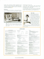
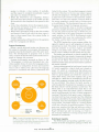
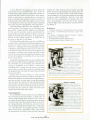
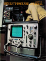
»- V Ei ^ Fig. 1. Model 1740 A Oscillo scope can display the sweep trig ger waveform as a third trace simultaneously with the wave forms in channels A and B. The new oscilloscope has dc-to100-MHz bandwidth, selectable input impedance (high impe dance or a well-matched 50Ãœ), precision delayed sweep, a bright, finely-focussed trace, and all the other characteristics of a high-quality laboratory oscilloscope. to be compared to the signals in both vertical chan nels. Of particular interest to digital designers is an option that enables the new scope to serve as the digital display for a logic state analyzer, with instant pushbutton restoration of the analog display when ever desired (Fig. 2). x5 Vertical Magnifier In earlier high-frequency oscilloscopes, increased sensitivity at reduced bandwidth in the vertical chan nel was obtained by cascading the two vertical chan nels into one channel, thus sacrificing the dualchannel display. In the new Model 1740A Oscil loscope, the X5 magnifier operates on both vertical channels, increasing the sensitivity from a vertical deflection factor of 5mV/cm to 1 mV/cm, at a band width of 40 MHz, while retaining dual-channel oper ation. In this mode the two channels may display sig nals separately in either the alternate or chopped dis play mode, or they may be combined (A — B) for singlechannel display of differential signals. Trigger Display When two signals are being displayed on the Model 1740A in either the alternate or chopped modes, pressing the TRIG VIEW pushbutton adds a third trace, giving a three-channel display (Fig. 2b). The third trace displays the sweep trigger signal, thus enabling the user to make timing measurements between an external trigger signal and the signals in channels A and B. The propagation delay through the triggerview channel matches those of the vertical channels within 2.5 ns ± 1 ns, thus assuring integrity in timing comparisons between the external trigger signal and the signals in channels A and B. In effect, the trigger-view mode provides a third, 80-MHz channel for viewing a signal applied at the trigger input. The deflection factor is nominally 100 mV/div, compatible with ECL logic levels, or 1 V/div with the xio attenuator, compatible with TTL and CMOS levels. These are changed to 20 mV/div and 200 mV/div when the x 5 magnifier is used. When the sweep is triggered by the signal in chan nel A or B, the trigger-view channel displays the same signal with approximately the same deflection factor and, as with an external trigger, it may be posi tioned by the TRIGGER LEVEL control to show the trig gering point. The dc levels of the trigger amplifier are set so the sweep trigger level corresponds to the center horizontal graticule line on the CRT, thus the operator can see which point on the waveform ini tiates the sweep. The displayed waveform is also processed through the trigger input filtering (HF REJECT, LF REJECT) so the operator sees the waveform exactly as the triggerrecognition circuit sees it. The trigger-level control functions like a positioning control, displacing the waveform vertically so the operator can choose a trig ger level that avoids the likelihood of triggering on noise or other waveform anomalies © Copr. 1949-1998 Hewlett-Packard Co.