1
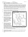
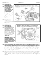
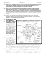
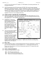
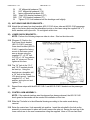
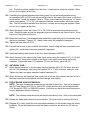
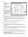
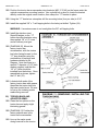
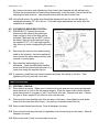
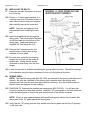
FORM #3145.03-110209 PRINTED IN U.S.A. PAGE 15 OF 23 NOTE: Using a line wrench is recommended for all brake line connections. Unclip the brake line from the bracket securing it to the side of the frame and unbolt the bracket from the frame. Attach a brake line bracket (#55-28-3120) to the frame in the same location as the factory bracket that was just removed and as shown in Diagram 9. Use the factory hardware and tighten (10). Install the appropriate female / female adapter fitting (#47-3120 or #48-3120) on one end of each brake line extension (#45-3120 or #46-3120). Tighten using a line wrench. Connect the female end of the “45” or “46” brake line extension to the metal brake line at the frame. Verify that the rubber brake hose is still routed under the upper control arm, then connect the male end of the extension to the rubber brake hose and tighten both connections. Secure the factory brake line support bracket to the “28” bracket as shown in Diagram 9 using the supplied 1/4” x 1-1/4” bolts, washers, and nyloc nuts (9). Tighten the caliper assembly to factory specifications. Unclip the ABS connector located at the top of the frame. Mark and drill a 1/4” hole approximately mid-way down the side of the frame directly below where the connector was originally located. Reroute the connector to the side of the frame and secure it in the hole drilled in the previous step. If needed, additional slack can be gained by unwrapping a section of the ABS wires from the rest of the wire loom in the engine compartment. Route the ABS wire as shown in Diagram 9, then reattach it to the connector. Secure both the factory brake hose and ABS wire guide brackets to the front leg of the upper control arm and secure using the supplied 1/4” x 1-1/4” bolt, washer, and nyloc nut (9). 24) TORSION BAR DROP BRACKETS… NOTE: If the vehicle is equipped with the ZR5 appearance package you must remove the step bar brackets located on the frame rail outside the torsion bar mounting location.