1
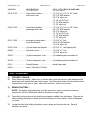
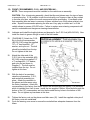
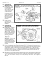
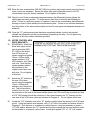
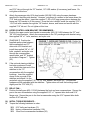
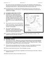
FORM #3145.03-110209 PRINTED IN U.S.A. PAGE 21 OF 23 37) TURNING RADIUS STOPS… NOTE: Some deeply inset wheels, when turned full lock, may make slight contact with the upper control arm. Even if the wheels are not making contact, the close clearance may interfere with wheel balancing weights. If either problem exists, perform this step. In some cases it may be necessary to abandon knock-on weights in favor of tape-ons. Locate the factory turning radius stops on the rear of the lower control arms and prep the area for welding. [DIAGRAM 15] Weld the furnished 3/8" O.D. x 1" long piece of half-section tubing onto both factory turning radius stops as shown. After the area has cooled, paint the exposed surfaces. 38) ADJUSTING FRONT RIDE HEIGHT... Manually bounce the front and rear of vehicle to normalize the torsion bars and leaf springs. [DIAGRAM 15] Position the vehicle on a level surface. Measure from the LCA front pivot bolt center down to the floor. Record this as Measurement “A”. Now measure from the inside edge of the knuckle (at the lower ball joint boss) down to the floor. Record this as Measurement “B”. Subtract measurement “B” from “A” for the ride height figure. Minimum ride height is 4.6”; maximum is 5.2”. Preferred ride height is 4.9”. Raise height by tightening the torsion bar adjusting bolt; lower height by loosening the bolt. Adjust height 3/8” to 1/2” above the final desired ride height, since the bars will settle slightly after the vehicle is driven. NOTE: Exceeding the stated minimum or maximum heights will cause the suspension to continually “top out” or “bottom out”. This results in a harsh ride, accelerated suspension component wear, and possibly component failure.