1
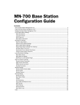
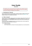
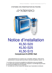
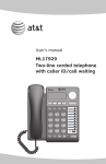
Home Network Connection Center Installation Manual Third Edition March 1999 The following paragraph does not apply to any state or country where such provisions are inconsistent with local law: INTERNATIONAL BUSINESS MACHINES CORPORATION PROVIDES THIS PUBLICATION AS IS WITHOUT WARRANTY OF ANY KIND, EITHER EXPRESS OR IMPLIED, INCLUDING, BUT NOT LIMITED TO, THE IMPLIED WARRANTIES OF MERCHANTABILITY OR FITNESS FOR A PARTICULAR PURPOSE. References to IBM products, programs, or services do not imply that IBM intends to make them available outside the United States. This publication could contain technical inaccuracies or typographical errors. Changes are periodically made to the information herein; these changes will be made in later editions. IBM may make improvements and/or changes in the product(s) and/or program(s) at any time. Address comments about this publication to Product Support Manager IBM Home Director, IBM Corporation, 3039 Cornwallis Rd., Dept. XJQA, Research Triangle Park, NC 27709-2195 USA. Information you supply may be used by IBM without obligation. For copies of publications related to this product, call toll free 1-800-IBM-7282 in the Continental U.S.A. In Canada, call toll free 1-800-465-7999. © Copyright International Business Machines Corporation 1999. All rights reserved. Note to U.S. Government Users Documentation related to restricted rights Use, duplication or disclosure is subject to restrictions set forth in GSA ADP Schedule Contract with IBM Corp. Notices iv Notices Notices References in this publication to IBM products, programs, or services do not imply that IBM intends to make these available in all countries in which IBM operates. Any reference to an IBM product, program, or service is not intended to state or imply that only IBMs product, program, or service may be used. Any functionally equivalent product, program, or service that does not infringe any of IBMs intellectual property rights may be used instead of the IBM product, program, or service. Evaluation and verification of operation in conjunction with other products, except those expressly designated by IBM, are the users responsibility. Danger! To avoid a shock hazard: Do not connect or disconnect any cables or perform installation, maintenance, or reconfiguration of this product during an electrical storm. The power cord must be connected to a properly wired and earthed receptacle. Any equipment to which this product will be attached must also be connected to properly wired receptacles. Pour éviter une décharge électrique: Ne branchez ni ne débranchez de câbles et neffectuez pas dinstallation, de maintenance ni de reconfiguration pendant un orage. Le cordon dalimentation doit être branché sur une prise de courant correctement câblée et mise à la terre. IBM may have patents or pending patent applications covering subject matter in this document. The furnishing of this document does not give you any license to these patents. You can send license inquiries, in writing, to the IBM Director of Licensing, IBM Corporation, 500 Columbus Avenue, Thornwood, NY 10594. Installation The HomeNetwork Controller and HomeNetwork Connection Center are intended for installation only by IBM authorized installers. Safety Information To avoid a shock hazard: Do not connect or disconnect any cables or perform installation, maintenance, or reconfiguration of this product during an electrical storm. The power cord must be connected to a properly wired and earthed receptacle. Any equipment to which this product will be attached must also be connected to properly wired receptacles. For further details concerning option installation, configuration or repair, please refer to IBM document #SD21-0030-04. General Information Electrostatic Sensitive Devices. Some components in the Home Director system are sensitive to electrostatic discharge. Use an electrostatic discharge (ESD) strap to establish a personal ground. If you do not have an ESD strap, establish a personal ground by touching a ground point before handling a static-sensitive part. Tout équipement auquel cette unité sera connectée devra également être branché sur des prises correctement câblées. v Important Notice. All components of the Home Director system have been tested and found to comply with the limits for a Class B digital device, pursuant to Part 15 of the FCC Rules. These limits are designed to provide reasonable protection against harmful interference in a residential installation. The equipment generates, uses, and can radiate radio frequency energy and, if not installed and used in accordance with the instructions, may cause interference to radio communications. However, there is no guarantee that interference will not occur in a particular installation. If this equipment does cause harmful interference to radio or television reception, which can be determined by turning the equipment off and on, the user is encouraged to try to correct the interference by one or more of the following measures: Reorient or relocate the receiving antenna. Increase the separation between the equipment and receiver. Connect the equipment into an outlet on a circuit different from that to which the receiver is connected. Consult an IBM Authorized Home Systems Integrator for help. Properly shielded and grounded cables and connectors must be used in order to meet FCC emission limits. Proper cables and connectors are available from IBM Authorized Home Systems Integrators. IBM is not responsible for any radio or television interference caused by using other than recommended cables and connectors or by unauthorized changes or modifications to this equipment. Unauthorized changes or modifications could void the users authority to operate the equipment. All components in the Home Director system have been tested and found to comply with the limits for a Class B CSTD device pursuant to Part 15 of FCC Rules. Operation is subject to the following two conditions: (1) this device may not cause harmful interference, and (2) this device must accept any interference received, including interference that may cause undesired operation. Responsible Party. International Business Machines Corporation New Orchard Road Armonk, NY 10504 Telephone: 1-919-543-2193 This Class B digital apparatus complies with Canadian ICES-003. Cet appareil numérique de la classe B est conform à la norme NMB-003 du Canada. Agency Notices Underwriters Laboratories (UL) requires that a minimum of 1/4 space be maintained at all times between Class 2 DC power cables. All Class 2 DC power cables in this installation must conform to this requirement. Trademarks The following terms are trademarks or registered trademarks of the IBM Corporation in the United States or other countries or both: vi Notices IBM Home Director Other company, product, and service names may be trademarks or service marks of others. Microsoft, Windows, and the Windows 95 logo are trademarks or registered trademarks of Microsoft Corporation. vii Conventions used in this book Highlighting There are several ways that text is highlighted in this book. Each highlighting convention has a specific purpose. Highlight viii Purpose Bold Bold font is used to identify items on the screen which you should click or double-click. Bold font is also used in headings, table titles, and numbered lists. Example Example font is used to show text that you need to type from your keyboard. Italic Italic font is used to show proper names of programs or books. Italic font is also used in table footnotes and sidenotes. Quotes Quotation marks are used to identify window, screen, and heading names. Underline Underline font is used to call special emphasis to a particular word or instruction. Conventions used in this book Chapter 1: Table of Contents v Notices v Installation v Safety Information v General Information vi Agency Notices vi Trademarks viii Conventions used in this book viii Highlighting 3 General Installation Information 3 Major system component descriptions 3 Home Network Connection Center location 5 Measurements 5 Tools required 6 Framing space in an interior wall for the Home Network Connection Center 6 Framing requirements 7 Installing the Home Network Connection Center cabinet (rough-in) 7 Parts list 7 Installing the cabinet in the wall 7 Drywall 8 Pre-wiring requirements and best practices 8 Power requirements 8 Low voltage wiring information 11 Installing the top trim and side panels 11 Parts list 11 Installing trim panels 13 Installing Home Network Connection Center components 13 Parts List 13 Connecting power and ground cables 15 Installing the 6 Way (Video) Amplifier / 8 Way Phone Module 16 Installing the Web Point Internet Distribution Center 17 Installing the Computer Networking (Ethernet) Module 19 Installing the Residential Telcom Module 19 Installing the Camera Module 20 Installing the Power Distribution Module 20 Installing blank panels ix x 20 Installing the Video Distribution Amplifier 22 Connecting cables 22 Connecting the internal power cables for the 2xxx or 3xxx 23 Connecting cables for the 1xxx Package 24 Connecting cables for 2xxx and 3xxx Packages 28 Installing wall plate (tap point) connections 28 Verifying connections in the Home Network Connection Center 31 Installing the Home Network Connection Center front panel 31 Parts list 31 Installing the 1xxx Package Front Panel 32 Installing the 2xxx or 3xxx Package Front Panel 33 Final Steps Installation 2 Installation General Installation Information This document contains information for the installation of several models of the IBM Home Network Connection Center. If the model you are installing does not include components discussed in this document, the information will not apply. In some cases, additional components are available as upgrades. All packages are listed as 1xxx, 2xxx, or 3xxx. Follow the instructions for the package and options you are installing. Major system component descriptions This section is provided for your reference. It contains a brief description of major system components that may be included with the Home Network Connection Center. Home Network Connection Center cabinet. Cabinet housing a combination of modules which receive and distribute signals throughout the home. The cabinet may come with any of the following modules: 6 Way Amplifier / 8 Way Phone Module. Connection center for voice and video communication lines in the Home Network Connection Center 1xxx Package. Residential Telcom Module. Connection center for voice and data communication lines. Video Distribution Amplifier. There are several types of distribution modules. The module you are installing allows connection and, in some cases, amplification of some or all of the following signals: Cable, DBS, UHF, VHF, and other coaxial signals. Computer Networking Module. Connection center for homeowner supplied computers with properly configured Ethernet network cards and software. Camera Module. Connection center for closed circuit monitoring television cameras (cameras and power supplies are sold separately). Power Distribution Module. Connection center for internal DC power cables to other modules. Danger! In all cases, refer to the National Electrical Code (N.E.C.), Canadian Electrical Code (if appropriate), and other local building codes for acceptable practices. Dans tous les cas, consultez le Code national de lélectricité, le Code canadien de lélectricité et les autres codes locaux de la construction. Web Point Internet Distribution Center. Connection center for Internet access and additional homeowner supplied computers with properly configured Ethernet network cards and software. Home Network Connection Center location The location must be a clean interior space, no less than 6 from a Load Center (or Breaker Box) temperature controlled and secure. Install the components only in a dry (non-condensing) location as described in the National Electrical Code (N.E.C.) or the Canadian Electrical Code. The following are acceptable locations: A dedicated wiring closet (ideal installation). A storage closet (if appropriate space is available). A basement or utility room which is considered dry as described in the N.E.C. General Installation Information 3 DO NOT install the components in a garage, crawl space, or exterior enclosure. (NINSTALLEZ PAS les composantes dans un garage, une galerie technique ou une enveloppe de bâtiment.) DO NOT install in a fire rated wall. These are not IBM approved installation locations. (NINSTALLEZ PAS dans un mur coupe-feu. Ce type dinstallation nest pas approuvé par IBM.) The Home Network Connection Center should be installed no more than 20 feet and no less than 3 inches from the desired future location of a Home Network Controller. Operating Environment. Ambient Temperature Operating 16 ºC to 32 ºC (60.8 ºF to 89.6 ºF) Non-operating 10 ºC to 43 ºC (50 ºF to 109.4 ºF) Humidity 4 Operating 8% to 80%, no condensation Non-operating 8% to 80%, no condensation General Installation Information Installation Measurements The basic installation has the following general components and preferred measurements. Note When installed, the Home Network Connection Center cabinet must protrude 1-1/4 from the finished face of the drywall. There must also be 1/4 of open space behind the cabinet. Tools required The following list contains most of the tools you will need during the installation. Tools are not listed in the order they are needed. Screwdrivers (#2 Phillips, small flat head, large flat head) Strip and crimp tool for RG-6 cables male F connectors Strip and crimp tool for UTP 8 position 8 conductor jacks General Installation Information 5 Framing space in an interior wall for the Home Network Connection Center The Home Network Connection Center must be located according to the information in General Installation Information on page 3. Framing requirements The outside dimension of the cabinet is 19-1/2H x 14-1/4W x 4-1/2D. Note DO NOT mount the cabinet in a fire rated wall. NINSTALLEZ PAS les composantes dans un mur coupe-feu. 6 The cabinet must be lagged into the side studs with required mounting hardware on both sides (normal studs on 16 centers). No top or bottom framing is required. The top of the cabinet should be 60 from the floor (recommended). When installed, the Home Network Connection Center cabinet must protrude 1-1/4 from the finished face of drywall (1-3/4 from front edge of wooden stud before 1/2 drywall is installed). A minimum of 1/4 of open space is required behind the cabinet. Framing space in an interior wall for the Home Network Connection Center Installation Installing the Home Network Connection Center cabinet (rough-in) Before you begin, make sure the circuit breaker for the Home Network Connection Center AC power is turned off. Parts list Make sure you have the following items from IBM before you begin: Part Number 03K8671 Description Home Network Connection Center Rough-in Kit 4 - #10x 3/4 wood screws are recommended for installation but are not included. Installing the cabinet in the wall 1 Remove the Home Network Connection Center cabinet from the packaging. Note Do not bend the sides of the cabinet during installation. This will cause the side panels to fit poorly. If the opening is too wide, install shims. If the opening is too narrow, remove material from the studs. 2 Place the cabinet in the wall space left by the framer. The top of the cabinet has large (2.5) openings with black rubber grommets. 3 Use a standard level to level the cabinet before you mark for the screw holes. Use the top two slots on each side for mounting. 4 Use the center of each slot in the cabinet (shown below) to mark each stud for 2 screws on each side. Centering the screw in the slot will allow you to adjust the cabinet during the trim process if necessary. 5 Remove the cabinet from the wall and drill the holes. 6 Place the cabinet in the wall and secure it with the four #10 x 3/4 screws. Install shims to avoid warping of the cabinet. Modules may not fit well if the cabinet is warped. Screws should be tightened until they are flush with the cabinet. When the cabinet is properly installed, it should look like this: Screw slots Note Screw slots Place the protective cardboard cover over the installed cabinet. This will keep construction materials out of the cabinet. Drywall When the cabinet has been installed, the drywall must be hung before you can continue assembling the cabinet. Installing the Home Network Connection Center cabinet (rough-in) 7 Pre-wiring requirements and best practices Make sure you have read the information in the section General Installation Information on page 3 before you begin this procedure. Power requirements If you are installing the IBM Home Director model 100 at the same time you are installing the Connection Center 2xxx or 3xxx Package, follow the instructions in the Installation and Service Manual to connect power. If you plan to route the power cable through the bottom of the Connection Center cabinet, remove the knockout and install the rubber grommet in the opening. If you are installing the Connection Center 2xxx or 3xxx Package without a model 100, coordinate with a Licensed Electrician to prewire 120VAC (60Hz grounded) standard residential service to a dedicated 15 amp circuit breaker. Service should be terminated in a duplex receptacle installed in the UT junction box mounted inside the Home Network Connection Center. If the junction box is not already installed, remove the grommet from the hole on the right side of the cabinet bottom. Use (2) #8-32 x 3/8star washer screws to install junction box. Low voltage wiring information Required: 1 Category 5 cables (two for each drop recommended) should be home-run to the Wiring Room from any room where data, fax, computer or telephone may be desired. Include drops for areas such as family room, kitchen or bedroom night stand locations. Category 5, twisted pair, 8 conductor cable is required. All Cat 5 connectors must be RJ-45, 8 position, 8 conductor, and 50 micron gold plated. TIA 568A configuration must be used throughout the home. 2 RG-6 quad shielded, CL2 rated (U.L.), Copper Clad coaxial cable should be run to each location where the Category 5 cable terminates (e.g. where video, HDTV, cable, modem or IR-based distributed controls are desired). All indoor RG-6 connectors should be crimp-on CFS-6-UV. Finger tighten the nut to mating equipment and use a TW-307 torque wrench to tighten the nut to 30 in. pounds. All outdoor RG-6 connectors should be crimp-on CFS-6-SUV. Installation of a weather seal port is required. The large end of the weather seal should be toward the connector being installed. For 3/8 ports, use a WS-375 torque wrench. For 1/2 ports, use a WS-500 torque wrench. Tighten the nut to 30 in. pounds. Two cables per drop are generally recommended. However, you should run a total of three RG-6 cables to each tap point for A/B cable systems. A/B cable systems require two separate external lines for each wall plate. Diplexing will not work because both A and B signals are within the same bandwidth. 8 Pre-wiring requirements and best practices Installation 3 If you are installing a Residential Telcom Module, you should run two Category 5 cables (one for residential telephone and one for high speed data transmission lines) from the telephone company Network Interface Device (NID) to the Home Network Connection Center. Service connections must be provided by the Phone Company to the demark point for each line. 4 If you are installing satellite tap points (for present or future use) you must install a telephone line at each anticipated satellite viewing location. This will allow a connection to the receiver. Recommended: 5 RG-6 coaxial cables should be routed from the Wiring Room to all locations where surveillance cameras may be desired in the future. Each cable should be left unterminated in a blank-plated junction box. Home Director comes pre-configured to support the addition of cameras and modulators. 6 The RG-6 coaxial and Category 5 cables may be terminated in the same junction box. However, careful planning may reveal better configurations. IBM recommends that RG-6 cable be provided to any room that has Cat5 cable. 7 Additional Category 5 and RG-6 cables to the media center are recommended. 8 RG-6 cables: a One RG-6 cable from the entertainment center to the attic is recommended for FM reception. b One RG-6 cable from the Home Network Connection Center to the attic is recommended for a broadcast television antenna. c Two RG-6 cables from the Home Network Connection Center to an appropriate location are recommended for DBS. You should carefully plan the location of wall tap points in each room. This planning will make it easier for the homeowner to use them. For example, telephone and computer tap points may need to be located on an opposite wall from the television tap point. 9 Appropriate wiring is recommended for audio speaker locations and in-room wall mounted controls. Speaker wire and low voltage control cables can be run to the Wiring Room if it has the required space for audio distribution equipment. NOTE: All cables and wires should be run from the roughed-in cabinet to every jack or port during the rough-in process. All cables and wires should be hanging through the openings at the top of the cabinet before you install the top trim and side panels. Take note of the following requirements when running cables: Do not bend coaxial cable beyond a 90 degree angle. Do not bend coaxial cable beyond a 4 radius. 25 lbs is the maximum pulling force for any cable. Exceeding this limit may result in damage. Pre-wiring requirements and best practices 9 Label all cables you run into the Home Network Connection Center cabinet. This will ensure that all cables will be properly connected to the modules inside the cabinet. It will also reduce confusion if you need to change the type of signal delivered to a particular room. For example, labeled cable will help if a homeowner wants to change a telephone tap point to a computer network tap point. Tap point cable requirements. You should determine the number of cables required (consider the number of services [CATV A, CATV B, DBS, Infrared remote targets, etc.] required) and maximum run lengths for the brand of cables and tap points you are installing. This example assumes the use of high quality Cat5 and RG-6 (quad shield) cables. Tap point type Requires Average run length Video (CATV, ANT, or DBS) 1 RG-6 cable per tap point, per signal type* 200 feet Telephone 1 Cat5 cable per tap point, per line 250 feet Computer network 1 Cat5 cable per tap point 250 feet Camera 1 RG-6 cable per camera 200 feet * More than 1 cable may be required if the Video Distribution Amplifier you are installing contains passthrough DBS and CATV/ ANT connections. All tap points must be self terminating or capped. Model 1xxx Video Amplifier/Phone Module styles. The Home Network Connection Center 1xxx Package can contain one of two styles of Video Amplifier/Phone Module (style A or B). Throughout this manual the modules are referred to as style A or style B, and the installation process for each module is described. Refer to page 16 for diagrams of each module style. 10 Pre-wiring requirements and best practices Installation Installing the top trim and side panels Before you can install the Home Network Connection Center 2xxx and 3xxx Package components, you must install the top trim and side panels. The Home Network Connection Center 1xxx Package does not require the top trim and side panels. Parts list Make sure you have the following items from IBM before you begin: Part Number Description Top trim Side panel (2) #8 x 3/8 screws (2) included in the accessory bag Installing trim panels 1 Turn off the Home Director circuit breaker in the main circuit panel. 2 Locate the cabinet, top trim, two #8 x 3/8 screws, and two side panels. 3 Install the top trim: a Place the trim so the screw tabs match the holes in the cabinet and are located on the inside of the cabinet. b Insert and tighten the screws. If the holes in the top of the cabinet are too small, use a 9/64 drill bit to enlarge them. 4 Install the left side panel: a Make sure the two black pins on the side panel are pulled up so that the bottom side of the pin is not expanded. b Hold the side panel so the: - tab on the inside of the side panel lines up with the slot in the left side of the cabinet, and - tabs (if present) on the top of the side panel line up with the tab on the top trim. Top trim Side panel Installing the top trim and side panels 11 c Rotate the panel toward the back of the cabinet. The black pins on the side panel should align with the holes in the back of the cabinet. d Push on the pins until they click into place. Repeat these steps to install the right side panel. When the side panels and top trim are properly installed, the cabinet should look like this: The side panels should fit loosely in the cabinet. If they are installed too tightly, you will have difficulty installing the front panel. 12 Installing the top trim and side panels Installing Home Network Connection Center components Parts List Make sure you have the following items from IBM before you begin. In some cases, hardware is listed that may not be included with the model you are installing. You should verify that you have all the parts for the model you are installing. Part Number Note Use a voltage meter to test all connections. Failure to test connections may result in damage to hardware. Utilisez un voltmètre pour vérifier chacune des connexions au boîtier de terminaisons. Lomission de ces tests peut entraîner des dommages au matériel. Description 02K3370 Connection Center finishing kit components (different by model): 6 Way (Video) Amplifier/8 Way Phone Module Computer Networking Module Residential Telcom Module Camera Module Power Distribution Module DC power patch cords (packaged with modules) Video Distribution Amplifier or Video Splitter installed at the factory in the bottom panel Web Point Internet Distribution Center (Web Point) Brackets (2) 10 telephone patch cord 17 computer networking expansion cable 24 power patch cord Front panel (Cover) Front panel (Cover) lock Power supply with tinned conductors (if the model 100 is also being installed) or Power supply with mini connector attached (for stand alone Connection Center installations) Connecting power and ground cables Power cable. If you are installing the 1xxx Package, the power cord will be installed later. If you are installing the IBM Home Director model 100 at the same time you are installing a 2xxx or 3xxx Package, follow the instructions in the Installation and Service Manual to connect the power cable to the termination block. If you plan to route the power cable through the bottom opening in the Home Network Connection Center Cabinet, remove the knockout and install the rubber grommet in the opening. 13 Installing Home Network Connection Center components Installation If you are installing the Home Network Connection Center 2xxx or 3xxx Package by itself and a DC power adapter is included, you may have one of two power cords: If the cord has... If the Video Distribution Amplifier you are installing will be connected to an external antenna, Cable TV, or satellite system, make sure the system is properly grounded. a DC transformer 1 Plug the power adapter into the junction box in the bottom of the Home Network Connection Center. and attached mini 2 Thread the mini-connector behind the right side panel and connector through the opening between the top of the side panel and the top of the cabinet. 3 The mini connector will be attached to either the Power Distribution Module or the Video Distribution Amplifier in a later step. tinned leads 1 Connect the mini connector cable and DC power adapter cable conductors to the termination block located near the power outlet on the bottom right side of the cabinet. 2 When all the cables are properly connected, the termination block should look like this: To mini (+) To mini (-) Danger! Then... For more information, see sections 810 and 820 of the National Electrical Code (N.E.C.) or, if appropriate, section 60-700 of the Canadian Electrical Code. Pour avoir dautres informations, consultez les sections 810 et 820 du Code national de lélectricté ou la section 60-700 du Code canadien de lélectricité. DC Power (+) DC Power (-) Si lamplificateur de distribution vidéo doit être connecté à une antenne extérieure, à la télévision par câble ou à un système de satellite, assurez-vous que le système est correctement mis à la terre. 3 Use a voltage meter to verify that the center of the DC mini connector is positive. 4 Thread the mini-connector behind the left side panel and through the opening between the top of the side panel and the top of the cabinet. 5 The mini connector will be attached to either the Power Distribution Module or the Video Distribution Amplifier in a later step. Home Network Connection Center models which include the Power Distribution Module have multiple modules which require DC power. Power cables will be attached to this module later. Installing Home Network Connection Center components 14 Installation Installing the 6 Way (Video) Amplifier / 8 Way Phone Module This module is included only in the Home Network Connection Center 1xxx Package. NOTE: The module is an Electrostatic Sensitive Device (ESD). Read and follow the instructions in Electrostatic Sensitive Devices on page vi before you continue. Follow these steps to install the module: 1 Locate the module and remove it from the package. 2 Make sure the four black pins on the module are pulled up so that the bottom side of the pin is not expanded. 3 Hold the module so the words CATV/ANT and EXTERNAL are right side up. 4 Align the pins with the second row of large holes in the center of the cabinet. 5 Push the pins in until they click into place. 6 Attach the ground wire to the ground stud at the bottom of the Home Network Connection Center: a Remove the top nut. Do not remove the bottom nut. If you remove the nut, the ground screw will fall out of the cabinet and into the wall. b Place the ring tongue connector over the ground stud. c Replace the nut and tighten it until it is finger tight. 7 Locate the DC power transformer and remove it from its package. 8 Plug the transformer into the junction box in the lower right corner of the cabinet. a Lay the power cord so that it comes up the left side of the module. (See Connecting cables for the 1xxx Package on page 23 for the proper positioning of the power cable.) b DO NOT plug the other end of the cable into the POWER 15VDC... connector of the 6 Way Amplifier / 8 Way Phone Module at this time. When the module is properly installed, it should look like one of these figures: Installing Home Network Connection Center components 15 Installing the Web Point Internet Distribution Center 1 Locate the Web Point, brackets, and cables (telephone, computer networking expansion, and power patch). Remove them from their packaging. 2 Install the Web Point module in the Home Network Connection Center: a Locate the brackets. Make sure the black pins on each bracket are pulled up so the bottom side of the pin is not expanded. b Hold one bracket with the flat side down and the wide support on the left. Align the pins in the bottom of the bracket with the last row of small holes in the center of the cabinet (the fifth row from the top). c Push the pins in until they click into place. When the bracket is properly installed, it should look like this (bottom view): d Hold the Web Point module so the connectors are on the left and the rubber feet are toward the back of the cabinet. Place the Web Point module into the bottom bracket. e Hold the remaining bracket with the flat side up and the wide support on the left. Align the pins in the top of the bracket with the first row of holes in the center of the cabinet. The bracket should trap the top of the Web Point module. f Push the pins in until they click into place. 3 Connect the telephone cable to the Web Point module Plug one end of the telephone cable into the Line connector on the back of the Web Point module. The connector will click when it is locked into place. The other end of the cable will be connected later. 4 If the Home Network Connection Center you are installing includes a Computer Networking Module, connect the gray computer networking expansion cable: a Plug the RJ45 connector of the computer networking expansion cable into the 1/ Hub connector on the back of the Web Point module. The connector will click when it is locked into place. 16 Installing Home Network Connection Center components Installation b Thread the other end of the cable between the top of the cabinet and the left side panel. The cable will be connected to the Computer Networking Module later. If you are not installing a Computer Networking Module, do not install the expansion cable. When the Web Point Internet Distribution Center is properly installed, it should look like this: Installing the Computer Networking (Ethernet) Module NOTE: The module is an Electrostatic Sensitive Device (ESD). Read and follow the instructions in Electrostatic Sensitive Devices on page vi before you continue. A maximum of two Computer Networking Modules can be installed in the Home Network Connection Center. If only one module is installed, no expansion cable is required. If two modules are installed, they must be located on the same side of the Network Connection Center and connected to one another by an expansion cable. If one Computer Networking Module is installed with the Web Point module, the Computer Networking Module must be located on the left side of the Connection Center and connected to the Web Point module by an expansion cable. 1 Locate the Computer Networking (Ethernet) Module and remove it from the package. 2 Make sure the two black pins on the side panel are pulled up so that the bottom side of the pin is not expanded. Installing Home Network Connection Center components 17 3 Hold the module so the words COMPUTER NETWORKING MODULE... are right side up. If you are connecting...Follow these steps... a single Computer Networking Module 1 The module occupies the first (top) opening of the left side panel. Align the pins with the holes in the panel and insert the module. 2 Push the pins in until they click into place. You do not need to install a computer networking expansion cable. two Computer Networking Modules 1 Hold the expansion cable connector so the Orange wire is on the top. Plug the connector onto the pins on the right side of one module. 2 Install the first module: a. Thread the other end of the cable through the opening in the side panel. b. Place the module in the top opening of the left side panel. c. Align the pins with the holes in the panel and insert the module. Push the pins in until they click into place. 3 Connect the expansion cable to the second module: a. Hold the unattached expansion cable connector so the Orange wire is on the bottom. b. Plug the connector onto the pins on the right side of the second module. When properly connected, the wires should look like this: Orange Red Brown Black Black Brown Red Orange 4 Install the second module in the second opening of the left side panel. 18 Installing Home Network Connection Center components If you are connecting...Follow these steps... one Computer Networking Module and the Web Point Module 1 Locate the connector you threaded between the top of the cabinet and the left side panel. 2 Hold the unattached expansion cable connector so the White/ Orange wire is on the bottom. 3 Plug the connector onto the pins on the right side of the Computer Networking Module. 4 Place the module in the top opening of the left side panel. 5 Align the pins with the holes in the panel and insert the module. Push the pins in until they click into place. Installing the Residential Telcom Module NOTE: The module is an Electrostatic Sensitive Device (ESD). Read and follow the instructions in Electrostatic Sensitive Devices on page vi before you continue. 1 Locate the Residential Telcom Module and remove it from the package. 2 Make sure the four black pins on the side panel are pulled up so that the bottom side of the pin is not expanded. 3 Hold the module so the word ACTIVE is right side up. 4 If the module has a green ground wire, thread it through the opening in the left side panel. 5 The module occupies the second and third opening of the left side panel. Align the pins with the holes in the panel and insert the module. 6 Push the pins in until they click into place. 7 Attach the ground wire to the ground stud at the bottom of the Home Network Connection Center: a Remove the top nut. Do not remove the bottom nut. If you remove the nut, the ground screw will fall out of the cabinet and into the wall. b Place the ring tongue connector over the ground stud. c Replace the nut and tighten it until it is finger tight. Installing the Camera Module NOTE: The module is an Electrostatic Sensitive Device (ESD). Read and follow the instructions in Electrostatic Sensitive Devices on page vi before you continue. 1 Locate the Camera Module and remove it from the package. 2 Make sure the two black pins on the side panel are pulled up so that the bottom side of the pin is not expanded. 3 Hold the module so the words CAMERA MODULE are right side up. 19 Installing Home Network Connection Center components Installation 4 The module occupies the first (top) opening of the right side panel. Align the pins with the holes in the panel and insert the module. 5 Push the pins in until they click into place. Installing the Power Distribution Module The Home Network Connection Center model you are installing may not include a Power Distribution Module. NOTE: The module is an Electrostatic Sensitive Device (ESD). Read and follow the instructions in Electrostatic Sensitive Devices on page vi before you continue. 1 Locate the Power Distribution Module and remove it from the package. 2 Make sure the two black pins on the side panel are pulled up so that the bottom side of the pin is not expanded. 3 Hold the module so the words POWER DISTRIBUTION MODULE are right side up. Danger! If the Video Distribution Amplifier you are installing will be connected to an external antenna, Cable TV, or satellite system, make sure the system is properly grounded. For more information, see sections 810 and 820 of the National Electrical Code (N.E.C.) or, if appropriate, section 60-700 of the Canadian Electrical Code. Si lamplificateur de distribution vidéo doit être connecté à une antenne extérieure, à la télévision par câble ou à un système de satellite, assurez-vous que le système est correctement mis à la terre. Pour avoir dautres informations, consultez les sections 810 et 820 du Code national de lélectricté ou la section 60-700 du Code canadien de lélectricité. 4 Locate the power cable with the mini connector attached. Pull the cable through the opening in the right side panel (you may need to thread it back through the opening between the top of the side panel and the cabinet). 5 Plug the mini connector into the IN connector on the back of the Power Distribution Module. 6 The module occupies the second opening of the right side panel. Align the pins with the holes in the panel and insert the module. 7 Push the pins in until they click into place. Installing blank panels 1 Locate the blank panels and remove them from the package. 2 Make sure the two black pins on the side panel are pulled up so that the bottom side of the pin is not expanded. 3 The panels occupy any openings without installed modules. Align the pins with the holes in the panel and push on the pins until they click into place. Installing the Video Distribution Amplifier If the Video Distribution Amplifier you are installing will be connected to an external antenna, Cable TV, or satellite system, make sure the system is properly grounded. For more information, see sections 810 and 820 of the National Electrical Code (N.E.C.) or, if appropriate, section 60-700 of the Canadian Electrical Code. There are several different Video Distribution Amplifiers which you can install in the Home Network Connection Center: Video Distribution Amplifier, 6 Tap (1xxx Package only) Video Distribution Amplifier, 8 Tap or 8 Tap-Dual Cable Video Distribution Amplifier, 16 Tap or 16 Tap-DBS. Specific installation instructions are provided in the following sections. Installing Home Network Connection Center components 20 Video Distribution Amplifier (8 Tap, 8 Tap-Dual Cable, 16 Tap). 1 Locate the Video Distribution Amplifier. 2 DC blockers are not required on INTERNAL connectors which carry power to other devices (e.g. connections for IR devices like the Home Director remote target used with the model 100). If power is being routed through the amplifier by an external device such as the Home Network Controller, make sure DC blockers are installed on all connectors that do not require DC power. Note Failure to install DC blocks on connectors that require them may result in damaged system components. Always install DC blocks on connections which do not require DC power. Installez toujours des condensateurs de blocage du courant continu sur les conecteurs qui nont pas besoin de courant continu, car vous risquez sinon dendommager les composantes du système. 3 If the DC blockers are not already installed, screw one blocker onto each of the INTERNAL connectors. 4 Make sure the two black pins on the panel are pulled up so that the bottom side of the pin is not expanded. 5 Attach the ground wire to the ground stud at the bottom of the Home Network Connection Center: a Remove the top nut. Do not remove the bottom nut. If you remove the nut, the ground screw will fall out of the cabinet and into the wall. b Place the ring tongue connector over the ground stud. c Replace the nut and tighten it until it is tight against the bottom of the cabinet. 6 Move the DC power cable so it will be positioned between the silver section of the amplifier and the back of the cabinet. If the cable is not positioned correctly, the module will be very difficult to install. 7 Insert the module so the pins align with the holes in the back of the cabinet. 8 Push the pins in until they click into place. 9 If the model you are installing does not include the Power Distribution Module, locate the DC power mini connector you threaded between the right side panel and the top of the cabinet. 10 Plug the connector into the Video Distribution Amplifier where you see POWER 15VDC 400mA When the modules are properly installed, the cabinet should look similar to this: NOTE: The picture includes modules for the Model 2xxx installation. The model you are installing may contain other modules which are not shown here. 21 Installing Home Network Connection Center components Installation Connecting cables Use the following instructions to connect cables among the modules. Some cables may not have been provided with the IBM Home Director hardware. If you have installed additional options, the cable connection instructions may not be included in this book. Check the documentation that came with the option for installation instructions. Connecting the internal power cables for the 2xxx or 3xxx Note Do not cut cable ties to release cables. Cable ties are designed to be used again but they are not designed to be removed from the cabinet after they have been installed. The model you are installing may not include all of the modules described in this section. If the model you are installing includes the Power Distribution Module, use these instructions to connect DC power to other modules: 1 Connect the Power Distribution Module to the Camera Module. a Locate one internal power cable and plug it into the first available connector of the power distribution module. b Plug the other end of the cable into the POWER 15 VDC... connector of the Camera Module. 2 Connect the Power Distribution Module to the Web Point Internet Distribution Center: a Locate one 24 internal power cable and plug it into the first available connector of the power distribution module. b Plug the other end of the cable into the POWER 15 VDC... connector of the Web Point module. 3 Connect the Power Distribution Module to the Computer Networking (Ethernet) Module: a Locate one internal power cable and plug it into the first available connector of the Power Module. b Plug the other end of the cable into the POWER 15 VDC... connector of the Computer Networking (Ethernet) Module. 4 Connect the Power Distribution Module to the Video Distribution Amplifier (for all models of the 8 and 16 Tap amplifiers only). a Locate one internal power cable and plug it into the first available connector of the Power Distribution Module. b Plug the other end of the cable into the POWER 15 VDC... connector of the Video Distribution Amplifier. 5 Wrap the excess cable with the ties provided. 6 Press the cable ties into the holes on the back of the cabinet (if accessible). Connecting cables 22 When installed, the modules should look similar to the picture. Connecting cables for the 1xxx Package Danger! If the Video Distribution Amplifier you are installing will be connected to an external antenna, Cable TV, or satellite system, make sure the system is properly grounded. For more information, see sections 810 and 820 of the National Electrical Code (N.E.C.) or, if appropriate, section 60-700 of the Canadian Electrical Code. Si lamplificateur de distribution vidéo doit être connecté à une antenne extérieure, à la télévision par câble ou à un système de satellite, assurez-vous que le système est correctement mis à la terre. Pour avoir dautres informations, consultez les sections 810 et 820 du Code national de lélectricté ou la section 60-700 du Code canadien de lélectricité. 23 Follow these instructions to connect cables to either style of the 6 Way Amplifier / 8 Way Phone Module: Connecting video cables: 1 Plug the RG-6 cable from the cable television supply line (from the curb) and/or the antenna supply line (from the attic or roof) into the appropriate CATV/ANT connector and tighten the nut. 2 Locate the RG-6 cables that feed from the wall plates where the televisions will be located. 3 Plug each cable into an EXTERNAL connector and tighten the nut. Connecting telephone cables: 1 Plug the cable from the telephone company Network Interface Device (NID) into the LINE IN 1-2 connection. Make sure the connector clicks into place. 2 Plug telephone cables from telephone jacks into the appropriate LINE OUT bank on the Module. This module distributes up to 2 incoming residential lines to as many as eight different locations throughout the home. In addition, each port is capable of accessing both lines in various combinations, as indicated on the module face. The first number in the pair is the primary line. Connecting internal power cables: 1 Thread the power cord from the left side of the module in back of the telephone cables. 2 Plug the connector into the unit. Connecting cables Installation When the Home Network Connection Center 1xxx Package cables are properly connected, the module should look like one of these figures: Note The number of video or telephone cables attached to your video amplifier/phone module may differ from the figures shown here. Connecting cables for 2xxx and 3xxx Packages Connecting telephone cables: 1 Plug the cable from the telephone company Network Interface Device (NID) into the LINE IN 1-4 connection. Make sure the connector clicks into place. 2 If you installed a Web Point Internet Distribution Center, plug the line cable from the module into the LINE OUT 1 A connection. Make sure the connector clicks into place. 3 Plug telephone cables from telephone jacks into the appropriate line # bank on the Residential Telcom Module. The Residential Telcom Module distributes all residential phone and data lines to various Telcom/telephone connections throughout the home. This module distributes up to four incoming residential lines that can be distributed to as many as twenty-four different locations throughout the home. In addition, each Telcom port is capable of accessing up to 2 of the 4 possible lines in various combinations, as indicated on the module face. A high speed data line may also be connected to this module. Connecting cables 24 Installation Line banks, or columns, on the module are labeled. Standard single-line telephones have only a primary line available. Two-line phones will have both a primary and secondary line available (from banks 1 and 2 only). This section contains a description of the lines available at each port on the module. 8 6 5 7 4 1 2 3 1 FIRST AND SECOND BANKS - These banks are designed for both two and one-line phone connections. For two-line phones, lines 1 and 4 are combined in these two banks, using Line 1 as the primary line and Line 4 as the secondary line. Up to twelve different taps can be connected to these banks to access both lines 1 and 4. Single-line phones can also be connected to these banks, but will only access line 1. 2 THIRD BANK- Line 2 is available in this bank. Only line 2 will be available at any tap port connected to a jack in this bank. Up to six different taps (phones) may be connected to this bank to access line 2. 3 FOURTH BANK- Line 3 is available in this bank. Only line 3 will be available at any tap port connected to a jack in this bank. Up to six different taps (phones) may be connected to this bank to access line 3. 4 LED INDICATOR This module is equipped with LED indicators for diagnostic purposes. A bright green light at the top of a bank indicates an active line, or a line connected by the phone company. On-hook lines display a bright green light. A dim green light indicates an off-hook line. A flashing green light indicates a ringing line. No light indicates an inactive or unused line. To identify a line assignment, call one of the residential numbers assigned by the phone company. Then watch the LED display for the flashing green light. 5 RJ-31X JACK - This port can be used by a home security system monitoring company to make an emergency call using the primary phone line. Either a security panel or a shorting plug must be connected here in order to maintain a dial tone on the primary line number 1. (A shorting plug is included when the module is installed.) Connecting cables 25 Installation 6 LINE IN 1-4 - The incoming lines from the local phone company are color-coded blue (line 1), orange (line 2), green (line 3) and brown (line 4), and are carried from the service entrance through a single incoming larger blue Category 5 UTP wire, connected to this jack. 7 Cat 5 OUT - Data Out high speed digital data service can be made available at any voice/data tap point within the home either by having a dedicated tap port installed and plugged into this port, or by converting a residential line by unplugging the Cat 5 cable that is labeled for the telephone/data tap point the homeowner chooses to convert to a high speed line and connecting it to the Cat 5 OUT jack on the Residential Telcom Module. For example, if the homeowner wanted to use a tap port in line 2 (Third Bank) for an ISDN line, you would (after having that tap converted to ISDN) plug that cable into the Cat 5 OUT port. 8 Cat 5 DATA IN - The Residential Telcom Module supports a separate incoming Cat 5 high-speed digital data line, such as ISDN or ADSL. All Home Network Connection Centers are wired for a data line to be plugged into this port. Connecting Ethernet cables: If you are installing Ethernet cables to the Computer Networking Module or the Web Point, follow these instructions: 1 Locate the Ethernet connection cable that feeds from the wall plate (may be sold separately) and plug it into the first available connector on the Computer Networking (Ethernet) Module or the Web Point Internet Distribution Center. Make sure the connector clicks into place. 2 Repeat these steps for any additional wall plate connections. Connecting coaxial cables: There are several different Video Distribution Amplifier options. These options include (but are not limited to): 8 TAP Video Distribution Amplifier 8 TAP-Dual Cable Video Distribution Amplifier 16 TAP Video Distribution Amplifier When you connect cables to the amplifier, you should label each cable with the name of the device location (e.g. Family room TV, Den DVD, DBS, Cable A, Cable B, etc.). Connecting cables 26 Special notice for the 16 Tap Video Distribution Amplifier: The 16 internal connections are divided into 2 banks. Each bank includes 8 connections. If you connect any DC powered RG-6 cables (e.g. the IR remote cable for the Home Network Controller), DC power will automatically be distributed to the remaining 7 connections in that bank. DC power will not be distributed to the connections in the other bank. Bank 1 Note Failure to install DC blocks on connectors that require them may result in damaged system components. Always install DC blocks on connections which do not require DC power. Installez toujours des condensateurs de blocage du courant continu sur les conecteurs qui nont pas besoin de courant continu, car vous risquez sinon dendommager les composantes du système. Bank 2 If you connect a cable that: has DC power from another source, choose a connector on either bank. If a DC block is installed on the connector you want to use, remove it. DO NOT connect more than one DC powered cable on each bank. requires DC power, choose a connector on a bank with a DC powered cable. Remove the DC block from the connector you want to use and plug in the cable. does not require DC power, you must install a DC block between the connector and the cable. Failure to follow these instructions may result in damage to system components. Connecting Cable television and Antenna cables. Note Devices that provide and receive DC power must be compatible in voltage and current rating. Do not exceed 750 mA total current on either bank. Les unités qui fournissent et reçoivent du courant continu doivent être compatibles du point de vue de la tension et du courant nominal. Ne dépassez pas 750 mA de courant total sur chaque batterie. Plug the RG-6 cable from the cable television supply line (from the curb) and/or the antenna supply line (from the attic or roof) into the appropriate CATV/ANT connector and tighten the nut. If you are installing the dual cable distribution amplifier, plug each cable supply line to the appropriate A or B connector. Connecting DBS cables. In the standard 16 TAP Video Distribution Amplifier, the DBS connections function as a pass through. To connect the DBS cables, follow these steps 1 Connect the RG-6 cable(s) from the satellite receiver location to the appropriate DBS1 IN or DBS2 IN connector. 2 Locate the RG-6 cable from the television set where the DBS signal will be viewed. 3 Connect the cable to the corresponding DBS1 OUT or DBS2 OUT connector. Connecting other television cables. 1 Locate the RG-6 cables that feed from the wall plates where the televisions will be located. 2 Plug each cable into an EXTERNAL connector. If you are installing the dual cable distribution amplifier: 27 Connecting cables Installation plug the cable from each A wall plate connector to an EXTERNAL connector in the A bank. plug the cable from each B wall plate connector to an EXTERNAL connector in the B bank. Connecting camera module cables. 1 Thread the RG-6 cable from the camera (sold separately) into the Home Network Connection Center. 2 Plug the cable into the first available connector on the Camera Module and tighten the nut. Note The camera module can provide a total of 400mA. If you are installing cameras which require more current, you must provide power to them separately. Le module caméra peut fournir un total de 400 mA. Si vous installez des caméras qui demandent plus de courant, vous devez leur fournir lalimentation séparément. NOTE: 15V DC power is provided through the camera connectors. If you are installing a camera which does not require power from the module, install a DC block on the connector before you attach the cable. 3 Plug one end of a short RG-6 cable (not included) into the OUTPUT connector on the Camera Module and tighten the nut. 4 Plug the other end of the RG-6 cable into the CAMERA connector on the Video Distribution Amplifier and tighten the nut. Repeat steps 1 and 2 for additional cameras you wish to install. Do not install 75 ohm terminators on any unused camera connectors. When the basic video cables are properly installed, the connections should look like this: Installing wall plate (tap point) connections Follow the manufacturers instructions for the wall plates (tap points) you are installing. Verifying connections in the Home Network Connection Center Before you turn on the circuit breaker, make sure you have checked the following connections: DC blocks are installed on all connectors that are not used for IR devices on the INTERNAL side of the Video Distribution Amplifier. Terminators are installed on top of all unused DC block connectors on the INTERNAL side of the Video Distribution Amplifier. Connecting cables 28 Installation Terminators are installed directly (no DC block) on all unused connectors on the EXTERNAL side of the Video Distribution Amplifier. You must terminate any unused cable connected to the Video Distribution Amplifier. If you use terminating caps, make sure they are secure and cannot be removed without the use of tools. All television connections are made to the EXTERNAL side of the Video Distribution Amplifier only. NOTE: Failure to properly connect televisions may result in damage to equipment. Verify that each Ethernet connection is working properly. You may verify this by establishing a connection with your Internet Service Provider (ISP). You should complete this test from each installed Ethernet computer networking tap point. Check the signal levels for the following systems and make appropriate adjustments so the levels are within the range listed: Connector Verify these signal levels Cable TV For all amplifiers without dual cable system inputs, the signal level measured at the CATV/ANT F Connector must be between +1 and +6 dBmV. This is for the full spectrum range (including any tilt variation). If the level is above this range, install appropriate attenuators or contact the cable service provider. If the level is below this range, contact the cable service provider. The demark point (Network Interface Device NID) must be grounded in compliance with local and national code requirements. Cable TV (Dual Cable) For all amplifiers with dual cable system inputs, the signal level measured at both CATV/ANT F Connector must be between -2 and +4 dBmV. This is for the full spectrum range (including any tilt variation). If the level is above this range, install appropriate attenuators or contact the cable service provider. If the level is below this range, contact the cable service provider. The demark point (Network Interface Device NID) must be grounded in compliance with local and national code requirements. Antenna Connecting cables The antenna must be grounded in compliance with local and national code requirements. For reception of 18 or fewer channels, the signal level measured at the CATV/ANT F Connector must be between -2 and +18 dBmV. For reception of 18 or more channels, the signal level measured at the CATV/ANT F Connector must be between -2 and +12 dBmV. 29 Connector Internal For all amplifiers without dual cable system inputs, the signal level measured at each INTERNAL F Connector must be between +13 and +31 dBmV. Internal (Dual Cable) For all amplifiers with dual cable system inputs, the signal level measured at each INTERNAL F Connector must be between +20 and +36 dBmV. Telcom Ringer equivalency number of 5 or less per line. Camera 30 Verify these signal levels Connecting cables Input signal level at the camera module input tap must be between +12 and +16 dBmV. Modulator channels must be between 10MHz and 750MHz. Installation Installing the Home Network Connection Center front panel Parts list Make sure you have the following items from IBM before you begin: Part Number Description 1xxx Package Front Panel kit including: Front Panel 3/8 x 3/4 hex couplings (4) 6-32 x 3/8 screws (8) 2xxx and 3xxx Package Front Panel kit including: Front Panel Lock, hex nuts (2), lock washer, CAM, and keys Installing the 1xxx Package Front Panel Follow these steps to install the front panel: 1 Locate the front panel and mounting hardware. 2 Follow these instructions to install the hardware: a From inside the cabinet, push one 6-32 x 3/8 screw through one of the small holes in the top of the cabinet. Thread a hex coupling onto the screw and tighten it. b Repeat step a for the remaining hole in the top of the cabinet. If the holes in the top of the cabinet are too small, use a 9/64 drill bit to enlarge them. c Repeat step a for the two holes in the bottom of the cabinet. If holes are not present in the bottom of the cabinet, use the template provided and a number 9/64 drill bit to add two holes. d Thread the remaining 6-32 x 3/8 screws into the hex couplings. When the screw is properly installed, 1/4 of the threads should be exposed. 3 Hold the front panel so the IBM logo is right side up. 4 Align the slots in the top and bottom of the cover with the screws you installed in the cabinet. 5 Push the top and bottom of the cover until the back edges are flush with the wall. If cover is not flush with the wall, you may need to loosen the screws and reposition the cabinet. A minimum of 1/4 of open space is required behind the cabinet. 6 Tighten the 4 cover screws. Installing the Home Network Connection Center front panel 31 Installing the 2xxx or 3xxx Package Front Panel If you are installing a 2xxx or 3xxx Package, follow these instructions: 1 Locate the front panel, lock, hex nut, cam, lock washer, and small hex nut. 2 Remove the protective covering from the front and back of the front panel. 3 Hold the lock so the key notch on the front is at the top. 4 Slide the threaded end of the lock through the front panel. 5 Screw the hex nut onto the back of the lock until it is tight against the front panel. 6 Hold the CAM latch so the longest side points toward the bottom of the front panel. 7 Slide the CAM latch over the back of the lock. 8 Slide the lock washer over the back of the lock. 9 Screw the small nut onto the back of the lock until it is tight against the lock washer and the CAM latch. 10 Turn the key so the latch is in the unlocked position. 11 Slide the panel along the grooves on the sides of the cabinet and under the top trim. 12 Turn the lock counter-clockwise until it locks into the hole in the Video Distribution Amplifier. Do not remove the key from the lock. 32 Installing the Home Network Connection Center front panel Installation Final Steps 1 Locate all applicable notices to other installers (CATV, Telephone, DBS, etc.). Make sure they are properly placed so the installers will see them. 2 Locate the IBM Statement of Limited Warranty, Product Registration & Survey card, and any other materials (Owners Manual, CDs, or other cards). Make sure they are safely stored until you are able to give them directly to the homeowner. Final Steps 33 34 Final Steps