1
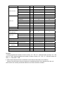
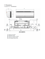
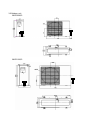
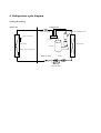
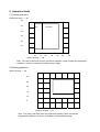
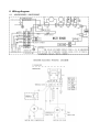
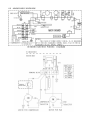
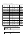
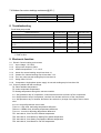
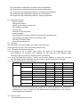
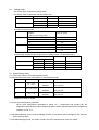
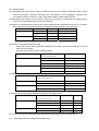
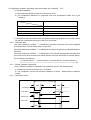
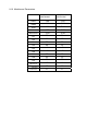
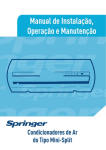
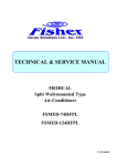
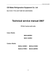
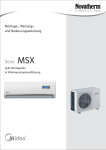
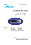
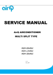
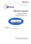
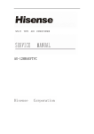
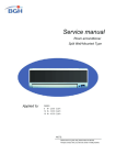
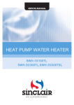
Service Manual
Split Wall-Mounted Type
Room Air Conditioner
(ALLEGRO PLUS SERIES)
Model applied:
42HQE009QC/38YE009QC
42HQE012QC/38YE012QC
Contents
1.
2.
3.
4
5
6
7
8
9
Features .......................................................................................................................3
Specification ................................................................................................................4
Dimensions ..................................................................................................................6
Refrigeration cycle diagram .......................................................................................9
Operation limits .........................................................................................................10
Wiring diagram .......................................................................................................... 11
Specification of electrical parts................................................................................13
Troubleshooting ........................................................................................................14
Electronic function ....................................................................................................14
1. Features
1.1 Compact design.
1.2 Quiet operation.
1.3 Anti-icing function at cooling mode.
1.4 Anti-cold air function at heating mode.
1.5 Auto-defrosting and heating recovering function at heating mode.
1.6 Outdoor unit overload current protection.
1.7 Restart function.
1.8 24 hours on/off mode time setting.
1.9 Error self diagnosis function.
1.10
Quickly connected piping and cable
2. Specification
Model
Power supply
Cooling
Ph-V-Hz
1, 220-240V~, 50Hz
1, 220-240V~, 50Hz
Capacity
w
2500
3500
Rated Input
W
890
1250
Rated current
A
4.2
5.5
W/W
2.81
2.81
EER
Heating
42HQE009QC/38YE009QC 42HQE012QC/38YE012QC
Capacity
w
2900
4000
Rated Input
W
900
1250
4.2
5.4
3.21
3.21
Rated current
COP
A
W/W
Moisture Removal
L/h
1.0
1.2
Max. input consumption
W
1200
1500
Max. current
A
6
8
Starting current
A
21.7
33
Model
PA108X1C-4DZDE
PA145X2C-4FT
Type
Rotary
Rotary
Brand
TOSHIBA
TOSHIBA
Btu/h
8820
12045
Input
W
900
1225
Rated current(RLA)
A
4.1
5.5
B160-135-241E/MRA
UP3RE0591-T56
13430-9087
(INTERNAL:IOL)
Capacity
Compressor
Thermal protector
Indoor fan motor
Capacitor
uF
25
35
Refrigerant oil
ml
350
480
Model
RPG13H
RPG20D
Brand
Welling
Welling
Input
W
36.5
44
Capacitor
uF
1.2
1.5
r/min
1150/1050/950
1180/900/750
2
2
Speed(hi/mi/lo)
a.Number of rows
Indoor coil
b.Tube pitch(a)xrow pitch(b)
mm
21x13.37
21x13.37
c.Fin spacing
mm
1.3
1.3
Hydrophilic aluminium
Hydrophilic aluminium
d.Fin type (code)
e.Tube outside dia.and type
mm
f.Coil length x height x width
mm
Type
Indoor air flow (Hi/Mi/Lo)
Indoor Sound pressure (Hi/Mi/Lo)
Indoor unit
tube
φ7,
innergroove
2
2
mm
Crossflow
Crossflow
m3/h
450/400/350
642/470/380
38/36/33
41/36/30
Dimension (W*H*D)
mm
750x250x188
815X280X195
Packing
mm
830x336x280
915X360X275
(W*H*D)
tube
655×315×26.74
dB(A)
(LPA) @cooling
innergroove
578X252X26.74
g.Number of circuits
Indoor fan
φ7,
Net/Gross weight
Outdoor fan motor
Kg
12.5/15
14/19.5
Model
YDK24-6T
YDK24-6F
Brand
Welling
Input
W
56
56
Capacitor
uF
3
2.5
r/min
840
800
1
1.6
Speed
a.Number of rows
Outdoor coil
b.Tube pitch(a)xrow pitch(b)
mm
25.4x22
21x13.37
c.Fin spacing
mm
1.4
1.5
Hydrophilic aluminium
Hydrophilic aluminium
d.Fin type (code)
e.Tube outside dia.and type
mm
f.Coil length x height x width
mm
φ7,
innergroove
tube
4
mm
Propeller
Propeller
m3/h
1800
2000
dB(A)
53
54
Dimension(W*H*D)
mm
700X540X225
780X540X245
Packing
mm
815X580X325
910X575X335
Kg
27/30
34.5/36.5
g
850
1000
MPa
4.2
4.2
Quick Connection(4m)
Quick Connection(4m)
Outdoor Sound pressure
(LPA) @cooling
(W*H*D)
Net/Gross weight
R410A
Design pressure
Refrigerant piping
tube
2
Outdoor air flow
Refrigerant type
innegroove
775x504x26.74
Type
Outdoor unit
φ9.53
684x508x22
g.Number of circuits
Outdoor fan
WELLING
Liquid side/ Gas side
Expansion device
Main
mm
Φ2.5*1.3*700
Φ3.2*1.7*1100
(Capillary)
Sub
mm
Φ2.5*1.3*950
Φ2.5*1.5*1100
Operation temp
℃
17-30
17-30
Ambient temp
℃
-7-43
-7-43
Application area
m2
14-21
18-26
Remarks:
1.Cooling capacities are based on indoor air temp. 27℃ DB, 19℃ WB and outdoor air temp. 35℃ DB,
and 24℃ WB. Heating capacities are based on indoor air temp. 20℃ DB, 15℃ WB and outdoor air
temp. 7℃ DB, and 6℃ WB.
2. Indoor Sound Pressure level is measured in free field (JIS 9612 std) at 1m distance.
Outdoor Sound Pressure level is measured in hemispherical field, at 4m distance from the unit.
these values are normally somewhat different as a result of ambient condition.
3. Dimensions
3.1 Indoor unit
42HQE009QC
Indoor unit
42HQE012QC
3.2 Outdoor unit
38YE009QC
38YE012QC
4 Refrigeration cycle diagram
Cooling & heating
Indoor unit
outdoor unit
Quick connecter
Auxiliary accumulator for 12K
Sensor of room temp
.
4 way valve
Heat exchanger
Heat exchanger
Compressor
Sensor of heat exchanger temp
Accumulator
.
Quick connecter
Capillary
One way valve
5 Operation limits
5.1 Cooling operation
Outdoor air temp. ℃ DB
45
40
DRY
COOLING
35
30
25
20
10
15
20
Indoor air temp. ℃ DB
25
30
35
40
Note : The chart is the result from the continuous operation under constant air temperature
conditions. However, excludes the initial pull-down stage.
5.2 Heating operation
Indoor air temp. ℃ DB
30
25
20
15
10
5
-5
5
15
25
Outdoor air temp.℃ DB
Note : The chart is the result from the continuous operation under constant air
temperature conditions. However, excludes the initial pull-down stage.
6 Wiring diagram
6.1 42HQE009QC / 38YE009QC
6.2 42HQE012QC/ 38YE012QC
7 Specification of electrical parts
7.1 Temperature-resistance of room temp. sensor & pipe temp. sensor
Temperature
℃
Resistance
KΩ
Temperature
℃
Resistance
KΩ
Temperature
℃
Resistance
KΩ
-10
62.28
17
14.618
44
4.3874
-9
58.71
18
13.918
45
4.2126
-8
56.37
19
13.263
46
4.0459
-7
52.24
20
12.643
47
3.8867
-6
49.32
21
12.056
48
3.7348
-5
46.57
22
11.5
49
3.5896
-4
44
23
10.973
50
3.451
-3
41.59
24
10.474
51
3.3185
-2
39.82
25
10
52
3.1918
-1
37.2
26
9.5507
53
3.0707
0
35.2
27
9.1245
54
2.959
1
33.33
28
8.7198
55
2.8442
2
31.56
29
8.3357
56
2.7382
3
29.91
30
7.9708
57
2.6368
4
28.35
31
7.6241
58
2.5397
5
26.88
32
7.2946
59
2.4468
6
25.5
33
6.9814
60
2.3577
7
24.19
34
6.6835
61
2.2725
8
22.57
35
6.4002
62
2.1907
9
21.81
36
6.1306
63
2.1124
10
20.72
37
5.8736
64
2.0373
11
19.69
38
5.6296
65
1.9653
12
18.72
39
5.3969
66
1.8963
13
17.8
40
5.1752
67
1.830
14
16.93
41
4.9639
68
1.7665
15
16.12
42
4.7625
69
1.7055
16
15.34
43
4.5705
70
1.6469
7.2 Compressor windings resistance (run & start winding @20℃)
Compressor model
Winding 1 (Main)
PA108X1C-4DZDE
3.75±5% Ω
PA145X2C-4FT
2.35±5% Ω
Winding 2 (Sub)
4.75±5% Ω
3.22±5% Ω
7.3 Indoor fan motor windings resistance (@20℃).
Motor model
Winding 1 (Main)
RPG13H
385±8%Ω
RPG20D
360±8%Ω
Winding 2 (Sub)
400±8%Ω
291±8%Ω
7.4 Outdoor fan motor windings resistance(@20℃).
Motor model
Winding 1 (Main)
YDK24-6T
170±8%Ω
YDK24-6F
440±8%Ω
Winding 2 (Sub)
195±8%Ω
215±8%Ω
8 Troubleshooting
For all heat pump model
Failure phenomenon
Operation lamp
Timer lamp
Defrosting lamp
Over current protection of the compressor occurs 4 times
☆
X
☆
Indoor fan speed has been out of control for over 1 minute
X
☆
☆
No over-zero signal
☆
☆
☆
X
X
☆
X
☆
X
On
☆
X
Temp. sensor on indoor evaporator is open circuit or short
circuit
Indoor room temp. sensor is open circuit or short circuit
EEROM error
r Extinguish
☆ Flash at 5Hz
9 Electronic function
9.1 Electric Control working environment
9.1.1 Input voltage: 175~253V
9.1.2 Input power frequency:50Hz
9.1.3 Ambient temperature: -7°C~+43°C
9.1.4 Indoor fan normal working amp is less than 1A,
9.1.5 Outdoor fan. Normal working amp is less than 1.5A
9.1.6 Four-way valve normal working amp is less than 1A.
9.1.7 Swing motor: DC12V.
9.1.8 Compressor: single-phase power supply. Its normal working amp is less than 15A
9.2 Proper symbols and their meanings:
TA: Indoor ambient temperature
TE: Indoor evaporator temperature
TS: Setting temperature through the remote controller
I3sec: Self-protection amp of compressor, continue three seconds until turns off the compressor.
I5MIN: Self-protection amp of compressor, continue five minutes until turns off the compressor.
IFAN: Self-protection amp of outdoor fan/indoor fans when they change from higher wind to lower
wind.
IRESTORE: Amp self-protection return value
THDEFROST: High wind, defrosting temperature difference
TMDEFROST: Middle wind, defrosting temperature difference
TLDEFROST: Low wind, defrosting temperature difference
TE1: Anti-cold air, from Fan Off to Breeze temperature
TE2: Anti-cold air, from Breeze to Setting Fan Speed temperature
TE3: Anti-cold air, from Setting Fan Speed to Breeze temperature
TE4: Anti-cold air, from Breeze to Fan Off temperature
TE5: Evaporator low temperature protection entering temperature
TE6: Evaporator low temperature protection restoring temperature
TE7: Evaporator high temperature protection, compressor off temperature
TE8: Evaporator high temperature protection, fan off temperature
TE9: Evaporator high temperature protection, restoring temperature
9.3 Systematic functions
Remote receiving
Testing and forced run
Position set for indoor unit wind vane
LED displaying and alarm
On or off Timer
Protection for the compressor
Current protection
High temperature protection of indoor heat exchanger at heating mode
Auto defrosting and heating recovery at heating mode
Anti cold air at heating mode
Anti frozen at heating mode
9.4 Protection
The compressor functions protection with a delay of three minutes.
Sensor protection at open circuit and breaking disconnection
9.4.1 Temperature Fuse break protection
9.4.2 Fan Speed is out of control. When Indoor Fan Speed is too high(higher than High
Fan+300RPM)or too low(lower than 400RPM), the unit stops and LED displays failure
information and can’t returns to normal operation automatically.
9.4.3 Cross Zero signal error warning. If there is no Cross Zero signals in 4 minutes, the unit stops
and LED displays failure information and can’t returns to normal operation automatically.
9.4.4 The current protection of the compressor
Condition
Current up
Current down
Indoor fan
Compressor
Outdoor fan
Remark
I< IRESTORE
On
On
On
IRESTORE <I< IFAN
On
On
Off
Heating mode
Low speed
On
On
Cooling mode
IFAN <I<I5MIN
Off
Off
After 5 Minutes
I5MIN<I< I3SEC
Off
Off
After 3 Seconds
I5MIN<I< I3SEC
Off
Off
After 3 Seconds
IFAN <I<I5MIN
Off
Off
After 5 Minutes
On
On
Off
Heating mode
Low speed
On
On
Cooling mode
On
On
On
IRESTORE <I< IFAN
I< IRESTORE
If compressor turns off for continuously 4 times due to current protection in 5 minutes since
Compressor On, the unit stops and LED displays failure information and can’t returns to
normal operation automatically.
9.5 Fan-only mode
Fan speed is high/mid/low/ Auto
9.6
Cooling mode
The 4-way valve is closed at cooling mode.
The action of the compressor and the outdoor fan:
Condition
Temp. up
Temp. down
Compressor
Outdoor fan
T>Ts+1
On
On
T<Ts+1
Off
Off
T>Ts
On
On
T<Ts
Off
Off
Auto fan at cooling mode:
Condition
Indoor fan speed
T=Indoor Temp.-Setting Temp.
Temp. up
Temp. down
T<3
Low
3 <T<5
Mid.
T>5
High
T>3
High
1 <T<3
Mid.
T<1
Low
Anti-freezing control to indoor evaporator at cooling mode( T: evaporator temp. )
Condition
Temp.
Temp. up
Compressor
T> TE6
T< TE6
Temp. down
On
>5 Minutes
T> TE5
T< TE5
Outdoor fan
Time
>5 Minutes
On
Off
Off
On
On
Off
Off
9.7 Dehumidifying mode
9.7.1 The 4-way valve is off in dehumidifying mode
9.7.2 Compressor and Indoor Fan actions in dehumidifying mode
NO
Conditions
1
TA ≥TS+2
2
TS ≤TA<TS+2
3
TA < TS
Indoor Fan
Compressor and Outdoor Fan
LOW
ON 6minutes
BREEZE
OFF 4minutes
LOW
ON 5minutes
BREEZE
OFF 5minutes
LOW
ON 4minutes
BREEZE
OFF 6minutes
Repeat on and off cycle.
9.7.3 Low room temperature protection:
When room temperature decreases to below 10 ℃ , compressor and outdoor fan will
stop(indoor fan is Breeze). Dehumidifying operation will be resumed when room temperature
restores to over 13℃.
9.7.4 At dehumidifying mode, the anti-freezing function of the indoor heat exchanger is the same as
that of cooling mode.
9.7.5 At dehumidifying mode, the action of indoor fan is the same as that of air-only mode.
9.8 Heating mode
9.8.1 Generally, the 4-way valve is open in heating mode, but it is closed in defrosting mode. 4-way
valve must delay 2 minutes compared with compressor if the compressor changed into
non-heating mode or turned off. 4-way valve doesn't delay in dehumidifying mode.
9.8.2 Generally, the outdoor fan is turned off with the on-off action of compressor in heating mode,
except for the defrosting mode or the end of defrost.
9.8.3 Action of compressor and outdoor fan motor at heating mode: compressor must run for 7 minutes
after starting and then judge temperature. Meanwhile other protections are still valid.
Condition
Room temp. up
Room temp. down
Compressor
Outdoor fan
T> Ts+3
Off
Off
T<Ts+3
On
On
T< Ts+2
On
On
T>Ts+2
Off
Off
9.8.4 Indoor Fan actions at heating mode
Indoor Fan can be set at HIGH/MID/LOW/AUTO by using a remote controller, but Anti-cold
wind function prevails.
Anti-cold wind control function at heating mode
Condition
Indoor fan speed
T= Indoor exchanger temp.
Indoor exchanger temp. up
Indoor exchanger temp. down
T<TE1
Off
TE1<T<TE2
Breeze
T>TE2
Setting fan speed
T> TE3
Setting fan speed
TE3<T<TE4
Breeze
T<TE4
Off
9.8.5 Auto wind at heating mode
Condition
Indoor fan speed
T=Indoor Temp.-Setting Temp.
Room
Room
temp. up
temp. down
T<2
High
T>2
Mid.
T>0
Mid.
T<0
High
9.8.6 Indoor evaporator high-temperature protection at heating mode
Condition
Compressor
Outdoor fan
T= Indoor exchanger temp.
Indoor exchanger temp. up
Indoor exchanger temp. down
T<TE8
On
On
TE8<T<TE7
On
Off
T>TE7
Off
Off
T>TE9
Off
Off
T<TE9
On
On
9.8.7 The louver opens to Standard Angle ANGLHEAT when power is on for the first time
9.9
Defrosting operation (Available for heating only).
9.9.1 Defrosting condition: Defrosting starts when either of the following ①&②:
① A and B are satisfied:
A: The compressor keeps running for 40 minutes or more.
B: The temperature difference of evaporator and room temperature meets one of the
following:
Temp. of evaporator-room temp.
℃
Fan speed is high
≤THDEFROST
Fan speed is mid
≤TMDEFROST
Fan speed is low
≤TLDEFROST
Breeze
Meet only if it is Breeze
② Calculate from the end of latest defrost, evaporator high temp. protection only closes outdoor
fan with the compressor still running. Add up to 90 minutes.
9.9.2 Defrosting time
If the temp. difference condition ① is satisfied for less than 40 minutes, this can be regarded
as severe frosting. The defrosting time is 10 minutes.
If the temp. difference condition ② is satisfied for more than 40 minutes, the defrosting time is
6 minutes.
If the temp. difference condition ① is satisfied out of 40 minutes, generally the defrosting time
is 6 minutes, after three continuous 6-minute defrost, the fourth should be 10 minutes defrost.
The circulation is as following:
→6-minute defrost → 6-minute defrost→6-minute defrost→10-minute defrost→
9.9.3
9.9.4
Ending condition of defrosting
If one of following conditions is satisfied, end the defrost and turn into heating mode:
A. The defrost time has reached to 6 or 10 minutes.
B. The compressor current has reached to IDEFROST or above,
models.
Defrosting Actions:
Defrost 10or 6minutes
45S
25S
Compressor
23S
4-way Valve
40S
Outdoor Fan
Indoor Fan
10S
IDEROST differs in different
9.10 Automatic operation mode
9.10.1 The air conditioner automatically selects one of the following operation modes: cooling,
heating or fan only according to the temp. difference between room temp. (TA) and set temp.
(TS).
TA—TS
Operation mode
TA—TS>2℃
Cooling
-1℃≤TA—TS≤+2℃
Fan-only
TA—TS<-1℃
Heating (Fan-only for cooling only type)
9.10.2 The indoor fan blows automatically in corresponding selected mode.
9.10.3 The motion of indoor fan’s blade should accord with the selected operation mode.
9.10.4 One mode should be carried out for at least 15 minutes once selected. If the compressor
cannot start for 15 minutes, reselect the operation mode according to the room temp. and set
temp., or reselect when the set temp. varies.
9.11 Forced cooling function
9.11.1 Select forced cooling function with the forced cooling button or the switch.
9.11.2 The compressor is unconditionally turned on, after 30 minutes cooling operation whose fan
mode is set as low, the A/C operates at the DRY mode with a set temp. of 24℃.
9.11.3 All protections of remote control cooling are available at forced cooling operation.
9.12 Forced Auto function
Select forced auto function with the forced auto button or the switch.
In forced auto status the A/C operates like auto mode with a set temp. of 24℃.
9.13 Timer Function
9.14 Economic Running
9.14.1 The economic running function is available at cooling, heating or auto mode.
Cooling:
The set temperature rise 1℃ per hour. Two hours later, the set temperature will maintain as
a constant and the fan speed is kept at low speed.
Heating:
The set temperature decrease 1℃ per hour. Two hours later, the set temperature will
maintain as a constant and the air circulation is kept at low speed (Anti-cold air function takes
precedence over all).
Auto:
The economic running function operates in accordance with selected running mode by auto
mode.
9.15 Auto restart function
In case of a sudden power failure, this function automatically sets the unit to previous settings
before the power failure when power returns.
9.16 Models and Parameters
Model
42HQE009QC
38YE009QC
42HQE012QC
38YE012QC
I3SEC
10A
12A
I5MIN
8A
8.5A
IFAN
6.5A
7.5A
IRESTORE
4.5A
6.5A
IDEFROST
3.5A
5.0A
TE1
28
34
TE2
32
37
TE3
30
33
TE4
26
22
TE5
4
2
TE6
10
7
TE7
60
62
TE8
53
53
TE9
50
52
THDEFROST
15
15
TMDEFROST
16
16
TLDEFROST
17
17