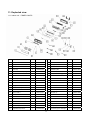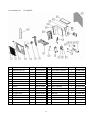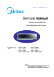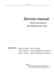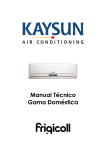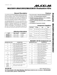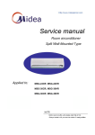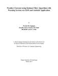
1
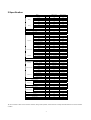
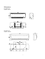
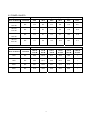
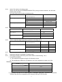
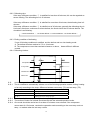
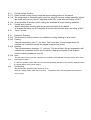
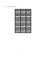
TECHNICAL & SERVICE MANUAL
MEDICAL
Split Wall-mounted Type
Air-Conditioner
FSMED-74HFPL
FSMED-124HFPL
FI-SM-040902
NOTICE
Specifications are subject to change without notice for further improvement.
All the product information has been carefully checked.
Contents
1. Features………………………………………………………………… 2
2. Specification………………………………………………………..…… 3
3. Dimensions………………………………………………………….….. 4
4. Refrigeration cycle diagram…………………………………………… 6
5. Operation range
………….……………………………………….…...6
6. Pressure table…………….……………………………………… .…... 7
7. Capacity table………………………………………………… ……….. 9
8. Wiring diagram…………………………………………………..…..… 11
9. Electronic function………………………………………….………… 14
10. Troubleshooting………………………………………………………. 21
11. Characteristic of temp. sensor……………………………………… 24
12. Expolded view………………………………………………………… 25
1
1.Features
1.1 Compact design
1.2 High efficiency and quiet operation
1.3 A class energy level
1.4 Refrigerant R410A
1.5 Bio Filter and Plasma Filter
2
2.Specification
FSMED-74HFPL
FSMED-124HFPL
Ph-V-Hz
1, 220-240V~, 50Hz
1, 220-240V~,
Capacity
W
2150
3600
Input
W
640
1120
Rated current
A
2.8
5.0
3,36
3,22
Model
Power supply
Cooling
EER
Heating
Capacity
W
2500
4400
Input
W
690
1180
Rated current
A
3.0
5.3
COP
W/W
3.62
3.73
Moisture Removal
L/h
0.7
1.2
Max. input consumption
W
1000
1550
Max. current
A
4.5
8
Starting current
A
16
30
Model
PA82X1C-4DZ2
PA145X2C-4FT
Type
Rotary
rotary
6680
12000
1200
Compressor
Capacity
Btu/h
Input
W
675
Rated current(RLA)
A
3.11
5.6
Locked rotor Amp(LRA)
A
15.0
29.9
UP3QE0591-T71
UP3RE0591-T56
Thermal protector
Capacitor
uF
25
35
Refrigerant oil
ml
350
480
Model
RPG13H
RPG20D
Input
W
36.5
51.5
Capacitor
uF
1.2
1.5
Speed(hi/mi/lo)
r/min
1050/9200/820
1250/1000/800
Indoor fan motor
Indoor coil
Number of rows
2
2
Fin type (code)
Hydrophilic aluminium
Hydr0philiC
Tube outside dia.and type
mm
φ7,
innergroove
Number of circuits
Indoor air flow (Hi/Mi/Lo)
m3/h
Indoor noise level (Hi/Mi/Lo)
Indoor unit
innergroove
2
450/400/350
650/520/420
dB(A)
34/32/30
39/33/28
Dimension (W*H*D)
mm
750*250*205
815*280*215
Packing
mm
830X285X335
915X290X360
Kg
8,5/10,5
10,5/12,5
YDK24-6T
YDK36-6
(W*H*D)
Net/Gross weight
Model
Outdoor fan motor
Outdoor coil
φ7,
2
Input
W
56
68
Capacitor
uF
2.5
2.5
Speed
r/min
800
900
Number of rows
2
2
Fin type (code)
Hydrophilic aluminium
Hydrophilic
Tube outside dia.and type
mm
Ф7,innergroove tube
Ф9.53,innergroove
Coil length x height x width
mm
750x508x26.74
680x550x44
Number of circuits
Outdoor air flow
m3/h
Outdoor noise level
2
2
1500
1900
dB(A)
49
52
Dimension(W*H*D)
mm
700X535X235
760X590X285
Packing
mm
815X580X325
890X655X360
Kg
32/35
41.5/45.5
Refrigerant type R410A
g
820
1170
Design pressure
MPa
4.2
4.2
Liquid side/ Gas side
mm(inch)
Ф6.35/Ф9.53
Ф6.35/Ф12.7
Max. refrigerant pipe length
m
10
10
Max. difference in level
m
5
5
No
No
Outdoor unit
(W*H*D)
Net/Gross weight
Refrigerant piping
Connection wiring
Plug type
16A
16A
Thermostat type
Electrolic control
Electrolic control
Operation temp
℃
Ambient temp
℃
17-30
18-43
/
-7 -24
17-30
18-43
/
-7 -24
★1 The noise date is base on hemi-anechoic chamber, during actual operation, these values are normally somewhat different as a result of ambient
condition.
3
3.Dimensions
3.1 Indoor unit
FSMED-74HFPL
3.2 Indoor unit
FSMED-124HFPL
4
3.3 Outdoor unit
FSMED-74HFPL
3.4 Outdoor unit
FSMED-124HFPL
750
590
285
290
315
62
530
5
110
4.Refrigeration cycle diagram
5.Operation range
6
6. Pressure table
Note:
*The pressure data is from 3 way valve, the pressure data are pressure above atmosphere.
*D: Dry bulb temp.
*W: Wet bulb temp.
6.1 FSMED-74HFPL
Cooling mode
Indoor
Conditions
Outdoor temperature (Dry bulb temp)
Pressure
25ºC
30ºC
35ºC
40ºC
45ºC
50ºC
21ºC D
15ºC W
bar
6.1
6.7
7.1
7.9
8.4
9.4
24ºC D
17ºC W
bar
6.2
6.4
7.4
7.9
8.6
9.4
27ºC D
19ºC W
bar
6.0
6.8
7.4
8.1
9.0
9.9
32ºC D
23ºC W
bar
6.9
7.2
7.7
8.2
9.1
10.0
OUTDOOR CONDITIONS
Heating mode
Indoor Conditions
Pressure
12ºC D
7ºC D
0ºC D
-4ºC D
-7ºC D
-15ºC D
11ºC W
6ºC W
-1ºC W
-6ºC W
-9ºC W
-xºC W
15ºC
bar
23.5
23.0
23.0
22.5
23.2
/
18ºC
bar
21.5
23.0
20.7
21.0
20.5
/
20ºC
bar
22.0
22.3
21.0
21.3
20.5
/
22ºC
bar
23.5
23.1
21.0
21.3
20.5
/
7
6.2 FSMED-124HFPL
Cooling mode
Indoor Conditions
21ºC D
15ºC W
24ºC D
17ºC W
27ºC D
19ºC W
32ºC D
23ºC W
Outdoor temperature (Dry bulb temp)
Pressure
25ºC
30ºC
35ºC
40ºC
45ºC
50ºC
bar
8.3
8.4
8.7
8.8
9.3
9.8
bar
8.5
8.7
9.1
9.3
9.9
10.3
bar
8.7
9.1
9.3
9.7
10.2
10.8
bar
9.1
9.5
9.8
10.3
10.7
11.1
OUTDOOR CONDITIONS
Heating mode
Indoor Conditions
Pressure
12ºC D
7ºC D
0ºC D
-4ºC D
-7ºC D
-15ºC D
11ºC W
6ºC W
-1ºC W
-6ºC W
-9ºC W
-xºC W
15ºC
bar
26.9
25.4
21.7
20.9
19.5
/
18ºC
bar
29.3
26.7
23.3
21.5
20.6
/
20ºC
bar
29.7
28.6
23.7
23.1
21.6
/
22ºC
bar
31.9
39.6
24.9
23.5
22.2
/
8
7. Capacity table
FSMED-74HFPL
SUMMER
OUTDOOR TEMPERATURE DRY
Indoor
25ºC
30ºC
35ºC
40ºC
45ºC
50ºC
Total capacity kW
2.04
1.94
1.70
1.61
1.53
1.41
Sensitive capacity kW
1.52
1.41
1.39
1.32
1.19
1.07
Input kW.
0.53
0.58
0.60
0.67
0.73
0.80
Total capacity kW
2.14
2.05
1.93
1.81
1.73
1.51
Sensitive capacity kW
1.61
1.46
1.45
1.54
1.23
1.15
Input kW.
0.54
0.60
0.62
0.70
0.74
0.82
Total capacity kW
2.31
2.24
2.05
1.95
1.70
1.65
Sensitive capacity kW
1.78
1.65
1.54
1.43
1.26
1.28
Input kW.
0.57
0.62
0.64
0.71
0.75
0.83
Total capacity kW
2.33
2.36
2.31
2.25
2.15
2.03
Sensitive capacity kW
1.83
1.67
1.65
1.64
1.57
1.52
Input kW.
0.58
0.64
0.66
0.73
0.80
0.86
Conditions
21ºC D
15ºC W
24ºC D
17ºC W
27ºC D
19ºC W
32ºC D
23ºC W
WINTER
OUTDOOR CONDITIONS
Indoor
12ºC D
7ºC D
4ºC D
0ºC D
-4ºC D
-7ºC D
Conditions
11ºC W
6ºC W
3ºC W
-1ºC W
-6ºC W
-8ºC W
Capacity kW
3.01
2.73
2.47
1.76
1.65
1.58
Input kW.
0.76
0.66
0.60
0.58
0.50
0.45
Capacity kW
2.86
2.64
2.34
1.69
1.53
1.41
Input kW.
0.78
0.67
0.62
0.59
0.62
0.47
Capacity kW
2.77
2.49
2.28
1.62
1.59
1.33
Input kW.
0.81
0.69
0.64
0.59
0.53
0.48
Capacity kW
2.61
2.43
2.13
1.58
1.26
1.17
Input kW.
0.83
0.68
0.65
0.60
0.56
0.51
15ºC
18ºC
20ºC
22ºC
9
FSMED-124HFPL
SUMMER
OUTDOOR TEMPERATURE DRY
Indoor
25ºC
30ºC
35ºC
40ºC
45ºC
50ºC
Total capacity kW
3276
3187
3105
2821
2746
2621
Sensitive capacity kW
2567
2457
2413
2287
2210
2087
Input kW.
890
1010
1082
1188
1243
1337
Total capacity kW
3663
3503
3315
3148
3076
2932
Sensitive capacity kW
2918
2766
2725
2557
2453
2334
Input kW.
915
1033
1121
1228
1278
1367
Total capacity kW
3860
3700
3626
3371
3215
3125
Sensitive capacity kW
3039
2913
2832
2645
2567
2419
Input kW.
944
1048
1120
1253
1312
1426
Total capacity kW
4215
4100
3845
3601
3501
3313
Sensitive capacity kW
3120
2939
2891
2715
2589
2503
Input kW.
969
1088
1189
1302
1349
1455
Conditions
21ºC D
15ºC W
24ºC D
17ºC W
27ºC D
19ºC W
32ºC D
23ºC W
WINTER
OUTDOOR CONDITIONS
Indoor
12ºC D
7ºC D
4ºC D
0ºC D
-4ºC D
-7ºC D
Conditions
11ºC W
6ºC W
3ºC W
-1ºC W
-6ºC W
-8ºC W
Capacity kW
4446
4264
4132
3838
3335
305
Input kW.
1141
1106
1059
1035
895
812
Capacity kW
4380
4248
3954
3761
3258
2948
Input kW.
1188
1153
1142
1082
953
918
Capacity kW
4261
4153
3877
3683
3189
2871
Input kW.
1224
1180
1129
1082
976
941
Capacity kW
4106
3989
3761
3567
3045
2876
Input kW.
1259
1212
1153
1106
1000
836
15ºC
18ºC
20ºC
22ºC
10
8. Schematic diagram and wiring diagram
8.1 Schematic diagram
2
IN4007*4
IC1
1
CN1
Vin
D2
A
E1
D3
C1
B
3
Vout
IC3
Vin
C3
E2
4
104
2
D4
2200uF/25V
IN4007*4
1
D17
D
E10
Vin
Vout
GND
D16
C
1000uF/16V
+12V-b
3
IC10 7812
C23
REC
470uF/16V
R20
1K
REC1
D13
IN4148 +12V-a CN4
REC
V
C10
C11 GND
E7
102
104
FANSP_FEEDBACK
RECEIVER_V
10uF/16V
COM1
COM3
+5V
R42
2K
R41
R41
R41
10K
10K
10K
104
2
R215.1K
C12
103
COM2
+5V
R41
2K
+5V
C24
E11
104
D18
Q2
9014
C9
104
8
7
R19 150
+5V
R15R17
12K12K
D11 1N4148
D12 1N4148
B
TRANS
D
ZERO
R16 12K
A
C4
E3
6
+5V
+5V
3
Vout
104
104
5
R18 10K
+5V
7805
2
4
3
2
1
3
+12V-a
1
7812
GND
D1
GND
1
3
2
1
FAN_BACK
D
R43
2K
D19
1000uF/16V
2200uF/25V
+5V
GNDB
R4 12K
Q10
Q9
Q8
+5V
1
IC5 KIA7042
C26
104
2
+12V
JR8
10K
R5
1K
FAN_IN
HEAT
BUZ1
BUZZER1
BUZ '
+5V
STEP_I1
STEP_I2
C
STEP_I3
R38
10K
STEP_I4
SW_TEST
R39
C22
104
5.1K
FAN_IN
3
BUZ
4
STEP_I1
5
STEP_I2
6
STEP_I3
7
STEP_I4
8
BUZ
JR9
10K
COMP
COMP
JR1
9
10
10K
HEAT
11
SEG1
12
SEG2
13
SEG3
14
SEG4
15
SW1
SEG1
SEG2
SEG3
SEG4
16
+5V
17
CN2
+5V
R59 R60
10K 10K
2
D5
IN4148
1
B
T1_room
R10
2K
T1_room
D6
R8
8.1K/1%
IN4148
CN3
C6
E4
T1
18
T2
19
T1_room
T2_I.pipe
+5V
CURRENT 20
Current
AUTO_SELECT 21
AUTO_SELECT
P25
RESET
P26
XT1
P00
XT2
P01
Vpp/IC
1
T2_I.pipe
31 COM3
P33
30 FAN_OUT
P31
28 ZERO
AVDD
P30
27 REC
AVREF
P11
26 VALVE
2
D8
C7
E5
10uF/16V
104
8
R23 2K
AUTO_SELECT
D9
1N4148
R14
1.4K/1%
E6
10uF/16V
R13
16K
C13
104
FAN_OUT
CT1
0057h
Q3
FRESH
24
22 SW
6
5
Q2
Dsb
Q1
Dsa
Q0
VALVE
SW_TEST
4
3
JR4
10K
JR5
10K
JR2
10K
JR3
10K
LOAD_HEAT L
LED6
R47 330
D22
IN4148
LED7
R48 330
LED9
R54 330
Q5
9014
R33
HEAT
1
LOAD_FAN OUT
R63
+12V-a PC817
9014
IN3
OUT3
L1
GNDB
Q6
9014
IN4
OUT4
IN5
OUT5
IN6
OUT6
IN7
OUT7
VSS
VDD
3
13
12
11
10
2K
CN12
2
14
+12V-a
LOAD_VALVE
4
FAN_IN '
C20
333
RY5
RELAY-SPST
D24
5
+12V-a SWING
BUZ '
IN4148
COMP '
Q7
9014
R35
9
VALVE
2K
UJN2003
3.15A/250V
+12V-a
R25 51/1W
C15
L1
333
T2
T1
BT131
TR1
C14
1.2uF/450V
5
E9
470uF/25V
?
L2
Z1
12V
R28
11K/2W
IC6 PC817
10D471K
2
t
N
CN14
1
N
5
11
0.1uF/275VAC
D15
FAN_IN '
4
C23
1
CN11
1
LOAD_COMP
C21
CN15
ZR1
R29
11K/2W
IN4007
+12V-a
R26
1K
3
R36
51/1W
L1
FUSE1
+12V-a
4
B
IN4148
+12V-b
1
15
2
RY4
RELAY-SPST
R34
OUT2
1
D23
Q12
5.1K
CN13
+12V-a
2
IC9
1K
FAN_OUT
16
OUT1
IN2
10A
CN16
+12V-b
Q11
FUSE2
2K
SW2
R62
1
HEAT_L
RY3
RELAY-SPST
LED8
R49 330
R55 330
R61
2K
CN10
+12V-a
R46 330
9014
FAN_IN
2
CP
R45 330
+5V
2K R24
1
1
Q4
74HC164
REC
25 FRESH
12
11
10
C
2K
R44 330
1
3
D10
1N4148
R6
1K/1%
SEG4
C17
102
FANSP_FEEDBACK
2
Current
C8
104
C19
104
CN6
JR7
10K
7
COMP
+5V
R12 2K
6
BUZ
JR6
10K
A
5
FAN_IN
+5V
IN4148
4
STEP_I4
T2_I.pipe
R9
8.1K/1%
3
C16
102
2
N
Q3
9014
R27
13
Q6
MR
23
AN14
AN13
Vcc
8
SEG3
1
HEAT_N
RY2
RELAY-SPST
Q7
GND
9
+5V
ZERO
P10
AVSS
LOAD_HEAT N
D21
Q5
COM3
29 FANSP
P32
P53
AN15
104
CN9
+12V-a
Only For Heat Pump
IN4148
COM2
+5V
P52
7
C24
14
COM1
P20
STEP_I3
R11 2K
34 COM1
33 COM2
32
P50
AN12
104
1
2
3
4
IC8
SDA
VDD1
STEP_I2
D7
IN4148
SCL
P05
AN11
A0
A1
A2
GND
24C04
36 SCL
AN10
VCC
WC
SCL
SDA
37
35 SDA
P51
8
7
6
5
SCL
SDA
38
P24
P22
IC2
R1 R2
10K 10K
RST
P23
P21
DIS1
WT4021BG
C2
+5V
4M
40 RST
P03
VSS1
X1
39
P02
P04
R7
1M
41 X2
X2
VDD0
+5V
2
42 X1
X1
VSS0
UPD789166
IC7
1
STEP_I1
IN1
104
10uF/16V
9012
IC4
1
+5V
com1
com2
h
g
f
e
d
c
b
a
RST
C25
104
2
9012
9012
FRESH
3
G
C5
104
A
RY6 333
COMP
COMP '
TRANS_IN
PTC
82RM
R37
51/1W
L(POWER_IN PORT)
N
6
7
8
8.2 Wiring diagram
FSMED-74HFPL
Indoor unit
outdoor unit
12
FSMED-124HFPL
Indoor unit
outdoor unit
13
9 Electronic function
9.1
Electric Control working environment
9.1.1
input voltage: 175~253V
9.1.2
Input power frequency:50Hz
9.1.3
Ambient temperature:
18-43 /
-7°C~+43°C
9.1.4
Indoor fan normal working amp is less than 1A,
9.1.5
Outdoor fan. Normal working amp is less than 1.5A
9.1.6
Four-way valve normal working amp is less than 1A.
9.1.7
Swing motor: DC12V.
9.1.8
Compressor: single-phase power supply. Its normal working amp is less than 15A
9.2
Proper symbols and their meanings:
TA: Indoor ambient temperature
TE: Indoor evaporator temperature
TS: Setting temperature through the remote controller
I3sec: Self-protection amp of compressor, continue three seconds until turns off the compressor.
I5MIN: Self-protection amp of compressor, continue five minutes until turns off the compressor.
IFAN: Self-protection amp of outdoor fan/indoor fans when they change from higher wind to lower
wind.
IRESTORE: Amp self-protection return value
THDEFROST: High wind, defrosting temperature difference
TMDEFROST: Middle wind, defrosting temperature difference
TLDEFROST: Low wind, defrosting temperature difference
TE1: Anti-cold wind, from Fan Off to Breeze temperature
TE2: Anti-cold wind, from Breeze to Setting Fan Speed temperature
TE3: Anti-cold wind, from Setting Fan Speed to Breeze temperature
TE4: Anti-cold wind, from Breeze to Fan Off temperature
TE5: Evaporator low temperature protection entering temperature
TE6: Evaporator low temperature protection restoring temperature
TE7: Evaporator high temperature protection, compressor off temperature
TE8: Evaporator high temperature protection, fan off temperature
TE9: Evaporator high temperature protection, restoring temperature
9.3
Functions
Remote receiving
Testing and forced running
Position set for indoor unit wind vane
LED displaying and alarm
On or off Timer
Protection for the compressor
Current protection
High temperature protection of indoor heat exchanger at heating mode
Auto defrosting and heating recovery at heating mode
Anti cold air at heating mode
Anti frozen at cooling mode
Safety switch of plasma-filter
14
9.4
9.4.1
9.4.2
9.4.3
9.4.4
9.4.5
Protection
3 minutes delay at restart for compressor.
Sensor protection at open circuit and breaking disconnection
Fan Speed is out of control. When Indoor Fan Speed is too high(higher than High
Fan+300RPM)or too low(lower than 400RPM), the unit stops and LED displays failure
information and can’t returns to normal operation automatically.
Cross Zero signal error warning. If there is no Cross Zero signals in 4 minutes, the unit stops and
LED displays failure information and can’t returns to normal operation automatically.
The current protection of the compressor
Condition
Current up
Current down
Indoor fan
Remark
On
On
On
IRESTORE <I< IFAN
On
On
Off
Heating mode
Low speed
On
On
Cooling mode
IFAN <I<I5MIN
Off
Off
After 5 Minutes
I5MIN<I< I3SEC
Off
Off
After 3 Seconds
I5MIN<I< I3SEC
Off
Off
After 3 Seconds
IFAN <I<I5MIN
Off
Off
After 5 Minutes
On
On
Off
Heating mode
Low speed
On
On
Cooling mode
On
On
On
I< IRESTORE
9.6
Outdoor fan
I< IRESTORE
IRESTORE <I< IFAN
9.5
Compressor
If compressor turns off for continuously 4 times due to current protection in 5 minutes from
Compressor On, the unit stops and LED displays failure information and can’t returns to normal
operation automatically.
Fan-only mode
Fan speed is high/mid/low/ Auto
Cooling mode
The 4-way valve is closed at cooling mode.
The action of the compressor and the outdoor fan:
Condition
T=Indoor Temp.
Ts=Setting Temp.
Room temp. up
Room temp. down
Compressor
T> Ts+1
Outdoor fan
On
On
T<Ts+1
Off
Off
T> Ts
On
On
T<Ts
Off
Off
Auto fan at cooling mode:
Condition
Indoor fan speed
T=Indoor Temp.-Setting Temp.
Room temp. up
Room temp. down
T<4
Low
4 <T<5
Med.
T>5
High
T> 4
High
1 <T<4
Med.
T<1
Low
15
Anti-freezing control to indoor evaporator at cooling mode( T: evaporator temp. )
Condition
Temp.
Evaporator Temp. up
Evaporator Temp.
T> TE5
down
T< TE5
Outdoor fan
Time
T> TE6
T< TE6
9.7
9.7.1
9.7.2
Compressor
On
>5 Minutes
>5 Minutes
On
Off
Off
On
On
Off
Off
Dehumidifying mode
The 4-way valve is off in dehumidifying mode
Compressor and Indoor Fan actions in dehumidifying mode
NO
Conditions
1
TA ≥ TS+2
2
TS ≤TA<TS+2
3
TA < TS
Indoor Fan
Compressor and Outdoor Fan
LOW
ON 6minutes
BREEZE
OFF 4minutes
LOW
ON 5minutes
BREEZE
OFF 5minutes
LOW
ON 4minutes
BREEZE
OFF 6minutes
Repeat on and off cycle.
9.7.3
9.7.4
9.7.5
9.8
9.8.1
9.8.2
9.8.3
Low room temperature protection:
When room temperature decreases to below 10℃, compressor and outdoor fan will
stop(indoor fan is Breeze). Dehumidifying operation will be resumed when room temperature
restores to over 13℃.
At dehumidifying mode, the anti-freezing function of the indoor heat exchanger is the same as
that of cooling mode.
At dehumidifying mode, the action of fans of indoor is the same as that of air-only mode.
Heating mode
Generally, the 4-way valve is open in heating mode, but it is closed in defrosting mode. 4-way
valve must delay 2 minutes compared with compressor if the compressor changed into
non-heating mode or turned off. 4-way valve doesn't delay in dehumidifying mode.
Generally, the outdoor fan is turned off with the on-off action of compressor in heating mode,
except for the defrosting mode or the end of defrost.
Action of compressor and outdoor fan motor at heating mode: compressor must run for 7
minutes after starting and then judge temperature. Meanwhile other protections are still valid.
Condition
Room temp. up
Room temp. down
Compressor
Outdoor fan
T> Ts+3
Off
Off
T<Ts+3
On
On
T< Ts+2
On
On
T>Ts+2
Off
Off
16
9.8.4
Indoor Fan actions at heating mode
Indoor Fan can be set at HIGH/MID/LOW/AUTO by using a remote controller, but Anti-cold
wind function prevails.
Anti-cold wind control function at heating mode
Condition
Indoor fan speed
T= Indoor exchanger temp.
Indoor exchanger temp. up
Indoor exchanger temp. down
9.8.5
T<TE1
Off
TE1<T<TE2
Breeze
T>TE2
Setting fan speed
T> TE3
Setting fan speed
TE3<T<TE4
Breeze
T<TE4
Off
Auto wind at heating mode
Condition
Indoor fan speed
T=Indoor Temp.-Setting Temp.
Room
Room
9.8.6
temp. up
temp. down
T<2
High
T>2
Med.
T> 0
Med.
T<0
High
Indoor evaporator high-temperature protection at heating mode
Condition
Compressor
Outdoor fan
T= Indoor exchanger temp.
Indoor exchanger temp. up
Indoor exchanger temp. down
9.8.7.
9.9
9.9.1
T<TE8
On
On
TE8<T<TE7
On
Off
T>TE7
Off
Off
T>TE9
Off
Off
T<TE9
On
On
The louver opens to Standard Angle ANGLHEAT when power is on for the first time
Defrosting operation (Available for heating only).
Defrosting condition: Defrosting starts when either of the following ①&②:
① A and B are satisfied:
A: The compressor keeps running for 40 minutes or more.
B: The temperature difference of evaporator and room temperature meets one of the
following:
Temp. of evaporator---room temp.
Fan speed is high
≤THDEFROST
Fan speed is mid
≤TMDEFROST
Fan speed is low
≤TLDEFROST
Breeze
Meet only if it is Breeze
② Calculate from the end of latest defrost, evaporator high temp. protection only closes
outdoor fan with the compressor still running. Add up to 90 minutes.
17
9.9.2 Defrosting time
If the temp. difference condition ① is satisfied for less than 40 minutes, this can be regarded as
severe frosting. The defrosting time is 10 minutes.
If the temp. difference condition ② is satisfied for more than 40 minutes, the defrosting time is 6
minutes.
If the temp. difference condition ① is satisfied out of 40 minutes, generally the defrosting time is
6 minutes, after three continuous 6-minute defrost, the fourth should be 10 minutes defrost. The
circulation is as following:
→7.5-minute defrost → 7.5-minute defrost→7.5-minute defrost→10-minute defrost→
9.9.3 Ending condition of defrosting
If one of following conditions is satisfied, end the defrost and turn into heating mode:
A. The defrost time has reached to 7.5 or 10 minutes.
B. The compressor current has reached to IDEFROST or above, IDEROST differs in different
models.
9.9.4 Defrosting Actions:
Defrost 10or 6minutes
45S
25S
Compressor
23S
4-way Valve
40S
Outdoor Fan
Indoor Fan
10S
9.10
9.10.1
9.10.2
9.10.3
9.10.4
Automatic operation mode
The air conditioner automatically selects one of the following operation modes: cooling, heating
or fan only according to the temp. difference between room temp. (TA) and set temp. (TS).
TA—TS
Operation mode
TA—TS>2
Cooling
-1 ≤TA-TS≤+2
Fan-only
TA-TS<-1
Heating (air-only for cooling only type)
The indoor fan blows automatically in corresponding selected mode.
The motion of indoor fan’s blade should accord with the selected operation mode.
One mode should be carried out for at least 15 minutes once selected. If the compressor
cannot start for 15 minutes, reselect the operation mode according to the room temp. and set
temp., or reselect when the set temp. varies.
18
9.11
Forced cooling function
9.11.1 Select forced cooling function with the forced cooling button or the switch.
9.11.2 The compressor is unconditionally turned on, after 30 minutes cooling operation whose
fan mode is set as low, the A/C operates at the DRY mode with a set temp. of 24℃.
9.11.3 All protections of remote control cooling are available at forced cooling operation.
9.12
Forced Auto function
Select forced auto function with the forced auto button or the switch.
In forced auto status the A/C operates at remote control mode with a set temp. of 24℃.
9.13
Timer Function
9.14
Economic Running
9.14.1 The economic running function is available at cooling, heating or auto mode.
9.14.2 Cooling:
The set temperature rise 1℃ per hour. Two hours later, the set temperature will
maintain as a constant and the fan speed is kept at low speed.
9.14.3 Heating:
The set temperature decrease 1℃ per hour. Two hours later, the set temperature will
maintain as a constant and the air circulation is kept at low speed (Cold air proof
function takes precedence over all).
9.14.4 Auto:
9.15
9.16
The economic running function operates in accordance with selected running mode by auto mode.
Auto restart function
In case of a sudden power failure, this function automatically sets the unit to previous settings before
the power failure when power returns.
PLASMA-filter
The plasma-filter operates when indoor fan is on.
There is a safety switch under the front cover. The plasma-filter will not operate when the front
cover is open.
19
9.17
Models and Parameters
Model
FSMED-94HFPL
FSMED-124HFPL
I3SEC
7.5A
12.0A
I5MIN
6.2A
8.5A
IFAN
5.2A
7.5A
IRESTORE
4.2A
6.5A
IDEFROST
3.2A
5.0A
TE1
28
34
TE2
32
37
TE3
30
33
TE4
26
22
TE5
4
3
TE6
10
10
TE7
60
63
TE8
53
53
TE9
50
50
ANGLCOOL
200°
155°
ANGLHEAT
0°
10°
ANGLOFF
124°
124°
THDEFROST
17C
20C
TMDEFROST
18C
23C
TLDEFROST
19C
26C
20
10.Troubleshooting
10.1 Display board
Infrared Signal
Receiver
1
2
3
4
5
6
1: AUTO indicator
2: TIMER indicator
3: PRE.-DEF. Indicator
4: DIGITAL DISPLAY indicator
5: OPERATION indicator
6: SLEEP
indicator
10.2 For all heat pump model
Failure phenomenon
Operation lamp
Timer lamp
Indoor fan speed has been out of control for over 1 minute
☆
X
Indoor room temp. or evaporator sensor is open circuit or short circuit
☆
On
Over current protection of the compressor occurs 4 times
X
☆
EEROM error
On
☆
No over-zero signal
☆
☆
r Extinguish
☆ Flash at 5Hz
21
10.3 Diagnostic Chart
10.3.1 After energizing, no indicator is lighted and the air conditioner can’t be operated.
After energizing, the air conditioner can’t be operated
Check if AC220V power supply outputs to Indoor PCB.
Yes
Check if AC220V exists at the primary coil of transformer.
Yes
No
Indoor PCB is defective
Check if AC14.5V exists at the secondary coil of transformer.
No
Yes
Take off the secondary plug of transformer, and then check if
AC14.5V exists at the secondary coil of transformer.
Yes
No
The transformer is defective.
Indoor PCB is defective
10.3.2 Resetting phenomenon often occurs during operation. (That is automatically entering to the status
when power is on.)
The reason is that the instantaneous voltage of main chip is less than 4.5V. Check according to the following procedure:
Resetting phenomenon often occurs during operation.
Yes
After changing Indoor PCB, check if the failure releases.
No
Yes
After changing indoor fan motor, check if the failure releases.
No
Power supply circuit has problems.
22
Indoor PCB is defective
10.3.3
Failure phenomenon
Failure phenomenon
Operation lamp
Timer lamp
Indoor fan speed has been out of control for over 1 minute
☆
X
Indoor room temp. or evaporator sensor is open circuit or short circuit
☆
On
Over current protection of the compressor occurs 4 times
X
☆
EEROM error
On
☆
No over-zero signal
☆
☆
r Extinguish
☆
Flash at 5Hz
10.3.3.1 Operation lamp flashes and Timer lamp off.
Is connector connection good?
No
Yes
Repair the connector
Is voltage being applied to the fan motor?
Yes
No
Fan motor is defective
Indoor PCB is defective
10.3.3.2 Operation lamp flashes and Timer lamp on.
Is connection to connector good?
No
Yes
Repair connector
Replace the sensor
10.3.3.3 Operation lamp off and Timer lamp flashes
Operation lamp off and Timer lamp flashes
After changing the main control board, check if the failure releases.
Yes
No
Yes
The voltage of power supply is too low (less than 187V)?
Yes
Power supply fault
Indoor PCB is defective
No
Outdoor unit fault (such as the compressor)
10.3.3.4
Operation lamp on and Timer lamp flashes
EEROM error, indoor PCB is defective.
10.3.3.5 Operation lamp flashes, Timer lamp flashes .
This is alarm signal when the main chip can’t detect over-zero signal. When such failure occurs, the main
control board must have fault.
23
11. Characteristic of temp. sensor
Temp.
Resistance KΩ
Temp.
Resistance KΩ
Temp.
Resistance KΩ
-10
62.2756
17
14.6181
44
4.3874
-9
58.7079
18
13.918
45
4.2126
-8
56.3694
19
13.2631
46
4.0459
-7
52.2438
20
12.6431
47
3.8867
-6
49.3161
21
12.0561
48
3.7348
-5
46.5725
22
11.5
49
3.5896
-4
44
23
10.9731
50
3.451
-3
41.5878
24
10.4736
51
3.3185
-2
39.8239
25
10
52
3.1918
-1
37.1988
26
9.5507
53
3.0707
0
35.2024
27
9.1245
54
2.959
1
33.3269
28
8.7198
55
2.8442
2
31.5635
29
8.3357
56
2.7382
3
29.9058
30
7.9708
57
2.6368
4
28.3459
31
7.6241
58
2.5397
5
26.8778
32
7.2946
59
2.4468
6
25.4954
33
6.9814
60
2.3577
7
24.1932
34
6.6835
61
2.2725
8
22.5662
35
6.4002
62
2.1907
9
21.8094
36
6.1306
63
2.1124
10
20.7184
37
5.8736
64
2.0373
11
19.6891
38
5.6296
65
1.9653
12
18.7177
39
5.3969
66
1.8963
13
17.8005
40
5.1752
67
1.830
14
16.9341
41
4.9639
68
1.7665
15
16.1156
42
4.7625
69
1.7055
16
15.3418
43
4.5705
70
1.6469
24
11. Exploded view
11.1 Indoor unit
No.
FSMED-74HFPL
Part name
Quantity
Sale code
No. Part name
Quantity
Sale code
1
Decoration bar
1
12909121001
22
Evaporator
1
13107111002
2
Front panel
1
12909121002
23
Bearing seat
1
10309121220
3
Air filter
2
12909121003
24
Chassis
1
15007111017
4
Screw cap
3
12909121004
25
Installation plate
1
15007111018
5
Window cover for repairing
1
12909121005
26
Back cover for chassis
1
10309121223
6
Air cleaner
1
10109121226
27
Clamp for connecting pipe
1
10309121225
7
Air cleaner holder
1
10109121225
28
Fan motor
1
10309121226
8
Power for plasma
1
12909121006
29
Cross flow fan, assy
1
10309121221
9
Plasma
1
12909121007
30
Motor cover
1
10309121227
10
Panel frame
1
12909121008
31
Holder for remote controller
1
10718121009
11
Display board
1
13107111001
32
Remote Controller
1
15007121004
12
Air out frame assy
1
12909121010
33
Transformer
1
12909121016
13
Horizontal louver
1
12909121011
34
Cover for E-parts box
1
13007111003
14
Louver holder I
1
15007111011
35
Wire joint, 5p
1
10505111020
15
Air out frame
1
12909121012
36
E-Parts box
1
11609121007
16
Louver holder II
1
15007111013
37
Main control board
1
13107121004
17
Vertical louver
10
15007111014
38
Wire clamp
1
10112121234
18
Louver motor
1
10121121218
39
Copper nut, TLM-A01
1
10909121012
19
Drain hose
1
10109121215
40
Copper nut, TLM-B02
1
10909121013
20
Indoor temp sensor
1
10109121243
41
Sealing ring
1
31009321021
21
Evaporator temp sensor
1
10109121242
42
Connection pipe for drainage
1
11609121003
25
11.2 Outdoor unit
FS-74HFPL
1
2
3
4
5
6
7
8
9
10
10
11
12
13
14
15
16
17
18
19
20
21
22
23
24
25
26
Part Name
Clamp for front net
Front net
Front clapboard
Propeller fan
Fan motor
Holder for fan motor
Chassis
Compressor
Installation plate for valves
Gas pipe valve
4-way valve
Liquid pipe valve
Fan motor capacitor
Installation board for
Compressor capacitor
Capacitor clamp
Wire joint
Left supporter
Separating board
Condenser
Water collector
Right clapboard
Big handle
Cover
Rear net
Copper nut
Copper nut
26
Quantity
6
1
1
1
1
1
1
1
1
1
1
1
1
1
1
1
1
1
1
1
1
1
1
1
1
1
1
Sale code
10112121801
10109121801
11609121803
10109121804
20407111802
20407111803
20407111809
12807111810
10309121809
12807121805
12807121801
10307121801
10112121815
13009111005
10309121820
10109121822
10109121823
11609121804
20407111806
12807121802
10109121815
11607111801
10109121817
11609121807
11609121808
10909121013
10909121012
11.3 Indoor unit FS-124HFPL
No. Part Name
Quantity
Sale code
No. Part Name
Quantity
Sale code
1
Decoration bar
1
12912121001
22
Evaporator
1
12812111001
2
Front panel
1
12912121002
23
Bearing seat
1
10309121220
3
Air filter
2
12912121003
24
Chassis
1
10312121214
4
Screw cap
3
12912121004
25
Installation plate
1
10312121215
5
Window cover for repairing
1
12912121005
26
Clamp for connecting pipe
1
10309121225
6
Air cleaner
1
10109121226
27
Fan motor
1
10312121216
7
Air cleaner holder
1
10109121225
28
Cross flow fan, assy
1
10312121213
8
Power for plasma
1
12909121006
29
Motor cover
1
11609111805
9
Plasma
1
12909121007
30
Holder for remote controller
1
10718121009
10
Panel frame
1
12912121006
31
Remote Controller
1
15007121004
11
Display board
1
13107121001
32
Transformer
1
12909121016
12
Air out frame assy
1
12912121007
33
Cover for E-parts box
1
10312121224
13
Horizontal louver
1
12912121008
34
Wire joint, 5p
1
10109121244
14
Louver holder
1
12912121009
35
E-Parts box
1
10312121223
15
Air out frame
1
12912121010
36
Main control board
1
13112121022
16
Louver holder
1
12912121009
37
Wire clamp
1
10309121235
17
Vertical louver
10
12912121012
38
Copper nut, TLM-A01
1
10909121012
18
Louver motor
1
10121121218
39
Copper nut, TLM-C03
1
10912121019
19
Drain hose
1
10112121213
40
Sealing ring
1
31009321021
20
Indoor temp sensor
1
10109121243
41
Connection pipe for drainage
1
11609121003
21
Evaporator temp sensor
1
10109121242
27
11.4 Outdoor unit
FS-124HFPL
No. Part Name
Quantity
Sale code
No. Part Name
Quantity
Sale code
1
Clamp for front net
6
10112121801
15
Compressor capacitor
1
30324313020
2
Front net
1
10109121801
16
Capacitor clamp
1
10112121814
3
Small handle
1
10830121811
17
Wire joint
1
10109121823
4
Front clapboard
1
11612121804
18
Installation board,Left
1
11612121805
5
Propeller fan
1
10112121803
19
Separating board
1
10312121809
6
Fan motor
1
20412111801
20
Condenser
1
12812121802
7
Holder for fan motor
1
10312121815
21
Water collector
1
10312121811
8
Chassis
1
10312111802
22
Right clapboard
1
10312121812
9
Compressor
1
12812111805
23
Big handle
1
10112121808
10
Install.plate for valves
1
10309121809
24
Cover
1
11612121806
11
Gas pipe valve
1
12812111807
25
Rear net
1
11612121807
11
4-way valve
1
12812121801
26
Copper nut TLM-A01
1
10909121012
12
Liquid pipe valve
1
10307121801
27
Copper nut TLM-C02
1
10912121019
13
Fan motor capacitor
1
10112121815
28
Liquid valve assy
1
12812121804
14
Install.board for E-parts
1
50112111802
29
4-way valve assy
1
12812121805
28
Please not e t hat the data in this book may be changed without notice for furt her m
i provement on q uality and performanc e.
29