1
FS
Eefticec%anual
LINEAR MOTOR ARM STEREOTURNTABLE
PL-L1cI0(f
()rrrorueEr{
MODEL PL-LIOOO
COMESIN THREE VERSIONSDISTINGUISHED
AS FOLLOWS:
Type
t
Remarks
Voltage
HET
22OV and 240V (Switchablel
Europe model (without cartridge)
HBT
22OY and 24OV (Switchablel
United Kingdom model (without cartridgel
s/G
1lOV. 12OV,22OV,24OVand (Switchablel
U.S. Military model (with cartridge)
CONTENTS
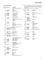
1. SPECIFICATIONS
2. PANEL FACILITIES
3. DISASSEMBLY
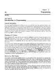
3.1 Panel.
3.2 D.D. Motor
3.3 Tonearm
3.4 CdS Detectorand Lamp
4. PARTS LOCATIONS
5. BLOCK DIAGRAM
5.1 TonearmControl Stage .
5.2 End Detector Stage.
5.3 Arm ElevationControl Stage
5.4 SizeSelectorStage .
5.5 RepeatControl Stage
5.6 LoweringPositionDetector,Plunger
Control Stageand DescentSignal
Generator
5.7 DisplayStageand PlungerDriver .
5.8 ManualDriveStage
5.9 TrackingSensorStageand
Tonearm Driver Stage
5.10 D.D. Motor Control Stageand
D.D. Motor Stop Control
6 . C I R C U I TD E S C R I P T I O N S
6.1 FullAuto Logic .
6.2 TonearmDrive .
3
4
6
7
7
I
I
11
13
13
13
13
13
13
13
14
14
14
15
21
7. ADJUSTMENTS
7.1 D.D. Motor OperatingPoint
Adjustment
7.2 Auto Lead-inTiming Adjustment
7.3 End SensorSensitivityAdjustment
7.4 End Timer Adjustment
7.5 TrackingSensorZero Point
Adjustment
7.6 TrackingSensorGainAdjustment . . . . .
7.7 Lead-inand ReturnSpeedAdjustment . . .
8. TIMING CHART
9. TROUBLESHOOTING
9 . 1 C i r c u i tB l o c k .
9.2 MechanismBlock .
1 0 . E X P L O D E DV I E W S
10.1 Exterior
10.2 Tonearm
10.3 EV Mechanism
10.4 Bottom Plate .
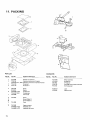
11.PACK|NG....
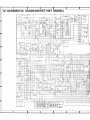
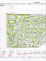
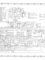
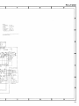
12. SCHEMATTC
D T A G R A M( H E T , H B T m o d e t ) ..
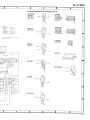
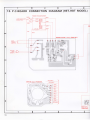
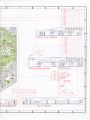
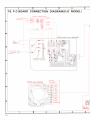
1 3 . P . C .B O A R D C O N N E C T I O ND I A G R A M
( H E T ,H B T m o d e l )
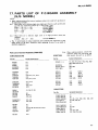
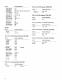
1 4 . P A R T S L I S T O F P . C .B O A R D A S S E M B L Y
(HET,HBT model)
1 5 . S C H E M A T I CD I A G R A M ( S / c m o d e l )
1 6 . P . C . B O A R D C O N N E C T I O ND I A G R A M
(S/G model)
1 7 . P A R T S L I S T O F P . C .B O A R D A S S E M B L Y
(S/G model)
25
25
25
25
t
26
26
26
27
3: l
45
48
50
51
54
55
58
61
63
a
e
\
PL-L1 clclcl
Fr
)
ftr,
t
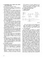
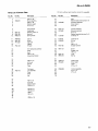
1. SPECIFICATIONS
Motor and Turntable
Semiconductors
DriveSystem
.. Direct-drive
Motor.
....OuartzPLLHalm
l otor
TurntablePlatter . . 31Ommdiam. aluminumalloy die-cast
InertialMass . . . . 330kg-cm2(includingplattermat mass)
Speeds
. 33-1/3 and 45rpm
*0.013%(WRMS)
Wow and Flutter
Lessthan
o.o25Yo(WRMS)
0 . 0 3 5 %( D t N )
Valuesmarked with an "*" designatethe wow and flutter j
for motor, and do not include the cartridgeor tonearmI
load.
S i g n a l - t o - N o iR
s ea t i o
M o r et h a n 7 8 d B ( D l N - B )
(with Pioneercartridgemodel PC-600)
fCs...
Transistors
Diodes
H a l El l e m e n t .s. .
LED..
PhotoTransistors.
cds..
22
17
16
....3
14
.....
5
1
Miscellaneous
PowerRequirements
HET,HBT models
. . . AC22O/24OV- (switchable)
50,60H2
- (switchable)
S/G model
. . ACl 10/12O/22O/24OY
50,60H2
P
o
w
e
r
C
o
n
s
u
m
p
t
i
o
n
..35W
RotationalCharacteristics
Dimensions
4 9 4 ( W )x 1 5 4 ( H )x 4 5 6 ( D ) m m
Build-upTime .
. Within 90o rotationat 33-1/3rpm
19-7116(W
x 6) - 1 1 1 6 ( H l 1
x7-15/16(D
i n) .
SpeedDeviation . . .
Lessthan O.OO2TI
Weight
12kg/261bfbz
Speedvs. Load Characteristics. . . . Stableup to 220 grams
Accessories
drag load
EP Adapter
1
. . Lessthan 0.00008o/o/h
SpeedDrift
at 33-1/3rpm
Screwdriver
1
Lessthan 0.00003%/degree
temp. changeat 33-1/3rpm
Overhanggauge.
......1
Tonearm
Level .
1
Type .
.......
.. LinearMotorDirect-drive C l e a n i n g c l o t h .
1
Cartridgemountingparts(HET, HBT modelsonly)
Static-balance
type, Linear-tracking
arm
Cartridgemountingscrews
EffectiveArmLength
...6
....190mm
Cartridgemountingnuts
Overhang
...2
....0mm
Cartridgemountingwashers
.......
UsableCartridgeWeight
. . .49 (min.) to 249 (max,)
2
CartridgePC-600(S/G model onty) .
Arm HeightAdjust Range
. . t3mm
1
Operatinginstructions(Frenchand German
Headshell
weight
10.5g
furnishedon modelsfor HET)
1
Subfunctions
Auto lead-in
Auto-return
Auto cut
Ouick repeat
Ouick play
Ouick stop
Stylus pressure d i rect-readoutcounterweight
Arm heightadjustingdevice
Cueingdevice
Freestop hinges
NOTE:
Specif ications and design subject to
without natice, due to improvements.
possibte modif ication
T
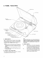
2 . P A N E L F A C I L I TE
IS
I
@ Dust cove.
@ Arm rest
a
/ t \
v
t
Power switch
@ ouartz lock
indicator
@ Arm ctamp
@ seeeo
@ otsc slZE switch
A
-
19, I onearm
(!) R EPEATswitch
( O A R M E L E V A T I O Ns w i
r)-
@ srnnr/sroP switch
V
@ Remote operation knob
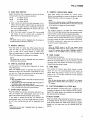
POWER
SWTTCH
e
Used to switch on and off the power to the turntable.
(ON).
P o w e r i s s u p p l i e dw h e n t h e s w i t c h i s d e p r e s s e d
T h e S P E E Ds w i t c hi n d i c a t o r( 3 3 ) c o m e so n . T h e p o w e ri s
switchedoff when the POWERswitch is released.
NOTES:
r
.
.
The platter doos not rotate when tho tonearm is positioned at
the far right oven if the sl,lritch is depressed and the powgr
supplied.
With each push, this switch alternates between the ON and
OFF positions.
Keep the POWER switch at the OFF position when you are
not using the turntable.
@ euARTz LocK rNDrcAToR
T h i s i n d i c a t o ri l l u m i n a t e sw h e n t h e p l a t t e r i s r e v o l v i n g
at the specified rateof 33-1/3 or 45 rpm.
\.
NOTE:
lf the platter speed varies, such as when the speed s:witch is
changed from one position to another or when you press momantarily on the platter, ths indicatorwill go off. As the platter
ro/olution returns to the specified sped, the indicator will illuminate again.
swrrcH
@ sPEED
33 . . . . . . Set the switch to this positionwhen playing
a 33-1/3 rpm recordsuch as an LP. Whenit
is depressed
t h, e 3 3 i n d i c a t o rl i g h t su p , a n d
the platterrotatesat a speedof 33-1/3rpm.
45 . . . . . . Set the switch to this positionwhen playing
a 4 5 r p m r e c o r d l i k e a n E P . W h e ni t i s d e p r e s s e dt,h e 4 5 i n d i c a t o rl i g h t su p , a n d t h e
platter rotatesat a speedof 45 rpm.
a
PL-L1
t
@ DrscsrzEswrrcH
Selectsthe switch that corresponds
to the sizeof the record you want to hearfor auto play operation.
12"30 . . . For 30cm records
10"25 . . . For 25cm records
7"17 . . . ForlTcmrecords
o Usedto selectthe recordsizewhen depressed.
For instance,when the 30cm indicatorlights up, depressthe
switch for the 25cm position,and depressit againfor
the 17cm position. Depressing
the switch once more
setsit to the 30cm position.
o When the power switch is turnedON, the turntable
will always be set for records with a diameter of
3 0 c m a n dt h e c o r r e s p o n d i nl igg h tw i l l c o m eo n .
NOTE:
This sruitch will not work if depressed when the tonearm is
m o v i n g ( a u t o l e a d - i n ,a u t o - r e t u r n , a u t o c u t ) .
@ REPEAT
swtrcH
Pressthis switch for repeat play. When pressedthe indic a t o r w i l l l i g h t u p , a n d t h e r e c o r dw i l l b e p l a y e da g a i n
(refer to page 12 for further details on repeat play).
Pressthis switch againto releaseit. The indicatorwill go
off and the repeatplay function will be released.
NOTE:
n
This slitch will not work if depressed wh6n the ton€arm is
moving (auto-return, auto cut).
@ enru ELEVATIoN
swtrcH
n'
t,
Use this switch to interrupt play temporarily or to perform manuap
l lay.
When the DOWN position is depressedthe tonearmwill
descendand when the UP position is depressed
the tonearm will rise.Thesetwo operationswill be performedalternatelyeverytime the switch is pressed.
NOTES:
r
r
o
When th€ POWER switch is set to ON, the tonearm will start
in the UP position.
This switch will not work if depressed when th€ tonearm is
moving (auto lead-in, auto-return. auto cutl.
When the switch is at UP, tho auto-return cancelling mechanisrn is actuated and so there will be no auto-roturn.
O sranr/sropswtrcH
Pressthis switchfor auto play. The platterwill startto rotate, the tonearm will automaticallymove over to the
edgeof the recordand play will begin(auto lead-in).
lf this switch is pressedduring play, the tonearm will
automaticallyreturn to the arm clamp position,the platter will stop rotating and play will be suspended(auto
cut).
I
NOTE:
This saritch will not work if depressed when the tonearm is
moving (auto lead-in).
Clclc'
@ REM oTEopERATtoNKNoB
Used when moving the tonearm by remote control.
Rotatecounterclockwise
to movethe tonearmto the left.
Rotateclockwiseto movethe tonearmto the right.
NOTE:
Whon the arm elevation switch is at DOWN or auto lead-in, auto
cut and auto-return, the tonearm does not move even when the
remote operation is releasedand th6 knob rotated.
@ ToNEARM
The tonearm function is to apply the correct tracking
f o r c e t o t h e c a r t r i d g em
. a i n t b i nt h i s v a l u ep r e c i s e lay n d a l low the stylusto tracethe recordgroovesaccurately.
The tonearmcan be operatedmanuallywith your handor
remotelywith the remoteoperationknob. lt is coupledto
the motor switch and when it movesacrossto the record,
the platter rotatesand it stops when the tonearm is ret u r n e dt o t h e a r m c l a m pp o s i t i o n .
NOTE:
When the POWER switch is at OFF, the ton€arm cannot
be moved by either manual or remote operation. lf it is forced
at tho OFF position, this may result in damage so always remember to set the POWER switch to ON when moving it.
@ ARM cLAMp
Usedto securethe tonearm.
To securethe tonearm,move it to the right and then push
down on the clamp.When you do not intend to usethe
turntable,securethe tonearm in this way. The tonearmis
released
when the clamp is raised.
@ anru REsr
T h i s s e c u r e st h e t o n e a r mp i p e . W h e n p l a y i n ga r e c o r d ,
rotate the arm rest counterclockwiseand releasethe
c l a m p .W h e n n o t p l a y i n ga r e c o r d ,s e t t h e a r m e l e v a t i o n
switch to UP ( ! ) and then rotate the arm restclockwise
and securethe pipe.
NOTE:
When the arm elevation sritch is at DOWN (l l, ttre tonearm
pipe cannot be secured. Make sure this sl,tritchis set to tho UP
( ! l position.
@ p I R I I E R / R U B B E R p L A T T E RM A T
Whenthe tonearm is movedand power is suppliedto the
turntable,the platter will start rotatingat the set rotation
speed.The rubber platter mat stabilizesthe recordsand
alsoabsorbsexternalvibration,
@ ousr covER
Keep this closedunlessoperatingthe controlsor tonearm,
or changingrecords.This servesto keepdust off of the records during record play. When fully openedand pulled
straight up, this dust cover can be removedfrom the
cabinet.
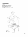
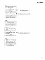
3. DISASSEMBLY
3.1 PANEL
1. Remove the 4 insulator mounting screws.
2. Remove the top cover.
3. Shift the tonearm acrossto the center4. Lift the panel up, and disconnect the B con_
nectors from the printed circuit board below.
Top cover
I
)
a
F i s .3 - 1
Ei
FL-LI
t
Oclcl
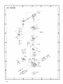
3.2 D.D MOTOR
1. Remove the 3 D.D motor securing screws.
2. Disconnectthe D.D motor connector.
)
l"
a
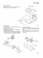
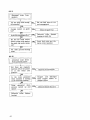
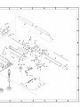
3.3 TONEARM
1. Remove the plate pressing against the tonearm output cable.
2. Remove the coil & rail ass'y.
3. Disconnect the ground lead connected to
the front rail from P.C.B.
4. Remove the E-type washers and screw holding
the gear and rail of the elevation mechanism.
The front rail may then be removed by pulling
Fis.3-2
out towards the right.
5. The other rail may also be removed by pulling out to the right after loosening the securing
screw.
6. The tonearm may be removed once both rails
have been pulled across to the right by at
least 15cm.
E
C o i l & R a i la s s ' y
E-type
washer
!t
G r o u n dl e a d
F i g .3 - 3
Fig.3-4
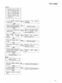
3.4 CdS DETECTOR AND LAMP
1. After removing the tonearm, remove the CdS
detector and lamp in the way indicated in
Fig. 3-5.
2. Remove the shutter before removing the spacer
securingthe CdS detector.
)
I
Shutter
\
@
F i g .3 - 5
a
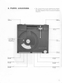
4. PARTS LOCATIONS
o The l\ morh found otr some component parts itldicates
Ihe importance of the sately lactor of the parl. Therefore, @hen replacing, be sure Io use parts of id.enlical
designation.
Tonearm assembly
PPD€01
t
PNR.I26
ri
Dialunit
PXT.391
P u s hb u t t o n u n i r A
PAD-058
Pushbutton unit C
PAD{60
al
Pushbutton unit B
PAD-061
PL-LI
Clclc'
tcotes
lhere
'ntlcal
BtER
rw-339
E V m e c h a n i s ma s s e m b l y
(Coil assembly)
PXB{ 18
nel
\tR.l26
D.D. motor
PX B-061
Controlassembly
PWM{32
ialunit
xT-391
PL-L1
oclcl
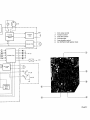
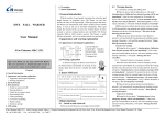
5 . B L O C K D I A G RA M
-l
I
33
45
QUARTZ
I
I
D.D. motor control
Rest sensor
Lead in
|If End signal
Display driver
End sensor
REP
sw
Lowering
1q
1 7 7
I
L-_
____l
I
30 cm
1 1
position
control
rooo
?
I, l r -$-€
Cds
I
J i rl f;
Tracking
sensor, power
supPlY.
I
I
I
Tonearm
drive
l
l
uoll
<
'
I
I
I
I
Manual drive
i €
1
2
3
4
5
6
D.D. motor control
Tonearmcontrol
Arm drivecontrol
Full auto logic
Arm elevationcontrol
E V , R E P E A T,S IZE sel ectori n put
Photo5-1
BLOCKDIAGRAM OPERATIONS
5.1 TONEARM CONTROL STAGE
a. Lead-in FF and Return FF
Lead-in FF . . . . This FF is set by pressingthe
S/S (START/STOP) switch
when the tonearm is on the
arm rest, and is reset by a
descend signal, or when the
power switch is turned on.
Return FF . . . . This FF is set by pressingthe
S/S switch when the tonearm
is not on the arm rest, and
also by the end detector. It
is reset when the power is
turned on, or by the descend
signal, or when the tonearm
returns to the arm rest.
b. When either of the above 2 FFs has been ser, an
"AUTO
on" signal is generated (as well as
AUTO on), resulting in the arm elevator being
set to the UP position, and inhibition of manual
drive.
I
5.2 END DETECTOR STAGE
The end sensor input signal is rectified and then
applied to the detector stage consisting of a differential circuit, integration circuit, and a monostable multivibrator.
When the detector stage detects the arrival of 2
consecutive input signals within the fixed time
constant period, an output signal is generated.
This output, however, is inhibited by the EV Up
signal when the arm elevator is in the Up position.
OUTPUI
E Vu p s q n a
Fig. 5_1
5.3 ARM ELEVATION CONTROL STAGE
This stage consists of a J-K-type FF with a reset
(clear) input and preset input.
The arm elevator is raised (Up position) as a
result of the initial resetting, or by the AUTO
operation signal from the tonearm control stage.
The eleyator descend again (DOWN position)
when the FF is preset by the descend signal.
Furthermore, whenever the EV switch is pressed,
Q and Q are generated alternately, resulting in the
arm elevator being raised and lowered correspondingly.
The FF output is applied to a logical ,,and"
circuit with the outputs from the elevator Up and
DOWN switches,the resultant output being applied
to the EV motor drive stage.
s.iA SIZE SELECTORSTAGE
This stage consists of a J-K FF 2-stage ring
counter and the QUQ2 logical ,,and,' gate. As a
result of the initial resetting, Ql = Q2 = L for automatic switching of the size selector to the B0cm
position. Every time the size selector switch is
pressed after that, the selector is switched from
the 30 to 25 and 17 positions in turn, and then
back to 30 again. Note, however, that switching
is inhibited when AUTO operation signals are
received from the tonearm control stage (i.e.
during lead-in, return, and repeat operations).
5.5
R E P E A TC O N T R O L S T A G E
Consisting of a T-type FF, e and Q are inverted
by Repeat switch operation. Note that the FF is
also turned off by the initial reset, and that there
is no inversion while the tonearm control stage
return FF remains set (i.e. during return and
repeat operations). Furthermore. the FF is also
turned off as a result of auto-cut operation during
repeat mode.
5.8
By
motol
senso
f,onea
opera
is DC
return
5.9
Thr
CdS r
voltag
ment.
the d
to pa
the to
EITOT
senso
./
7V
5.6
LOWERING
POSITION DETECTOR,
PLUNGER CONTROL STAGE, AND
D E S C E N DS I G N A L G E N E R A T O R
When the tonearm shutter passesbetween the
sensors corresponding to the designated record
size (sensors being mounted in positions corresponding to each record size), a lowering position
detector output signal is generated. This signal is
then applied to the plunger control stage (a monstable multivibrator), resulting in a fixed time
constant pulse signal being generated to activate
the plunger (during lead-in and repeat modes).
The down stroke of the pulse signal is differentiated and a descend position signal generated. Each
of the tonearm control stageFFs is also cleared.
5.7 DISPLAYSTAGE AND PLUNGER
DRIVER
This stage is responsible for the LED display
of elevator position, repeat mode, and selected
record size, in addition to plunger drive.
\
PL-L1
5.8 MANUAL DRIVE STAGE
By amplifying the input to the power generator
motor mounted in the locate stage, the tracking
sensor stage balance is upset, permitting the
tonearm to be moved back and forth.
Such
operation is inhibited, however, when the elevator
is DOWN during auto operation modes (lead-in,
retum, and repeat).
5.9
T R A C K I N G S E N S O RS T A G E A N D
TONEARM DRIVER STAGE
The tracking sensor stage (consisting of lamp,
CdS element, and shutter) generates * and voltage differences in response to tonearm movement. These output signals are then applied to
the driver stage where they are amplified, and
to pass a current through the drive coil to drive
the tonearm in such a way as to eliminate tracking
elror (i.e. to avoid the generation of tracking
sensoroutputs).
000
5.10 D.D. MOTOR CONTROL STAGE AND
D.D. MOTOR STOP CONTROL
The phono motor stop control stage stops the
motor when the rest sensor detects the presence
of the tonearm back on the arm rest. As long as
the tonearm remains off the arm rest, the motor
will continue to rotate. The phono motor control
stage employs 3 specially designed ICs - PA2005,
PA2OA4, and PD1003. These control stagesalso
include the speed selector, speed indicator, and
qtartz lock indicator circuits.
End detector
Loweringpositioi
detector
Restsensor
Fis.5-2
PL-L1
c,Clc'
€i. C I R C U I T D E S C R I P T I O N S
6.1 FULL AUTO LOGIC
-rt
O.7nS
g
STAFTJULSE
fL
*es-t
Lolr
LEAD IN.FETURN
REPEAT
--t__f-
STOP
PULSE
o30 |
r TPS60S0
ARM
REST
SENSOF
R E T U R NF . F .
c38
t/5o
r3
/lazt
END
VR4
6 8 0 I ( B ) D E T E C T O FA D J
oN ARMI
/
l'u
R E S T I o U To F I
AFM RESTJARM
REST
OUT OF ARM REST
I
OF ARM REST-,
aRv nEStl
ON ARM REST
ON
OUT
orr *xot.tltl
-t !
ts
8V
t.S/3S t5k
R60 took
I r
lK.liJ_-r\_
R59
Q3O5L-t TPS6050
END
.
TP5
R66
560k
SENSOF
io
,urtt'
rk
c3s +i"9
'
,, o.ol
VR9
3.3k(8)
END SENSOF ADJ
o.gv I
fy--j l-r
'l+
oruo
O.lnS
8V
R54
rok
c27
RrOl3.3k
ocizz \ y-,
c?a
t/5o
\
I
l
#
e.zrs
fr__..iFuu
o.6v
I
8V
A
I
o.o I
rok
c45
LOWERING
AND FESET
o.o?7
c46
t/50
16r-owEntruc
16
-
a._fl-L
.o jaslrziro
BV
|
c m i c mc m i c m
{nss
q55 1.51 | ssr
:"t
S I GN A L
TII\,4INGADJ
VR3
680k(B)
8V
1.5!Ols
R5l
IM
R52
R65
tok
3:"1 r's
?
fi
:J---r_
-lt7
o.o2'
ic3?
t/50
REPEAT
REPEAT
ON
(L)
r L 0 w E R r N GS t c N A L
I CONTR0L
F.F
LEAD
BEPEAT
STOP
IN (H)
1 clclcl
LEAD IN
ra)
tI
REPEATST0P
@
T O A F M D R I V ES E C T I O N
o
MANUAL OPERATION
PROHIBIT SIGNAL
+H
6)
TO D.D.MOTOR
STOP SECTION
-3ov,-4ooma,3oomw
r;\
\9
y' tzoN 24o
Y
2 S4 5 6 2
or
x?
2 SA 5 6 2 T M - Y
c47
to/t6
UP SW
PXM-069
NC
25c735 -Yo r x
2 5 C 1 9 5 9- Y
\
3 O V , 4 OmOA , 3 Om
Ow
tzo-zAo
? ( 9
l .
ONSW
swt
swz
NO
NC
NO
I
I
l
r
3OV,4OOmA
5OOmW
l?Q* 24O
1
l
L - - -
_ _ _ _ _ J
8V
II
swl
o.o I
LOWEF ING
AND FESET
16
:"t
3.t"t, r 's
R37 t.2k
15
6mA
R39 r.2k
sw2
I
I
REP
.t€3
loweRtnc
srcNAL
6mA
l(l
x?
5
.^
r+ -tga
,u
*4
tto
I
I
0209
DN
,(6
ra
6mA
R46 r.2k
R47 t.zl
?5
rr -9i1A
t k
0304
r -- --]
l T c mS E N S O R
30
1
D?
Q303
lsr885
<L
M A X8 m A
g1_-_/ to 1 coNTROr
1 6 . 0 5n A
t
S O L EN OI D
PXP-OO3
6 . 0 5m a
fi
'_r-L_
J L . o w E R l N cs r c N A L
rPS60so
D3O2-3Oa T L R I 2 1
MAx.25Oma ol_zeRt ,e
I
1 . 5+ O . ls
I rc bl
8V
UP
t7
.n5
Q 3 0 2- 3 0 a
R38 r.2k
+
i
,o.r1?
D3O3
2 5 c mS E N S O B
8V
M A X8 m A
| 6.O5mA
t
M A x8 m A
Q3O2
+4.
LOWERING POSITION SIGNA.
t k
tk
0302
3 0 c nS E N S O R
PL-L1 clc'cl
*
x
*
*
Number in parenthesis are the IC pin numbers.
LdenotesLlevel.
HdenotesHlevelEV denotes arm elevator, UP denotes that arm
elevator is in UP position, while DN that
elevator is in the DOWN position.
The Full Auto Logic section is made up of the
following 5 main stages.
(1) Tonearm control stage
(2) End detector stage
(3) Elevation control stage
(4) Record size selector stage
(5) Repeat control stage
6 . 1 . 1 T O N E A R M C O N T R O LS T A G E
1. When the power switch is turned on . . . .
. . . . the lead-in FF and retum FF are reset
by the initial reset signal (passed from
C29lF-55 to IC16,-+ICI7,->IC9, and IC10).
. . . . the phono motor will remain stationary
if the tonearm is on the arm rest, but
commence to rotate if it has alreadv been
moved away.
2. When the START/STOP switch is then pressed
with the tonearm on the arm rest,
* Pin (8) of IC8 is switched to L level.
* Pin (10) of IC8 is switched to H level, and this
appears at pin (3) of IC10, resulting in the
lead-in FF being set (and pin (10) of IC10 also
being switched to H level).
* Once pin (10) of IC10 is switched to H level,
pin (3) of IC8 is switched to L level, resulting
in pin (8) of IC1L being likewise switched to
L level, thereby inhibiting manual drive (locate
operation).
Pin (13) of IC14 is also switched to L level,
resulting in pin (12) of IC12 being switched to
H level, and the elevator being consequently
raised to the UP position.
* Pin ( ) of IC11 is switched to H level, resulting in the inhibition of any further START/
STOP switch inputs after a delay of about lms
(in order to prevent the return FF from being
set when the tonearm leavesthe arm rest). At
the same time, pin (12) of IC18 is switched to
H level to inhibit switching of the size selector.
Hence, the relevant FFs are set, the arm
elevator raised, and record size selector switching inhibited.
Pin (11-) of IC10 is switched to L, and this is
transferred to pin (6) of ICS. Once the elevator
is properly in the UP position, the UP detector
switch is switched to the NO position, resulting
in pin (5) of IC8 being switched to L level, and
pin (4) of IC8 switched to H level.
This IC8 pin (4) H level signal then turns Q7 on,
resulting in a current being passedfrom VR8 to
VRb and R99 via R93. If the potential at TP8
drops below the potential at TP10, the difference is amplified and a current passed
through the coil to subsequently drive the
czrlrier.
The carrier is thus shifted across towards
the record. (Assume size selector set to 30cm).
When the carrier reachesa position about 20mm
in front of the 30cm position, the carrier shutter
will block the light of the 30cm sensor.
Pin (13) of IC9 is thereby switched to L level,
and pin (10) of IC9 switched to H level. This
serves as a trigger for the monostable multivibrator incorporated in IC13, resulting in the
generation of an H level signal of r = 2.2 sec.
This is applied to TP3 and pin (9) of lCL2,
presetting the EV FF for lowering of the tonearm.
The TPB H level signal is used to drive IC7, and
in turn attracts the plunger and raise the index
plate.
The carrier continues to move further, coming to a stop when the swing pin strikes the
index plate.
TP3 is switched back to L level 2.2 seconds
later, the signal being differentiated by C34
and R44 to provide the tonearm descend signal
which is passed via IC1-7, IC9 and IC10 to
clear the FFs and stop the carrier drive current.
The elevator UP, locate inhibition, and size
selector switching inhibition are dlso cancelled
at the sametime.
As a further result of TPB being switched to L
level, the charge held by C35 is dischargedvia
R43 and the IC7 base resistance. During this
discharge period (0.3 to 0.5 sec.) the plunger
is maintained in the attracted position, but is
forced back (by a spring) once the discharge
has been eompleted. The elevator is thereby
retumed to DOWN position for start of play.
l
3. START/STOP switch pressed when tonearm
is not on the arm rest
x Pin (8) of IC8 is switched to L level.
* The IC8 pin (10) change to H level results in
pin (4) of IC10 being changed to L level for the
retum FF to be set.
* This then results in the elevator being raised,
and inhibition of size selector switching, S/S
switch input after a delay of 1ms, and locate.
* The L level signal on pin (9) of IC9 is transferred to pins (5) and (6) of 1C72, thereby inhibiting inversion of the repeat FF. Furthermore,
the IC10 pin (4) L level change is transferred to
pin (4) of IC12 via pin (8) of IC14 to clear
the repeat FF. The purpose of the 1ms delay
circuit referred to above is to permit sufficient
time for the generation of the time pulse employed in clearing this FF.
* In a similar fashion to the lead-in operation,
the L level signal appearing at pin (9) of IC9
once the elevator has been completely raised,
is converted into an H signal at pin (11) of IC8,
resulting in Q8 being turned on. In this case,
however, the TP10 potential drops below the
TP8 potential, resulting in the carrier being
retumed towards the arm rest.
x When the shutter cuts across the sensor light
beam during the retum motion, pin (10) of IC9
is switched to H level, but since the repeat mode
has been switched off, pin (1) of IC13 will be
at H level, thereby preventing operation of the
monostable multivator.
t Once the carrier reaches the arm rest position,
the rest sensor transfers and L level signal to
pin (3) of IC16, resulting in pin (11) of IC11
being switched to L level to stop the phono
motor.
+ When pin (11) of IC11 is switched to L level,
the charge stored on C43 is discharged via R71,
the return FF being cleared after the potential
on pin (1) of IC9 is reduced to 1/2Vcc (delay
circuit). During this period, the cauier remains
pressedagainst the arm rest.
4. End detector operation
* When the repeat mode is off, pin (3) of IC9 is
switched to L level by the end detector, and the
retum FF is consequently set. Subsequent
steps are the same as during normal return
mode.
* When the repeat mode is on, the retum FF is
again set in the same way for normal return
operation.
However, when the shutter cuts
across the size sensor, the plunger is activated
(TP3 switched to H level), followed by the
generation of the descend signal in the same
way as during lead-in. The elevator is thus
lowered for recommencement of play.
.Jl
6 . 1 . 2 E N D D E T E C T O RS T A G E
1. Detector Principle
* Shutter structure
hhnin
"n
ff""
I
.IE;
i
Fis.6-1-1
-r\4'
#
F i g .6 - 1 - 2
[1
-l-LlE
Fis.6-1-3
Fis. 6-2
That is, the detector circuit (outlined in the
above block diagram) has been designed to
detect the presence of 2 rising edges of the
Schmitt circuit output within 1.0610.1 seconds
2, Circuit Description
The end sensor is mounted at a position
R49mm from the spindle. When the left edge of
the shutter slits reaches that position, the stylus
tip will be at the R62.5mm position. That is,
there is 20mm between the 62.5mm position and
the point of entry into the detection range. Once
the detection range is entered, the sensor commences to generate output signals with a waveform like that shown in Fig. 6-1-2 above. This out
put is applied to the Schmitt trigger clcuit composed of 2 inverters in IC16 where it is rectified
into the square wave as shown in Fig. 6-1-3. This
output is then differentiated by C39/R61 and
applied to pin (5) of IC14, while another portion
of the same output is integrated by R62|C4O
and applied to the monostable multivibrator composed of 2 NOR gates in IC18, resulting in the
generationof a 1.06 1 0.1 secH level signal.(TPb).
Although this signal is applied to pin (6) of IC14,
there is no detection by pin (5) because of the
delay by the integration circuit.
If, however,
the next differential pulse is applied to pin (5) of
IC14 while the H level signal is being generated at
TP5, that pulse will be detected. Apart from this
case, there is no detection because the differential
pulse involves a slight delay before switching TP5
q
FL-L1 clclcl
to H level.
Furthermore, when the elevator FF Q is connected to pin (6) of IC18 to make Q = H (i.e. Up
-position), the monostable multivibrator is inhibit_
ed, thereby inhibiting the detector circuit. Q = H
also when the power switch is tumed on, again inhibiting the multivibrator.
6 . 1 . 3 E L E V A T I O N C O N T R O LS T A G E
x When the power switch is turned on,
an initial
reset sigrral is passed to pin (12) of IC14 from
R551C29, resulting in pin (11) of IC14 and pin
(14) of IC12 being switched to H level (Q = H).
This corresponds to the elevator being in the
UP position, or in other words, Up priority is
given when the power is first turned on.
* Since Q = H, one of the ICZ transistors
will
be turned on to light up the Up indicator lamp.
x Until the elevator reaches the Up position
the
UP detector switch remains in the NC position,
resulting in pins (13) and (I2) of IC1Z being
both switched to L level, and e13 and e16 of
the elevator drive stage being both turned on
to start up the motor.
x Once the elevator is properly in the Up position,
the UP detector switch is switched to the NO
position, resulting in pin (18) of IC1? being
switched to H level, and pin (11) of IC1Z being
switched to L level. Q1B and e16 are both
turned off and the motor stopped.
x If the elevator switch is then pressed,
a falling
edge differential pulse is generated on pins
(1) and (2) of lCL4, and a rising edge clock
pulse on pin (13) of IC12. This results in
Q = H and Q = L for lowering of the elevator
(DN).
* And since = H, the DN indicator lamp
will be
Q
lit up, and the UP indicator turned off.
x The DN detector switch remains in
the NC
position until the elevator is right down. During
this period, pins (9) and (8) of IC1T will be
both at L level, while pin (10) of IC1? will be
at H level. The elevator drive stage e14 and
Q15 will thus be on and the motor rotating.
x If the elevator switch is pressed during
this
condition, Q will switch to L and Q to H (Up)
to reversethe motor.
The above description relates to the opera_
tion of the elevator circuit itself. In addition,
* automatic mode UP (as
described under the
tonearm control stage),and
* DN at the lowering position,
may be controlled via the elevator FF preset
and clear terminals.
6 . 1 . 4 R E C O R DS I Z E S E L E C T O RS T A G E
x When the power is turned on, the initial
reset
signal from P"55lC29 is passed to IC16 to
switch pin (11) to H level, resulting in IClb
being cleared.
* Pin (1) (Q1) and pin (15) (e2) of rClb
are
both switched to L level, this then being transferred to pins (8) and (9) of IC18. pin (10) of
IC18 is thus switched to H level and the BOcm
indicator lamp is lit up.
* If the size selector is then pressed, the falling
' edge differential pulse applied
to pin (18) of
IC18 when pin (12) of this IC was at L level
(i.e. when none of the lead-in, return, or repeat
modes was operative), is instead applied to pin
(11) of IC18 as a rising edge clock pulse, thereby
activating the ring counter in IC1b. As a result,
Q1 = H and Q2 = L. The BOcm indicator lamp
is turned off, and the 2bcm indicator lamp
turned on.
* If the size selector is pressed
again, the 17cm
indicator lamp is turned on. Every time the
selector is pressed, the size is switched in a
cyclic order 30 -->25 -> L7.
6 . 1 . 5 R E P E A TC O N T R O L S T A G E
* When the power is turned on,
the intial reset
signal from R55/C29 is applied to pin (g) of
ICI4, resulting in pin (10) of this IC being
switched to H level, and pin (1) (e) of. lCL2
being switched to L level.
* The repeat indicator lamp will
thus be turned
off(sinceQ=L).
x If the repeat switch is then pressed,
a falling
edge differential pulse will be applied to pins
(5) and (6) of lCL7, and a rising edge clock
pulse generated at pin (4). As long as the
repeat or return modes are not operative at
this time, pin (5) (K) and (6) (J) of IC12 will
both be at H level, resulting in e - H, and Q
= L for the repeat indicator to be
turned on.
At the same time, pin (13) of IC13 is switched
to L level, thereby enabling the monostable multivibrator consisting of 2 gate circuits in IC1B
to operate during repeat.
x If the repeat switch is then pressed
again, the
J = K = H status will be inverted.
In addition to the above repeat control stage,
x The START/STOP switch may be pressed
to
activate return mode. In this case, a falling
edge pulse is generated on pin (4) of IC10,
and then applied to pin (S) of ICL . pin
(10) of IC14 is thus switched to H level, and
the IC12 FF cleared (repeat off), resulting in
Q=LandQ=H.
* When the retum FF is set (during return or
repeat mode), pin (9) of IC9 is switched to L
level, this being transferred to the J and K
terminals of the repeat FF, thereby inhibiting any inversion.
I ,
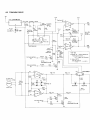
6 . 2 T O N E A R MD R I V E
24V
TP8
tczz !PC78LOB
1 5 . 4- 1 6 8 V
TP9
Tracking "O"
t?v
I o S H O R T: t 5 0 m A
3
EEBr',
IJ;:j;"'
"O"
TPII
Po:lW
7 . 7- 8 . 5 V
Q.o1o/o / oC
rc?t t/2
adj.
R93
t.?k
TH I
R89 68k
Tracking
sensor gain
cq,.t?!',l33Tl
adi.
M A X€ E
22.3V
(otVcc:24
, .c50 0.ol
TH 2
RgB 6Bk
8 V
TOmA
MAX
5.3mA
PEL- 04 I
?4v
Tracking "O"
t?v
5
rczt t/2
Lead in
speed adj.
o'13mA
Full auto section
| @-@
Tracking "9" --within several mV.
Tracking error 4mm ----1.2 - 1'.25V (ref. Fig. 6-4)
R9l
?.
25C945-PorQ
o l3mA
Full auto sectaon
tok (250c)
P C X -O 5 4
Rgz
Gain of 25oC
68+tO+68+tO
+t=2O.O
4.2
tl.Bh
o:
2 5 C l5 8 3 - F r
R80 4.7k
R82 4.7k
5,v 2OO rpm
7mY/ rom l9o/o
ltj
D6
152473
D5
xq
ts 2473
1 5 ? 4 73
PXM- 076
24t!
MAX
2.7mA
took
R79 47r
R 81 4.7k
TC20 t/2
MAX
3.6 mA
MAX
3.6mA
Full auto section
q4
Q4,5
25C945-PorQ
FL-L1
I ceg
to/35
roc
|
|
uAx
3OOmA
( 250 Cl
TP I?
M A X€ E
?2.3V
( o t V c c= ? 4 Y I
--within several mV.
error 4mm --- -,1'.25V (ref. Fig.6-4)
+ t=20.o
2 SC l 5 8 3 - F o r G
1S?473
MAX
2.7mA
t?5A671-Bor C \
\ esclo6l -Borc) x 2 or
t 2 5 A 8 1 6 - O o r Y\ - ^
\ z S c 1 6 ? 6 - o o r Y) ^ '
ClClCl
The tonearm drive stage contains the following 3
major component circuits.
(1) Tlacking sensor circuit
(2) Tonearm drive circuit
(3) Manual operation circuit (locate operation
circuit)
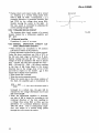
6 . 2 . 1 T R A C K I N G S E N S O RC I R C U I T
An outline of the tracking sensor circuit is
shown in page 21. When the stylus is positioned
exactly at right angles to the carrier, the lamp
Coil Ass'y
beam is directed practically equally onto both
P X B - I I 8
CdS elements, which means that the resistance in
R=73t5rl
(or 25('C)
both elements will also be more or less equal.
These 2 elements form part of a Wheatstone
bridge with R93, R94, and VR8, this latter variable
control being adjusted so that no potential difference is generated across TP8 and TP10 when
the stylus is located at right angles to the carrier.
If the stylus should happen to move to either
left or right, the amount of light striking the CdS
elements will change, resulting in the resistance of
one element being increased, and the resistance in
the other element being decreased. A potential
difference will thus be generated across TP8 and
TP10.
The relation between stylus movement
and the potential difference generated is shown in
grasp form in Fig. 6-4. VR? is used for adjustment
purposes.
i< When the stylus is positioned at right angles
to the carrier, the bridge is balanced, and the
carrier remains stationary.
* If the stylus should tend towards the left of the
ca"rrier, a (+) potential will be generated across
TP8 and TP10: This signal is amplified in the
tonearm drive circuit (sec. 2.2 below), resulting in a coil current to move the carrier to the
Ieft. (During record trace, or when moved to
the left by hand).
* If the stylus should happen to tend towards
the right, a (-) potential will be generated
TPlO@
across TP8 and TP10. After amplification in
vol t
the tonearm drive circuit, the resultant coil
current serves to move the carrier to the right.
(During record trace, or when moved to the
right by hand).
{€ During lead-in Q7 is turned on, and a current
is pumsedfrom R93 to R99 via VR5. A (+)
potential difference is generated between TP8
and TP10 by the voltage drop across R93,
resulting in the carrier being moved to the left.
Speed is controlled by adjusting the current
Fis.6-4
passingthrough VR5.
R
PL-L1 clclcl
* During return and repeat modes, Q8 is turned
on, resulting in a current being passed from
R94 to R98 via VR6. Consequently, a (-)
potential difference is generated between TP8
and TP10 by the voltage drop across R94,
thereby moving the carrier to the right. In
this case, speed is controlled by adjusting the
current passingthrough VR6.
6.2.2 TONEARM DRIVE CIRCUIT
The tonearm drive circuit consists of a current
booster formed by a differential amplifier and
Qe - Q12.
1. Differential amplifier
Consisting of a pair of op amps.
6.2.3 MANUAL OPERATION CIRCUIT (LOCATE OPERATIONCIRCUIT)
x When elevator not completely in UP position
(UP detector switch in NC position).
x During automatic modes (lead-in, return, repeat).
Under the above conditions, pin (10) of IC1l in
the full auto logic stage is switched to H level,
thereby tuming Q4 and Q5 on. The collector
voltage of these 2 transistors will thus be almost
zero. Current will also flow through the D10 R82 - Q4 and Dg - R81 - Q5 routes, resulting
in the base of Q6 being biased in the reverse
direction due to the voltage drop of Vp of D9
and D10 in respect to the emitter. eO is this
tumed off to inhibit locate operation.
* When locate dial is rotated.
* When the motor generatespower.
* When the motor rpm is low (slow rotation of
the dial), the amplifier gain is determined by
R76 + R7? +
1, but once the motor rpm is
R7g
increased to a certain rate, the gain will be
clamped by the voltage determined by D7 and
D8, or D5 and D6.
* When the differential amplifier is activated,
one side of Q6 is turned on according to the
rotational direction of the dial, resulting in
a voltage drop across R93 or R94, and the
generation of a potential difference between
TP8 and TP10. This is subsequently ampli
fied, and results in a current being passed
through the coil to move the carrier.
Coil current
Fis.6-5
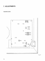
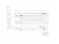
7. ADJUSTMENTS
Adjustmentposition
VRl VR2
vnz@@ vna
vno@)@)vns
Fis.7-1
)
)
)
Preparation
1. Disconnect the panel according to the disassembly nrethod outlined earlier.
2. Use extension leads to connect the panel to the
printed circuit board located in the basesection.
3. Remount the turntable platter (but without
tightening the securing screws).
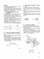
7.1 D.D. MOTOR OPERATING POINT
ADJUSTMENT
1. Connect the TP1 and TP2 terminals to the CH1
and CH2 inputs of a dual-trace oscilloscope.
2. Start the turntable platter turning by shifting
the tonearm over towards the center of the
record from the arm rest position.
3. Observe the waveforms in the oscilloscope, and
adjust the corresponding controls so that the
rising edge of the TP2 output waveform lies
within the TP1 output waveform.
4. VRl is the control to adjust for 4brpm speed,
while VR2 is the control for 33rpm adjustment.
10v
TP1
_,1-l_
TP2
_Fis.7-2
)
7 . 2 A U T O L E A D - I NT I M I N G A D J U S T M E N T
1. Set the record size selector to the 30cm position.
2. Pressthe START/STOP key to start the tonearm
lead-in movement.
3. When the tonearm is about 20mm away from
the outer edge of the record, an output pulse
signal will appear at TP3 (see Fig. 7-3). Adjust
VRB to obtain a time constant of 2.2 - 2.5 sec.
for this pulse signal.
7.3
END SENSOR SENSITIVITY ADJUST.
MENT
1. Connect the oscilloscopeto the TP4 terminal.
2. Set the arm elevator to the UP position, and
shift the tonearm across to near the lead-out
gloove.
3. Hold the tonearm carrier by hand, and move
the tonearm back and forth at a rate of 5 to
1Ocm/sec.
4. During this operation, adjust VR9 so that the
TP4 output saturates at H and L levels at about
'
50% duty.
\
7.5
1.S
a
j
2.S
t
a
a
c
f,
7.6
1.
t"
|\l,l/l/l
JU\/UV
\.
Fis.7-4
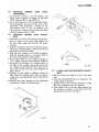
7.4 END TIMER ADJUSTMENT
1. Connect the oscilloscopeto the TP5 terminal.
2. Secure the tonearm to the arm rest. and remove
the turntable platter.
3. Insert a piece of paper (or any other light
shield) into the end sensorstage.
'4. As soon as the piece of paper (or light shield)
is removed, an output signal appears at Tpb.
Adjust the time constant of this output to
1.06 10.1 secby meansof VR4.
p
t
r
2.S
a
a
3.V
s
{,
4.7
1
5.f
t,
ti
n
s
* 1 .I
li
ir
v
*2.
h
li
Fis.7-3
F i g .7 - 5
25
PL-L1 clclcl
7.5
TRACKING SENSOR ZERO POINT
ADJUSTMENT
1. Set the arm elevator to the UP position, and
adjust VR8 to obtain of voltage of less than
t0.1V betweenTPg (-) and TP12 (+).
2. Set the arm elevator to the UP and DOWN positions repeatedly, and also perform each of the
automatic mode operations. Finally set the
arrn elevator back to the UP position, and
check that the voltage across the TP9 and TP12
terminals remains below t0.35V.
7.6
TRACKING SENSOR GAIN ADJUST.
MENT
1. Disconnect the drive coil connector, and insert a
piece of paper (or any other light shield) into
the rest sensor stage and stop the DD motor
rotation.
2. Shift the tonearm across to any desired position
above the turntable platter, and then fix the rail
and roller to secure the carrier.
3. With the arm elevator in the DOWN position,
shift the tonearm across to a position 4mm to
the left of the tonearm center position.
4. Then adjust VR7 so as to obtain a voltage of
7.2 to L.25V acrossthe TPS and TP10 terminals.
5. Next shift the tonearm to a position 4mm to
the right of the tonearm center, and check that
the voltage across TP8 and TP10 varies by no
more than 10.L5V from the value measured in
step 4 above.
*1. Because of the "ghost" tendency caused by
light from the tracking sensor lamp (as shown
in Fig. 7-8), this adjustment must be performed
with care.
*2. Perform the above tracking sensor adjustment
procedures(7.5 and 7.6\ at least twice.
F i g .7 - 6
Fig.7-7
1.2V--
I
I
I
Ghost
Fis.7-8
LEAD-IN AND RETURN SPEED ADJUST.
MENT
1. Set the record size selector to the 17cm position.
2. Press the START/STOP key to commence the
tonearm lead-in operation.
3. Adjust VRb so that the time required to reach
the 17cm position is 5.5 to 6.5 seconds.
4. Then adjust VR6 so that the time required for
the tonearm to retum to rest from the 17cm
position is also 5.5 to 6.5 seconds.
7.7
PL-LI
clclcl
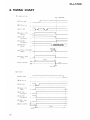
8. TIMING CHART
(1 )
LEAD IN PLAY
(3 ) REPEAT
30cm DISC SIZE
I
(A)
Rest signal
t
L
(A)Rest signat
,
( B ) 30 Srze ind.
L
( B ) 30 size rnd
I
( c) s/s sw
(C)30"' sensor
(lOa1
- 2)
( D ) Lead in F.F.Q
(tcto_to)
L
(E)EV SWI
(up detector)
L
( G)
( H'
(F)
L
R e t e r nF . r . e
(r c s - 6 )
(G)EVswl
(up detector
)
2.2s-2.5s
timims
sisnal
(DN oelector)
( J ) Repeat
L
( ( ) Arm operal on
UP
(2 ) neLrcr
Restsignal
I
L
L
(C)S/S SW
5
L
i
i
( D ) R e t e r nF . r . Q
(|c9-5)
t
r
l
I
(E)EV swl
(up detector)
L
(F)EV SW2
(DN detector)
L
(G)Retern signal
( l c 8 -rr)
(H)Arm
operation
L
UP
DN
l
I
l
l
l
Play
Rejecl
Armup
27
I
\IUIJ-J]
DN
( B ) 30 srze ind.
nd.
, r i Solenotd timrng srgnal
tv J r,^,-^r
( f ) Lead in signal
(A)
L
(H)r.v sw2
:lJ::"$
(J ) Arm operation
]-/]_/l
( E ) f n o d e r e c t o rs r g n a l
( t c I4 - 4 )
L
(rc8-4)
L
I
30cmsensor
( r c g -1 2 )
-
( D ) End sensor
( F) EV SWZ
(DN detector)
L
U
- P
D N -
Play -
,o
srgnal
ze ind.
sens0r
tz)
sens0r
d e t e c t o rs i g n a l
, - 4)
'n F.F.Q
6)
SWI
j e t e c t o)r
lw2
d e t e c t o) r
rt rnd.
L
DN
UP
L
) o r dr m r n g s r g n a l
l-1\
operatlon
I
;
l<-l
N O T E S:
.
t\
-z.cs
UP -
A r m e l e v a t i o nD o W N
S T A R TS T O P S w i t c h
FLip Flop
A r m e l e v a t i o nU P
E l e v a t i o n( T o n e a r m )
DN F . F-
S/SEV -
PL-L1 ctctcl
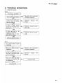
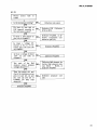
9 . T R O U B L ES H O O T I N G
9 . 1 C I R C U I TB L O C K
9.1.1
No elevator operation
Auto mode in operation ?
Is pin (15) of IC12 inverted every time the elevator
switch is pressed?
Recheck after cornpletion
of present operation
Defective
(rc1,2)
Is there a voltage applied
across the elevation motor
terminals ?
Is there any fault in the
elevator mechanism ?
(Dislodged belt, or poor
gear inter-meshing).
s.1.2
No repeat switch on/off
switching
Return or reoeat mode in
Is pin (1) of IC12 inverted every time the repeat
switch is pressed?
Does the LED lamp light
up when pin (16) of IC7
is connected?
Defective
(rc12)
elevator
FF
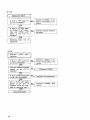
9.1.3
No record
switching
^
size selector
Auto mode in operation?
Is pin (10) of IC18 and
pins (1) and (15) of IC15
switched to H level every
3rd time that the record
size selector switch is
pressed?
Do the corresponding LED
lamps light up when pins
(11), (12) and (13) of IC7
are connected (separate-
lv) ?
Recheck after completion
of present operation.
Defective size selector
stage(IC15 ).
t,t
9.1.4
No 33/45 switching
Is pin (13) of ICb inverted
every time the 33/45
switch is pressed?
Does IC6 function correctly as an inverter ?
Defective LED / Defective
P A2OO4| Defective
PD1003
?
l
PL-LI
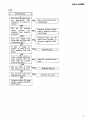
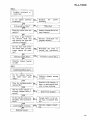
9.1.5
Lead-in failure
START/STOP switch presafter
sed immediately
completion of return operation ?
Wait a few seconds before
pressing again,
Has the UP det€ctor
(elevator
switch
mechanism) been properly
depressed?
Defective elevator mechanism or defective elevator
control stage
Does the voltage drop
across TP9 and TP12 read
a little above 10V ?
Defective drive coil, defective drive transistor, or
incorrect magnetic polarity.
Is there a voltage difference of about 0.7 to
1,4V between TP8 and
TP1O?
Does a voltage difference
exist between TP8 and
TP10 when the tonearm
is moved bv hand ?
Has pin (10) of IC10
been switched to H level ?
Has pin (6) of IC9
switched to H level ?
Defective lead-in FF stage
(IC10), defective START/
STOP switch.
Defective tracking sensor
stage
Clc'cl
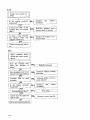
Tt
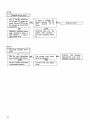
9.1.6
Retum failure
Has the elevator mechanism UP detector switch
been properlY dePressed?
Does the voltage difference between TP9 and
TP12 register a little above
10v ?
---------(No auto cut)
Defective elevator mechanism Defective elevator
control stage
Defective drive coil / Defective drive transistor /
Incorrect magnet polaritY
Is the voltage difference
between TP8 and TP12
about 0.7 to 1.4 ?
q
Is there a voltage difference between TP8 and
TP10 when the tonearm is
moved by hand ?
Has pin (6) of IC9
switched to H level ?
DefectiveIC8, Q8
4,
Has pin (10) of IC10 been
switched to H level ?
Defective retum FF stage
(ICg) or START/STOP
switch
?r,
;{
9.1.7
--------(normal
auto cut)
Does the end sensor oPerate normally (is there
sufficient outPut width
when passing the slit section)?
Out of adjustment, or defective sensor
Does the unistable multivibrator operate normally (including the time
constant) ?
Defective IC18 or surrounding comPonents
q(
PL-L1 clclc'
Repeat failure
Is the repeat FF (IC12)
inverted every time the
repeat switch is pressed?
l
i
h
,,?
Are pins (11), (12) and
(13) of IC9 switched from
H to L level (separately)
when the tonearm passes
the corresponding record
size position when the
repeat switch is on?
Designatedsize
36sm __,pin (12)
Designated size
25qm __,pin (18)
Designated size
17srn .+ pin ( 11)
Is TP3 switched to H
level during the above H
to L level switching?
9.1.9
Tonearm fails to stop at
designated lowering positlon
Are pins (11), (12) and
(13) of IC9 switched from
H to L level when the
tonearm passes the designated lowerins nositions ?
Is TP3 switched to H level
during the above H to L
level switching ?
Defective IC13
-
'r'
9.1.10
Tonearm fails to move
Does a voltage difference
(of at least 1V) appear between TP8 and TP10 when
the tonearm is moved back
and forth?
Is there a voltage difference between TPg and
(around 10 to
TP12
1 5 V )?
Defective tracking sensor
stage (defective lamp or
CdS element, or disconnected lead wire).
Defective drive coil / Defective drive transistor /
Incorrect magnetic polari
ty
;d
'I
9.1.11
1
Abnormal tonearm movement
Has the zero adjustment
been properly performed?
Can proper zero adjustment be obtained ?
Defective CdS element,
disconnected lead wire,
dislodged tracking sensor.
?n
Correct carrier inclination
to horizontal position
1F
:"J
tiA
PL-L1 clctcl
9.1.12
^.|.
II
I
Phono
rotate
motor
fails
to
Do pins (1) and (16) of
ICG respond correctly to
the rest sensor output ?
Defective IC6 / Defective
IC16 or IC11
Is there a 10V output on
pin (15) of PA2005 ?
Defective PA2005, or defective component connected to pin (15).
Is there a voltage difference of 0.5 to 1V between pins (16) and (18)
of PA2005 ?
I'l,,rlo
\ I :'ff
Is there a voltage of about
1.5V on pin (19) of
PA2005 ?
Are each of the Hall
element output terminal
voltages about 4V ?
Tum the power off, and
check the resistanceacross
pins (1) and (2), (1) and
(3), and (2) and (3) of
PA2005. Do they read
about 45 ?
Defective Hall element, defective Hall element resistors R101 - R103, or
defective PA2005
7-
a,
9.1.13
lock failure
Is there a 10V output at
pin (15) of PA2005 ?
Defective PA2005, or defective surrounding component
27 .7 8Hz signal
of 10V ampli
0.66ms Pulse
pin (15) of
Defective crystal oscillator
(PD1003)
Is there a
(at 33rpm)
tude and
width at
P D 1 0 0 3?
9.1.14
Is there a 10V output
pin (15) of PA2005?
Defective PA2005, or defective surrounding component
(,,
Does the stipulated voltage
register on pin (10) of
PA2004?
Is there a differential pulse
on pin (13) of PA2005?
Defective C33 component
Does a delta wave signal
appear at pin (14) of
PA2005 when the tumtable is rotated bv hand ?
Defective PA2005, R12'
or C17
?r.
\ {
llf
PL-L1 clclcl
Motor runaway
Is there a 10V output
pin ( 15) of PA2005?
Defective PA2005 or surrounding component
Is there a 55.5H2 square
wave signal on pin (5) of
PA2004 when the motor
speed is held to 33-1/3rpm
by hand ?
Is there an input from the
FG circuit board?
Is there a 55.5H2 square
wave signal on pin (10)
of PA2004 when the motor is held to the same
speed (33-1/3rpm) in the
Defective wiring, or defective speed detector circuit board
Defective PA2004 or defective R3, R4 C6- C8
component
While measuring the voltage between pins (12) (-)
and (14) (+) of PA2004
with the motor stopped bY
hand, let the motor speed
(rpm) increase gradually.
Does the voltage vary
gadually from -0.5 to
+2V ?
Is there a 27 ,7 8Hz signal
(at 33-1/3rpm) on pin
( 1 5 ) o f P D 1 0 0 3?
Is there any abnormality
in the waveforms observed
in the oscilloscope (see acdiagrams)
companying
when measuring the waveforms at each of the Hall
element output terminals
while keeping the motor
speed steady at 33-1/
3mm?
Defective Hall element or
Hall element resistance
DefectivePD1003
PA2OO4
Defective
related component
IHall elementoutput waveforms]
A.
Normal wav.form
C.
3oomVp-p {max.)
Exampl6
Ex.1
Approx.DC 4V
B.
Low outprrt wav€forrn{AC outpuil
Below 30OmVpf
+ff:re
EX.2
of dinort6d
wav€form
(bul normsl output
levol)
7-
4r'
9.2 MECHANISMBLOCK
9.2.1
Sigrrificant dif ference in
left and right direction
speeds when operating
the locate dial
Is the platter
horizontal?
perfectly
Is there any "play" in the
tonearm ass'y or elevator
shaft ?
Defective tonearm ass'Y,
elevator shaft or bearing
lr
Is the tonearm movement
too "free" ?
Does the speed remain
constant during lead-in
and retum?
Do the lead wires below
the carrier base (A) ass'y
scrape against the guide
bar ?
Does the carrier float ?
Rearrange wires to Prevent
any interference
?n
Proceedto section 9.2.2'
Q-s
9.2.2
L.
Does the carrier float
The damper bearing has
big play in it (backward
and forward).
tf^
PL-L1 clclc'
9.2.3
A
?
Irregular movement in
canier base
Is the platter
horizontal?
perfectly
Is the suide bar clean?
Damper bearing silicon has
been forgotten
e?l
r
!l-
Is there a gap between
the elevator shaft unit
and elevator bar when the
elevator is Iowered ?
Elevator mechanism not
properly adjusted
Do the lead wires below
the carrier base (A) ass'y
scrape against the guide
bar ?
Rearrange the wires to
prevent any interference
Does the carrier float ?
el"
Proceedto section 9.2.2.
Defective damper bearing
or roller
9.2.4
Carrier basefails to move
Do the damper bearing
and roller move smoothly?
Defective damper bearing
or roller
Defective CdS element or
lamp, or disconnectedlead
wire, or loose soldering
Does the tracking shutter
operateOK?
YES
Has the carrier clamper or
tonearm clamper been removed ?
ES
Removethe clamper
Do the relevant parts move
smoothly when moved by
hand?
Foreign matter in the carrier base, or jammed lead
wire
Loose magnet mounting
Defective circuit
:--ls l
Defective magnet mounting
-
^l
9.2.5
Carrier base moves too
freely
Is the platter
horizontal?
PerfectlY
"play" in the
Is there any
tonearm ass'y or elevator
shaft ?
Defective tonearm ass'Y,
elevator shaft or bearing
Is there a gap between
the elevator sheet and
tonearm rubber tip?
Readjust the height of the
elevator sheet
9.2.6
When tonearm shifts
across and traces record
groove
(r'
Does the tonearm shift
when the elevator is
raised?
Does gouging occur in the
darnper bearing and roller?
Defective damPer bearing
and roller
lr-r
1",l
Is the euide bar clean?
Carrier base (B) shifts but
fails to trace
Defectivecarrier base(B)
Circuit not properly adjusted.
fr
PL-L1 clclcl
A
9.2.7
?
Howling noise
Has the AC cord been
stretched tight?
Have the safety screws
(tightened during transport) been removed ?
e,p
9.2.8
9.2.9
l$r
Locate
right
dial
does feel
Problem with the actual
locate base?
Check sections9.2.L & 9.2.3.
4ffi)
['l ,f
9.2.10
Difference in stylus tip
height when in rest
position and when on
the record exceeds4mm
Defective elevator bar
Let the cord lie loose
I
I
iI
I
'f
9.2.11
Abnormal
speakers
Set the lead wires in correct arrangement
Are the lead wires arranged correctly?
EJr
Clean the guide bar
Defective roller damPer
bearing or guide bar
Noise like tumbling roller?
Do the PU leads and/or
shield tubing strike against
the guide bar under carrier
(A) ?
YES
Reset lead wires and tubing in correct position
PU cable ground floating
noise
9.2.12
Abnormal noise direct
from tumtable platter
Are there any magnetic
materia.lsbelow the platter
or in the linear arm
portion?
Is the noise generated
when tonearm is moving
to the lowering position ?
generated when
Noise
elevator moved uP and
down?
l
I
noise from
Foreign matter on guide
bar ?
)
Stopper unit dislodged
from stopper rubber or
plunger rubber
Fr
9.2.13
Elevator does not move
Does guide bar A rotate ?
Flash or foreign matter in
the canier base (A) ass'y
elevator bearing.
Clean
out and/or remove flashes
from the bearing.
Does the driver (E) ass'y
motor rotate ?
Clean off any oil on the
rubber belt
Does the elevator start to
move when the large pulley is rotated ?
Gear (F) and worm stuck
together,
or defective
driver (E) ass'y
Does the elevator bar
strike against the stater
base?
9.2.14
A\f
Lowering position not
attained
Is the platter
horizontal ?
$'
perfectly
Do the roller and damper
bearing operate without
gouging?
Are the lead wires in the
correct position?
Return the lead wires to
the correct position
Does the swing plate move
without gouging?
Defective swing plate
Return to section 1.d.
A f?
position
Lowering
properly adjusted
not
PL-L1 Clclcl
9.2.15
Tonearm fails to lower
on to record after stopping at lowering position, or if it does lower
onto the record it continues to trace the same
one groove
Is the platter
horizontal ?
perfectly
Does the lowering position
sensorfunction properly ?
Is there an unusual meta.llic sound?
Stopper unit stopper rubber or plunger rubber
needs readjustment
Does stopper
against
the
spring?
Stopper unit
position
needs readjustment
unit rub
plunger
Does the index plate move
normally when plunger is
tumed on and off?
s.2.16
Return failure
Defectivedriver 1E) ass'y
Is there gouging in the
damper bearing?
PL-L1 oclcl
1
2
3
1 0 . E X P L O D E DV I E W S
10.1 EXTERIOR
A
B
c
D
1
2
3
{ ooo
iz
6
5
4
.ta
A
-, tK
ry"'
B
)
>,
l
@
ilM
I
' @ l
f
__l
51
c
N
4
5
6
t
PL-LI
;
t
PartsList of Exterior
I
Kay No.
Psrt No.
3.
4.
Doscription
Washertacedalutite screw3 x g
1.
PRW-O68
PNR-126
Caution label
Panel
Control case assemblY
S1
5-2
5-3
$4
6.
7.
PAD{58
PAD{59
PAO-O60
PNX-I35
PDE-O65
GL-2PRl
Clc'Cl
Pushburtonunil A
Pushbutton unir E
Pushbufion unir C
ControlcaseA
CS type washer20
Connectorassembly
LED
Washer faced alutite screw 3 x8
The ! marh found on some component parts indicotes
the importonce of the safet! factor of the part. merefore, when replocing, be sure to use parts of identical
designotiotr.
a Parts without port number connot be supplied.
K.y No.
37,
38.
39.
40.
41.
.42.
rj-43.
,14.
P.C, Board
PT3x8
Part No,
PXT-4O3
Dccription
Motor
Washer faced alutite screw 3 x 8
PNW"338
PNW-339
PDGO21
IH ET, HBTI
PDG{04 (S/cl
PECO51
{HET, HBT)
E32{56 {S/Gl
PlareL
PlateR
PSB3X8
AC powercord
Strain relief
Angle
11,
12.
PBA-104
PNX-092
Screw
Lever
PSG{'|7
Washerfaced alutite screw 3 x 8
Pushswitch
13.
14.
15.
16.
1\17.
.l tA.
' ^j l
-i,20.
a
Wash€r feed alutite screw 3 x 6
PECOs2{HET, HBT) Insulator
eSf-Olz {HeT, HBT) Microswitch
DcE mo rs/G)
rs-l
19-2
r
Switch base
21,
1i 22.
PsA3xls
{H€T, HBT)
Plasticscrew3 x 15
(s/G)
PsA3x15
PTT{97 (HET, HBT)pow€rtransformer
PTT_I00(s/cl
PSB4x8
(HET, HBTI Lin€vottasesetector
PSB.Oo2
PSB{O7(S/c)
24-1
24-2
24-3
PAD-06'|
PAD{62
PAO"O63
244
24-5
25,
26,
27.
PNX-'130
28,
It, X.
30.
PDe{71
PwnOSt
(HET, HBT)
PWR-Osg(S/G)
PDE{67
31.
;
,t'l
32.
33.
34,
PNX{94
PECO63
PBH-257
Washerlaced alutite screw 3 x 8
Control caseB asaembly
Pushbutron unit B
Pushbutron unit D
Purh burton unit F
Control caseB
CStype washer20
Washerlaced alutite screw 3 x 8
Connectorassembly
P.C.Board
pT3 x I
power supptyassembty
Connectorassemory
PSA 2.6 x 6
Base
Nylon batt30
Spring
SF4x5
Washerlaced alutite screw 3 x 8
46,
47.
47-1
47-2
47-3
Label
Dust cover assembly
PXA-463
PNB-105
Hingeassembly
plate
DCM4x8
474
49.
49.
50,
51.
pNV{35
pEA{36
pXB-134
PNR-|21
Dust cover
Rubbermat ass€mblv
Screw
Turntableplatterassembly
53.
PNX-lO8
P l v3l x 5
EV gear
55.
56.
PLBOsl
PLB"OsO
Guidebar B
Guide bar A
57.
58.
59.
60.
61.
PLB{67
EV bar
PXT-391
PRW{46
Dial unir
Label
1
'
1O.2 TONEARM
I
^-.S
,
t-u-l
i
$
a-b
l 1 -: 3
I
|
;t
P
-l-r
yzl
l
ll__t
1
,l
-r
h:rF
:
\r
$.n
F\,r
o
Parts List of Tonearm
Key No.
I
2
s
4
S
6.
7,
7-1
7-2
73
7-4
8.
9.
10.
11.
Part No.
Elescription
PXA€04
PPD6O1
Weightassembly
Tgnearm assembly
Headshellassembly
PXB-116
PNR-127
PXT-414
11-1
1 1-2
11-3
12,
13.
14.
15.
16.
17.
18.
1 8 - 1.
18-2.
18-3
184
19.
PN X-1 03
PCX-051
PNX-1O2
PE L-041
Key No.
31'
32'
33.
34'
35.
Partswithout part number cannot be supplied.
Part No.
Description
PBE{17
PXB-121
PNC-145
PLB-046
BaseB
Washer
Bearing
Spacer
Roller
36.
37'
38.
39.
40.
PXB-120
PLB'O47
PBEO17
PXB-120
Bearing
Shaft
Magnet
Washer
Bearing
EV sheetunit
HS 3x5
BaseA
Screw
41 '
42.
43.
4445'
PLB-O59
PXB-121
Shaft holder A
Bearing
PXT-394
PEB-158
Shaft holder B unit
Rubbercap
S e n s o rb o a r d
Spacer
Cds
PM 2.6 x 6
T r a c k i n gs h a t e r
46.
47.
48.
49.
50.
PADO64
EV adjustscrew
PM 2.6 x 5
Terminal
Fw2.6x5x0.5t
PM 2.6 x 6
51.
52.
53.
PBH-255
EV sPring
EV sheetassembly
StoPPer
Spring
Cramper
Cupler base
LamP
S e n s o rb o a r d
PT 2.6 x 8
PT 2.6 x 8
20.
PSA 3x5
21 .
22.
23.
24.
Shutter
25.
PBA-094
Washer faced alutite screw 3 x 6
Plate
Pinunit
Screw
26.
27.
2829.
30.
PDAO13
PBH-254
PBH-29
P EB - 17 1
PLB-060
S h i e l dt u b e
Spring
Sprins
Rubber Pad
Screw
EV shaft
Pfastic washer 4Q x 0.1 3t
FL-L1 c'clo
ilied.
10.3 EV MECHANISM
\'
h
14
-k
q
16
,6{18
o Parts without part number cannot be supplied.
PartsList
Key No.
1.
2.
3.
4.
5.
6.
7.
8
9
1O
Part No.
PBE-018
PBE-014
PNW418
PNW-390
PSFOos
PDE{68
P EB € 9 7
Description
EW3
Washer
Washer
Key No.
Gear F
Plate
11
12
13
14
15
Cam
PT 2x10
Microswitch
Connector assembly
Belt
16.
17
18
19
20
Part N o.
Description
PNW-393
PNW-391
PNW485
PNW-391
Pulley
Collar
Worm gear
Collar
Chassis
PNW-392
P EB - 16 7
PXM-073
PSA 2.6x5
Frame
Motor pulley
Tube
Motor
PL-L1 clclcl
1
2
3
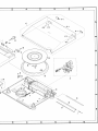
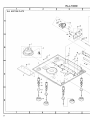
10.4 BOTTOM PLATE
A
B
c
D
1
2
3
tooo
5
4
d
,
*zz
6
A
[\
\ \ni\*
B
\
.11
-\
c
\
g
x
#Lq,
''F-u,
H
@
\
4
D
5
6
PL-LI
l*.(f
PSA4x16
Key No.
Prrt No.
Dorcription
PDE{66
Case
Washertacedalutite screw3 x 8
Connectorassembly
S€nsorboard
PT3xa
Cordclamper
Und€r base
RubbercushionA
SpringC
Springholder
46.
47.
48.
49.
50.
P X B - r1 9
PXP-003
Cramperassembly
Solenoidassembly
PLB{50
Washerfacedalutite screw3 x 6
Guidebar A
'|1. PNW483
12. PBAI05
13. PXT392
14.
15. PNX-I08
CaseC
Screw
Caseunit
PM3x5
EV gear
5't.
52.
PLB.051
PLBO67
54.
55.
PEB-155
assembly
EV mechanism
Ew6
Ew3
PSB4x16
Adjr/stshaftholder
56.
57.
PBA-107
17.
18.
19.
20.
59.
60.
PEB-170
PBH-252
PXB461
PE8,102
PBHI69
PNW375
21.
22.
23.
24.
25.
26.
27.
24,
29.
30.
ffi
D.6cription
PSB4 x '16
Balance
weight
PT3x12
7.
8.
9.
10.
Ar
Psn No.
41.
42.
43.
44.
45.
l.
2.
Fp
a Parts uithout part number cannot be supplied.
PartsList of Bottom Plate
Koy No.
Clc'Cl
33.
34.
36-2
31.
38.
39.
40.
BaseB
Plate
61.
62.
63.
64.
65.
Coil cover
Coil assembly
Plate
Plate
Bar
64.
67.
68
69.
70.
PSB4x12
PXB-1'8t
Guidebar B
EV bar
N 3
PM3x12
Stoppercushion
Screw
Stopperunit
HF3x3
Tube
Spring
PDE-074
PEC{51
Outputcord
Strainrelief
Angle
PT3x12
PWM{32
Control assembly
PT3x'12
PT3x8
PSF3x6
PT3x8
Sensorboard
PSB4xl2
PM2.6x6
PM2.6xg
BaseA
P S B 4 x1 6
F. r,-
53
11 . P A C K I N G
/'
-'-t-----'----a
->-/'
v
zz-tz
--
<?-'
PartsList
Key No.
Part No.
Accessories
Symbol & Doscription
Part No.
Symbol & Description
PEA-036
Rubber mat assembly
PRB.,I56
O p e r a t i n g i n s t r u c t i o n s ( E n g l i s h)
(cerman/French)
PRD'051(HET, HBT) Operatinginstructions
PHA,109
Protector L
PHA-1'IO
Protector R
PXA-8()4
KEX-O02
N93€03
P X B -2
t5
PEC-O12
Screwdriver
EP Adapter
Cartridge mounting part assembly
Overhang gauge
PBA-O79
822426
PHG4O8{HET}
PHG-382{S/c)
PNX-098
Screw
PAW.OOT
PEDO16
C l e a n i n gc l o t h
8
PNXOg7
10
1' |
PHL-006
Spacer
Screw PSB4x12
Screw PSB3x15
Cover
PHC{49
PHN{08 (HET)
PHN{09 (HET)
Upper protector
Headshell
case
Headshell
casecover
I
2
3
12
P a c k i n gc a s e
Packing case
Ksy No.
+r;'
fi,t
q
1
2
3
1 2 . S C H E M A T I C D I A G R A M( H E T , H B TM O D E L )
A
B
Y
|
:-
-
I{=_q*..ft{;|-{fliil#i lll IIl'""""
irytilffitllj
iIrlllllillfitH+
@#t{#i il l l m
I 1 f-^;:$ul6fJl
I i - " ' C ' o - ' l o l l i ' r l l l l - ] L] l l l
l f rf*i"lCl "l "l '
--lar
i
6 * ' l @ l l ' " l l l l llllll
c
l o z o , - z m c . - z p| n ' ? l i i i l l | | | | | | | I
">-------fl-ff
ft1;
, -
r r - '
lli
'-'-'
ll_iiffilfm,lffiffittl
r#Il||l__."1+r#l|nllt
llltrf
l - N ' 7 ' O " " ' ll or 'l
@
L:"-E-rULl
|| ; I- I 110.,9.?
fsrr'lt IfJ-F|1,i--l-;m1 15 | |
:',":;;,lXlA-,,1^l
l+*
|
ffi
| | orP'3
RFofillo"o
|
+
lo2oz-zos 6L-epR!
|
-_=--l/-fJf
| | | | I |
| | | | fi-f:"
i ffil
*
||ffi-
c
-
o
'
|
|
i
|
t
|
|
#
|
|
|i - ' . * . "
r
t
Airs
|
f
lv'rl-l
l c o N r R o L ( B ) A i i , yf - - l - i
Y t - t
; l
t
lF28?rl
|
|
r
rr
I
J
#
r . " . 1
,
l
|
\
l("!l
,
/
*'_-j::_:l_l
|
rr
I
l
||IH; +F'Tffi Ilftr=# lli
|
c
|
.
T
c
.
o
|
'
3
P
|
l
l
|
|
|
|
l
|
|
|
|
l
l
|
l
<"
|
-
lll
t
'
t
t
G+l+
-
llll-..-----------
L-
t-llL'---------------
ru
---------J.-A:-
|
|
r r r
^ s H . t ^ r J - u
I
1
.
It-6H-lol-Y.lllll
|
D
|
|
J^.r
- , , - - - - - - - - - _ - l l |
tltt
t t t G
------@
" 1p a ; _ f f i - a ] r r t : :
llr----=----------:-
i __
llffiffiiffip$1[$,$'+ig,;,-"t
t"*.""_..'+#-J
r
I
| |
.o3or--rc5 rP$o5(
2
I'i@@t1igru1
3
,'
MOTOR Ass'y
towti-6ffia"'v
[-"t;tto"t"
i, @
g-
PwR-o57,
3133;?Y:l%^;*fl
A
sror
POWER
P S F -o r 2
A
ac?zov
2Qv
fi/&42
1. RESISTORS:
lndicated
M:
Ma,
notcd
tolcrance unless othcrwire
in tl.1LW,15%
(F) : t1%. (G) : r2%, (K) :tlO96tolerlnce
k : k{},
2. CAPACITORS:
(!F)/voltage
in cepacity
tndicttcd
without
lndication
(V)
is 50V
voltage
unless othcrwise
except
noted
electrolytic
p : pF
capacitor'
3. VOLTAGE
voltage (V) at no inPut signal
U'DC
otor srRBAro
4. OTHERS:
@
The
CdS Ass'y
| .0,
I Pcx-o5l
L
Dlr Bz-o8l
il
LAMP Ass'y
xlvX- O40
t*t-oot
: Adiusting
A
ponanie
mark
point.
found
of the safety
on
some
factor
component
parts
of the part. There{ore,
indicates
when
the
im'
replacing,
be srre to use parts of identical designation.
This is the basic rhematic
due to improvements
0 9 . l l 2 S C 1 O 6 lo r 2 S C 1 6 2 6
oro,r2 2SA67l or 2SA8l6
06 zSCl583
_I
_I
-i
-<v
--< w
< r
< c
< 0
(
E
diag
indeslgn
PL-L1 clc'c|
7
8
I
Extrsrnal Appearance of Transistors and Il C s
2SA5 6 2 T M
2 S C945
2 S C1 8 1 5
2 S C1 9 5 9
-l-\
r y p e N " + q4 {
,ot No
8
1
6
<\$
rype No-_1\:\
N
>
n,,-=RNi
|
Int\f
r D62504P
TC 4 0 2 7 B P
M
1 5 4157P
/ il\
2SA
2 S C 1626
p 42004
PD 1 0 0 3
,nr Nn
uut/
r
T
T
A
+1 4 0 0 1B P
,,fl( ,(( lrq[
l13l
IBF
a133338'@
E
.ft( q [.
N J M2 9 0 3
pPC4558
2SA
2SC
W
'\''o':,::N^,,
? 3 I T \
. 0 l L A s s ' yP X B -
"rr
ury
d
, o 1
t_r
----
1 0 6 lo r z S C 1 6 2 6
67| or 2SAgl6
PA2005
"t"
583:",-w
P 8 l4 . 7 k
------a^ar--__rr.7t neoc.zrl
h-ftr-t
,
05 I :
o.l
:1.,a"'
"D
2 S C1
rqr-Q'
--1|l
t
lnerlfnerl
l'oo*l froorl
t
l
--T---lt
l
t
t
i2TM t8t
)59
IPCTSMOgH
l
l
r ,,,1ffi^"
,
":;N
",,trTfi
+
r r u
c@to/to
nnn
,'n" nnnnnno
25D 6
8
6
I
F$z-Q"'
.
N
rYPe-"N
*/\*"1
FrOz
2.2r
Rrd3 |
2 2\ |
N+-l-LotNo
)r-
|ilrFr
\rq
gtJtl
rultl
'
T
^ U
v
t ft !
pPCT
J _lI
rlos
N
r Y P e" N L o t N o
D
!M
7
8
I
1 3 . P . C . B O A R DC O N N E C T I O ND I A G R A M( H E T , H B TM O D E L )
POWER TRANSFORMER
col
P O W E RS U P P L YA s s ' v( P W R - 0 5 7 1
s 10 1
P O W ER
SWITCH
^
n
TTT
[_
."'I
,;i,l
I
|t i\l*:*
l--
I
n
*
Il
AC220V
240V
50/60H2
8P"t"o
o
|
I
ma
ez-26
IFE]
tT +l
ll++ll
.:f,*
olol
T 24 i9o!!!,
I
n /')A..
l"{(-\)
I \:7
T@,
EIO
lPc7oxogH
F;l-"
l,. l
l'"1
:*i*
%{--
.*tr'
l-
.? ",-
T,'c"
3$"
".#-
B LK/WHT
A s s ' y( P X 8 - 0 6 1 )
1
5
4
6
7
I
9
lc
il
CdS Ass'y
(xwx-041)
PL-LI clclcl
T4ODEL) C O I L A s s ' y ( P X B - I 1 8 1
CONTROL Ass'y (PWM-0321
ffi
EEEEEEEEr,n,Tn*r"T
a
t
5
J-r.61
fllrf;+ihr...#
ul
w
"* "..""t,t la "t ".-"t
l2rIlE.t
.t
:l o'a Sa
r'.t
\\.
\-
ffi1ffi,:i'uirffiE:=
.'J
-a
1.J
tffi
|
"'?'''
o
Oe
p"'nFJ+..-O
ft
;-+-
lfi:.
Rsb,
? t
I l . - - - - - - € l
r.I
'
=-t
I llt = *.:'. JF-.g. t#1,---_f*=
F1tl1i"l"o"!.'!t"t
Tdr
rt*
rff
r4E
rii!11ffiffi":*ffi(W
[:l4flili
JJ
ln.-:!-- r' .'-.ffi+." :-itil+i.-.r!ilk::+i l
{iIlJi:ihtffi i;[i#, !t'.Nffi,ll
{JI-,,iforu'
l'
rb-ll
l!.ffiIlir"lllrp:*"ffi
tt$.
i fill'Sil]]Hh*f
w#{dl
: =
a
l'-;:: i
1t.lil,,
I
licsrchse"
"F,s=*..
;.
;J.
#**ff
j.l|i#hb[= SF
I
lllffiffis-s'l-g#l
ts lilfry.-1-rii:s:*rtj f-' r
.llHS=][*ffi3;o;BMk=.E
'll,#
ll
,
F'hffiJ-*tlw,rr-4-5,1
/
[?:r;ffi=:-tt
-rTsr-rj
-
F
t
*^E
#ffi/'
trffii;"#;rui
I*l*,)F
lii&*_€q
=trglj.iE
CdS Ass'y
(xwx-0411
LAMP Ass'y
(xwx-040)
PHOTO Tr. Ass'y (XWX-043)
./
BED
-
BRN
14
OR
_ YEL
--
BLK
N01
PNK
o
BLU
H
tl
Ex.
VLT
GRY
WHT
ffi
0ZOr- ?06
GL.2PFI
lt : l l
,N
t-4
'r''\ru
(l)'"
CONTROL(Al Ass'y (XWX-0441
RED
oTl
BRN
80
id
I
YEL
PNK
BLK
it$ it*..,
BLU
*:H*
-
a.!:ll*l{'
i ' d ! 1
\
\
t\._.€-.-ivg5
.N
t a
o a l o
-r
e{'rP
r-lco
? ?
, -,oo'
| 4
+{
I'a
.-
irq
--tN.--{
sl-.:}.
l'rr
a
"""-_-l
_ l l
SEM
WHT
ri
f.
Part
:t'll,l
:=:
a
?
i :
Part I\
RED
O2O7 - 2@
Gr-2PR1
rD,".,.^,,
-f
DRIVER (E) Ass'y
CONTROL(B) Ass'y (XWX-045)
[ - -
+ t
atra
.I .,,rii::"
PT
PA
PA
NJ
JC
TC
M:
TC
TC
TC
TC
TO
pP
ttP(
2S
(25
25(
2SC
25A
il"--l ,, ii-;;il
l--n
I
\ r i
--.
oN
, r
l
s
l
'
2Sr
2SC
N o
(uP)
|
wz
rs1
ts2
VD
A
9*
LED Ass'y (XWX-042)
(t)
-rr
-@
RDi
wz
PL-LI ooo
14. PARTSLtsT gl-.p.c.BoARD ASSEMBLY
(HET,HBTMODEL)
..^_^
NOTE:
I
t
when ordering resistors,first conuert res$tance
uarues into cod.e torm os snoun tn
the follouing eromples.
Ex. I when there ore 2 effectiue digits (any
digit aport from 0), "'"
such as 860 ohm
ond 4zh ohm (toterance is shown by J = izo,
ira i : ibij'
56oa56 x l0t__s6t
RDylpS 6@A J
47he47
0.5a-0Rs
RN2H @@E K
1n-010
ESlp @m@,,
Ex.2
When therc are S effective digits (such
as in high precision metot
fitm
resistors)5.62he s62x tOt
s 6 2 1. . . . . . . . .
. R . a r ' 7 rE
SG
i ?l A m a
o The A morh found on some component
parts indicates the importance of the
safety foctor of the part. Therefire, _ni" ,"iii";"e,-i""iii'"i
u"" oorr"o1
identicol designotion.
PartsLisrof ControlAssembly(pWM_032)
SEMICONDUCTORS
Part No.
irr,
'r
i/
I
PD1003
PA.2004
PA2005
NJM29O3D
JC40't3 BP
rc1
tc2
tc3
rc4
tc5
TD62504P
M545r7P
TC400t BP
TC4023BP
Tgtol l BP
RESISTORS
P€rl No.
RD7.PSooo J
resistance ualue into code form, ond
then reurite the port no. as before.
Symbot & Description
RN1P2R2J
RN/.PS1301c
R S l P F6 8 1 J
R t - R 1 0 , 8 1 2 _ R 3 1 , R 3 3 _ R 5 3 ,R 5 5 _
R 9 2 ,R 9 8 _ R 1 0 4R
. 11o
Rll
R93, R94
R97
tc6
tc7
t c 8 ,t c 1 3 ,t c 1 7 ,t C ? 8
tc9
r c 1 0t.c 1 1 t, C 1 4
PCP-03.1
PCP-O12
PCP-O49
PCP-037
PCP-(X8
VR1
vR2
vR3
VR4
V R s ,V R 6
6.8K-B
IOK-B
68OK-B
68OK.B
33K-B
TC4021BP
TOl069UBP
pPC4558C
pPC78L08
| c 1 2 ,t C 1 5
rc16
tc20, tc21
tc22
PCP-O47
PCP-038
PCP-001
VR7
VR8
VR9
220-B
330-A
3.3K-B
2SC945
(2SC1815)
2SC1583
2SC1626
2SA8t6
o 1 - o 5 , 0 7 ,0 8
09, ol 1
oro,Ql2
25A562TM-Y
25C1959-Y
o 1 3 ,O 1 4
0 1 5 ,0 1 6
wz-085
ts1885
rs2473
v D1212
RD2.4EB
D1
wz-'t 50
).,
Symbol & D€scriDtion
Note: When ordering rcsistors, conuert the
CAPACITOFS
Part No.
D 3 ,D 4 ,D 6 ,D 8 - D 1 0D
, l4,Dl5
D5,D7
o12
D13
Symbol & Oescription
ccDcH 330J 50
ccDcH 560J 50
C K D Y F 1 0 3 25 0
c E A 1 0 0 P1 6
CEA ,IOlM 6.3NP
c1
c2
c3, cs, cl3, C50, c5?, c53. C6t
c4, c25, C35,U7
CKDYF 4032 50
CKDYB68I K 50
cotvA 184J 50
CSZAR47M 35
c7
c8, c23
cor\4A
104Kso
c10,c17, C26
c l t , c 1 2 , C 1 4C, 4 0
7
Symbol & Description
PartsList of LED Assembly(XWX-042)
cszA 100M16
coMA 563K50
cEA 010P50
C E AI O IM 3 5 L
CEA47OM25NP
cl5
P6rt No.
coMA 273K50
CEAR47P50
cszA 1RsK50
coMA l03K 50
c27, C31, C45
c29
CEA 4R7l\il25NP
c s z A 3 R 3 K1 0
cszA 010K25
cEA 100P25
CEA,IOOM
lONP
CKDYFt04Z 50
c18, C24, C2A, C32, C3a, C46. C52
c19
c20-c22
TLR-121
RD%PS1O3J
4^
Symbol & D6scriptaon
D30't-D305
R301
PartsList of CdsAssembly(XWX-041)
c34,C39,C41
c36
c37
c43
c48, C49
c60
Parl No.
Symbol & Doscription
PCX{51
Cds
PartsList of PhotoTr Assembly(XWX-043)
P6rt No,
Symbol & Doscription
TPS605
0301-0305
OTHERS
Part No.
PSS-003
112103-2
Symbol & D€scription
X'tal
TH1.TH2
PartsList of ControlA Assembly(XWX-044)
Part No.
Symbol & D.icriprion
GL.2PR1
PSG-022
s3,s4
PartsList of PowerSupplyAssembly(PWR-057)
Pert No.
lrPC78MD8H
25D686
PCX-010
s2vB10
BZ-250
R52PF1O2J
A PcLo24
cEA 471tvl25L
CEA 47'IM sOL
cEA tolP 10
I
Symbol & D€scription
tc101
o101
D1 0 1
D102
D103
R10' 1
c101
c103
c't04
c105
C E A 1 0 1 M3 5 L
C K D Y F1 0 3 25 0
c c D S L 1 0 1 K5 0
PNM-O13
PNX€,I5
c106,c' t07
c108
cl09
PBA-O89
Scre$/
P E L.O4I
400mA
1.254
Symbol & D€scription
PLl
Symbol & Description
GL-2PR 1
PSG{22
s5-s7
D207-D209
$
PartsList of LampAssembly(XWX-040)
Prrt No.
Part No.
+
Spacer
Spacer
A PEK-o36
PartsList of Control B Assembly(XWX-045)
o.0/.71450
t
A pen-oos
D201 D206
8V 70mA
1
2
3
1 5 . S C H E M A T T CD I A G R A M ( S / G M O D E L )
t
I[:"ffi
A
t P w r ' - -oT?- ,
,
-l,
.
Y-+-
lt
il':',^.
--|l'j+rl tfii1i1H|f
,
llllllllffi
||]r;#]E|ll
tII llffi
llHrrffi
||ffi ffillhfi}ffi,|l l*tro*tm
Iif__fr_;r
| fl"_+fl{rH
T_Erl+ |||Fj+l+
lll'1,
ilw
ll
l l
ll
f.'
;
|
ffirffi
I t l r b I l : E l l l t d - l l l l # "l u
" 1t l
c
4
N
J
M
2
9
I
r r r r
r
l t
l--l
o
s
|
|
|
|
|
"
i
,
@
E
-
|
'
'
|
r
e
r
c
,
n
1l
m
,
l
s
)
Y
Y
-lpl,llrr"-,trll l l l F|' ; - - - r j
|-
lltffiffi
:
j_-
" t r 1 r , i : tf F ; . 4
|
f]_L,' I lo,. I
tt
||
r
t
r
r
t
r
e
e
t
F 0 - N T R o L g t a - s r x w x, ; ol lal lal l
r
t
__
,o^5r+
.
.
t
r
t
-
.
t
t
ll
J.o
D
I
2
_
-
:a-
c
1
---
..,*.,.
E$+l-i- [ia#l+* | l"*|
01 2SCs5
|
I
--+Lff-l--<"'---l--l-f-'*
llrffili4lffi_,
IllffiS,U,ffiffiffi*.$.|
B
|
3
*td
^ttt
otl
I
t
F
2soBB6
POWER SUPPLY Ass'v
,e*\
PwR-oc€
^;*
333;?Y:l?
A
srol
POUER
PSF- oo8
A
ac ilo,t&
m,2$v
5O/SOf{r
1. RESISTORS:
Indic.ted
M:
in a,
%W, t5%
tolerance
MQ, (F) : rl%, (G) :t2%,
notcd
unless otherwisa
k ; kil.
(K) :rlo96tolerance
SWITCHES:
52: DOWN DETECTOR
ON ON -
53: SPEED
33 rpm -
5 4 : S I Z E
1 7 -2 5 -3
ON OFF
Sl :UP DETECTOR
2. CAPACITORS:
Indicated
in capacity
Indication
without
(sF)/voltage
voltage
(V) unless otherwise
is 5OV
except
electrolytic
noted p : pF
capacitor.
s5:
3. VOLTAGE
, DC voltage (V) at no input signal
U
otor stRBAro
4. OTHERS:
@
CdS Ass'y
il
LAMP Ass'y
xwx- o40
t*t-o"t
| .0,
lPcx-05r
L
APrr-
roo
: Adjusting
The
I
portance
be gre
mark
found
on
some component
of the safety factor
parts
of the part. Therefore,
indicatos
the
OFF
c$1
s6 : ARM-ELEVATTON
DOWN -
57 : START,/STOP
STC
STARToN _
oFF
slol
point.
REPEAT
OFF
: PowER
UP
im'
when replacing,
to use parts of identical designation.
This is the basic rhematic
due to improvements
diagram, but the
In deslgn.
I
I
_
orr Bz-@l
fcrS
Tc.,o/z7gP
ffi
-{
l
09,l t 259195,1 o r 2 S C 1 6 2 6
oro,12 2sA67r o r 2 S A 8 l 6
.t
v3
YEL
oofN
\s2OETEC
F
I
R€O
FL-L1
7
8
clclcl
9
A
B
c
D
7
8
9
65
1 6 . P . C . B O A R DC O N N E C T T OD
NT A G R A M ( S / GM O D E L I
POWER TRANSFORMER
LINE VOLTAGE
SELECTOR
POWERSUPPLYAss'yIPYYg-gUt,
s 10 1
POWEF
SWITCH
AC 110,120V
22(),240V
5O/6OHz
MOTORAss'y(PXB-0611
RED/WHT
I
l.--------
LW
CdS As'y
(xwx-041
PL-LI
)DEL)
C O I L A s s ' y( P X B - 1 1 8 )
t
|
L'
f
- lA- w n r-' L)
_r1
. / n e o /|
l
r
l
C O N T R O LA s s '
.]|l1lj5
"r.
ll,rre",
-
a-aJ
aaa
i.058)
l
Jr
_l
ij-J
l
]-ll{
I
r l
t _
f j l
CdS Ass'y
(xwx-041)
Id
T;
l
P H O T OT r . A s s ' y( X W X - 0 4 3 )
OOC!
ooo
BRN
OR
YEL
-.
!
ll-N.V
t'-i
t 6 6 |
N++,
Lr)F;T,.j}lll
t"tq;t"?"
,fi#
lt : l l
(Al Ass'y (XWX-0441
BRN
Wil
----l---]
rrr * I _ _ - l
[*"'
t;GRtll-l
w H rl
*t+):'&*\{,ffli
I l i i . r o - r o ri
:lI ll,lj
;'-)-(ffii[
F---r*r.\'- n=i#l
iiS-)---U
'?.?'..llllltt
I:ti#ri=3
5 -
I
i |
RED
rl]l
I
a|-J
t2
:1-i's.-
.
Itrl
lt = F l l
t
l
DRIVER(E) Ass'y
CONTROL(Bl Ass'y (XWX-045)
MOTOR
PXM 073
t& 4tr
...'HH
E
19473
S1.-'NO
(UP)
(t)
-t.{
;:3,
F-
LED Ass'y (XWX-042)
-@
a
PL-LI oocl
1 7 . P A R T S L I S T O F P . C . B O A R DA S S E M B L Y
(s/G M O DE L)
NOTE:
. Whenordefing resistors,firstconue reiistancevoluesinto code form os shown in
the follouing exddPled
Et. 1 When there ore 2 effectiue digits (onr digit oport from 0), such os 560 ohm
arrd 47h ohm (tolera^ce is shoun by J = 5 , and K = l0V4'
RDu,pS@]@@J
s60n_ 56 xt 0t_561
RD\PSF] @$J
4 ? h r r = = -4 7 x l | ' - 4 7 s
RN2H @@6 K
oRS
0.5tr......-----.-K
.RSiP@|tr@l
l9-1to
When there ore 3 effectiue digits (such as in high precision metal film
resbtort).
5.62hsr 562 x 101 5 6 2 1 - . . . . . . . . R N % SEF G l C rr m
o The A marh found on some comPonent parts indicotes the importdnce of the
safety foctor of the port. Therefore, uhen replacing, be aurc to use port| of
iden ticol desigiotio n.
Er.z
[^
Note: When ordering resistors, convert the
PartsList of Control Assembly(PWM-032)
RESISTORS
SEMICONDUCTORS
Part No.
)'
\.
|'{
)
)
Symbol & O€scription
PrntNo.
resistance uolue into code form' ond
then rcwrite the Port no. os before,
Symbol & Descriplion
tc4
rc5
RNl P2R2J
RN'/.PS1301G
R S l P F6 8 1 J
R1-R10, R' l2-R3' |, R33-R53, R55R 9 2 ,R 9 8 - R 1 0 4 ,R l 1 0
R1l
R93, R94
R97
TD62504P
tvl54517P
TC4001BP
Tc4O23BP
TC4011BP
tc7
t c 8 ,t c 1 3 ,t c ' t7 , l c 1 8
rc9
t c t o ,r c 1 1 l,c 1 4
PCP-031
PCP.O12
PCP-049
PCP-037
PCP{48
VRI
VR2
VR3
VR4
VRs, VR6
6.8K.8
IOK-B
68OK-B
68OK-B
33K-B
rcAo21 aP
TC4069U8P
!POl558C
pPC78LO8
t c 1 2 t, c 1 5
tct6
tc20, tc21
tc22
PCP-O47
PCP-034
PCP-Oo'|
vR7
vR8
VRg
220-8
330-8
3.3K.8
25C945
(2SC181s)
2SC1583
2SCr626
25A8't6
01-o5, 07, 08
2SA562TM.Y
2SC1959-Y
0 1 3 ,0 1 4
0 1 5 ,0 1 6
wz{85
rs1885
1s2473
v D1212
RD2,4EB
D1
o2
D 3 ,D 4 ,D 6 ,D 8 - D 1 0D
, 1 4 ,0 1 5
05, D7
012
wz-l50
D13
PD1003
PA2Oo/
PA2005
NJM29O3D
JOr0l3BP
tc'l
tc2
rc3
o6
0 9 ,0 1 1
0 1 0 ,0 1 ?
RD/.PSooo J
CAPACITORS
P.rt No.
Symbol & D6ctiption
ccDcH 330J 50
ccDcH 560J 50
CKDYF 1032 50
cEA 10oP16
C E A 1 0 1 M6 . 3 N P
cl
c2
CKDYF 4032 50
CKDYB681K 50
coMA 't84J 50
cszA B47M 35
coMA 104K 50
c1
c8, c23
c3. c5, cl3, C50, C51, C53, C6' l
c4, c25, C35,U7
cl0, cl7, c26
c l 1 , C 1 2C
. l 4 ,C 4 0
Prrt No.
Symbol & D6cription
PartsList of LED Assembly(XWX-0421
cszA looM 16
coMA 563K50
CEAo|oP5O
c15
C't6
cla, C24, C28, c32, C38, c46, c52
Psn No.
cEA totM 35L
cEA 470M 25NP
Ctg
C20-C22
coMA 273K 50
cEA R47P 50
cszA 1R5K 50
coMA l03K 50
CEA 4R7M 25NP
C27, C31, C45
C29
C33
c34, C39,C41
C36
cszA 3R3K 10
cszA o'toK 25
cEA tooP 25
cEA'looM 10NP
CKDYF 1042 50
C37
c43
c48, C49
C60
C62
TLR_.|2I
RD7.PSr03J
Symbol & Doacriplion
o301-D305
R301
PartsList of CdsAssembly(XWX-0411
Prr! No.
Svmbol & Do.cription
PCXOsI
Cds
PartsList of Photo Tr Assembly(XWX-0431
P.rt No.
Symbol & Oo.craption
TPS605
0301-0305
OTHERS
Pert No.
PSS-OO3
112103-2
Symbol & D€5criprion
PartsList of Control A Assembly(XWX-ort4)
X'tal
THt, TH2
P.rt No.
Symbot & D.scriprion
GL-2PR 1
PSG.O22
s3,s4
PartsList of PowerSupplyAssembly(PWR-oSgl
PartsList of Conrrol B Assembly(XWX-045)
pPCTSMDBH
1C101
Part No.
Symbol & Description
PCX-010
s2vB10
BZ-250
o101
D101
D102
D103
GL,2PR1
PSG-022
D207-D209
RS2PF102J
c E A 4 7 1 M2 5 L
c E A 4 7 1 M5 0 L
c E A 1 0 1 P1 0
R t01
c101
C103
Cl04
C105
c E A 1 0 1 M3 5 L
CKDYF 1032 50
ccDsl r01K 50
PNM{13
PNX-o15
C 1 0 6 .C 1 0 7
C108
c109
Spacer
Spacer
a PCL{Os
- ' ' 'l
rl;
D201 D206
Symbol & D6cription
Part No.
A
,lh
0,0471450
fr'
r!
PBA{89
PartsList of LampAssembly(XWX-040)
Part No.
PEL.O41
Symbol & Dsscription
PL1
8V 70mA
4"
{
tl
PICINEEFI
ELECTFICINIC
CCIFIPCIFIATICTN
4-1. Mesuno 1-chome, Mesuno-ku, Tokyo 153, Japen
O7O74, U.S.A.
85 Oxfond Dnive, Moonechie,
New Je€ey
CC'FIPC'F|ATICTN
fJ.a. PE NCE;I CLECTFIC'NICB
Antwenp,
Elelgium
aEIJFIC'FE
N.v. Luith€gen-Haven
I, eo3o
F|ClillIFl
ILICTF|CIi|IG
AustnBlie
PTY. llE,'
17A-1A4
Eloundeny RoBd, ElnEeEide, VicEoni€ 3195,
FfCTNCIF
AIJITF|ALIA
CLECTFC'NIC3
(aRT€17{)
FO)OCT.1
97S
Pninted
in Japan