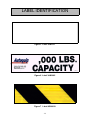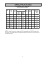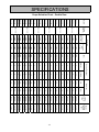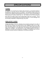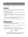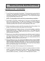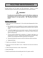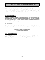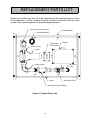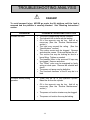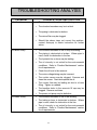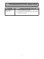
1
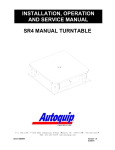
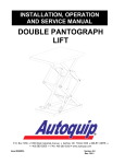
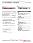
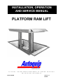
INSTALLATION, OPERATION
AND SERVICE MANUAL
PLATFORM RAM LIFT
P.O. Box 1058
Item # 830RAM
• 1058 West Industrial Avenue Guthrie,
•
OK 73044-1058
•
FAX: 405-282-8105 • www.autoquip.com
405-282-5200 •
Version 1.0
05/2002
TABLE OF CONTENTS
Identification & Inspection
3
Dangers, Warnings, and Cautions
4
Label Identification
8
Specifications
11
Blocking Instructions
14
Installation Instructions
16
Operating Instructions
26
Routine Maintenance
28
General Maintenance
30
Replacement Parts List
34
Troubleshooting Analysis
35
IMPORTANT
Please read and understand this manual prior to installation or operation of this
equipment. Failure to do so could lead to property damage and/or serious personal
injury. If any questions arise, call a local representative or Autoquip Corporation at 1888-811-9876 or 405-282-5200.
PLANNED MAINTENANCE PROGRAM
A local Autoquip representative provides a Planned Maintenance Program (PMP) for
this equipment using factory-trained personnel. Call a local representative or Autoquip
Corporation at 1-888-811-9876 or 405-282-5200 for more information.
2
IDENTIFICATION & INSPECTION
IDENTIFICATION
When ordering parts or requesting information or service on this lift, PLEASE REFER
TO THE MODEL AND SERIAL NUMBER. This information is on a nameplate attached
to the lift platform. Replacement parts are available from a local Autoquip distributor.
INSPECTION
Immediately upon receipt of the lift, a visual inspection should be made to determine
that the lift has not been damaged in transit. Any damage found must be noted on the
delivery receipt. In addition to this preliminary inspection, the lift should be carefully
inspected for concealed damage. Any concealed damage found that was not noted on
the delivery receipt should be reported in writing to the delivering carrier within 48 hours.
The following is a checklist that will aid in the inspection of the lift.
1. Examine entire unit for any signs of mishandling. Pay special attention to the power
unit and controls.
2. Thoroughly examine all connections, making sure they have not vibrated loose
during transit.
3. Check to make sure tat there are no missing parts. If any parts appear to be
missing, contact the Autoquip Customer Assurance Department immediately.
3
DANGERS, WARNINGS & CAUTIONS
SAFETY ALERTS (Required Reading!)
The following SAFETY ALERTS are intended to create awareness of owners,
operators, and maintenance personnel of the potential safety hazards and the steps that
must be taken to avoid accidents. These same alerts are inserted throughout this
manual to identify specific hazards that may endanger uninformed personnel.
Identification of every conceivable hazardous situation is impossible. Therefore, all
personnel have the responsibility to diligently exercise safe practices whenever exposed
to this equipment.
____________________________________________________________
DANGER!
Identifies a hazardous situation that presents the imminent probability of
death or of severe personal injury!!
_____________________________________________________________
WARNING!
Identifies a hazardous situation that has the potential of causing death or
serious personal injury.
________________________________________________________________
CAUTION!
Identifies a hazardous situation that could lead to the possibility of personal
injury of death, and/or may result in equipment damage.
_____________________________________________________________
4
DANGERS, WARNINGS & CAUTIONS
Read and understand this manual and all labels prior to operating or
servicing the turntable. All labels are provided in accordance with
ANSI Z535.4.
DANGER!
Do not work under lift without Maintenance Device! To avoid personal
injury, NEVER go under the platform until the load is removed and the
platform is securely blocked in the open position. See "Blocking
Instructions" section.
DANGER!
To avoid personal injury, stand clear of platform while it is in motion.
DANGER!
Do not install the lift in a pit unless it has a bevel toe guard or other
approved toe protection. A shear point can exist which can cause severe
injury to the foot.
DANGER!
HIGH VOLTAGE!! Disconnect and/or lock out the electrical supply to the
power unit prior to any maintenance being performed.
5
DANGERS, WARNINGS & CAUTIONS
DANGER!
Ram lifts are designed individually for a specific load and application. To
avoid personal injury, do not change the load or application from the
original design.
WARNING!
NEVER stand, sit or ride on the lift.
WARNING!
All warning and information decals should be in place as outlined in the
“Label Identification” section. If decals are missing or damaged, they
should be replaced with new ones. Contact Autoquip for replacements.
WARNING!
Lift platforms traveling below floor levels may create a hazard, and the
shape of the load and how the load is arranged on the platform may create
a toe hazard as the load passes the top edge of the pit. Both situations
may require guarding in accordance with Federal Regulations. Any such
guarding must be installed prior to operating the lift.
WARNING!
To avoid personal injury, NEVER go under the lift platform or perform any
maintenance on the lift until the load is removed and the platform is
securely blocked in the open position. See "Blocking Instructions" section.
6
.
DANGERS, WARNINGS & CAUTIONS
CAUTION!
Do not continue to depress the “UP” button on the controller if the lift is not
raising or if it has reached the fully raised position. To do so may result in
permanent damage to the motor or pump.
CAUTION!
Never run the pump for more than a couple of seconds without pumping oil.
This applies to low oil conditions, improper motor rotation, running the
pump against the relief pressure after the lift is fully raised against the
physical stops, running overloaded beyond capacity, or running at reduced
speed because of pinched or obstructed hydraulic lines.
CAUTION!
Do not operate the power unit on relief for more than a few seconds. When
on relief, the valve will make a squealing sound.
CAUTION!
Precautions should be taken to prevent the introduction of contaminates
such as water, dirt or other foreign material into the system through open
fittings, pipes or disassembled components. Contamination will ruin the
hydraulic system.
CAUTION!
Use only approved oils in the lift.
Maintenance section.
7
See “Oil Requirements” in the
LABEL IDENTIFICATION
3
1
2
4
5
6
6
Figure 1 Label Placement Diagram
Platform Ram Lift
Item No.
Qty
Description
Part No.
1
2
Caution – Familiarize Yourself With Operators Manual
36401487
2
2
Caution – Do Not Go Under Lift Platform . . .
36400679
3
2
Warning – Handrails and snap chains
36403715
4
1
Autoquip Serial Number Nameplate
36401511
5
2
Capacity
36401602
6
1
Safety Striping
06100010
8
LABEL IDENTIFICATION
Note: Labels shown here are not actual size.
Figure 2 Label 36401487
Figure 3 Label 36400679
Figure 4 Label 36403715
9
LABEL IDENTIFICATION
Figure 5 Label 36401511
Figure 6 Label 36401602
Figure 7 Label 06100010
10
SPECIFICATIONS
APE Selection Chart – Single Ram
20,000 lb Rollover Standard
Model
No.
Platform
Size
(in)
Lifting
Cap
(lbs)
APE-0
48x48
APE-1
Axle Load
Centered
Over
Ends
Centered
Over
Sides
6,000
3,500
3,500
48x72
6,000
3,500
3,500
APE-2
72x72
6,000
3,500
3,500
APE-3
72x96
6,000
3,500
3,500
APE-4
72x120
6,000
3,500
3,500
APE-5
96x96
6,000
3,500
3,500
APE-6
96x120
6,000
3,500
3,500
Ram
(qty)
size
Raising
Time
(fpm)
Motor
HP
Approx.
Shipping
Weight
(lbs)
(1)
10Q
(1)
10Q
(1)
10Q
(1)
10Q
(1)
10Q
(1)
10Q
(1)
10Q
7
5
1,540
7
5
1,700
7
5
2,000
7
5
2,300
7
5
2,540
7
5
2,620
7
5
2,940
NOTE: Values shown are for single ram (APE) and double ram (DRAPE) models with
60” travel. Consult the factory for models that travel in excess of 60” or are in excess of
the capacity shown.
11
SPECIFICATIONS
Drape Selection Chart – Double Ram
Drape 12
Drape 11
Drape 10
Drape 9
Drape 8
Drape 6
Drape 5
Drape 4
24,000
20,000
16,000
12,000
24,000
20.000
16,000
12,000
24,000
20,000
16,000
12,000
24,000
20.000
16,000
12,000
Centered
Over Ends
11,000
24,000
16,000
16,000
12,000
24,000
13,000
15,000
10.000
24,000
14,000
16,000
11,000
24,000
20.000
16,000
12,000
Centered
Over
Sides
(2) 12Q
(2) 10Q
(2) 12QSD
(2) 12QEH
(2) 12Q
(2) 10Q
(2) 12QSD
(2) 12QEH
(2) 12Q
(2) 10Q
(2) 12QSD
(2) 12QEH
(2) 12Q
(2) 10Q
(2) 12QSD
(2) 12QEH
(2) 12Q
(2) 10Q
4
4
6
4
4
4
6
4
4
4
6
4
4
4
6
4
4
4
6
Std Motor
8
8
8
12
8
8
8
12
8
8
8
12
8
8
8
12
8
8
8
12
Opt Motor
10
10
7 1/2
7 1/2
10
10
7 1/2
7 1/2
10
10
7 1/2
5
7 1/2
10
7 1/2
5
7 1/2
10
7 1/2
5
7 1/2
Std
15
20
20
15
15
20
20
15
15
20
20
15
10
15
20
15
10
15
20
15
10
15
Opt
25,000
20,000
15,000
30,000
25,000
20,000
15,000
30,000
25,000
20,000
15,000
30,000
25,000
20,000
15,000
30,000
25,000
20,000
15,000
30,000
25,000
20,000
15,000
Lifting
Capacity
(lbs)
10,500
8,850
7,750
6,550
9,850
8,250
7,200
6,100
9,150
7,650
6,700
5,650
9,250
7,700
6,650
5,400
8,700
7,250
6,250
5,000
8,150
6,750
5,850
4,700
Approx.
Shipping
Weight
(lbs)
Motor (hp)
Drape 13
12,000
16,000
(2) 12QEH
4
12
7 1/2
15
30,000
Raising Time (fpm)
Drape 14
16,000
14,000
(2) 12QSD
6
8
7 1/2
20
Axle Load
Drape 16
20.000
24,000
(2) 10Q
4
8
10
Rams
Drape 17
24,000
10.000
(2) 12Q
4
8
Model #
Drape 18
12,000
15,000
(2) 12QEH
4
Platform
Size (in)
Drape 20
16,000
13,000
(2) 12QSD
Drape 23
Drape 19
Drape 15
Drape 7
Drape 3
Drape 2
Drape 1
Drape 21
20,000
24,000
96 x 180
84 x 180
72 x 180
96 x 144
84 x 144
72 x 144
Drape 22
24,000
Drape 24
12
SPECIFICATIONS
LOADING
The hydraulic ram type lift has the capacity rating stamped on a metal plate attached to
the platform on one side of the lift. This figure is a net capacity rating for the lift as
furnished when shipped from the Autoquip factory. The relief valve of the pumping unit
has been set to raise the indicated amount of capacity plus a small amount of overload.
Where gravity-roll sections, special tops, etc., are installed on the lift after leaving the
plant, deduct the weight of these from the load rating to obtain the net capacity. The lift
should never be overloaded beyond the established capacity, as serious damage to the
ram assembly, the platform, and possible injury may result.
UNBALANCED LOADING
Unbalanced loadings of the lift is indicated on the nameplate showing the four sides of
the lift and the maximum axle loads that the lift was designed to take over its sides.
Axle load ranges stated as such take into account a 50% impact factor from rolling
loads, and the equipment is stressed to take such loading on the standard platform as
shipped from Autoquip. Any modifications of the standard platforms will result in
deterioration of the axle load ratings across the edges of the platform and the factory
should be consulted should any modifications in the field be considered.
13
BLOCKING INSTRUCTIONS
DANGER!
HIGH VOLTAGE!! Disconnect and/or lock out the electrical supply to
the power unit prior to any maintenance being performed.
APE
1. Unless specified otherwise, the non-rotator pipe (if installed) should be disconnected
and the platform rotated 45º from it's home position.
2. The ram and platform are then lowered slowly by pressing the “DOWN” button until
the platform rests safely on the floor above the pit opening.
WARNING!
To ensure a safe and stable descent, make sure all personnel and
equipment are clear of the unit as it is lowered.
3. Continue holding the “DOWN” button for 10 – 15 seconds after the platform comes
to rest on the floor to ensure that all hydraulic pressure in the system is removed.
4. Once the work is complete, raise the lift by pressing the “UP” button and lift the
platform three to four feet above floor level.
5. Rotate the platform back into the home position and reconnect the non-rotator pipe.
DRAPE
1. Unless otherwise specified, most dual-ram lift platforms rest on curbs or bumpers in
a pit that is a minimum of 24” – 36” deep. Press the “DOWN” button to bring the
platform to rest on these curbs, or other sturdy supports, onto all four corners of the
platform.
14
BLOCKING INSTRUCTIONS
2. If more than 24” – 36” headroom is required, the lift platform can also be blocked
open using one of the following approved procedures:
A. Raise the lift past floor level and lay structural steel members diagonally across
each of the four corners of the pit opening. These steel members must be of the
same size and weight of the primary substructure members of the platform.
Slowly bring the platform to rest on these steel members.
B. Place jack stands under each of the four corners of the platform. The jack stands
must be rated to stand the total weight of the platform plus the weight of the
rams. To avoid damage to the deck, a large plate should be placed between the
jack and the underside of the platform deck if the jack cannot be placed
underneath a structural member. Slowly bring the platform to rest on the jack
stands.
WARNING!
If the platform is left on jack stands and the rams(s) removed, care
must be taken to prevent side impacts to the platform that could
cause the stands to deflect or move and cause the platform to fall.
3. Continue holding the “DOWN” button for 10 – 15 seconds after the platform comes
to rest on the floor or stands to ensure that all hydraulic pressure in the system is
removed.
4. Once the work is complete, raise the lift by pressing the “UP” button.
15
INSTALLATION INSTRUCTIONS
Read these instructions completely before starting the installation process.
SITE INSPECTION
The following site verification should be conducted prior to beginning ram installation.
1. Check the pit length and width dimensions to ensure that there is a minimum
platform clearance of _” per side.
2. Check the pit diagonal distances to ensure that there is pit squareness and proper fit
of the platform into the pit opening.
3. If the platform is to travel below the floor level, check all of the pit walls for
plumbness and ensure that the platform will maintain a minimum _” clearance with
the pit wall.
4. Consider all of the overhead obstructions (piping, utilities, building structure, cranes,
etc.) that may interfere with the handling and setting of the ram.
5. Ensure that there is adequate depth and surrounding space to properly set the
ram(s).
POWER UNIT INSTALLATION
1. For best performance, power units should be installed within 25 feet of the ram lift
and no higher in elevation than 12 feet above floor level.
2. Fill the reservoir with the recommended oil (see “Oil Requirements” in the
Maintenance Section).
3. Mount the control panel and connect the primary power to the panel.
4. Mount the pushbutton station(s) and run the secondary power from the panel to the
pushbutton, and from the pushbutton to the motor and down solenoid valve.
DANGER!
HIGH VOLTAGE!! Disconnect and/or lock out the electrical supply to
the power unit prior to any maintenance being performed.
16
INSTALLATION INSTRUCTIONS
RAM INSTALLATION – APE AND DRAPE
1. Do not lift the ram assembly by the plunger. A sling should be secured under the
ram flange. The shipping wire on the end of the ram that was installed at the factory
should be kept intact until it is time to operate the ram. This will prevent the plunger
from turning and falling inside the casing.
NOTE: The ram plunger surface must not be scratched during installation!
2. If the footing is not pre-set, suspend the ram in the hole at the proper height and
block it into a plumb position. For single ram installation, be careful to properly
orient the non-rotator pipe, when used. For dual ram installation, use the spreader
channels to properly position the rams for cable equalization, when used.
3. Plumb in all planes by using a spirit level horizontally across the top edge of the
plunger. Re-check with a level at right angles across the plunger.
4. Connect the elbow and riser pipes to the ram. For dual ram installation, connect the
piping between the rams. Temporarily cap the top end. Use suitable pipe joint
compound on all male threads. Make sure the riser comes to at least 12” above the
finished elevation of the pit floor.
5. When the ram is reasonably level and centered, pour sufficient concrete to make the
footing come up several inches above the bottom of the cylinder. Do not encase
the entire cylinder length in concrete, or the ram casing removal will be
impossible. Allow the concrete to set for 24 hours.
6. Begin backfilling with clean sand. Do not use cinders or other corrosive backfill
anywhere near the cylinder or the piping. Fill the hollow ram-plunger with clean
sand. This ballast is absolutely necessary for the rams to come down unloaded for
proper lift performance and service convenience. Do not put any foreign material
into air-over-hydraulic plungers; this will ruin the ram.
NOTE: Prevent sand or dirt from getting around the seal-ring recess.
7. Tamp the backfill well and continue to recheck for proper centering, non-rotator
position, and always recheck that the cylinder is plumb. Off-center positioning of
1/8” is acceptable, but 1/16” off level across the 10 _” diameter plunger will indicate
that the cylinder is more than _” off plumb in its 90-inch length (for 60” travel).
17
INSTALLATION INSTRUCTIONS
NOTE: Many times the footing will not set early enough to support the cylinder
weight, so it must remain suspended. A poorly centered suspension or sling may
try to pull the cylinder out of plum, even though it is fully backfilled. This is why the
plumb of the cylinder should be re-checked often while backfilling, the suspension
should be reasonably centered, and should be braced back to the pit walls or
wedged with blocks at the top until the sling is removed. Do not use a sledge to
drive the wedges as the cylinder may be damaged.
8.
Install the reinforcement bar in the pit floor before the “top cap” of concrete is
poured to finish the pit floor. If this rebar is not installed, the top cap may sink into
the backfill beneath.
PIPING INSTALLATION
1. Install piping between the ram inlet port (in the pit) and piping entering the pipe
chase in the pit wall, and between the “stub up” out of the pipe chase to the power
unit discharge port. Piping should be steel with a minimum wall thickness of
schedule 40, and a diameter no smaller than the oil coupling connection on the
ram(s).
2. To avoid introducing harmful debris into the piping, do not use Teflon tape; use pipe
dope such as Loctite PST #567. Also, an air compressor should be used in the
piping previously installed to blow out any possible debris in the pipe chase which
my have been introduced during site construction.
3. Be sure to install at least one to two union fittings in the pit to allow for future
maintenance by providing a means to drop the pipe manifold without removing the
ram(s). A block valve installed near the riser in the pit will also prove useful for
future maintenance by providing a means to block oil in the piping from the power
unit.
4. It is best to leave enough space for a pipe wrench between the pit floor and the
bottom of the pipe run.
NOTE: For proper air-valve performance in APA (air-powered) models, the “IN” port
must be connected to an air supply line and the “OUT” port to exhaust only.
18
INSTALLATION INSTRUCTIONS
RAM START-UP PROCEDURE
1. Pre-fill all piping and ram(s) with oil.
2. Ensure that the factory shipping wire holding the ram plunger in position is removed
before operating the ram(s).
3.
Apply pressure to raise the ram about three feet. Loosen the bleeder screw in the
flange two to three turns. Air trapped in the bearing space will escape. Leave the
ram in this half-raised position until all of the bleeder air has escaped and clear,
bubble-free oil runs from the bleeder. Allow plenty of time for this procedure.
4.
Tighten the bleeder screw until snug. Don’t over tighten the screw as this can
cause damage to the rubber seal washer.
5.
Clean away all dirt, cement, sand, etc, from around the plunger and seal flange.
Pour a little oil around the seal and raise the lift a few inches to carry up any
remaining dirt particles.
6.
Wipe the plunger clean, lower it to the ground, and refill oil to the proper level.
7.
Raise the lift to its full height and apply full pressure to the system.
8.
Lower the lift slightly below full rise and crack open the bleeder screw again to
ensure that all air is out of the system. Re-tighten the bleeder screw.
9.
While full pressure is on the system, check all piping thoroughly for leaks.
10. If it is leak free, complete the backfilling and pour the concrete “top cap” in the pit
floor. Keep dirt and concrete away from the plunger and packing flange, as well as
the cable equalizer struts, when applicable. Wipe the plunger with an oil soaked
cloth to prevent rusting.
11. Let the concrete set for at least 24 hours, then recheck the plunger and seal-flange
for cleanliness.
SUMMARY – RAM INSTALLATION & START-UP
1. Set the rams in the pit. Be absolutely sure the rams are on pit centerline.
2. Brace against the pit walls.
3. Connect the oil lines between the power unit and the rams.
19
INSTALLATION INSTRUCTIONS
4. Run the rams up to full height. Test for leaks.
5. Plumb the rams by leveling them from the side of the plunger on all four planes. As
a backup measure only, the rams may be plumbed from the top using a precision
straight edge. However, this alone does not ensure a proper plumb.
6. If the rams are absolutely plumb and parallel, backfill and lower the rams. Cement
around the openings.
7. Let the concrete set for 24 hours or more.
PLATFORM INSTALLATION – APE
1. Lower the ram all the way and loosely bolt the ram to the bolster plate underneath
the platform in the correct orientation using the hardware provided.
2. Raise the lift, and then pull up the non-rotator pipe and bolt it loosely to the
superstructure underneath the lift platform.
3. Lower the lift all the way to check for clearance with the pit walls, and then position
and tighten the bolts to the superstructure.
4. Tighten the non-rotator pipe.
5. The lift is ready to operate and should raise and lower freely if the non-rotator pipe is
correctly adjusted and not binding at the bottom of the stroke.
PLATFORM INSTALLATION – STRUCTURALLY EQUALIZED DRAPE
1. The rams must have all the air bled out to ensure that they will remain synchronized
after the platform is attached.
2. Lower the rams all the way, then position and bolt the bolster plated located
underneath the platform in correct orientation using the hardware provided. If
visibility is too poor, raise the lift out of the pit to get enough light to see the bolt
holes. Also, a tapping tool may have to be used to clear the threads in the end of
the plunger of all sand and concrete that may have accumulated.
3. The lift is ready to operate and should raise and lower freely without binding the
rams at any point of the lift travel. Binding will cause the lift to bounce or jerk during
operation
4. Tighten all bolts.
20
INSTALLATION INSTRUCTIONS
PLATFORM INSTALLATION – CABLE EQUALIZED DRAPE
1.
The rams must have had all the air bled out to ensure that they will remain
synchronized after the platform is attached.
2.
Lower the rams all the way, then position and bolt the bolster plated located
underneath the platform in correct orientation using the hardware provided. If
visibility is too poor, raise the lift out of the pit to get enough sight to see the bolt
holes. Also, a tapping tool may have to be used to clear the threads in the end of
the plunger of all sand and concrete that may have accumulated.
3.
Unwind the cable from each of the strut assemblies and lay it out on the pit floor.
One end will have been attached at the factory.
4.
Raise the struts and bolt them both to the bottom of the bolster plate with the
hardware provided.
5.
Before the cables are tightened, raise the rams to full travel.
6.
Make sure that both eye-bolts on the bolster plate are backed out as far as
possible, then begin taking out all slack in each cable and tighten as much as
possible. Use a “come-along” or other mechanical device to tie off to the opposite
ram and tighten until it is impossible to tighten it further.
7.
As the cable is tightened, the spare cable length will grow longer on the free end.
Do not cut off any spare cable until the tightening is completely finished and
the lift is commissioned for use.
8.
While tightening and taking up cable around the end thimble, the thimble will try to
rotate with the cable being pulled past it. Use a hammer or other tool to keep the
thimble in the correct position.
9.
Once all of the tightening at the free end is complete, cut off the excess cable.
10. Go back to the eye-bolts on the bolster and attempt to tighten the cable further by
screwing the eye-bolts in.
11. When work with the cable is complete, the cable can be stood upon with no visible
deflection.
12. Run the lift through full travel several times to ensure that the platform is level in
the fully raised position.
21
INSTALLATION INSTRUCTIONS
HAS TO BE
LEVEL BOTH WAYS
PRECISION-STRAIGH
-D
T
E
G
LEVEL
NO CLEARANCE UN
ER
D
(4) POI
S
T
N
MUST BE SAME
DIMENSION TOP AND
BOTTOM ± 1/64"
Figure 8 Leveling Rams
22
INSTALLATION INSTRUCTIONS
18 "
TYP.
18 "
TYP.
CONCRETE BUMPERS
( 4 ) CORNERS
( BY PIT CONTRACTOR)
WASHER PLATE
& RAM BOLTS
12"
PLATFORM
WIDTH
"A"
"A"
RAM LOCATED IN
CENTER OF PLATFORM
PIT
WIDTH
(PLATFORM
WIDTH + 2" )
36" ROUND OR SQUARE OPENING IN
PIT FLOOR FOR SETTING RAM.
HANDRAILS AND
SNAP CHAINS NOT
SHOWN FOR CLARITY.
1 " TYP.
PLATFORM LENGTH
1 " TYP.
PIT LENGTH
(PLATFORM LENGTH + 2" )
REMOTE POWER UNIT:
LOCATE WHERE CONVENIENT.
NON-ROTATOR ASS,Y.
LIFT
TRAVEL
BEVEL TOE GUARDS ON ( 4)
SIDES WITH YELLOW AND
BLACK STRIPED TAPE.
ELBOW
RAM SETTING DIM.
FROM FLOOR LEVEL TO
TOP OF RAM FLANGE.
CURB ANGLES
(BY OTHERS)
1 3"
UNION
PIPE CHASE
(BY OTHERS)
36" APPROX.
PIT DEPTH
RAM LENGTH
OIL LINE TO RUN BEFORE
CONCRETE IS POURED.
UNION
CONCRETE BUMPERS
TYP. ( 4) CORNERS
( BY OTHERS)
9 " ROUND OR SQUARE OPENING
FOR SETTING NON-ROTATOR
(BY OTHERS).
REINFORCING BAR
WELDED TO CASING
(BY PIT CONTRACTOR)
CLEAN SAND BACKFILL
(BY INSTALLER)
36 " DIA. X 1 /4" WALL
STEEL CASING, IF REQUIRED
( BY PIT CONTRACTOR)
FOOTING
SECTION "A-A"
Figure 9 General Arrangement - APE
23
INSTALLATION INSTRUCTIONS
" PIT LENGTH
(PLATFORM LENGTH + 2" )
"PIT WIDTH
18"
TYP.
"A"
(PLATFORM WIDTH + 2")
18"
TYP.
"A"
RAM C.L.
HANDRAILS AND
SNAP CHAINS NOT
SHOWN FOR CLARITY.
CURB ANGLES
( BY PIT CONTRACTOR)
CONCRETE BUMPERS
( 4) CORNERS
(BY PIT CONTRACTOR)
1" TYP.
REMOTE POWER UNIT
LOCATE WHERE CONVENIENT
1 " TYP.
LIFT
TRAVEL
BEVEL TOE GUARDS ON ( 4)
SIDES WITH YELLOW AND
BLACK STRIPED TAPE.
ELBOW
RAM SETTING DIM
TO TOP OF RAM FLANGE
RAM WASHER
PLATE
UNION
OIL LINE TO RUN BEFORE
CONCRETE IS POURED
3 6" APPROX.
PIT DEPTH
CONNECTING PIPE
(BY PIT CONTRACTOR)
RAM
TIE ROD
REINFORCING BAR
WELDED TO CASING
(BY PIT CONTRACTOR)
FOOTING
CLEAN SAND BACKFILL
(BY INSTALLER)
RAM LENGTH
PIPE CHASES
(BY PIT CONTRACTOR)
4 2" X 42" X 1 / 4" WALL
STEEL CASINGS
(BY PIT CONTRACTOR)
FOOTING
SECTION " A-A"
Figure 10 General Arrangement – DRAPE
24
UNION
(TYP)
25
Figure 11 Cable Threading Diagram
OPEN SOCKET
FOR CABLE B
CABLE B
CABLE B
STRUT TUBE
EQUALIZER STRUT
PIT CHANNEL
SHEAVES
CABLE A
CABLE A
CABLE B
EYE BOLT
THIMBLE
CABLE CLIPS
TO
CL
RAMCL
OPEN SOCKET
FOR CABLE A
CABLE A
CABLE A
THIMBLE
CABLE B
EXTRA HEAVY
RAM DUAL
OIL LINE COUPLING
INSTALLATION INSTRUCTIONS
OPERATING INSTRUCTIONS
Familiarize yourself with this operator’s manual before operating the equipment!!!
The remote self-contained power unit consists of an electric motor directly coupled to a
pump with a suction filter, check valve, relief valve, and solenoid down valve mounted to
a reservoir.
1. Ram lifts have maximum lifting capacity ratings (see “Specifications” section). The
safety relief valve has been factory set to open at a pressure slightly above the rated
load capacity and allows the oil to bypass into the reservoir to prevent damage to the
lift and its hydraulic power unit. The safety relief valve should not be adjusted for
any reason as it could cause the motor to prematurely burn out. Applying loads
exceeding the rated capacity of the lift may result in excessive wear and damage to
the lift.
2. This type of lift is typically furnished with constant pressure pushbutton controls.
Actuating the "UP" button will cause oil to enter the ram(s) and the lift will rise.
3. When the desired height or upward travel of the platform is attained, removing
pressure from the button deactivates the “UP” circuit. The oil stops flowing and the
upward movement will stop.
4. Activate the "DOWN" button to lower the lift. Opening the down control valve allows
the oil in the ram(s) to flow through the down valve at a controlled rate and return oil
to the reservoir.
5. When the desired height or downward travel of the platform is attained, removing
the operator’s hand from the button deactivates the “DOWN” circuit. The oil stops
flowing from the ram(s) and the downward movement will stop.
CAUTION!
Do not continue to activate the "UP" button if the lift is not raising or if it
has reached the fully raised position. To do so may result in permanent
damage to the lift.
26
OPERATING INSTRUCTIONS
CAUTION!
Do not operate the power unit on relief for more than a few seconds. When
on relief, the valve will make an audible squealing sound.
All automatic controls added to the lift must include provisions for immediately shutting
off the pumping unit at the top travel of the lift, and releasing the solenoid at the bottom
travel of the lift.
CAUTION!
Care should be taken when loading the platform lift to insure that the
“Rated Axle Load Capacity” and the “Lifting Capacity” is not exceeded.
Overloading can cause damage or failure to the equipment and can result
in personal injury.
27
ROUTINE MAINTENANCE
Normally platform ram lifts require very little maintenance. However, a routine
maintenance program could prevent costly replacement of parts and/or downtime.
WARNING!
To avoid personal injury, NEVER go under the lift platform or perform any
maintenance on the lift until the load is removed and the platform is
securely blocked in the open position. See "Blocking Instructions"
section.
MONTHLY INSPECTION:
1. Check oil level (see “Oil Requirements” in this section) and add appropriate oil when
necessary.
a. Rams already in service need prefilling to the proper checkpoint before bleeding,
only when they are suspected of having less than two-thirds of their normal oil
supply.
b.
To bleed the trapped air from rams already in service: Raise the empty lift half
way and loosen the bleeder plug four turns. When the oil comes out air-free,
tighten the bleeder plug.
c.
All rams should be lowered fully to check the oil. However, when there is no
superstructure on the ram, it should not be lowered below the cylinder flange,
except for seal-ring replacement and/or cleaning the seal-ring groove.
d.
Remove the fill plug of the reservoir and fill it to within two inches from the top.
e.
Replace the fill plug.
2. Check for any visible leaks. Correct as necessary.
3. Check any unusual noise when it occurs. Determine the source and correct as
necessary.
4. Check all wiring for looseness or wear. Repair at once.
5. Keep all bolts tight.
6. Keep the superstructure and surrounding area free of oil, grease, and dirt.
28
ROUTINE MAINTENANCE
7. Use caution in determining the need for repacking. Know the difference between
controlled “weepage” which is necessary for lubricating the packing and “leakage”
beyond toleration. A dry-wiping packing is not necessary. The perfect packing
leaves an oil film that can be felt but not seen on the piston.
OIL REQUIREMENTS:
Change oil if it darkens materially or feels gummy or gritty. Do not use hydraulic-jack
oil, hydraulic fluids, brake fluids, or automatic transmission fluid. Use only oils that are
100 to 150 SSU at 100º F. Call the Autoquip Customer Assurance Department for
recommended brands, if necessary.
OIL CAPACITY:
Reservoir capacity (gallons) for the steel tank can be approximated by the following
formula:
Tank Width X Length X Height (in inches)
231 (cubic inches per gallon)
PIPE THREAD SEALANT
Loctite PST #567 pipe thread sealant or equivalent is recommended. Do not use
Teflon tape. Tape fragments can cause malfunctioning of the hydraulic system.
29
GENERAL MAINTENANCE
CAUTION!
Never run the pump for more than a couple of seconds without pumping
oil. This applies to low oil conditions, improper motor rotation, running the
pump against the relief pressure after the lift is fully raised against the
physical stops, running overloaded beyond capacity, or running at reduced
speed because of pinched or obstructed hydraulic lines.
PUMPS
Pumps cannot be field repaired, nor should they be taken apart. Wear or any internal
damage occurs to the gears and to the pump body, making pump repair impractical.
Complete replacement is necessary when the pump becomes defective.
GOULD SOLENOID VALVES
Piston pilot operated Gould solenoid valves should last for years in general applications.
The coil assemblies are replaceable by removing one screw. Should the lift “creep”
down, the valve seat can be cleaned by removing the bonnet nut without taking the
valve from the pipeline. Take care not to damage or force the plunger stem over which
the coil is assembled. The lift must be fully lowered to relieve all pressure before
dismantling. When removing the bonnet, the valve should be restrained by using a
wrench on the hex flats at the pipe ports, not on the body. Oil that is too heavy for
existing temperature will cause a sluggish valve action or refusal to open when under
full-load pressure. These valves need a minimum pressure drop of 5 psi across the
valve to operate.
.
30
GENERAL MAINTENANCE
Figure 12 Gould Solenoid Valve
31
GENERAL MAINTENANCE
REPLACING RAM SEALS
1. Block the superstructure (see “Blocking Instructions”) and unbolt the platform bolster
plate from the ram(s). It is recommended to mark the plunger and bolster with a
chalk mark or paint to be able to orientate the plunger when re-attaching.
NOTE: Do not allow the plunger to rotate 120 degrees during disassembly or it will
drop below the surface of the seal flange.
2. Raise the ram several inches and clean thoroughly around the plunger and sealflange to prevent the possibility of any dirt particles from entering the seal space
while servicing. If the top edge of the ram is rust-marked, it must be polished
smooth or it will not pass through the seal.
3. Apply a light coat of grease around the ram. Lower until it bottoms about a half inch
below the seal groove. If the lowering ram hits solid at about 3/8” above the sealflange, rotate it until the arrow stamped in the head plate points toward the bleeder
screw, then finish lowering. The seal should now be exposed.
4. Remove the old seal.
compressed air.
Inspect and clean the seal groove using a rag and
5. If foreign matter drops down around the ram, remove as much as possible with an
oil-soaked cloth and/or compressed air. Remove the seal ring and apply pressure to
the system to raise the ram about six inches so that residual dirt particles will cling to
its sides where it can be wiped off. Ignore a slight loss of oil around the ram while it
is raised. When the ram is clean, lower it again,
6. Install the new Wiper-seal in the seal groove by pinching the seal as shown in Figure
15a. Work it all the way around with an inside loop in the seal as shown in Figure
15b.
7. Press the ring tightly into the groove with finger pressure. The ring must be straight
and well seated in the groove before raising the piston. Apply a coating of grease to
the new seal.
8. Using a slow jogging action, inch the ram up past the seal, being sure not to pinch it
as it may squeeze out of the groove. Do not raise the ram all the way up without
reinstalling the superstructure. The friction of the new seal may prevent it from
lowering when empty.
32
GENERAL MAINTENANCE
Figure 13a
Figure 13b
33
REPLACEMENT PARTS LIST
Specific part numbers vary from job to job, depending on the model and options chosen
for the application. Call the Autoquip Customer Assurance Department with the serial
number of the specific equipment to order the appropriate parts.
SUCTION LINE W/ FILTER(S)
OIL RESERVOIR
FILLER BREATHER
COUPLINGS
AND SPIDER
MOTOR
RELIEF VALVE
PUMP
CHECK VALVE
RETURN
LINE
DRAIN
SOLENOID VALVE
PRESSURE LINE TO RAM(S)
Figure 14 Typical Power Unit
34
TROUBLESHOOTING ANALYSIS
DANGER!
To avoid personal injury, NEVER go under the lift platform until the load is
removed and the platform is securely blocked. See "Blocking Instructions"
section.
PROBLEM
POSSIBLE CAUSE AND SOLUTION
Lift does not raise.
• The motor voltage/wiring may be incorrect.
• The hydraulic line or hose may be leaking.
• Oil in the reservoir may be low. Add oil as
necessary (See the “Routine Maintenance”
section.)
• The load may exceed the rating. (See the
“Specifications” section.)
• The suction screen may be clogged. Remove
and clean the screen. Drain and replace the oil.
• The suction line may be leaking air due to a
loose fitting. Tighten as needed.
• The breather holes in the reservoir fill cap may
be clogged. Remove and clean.
• The "Down" valve may be energized by faulty
wiring or stuck open. Remove the solenoid and
check.
• The power unit pump may be defective
• The structural members of the lift may be in a
bind.
Lift seems bouncy during
operation.
• There may be air in the hydraulic system.
Bleed the air from the cylinder
• Oil in the reservoir may be low. Add oil as
necessary (See the “Routine Maintenance”
section.)
• The power unit suction strainer may be clogged.
• The power unit suction line may be leaking.
35
TROUBLESHOOTING ANALYSIS
PROBLEM
Lift will not lower.
POSSIBLE CAUSE AND SOLUTION
• The down solenoid may be malfunctioning.
• The structural members may be in a bind.
• The piping is obstructed or broken.
• The return filter may be clogged.
• Should the above steps not correct the problem,
contact Autoquip to obtain instruction for further
action.
Lift raises slowly.
• The structural members of the lift may be binding.
• The piping is obstructed or broken. Where pipe is
used, check for obstruction in the line.
• The hydraulic line or hose may be leaking.
• The oil viscosity is not suited for the environmental
conditions. Refer to “Routine Maintenance” section
for oil requirements.
• Check the oil level in the reservoir.
• The motor voltage/wiring may be incorrect.
• The suction screen may be clogged. Remove and
clean the screen. Drain and replace the oil.
• The suction line may be leaking air due to a loose
fitting. Tighten as needed.
• The breather holes in the reservoir fill cap may be
clogged. Remove and clean.
• The power unit pump may be defective.
Lift lowers slowly.
• The structural members of the lift are binding.
• The tubing or hose is obstructed or broken. Where
pipe is used, check for obstruction in the line.
• The oil viscosity is not suited for the environmental
conditions. Refer to “Routine Maintenance” section
for oil requirements.
36
TROUBLESHOOTING ANALYSIS
PROBLEM
Lift will not remain in
raised position.
POSSIBLE CAUSE AND SOLUTION
• The ram packing may be leaking.
• The Gould valve or swing check valve is not seating.
• The piping is leaking oil.
37