1
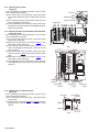
3.1.19 Removing the head phone board
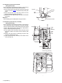
(See Figs.24 and 25)
• Prior to performing the following procedures, remove the top
cover, side panels, stay bkt and front panel assembly.
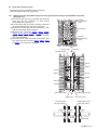
(1) From the top side of the main body, disconnect the wires
from the connector CN738 on the power amp. board. (See
fig.25)
(2) From the front side of the main body, remove the nut a
fixing the head phone board. (See fig.24)
(3) Remove the screw W attaching the lug wire and bracket.
(See fig.24)
Lug wire
Bracket
Nut a
W
Reference:
When attaching the screw W, attach the lug wire with it.
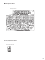
Head phone board
Fig.24
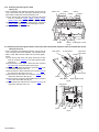
3.1.20 Removing the power amp. assembly
(See Figs.25 and 26)
• Prior to performing the following procedures, remove the top
cover, side panels, stay bkt, rear panel, front panel assembly,
system control board, DSP 1 board, DSP 2 board, audio signal
1 board, audio signal 2 board, video board, S video board, V
compo 1 board and speaker relay board.
(1) From top side of the main body, remove the three screws
X fixing the barriers, and remove the tow barriers. (See
fig.25)
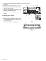
(2) Remove the eight screws Y attaching the power amp.
assembly. (See figs.25 and 26)
(3) Take out the power amp. assembly in the direction of the
arrow. (See fig. 26)
X
Barrier
Power
amp.
assembly
Power
amp.
board
X
Y
Y
CN738
Fig.25
Power amp. assembly
Y
Fig.26
1-12 (No.MB177)