1
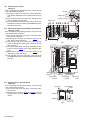
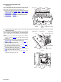
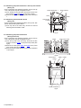
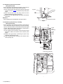
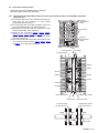
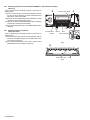
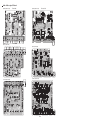
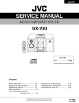
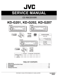
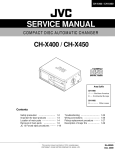
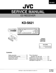
3.1.3 Removing the front panel assembly
(See Figs.3 to 6)
• Prior to performing the following procedure, remove the top
cover, side panels and stay bkt.
(1) From the top side of the main body, cut off the tie band
fixing the wire. (See fig.3)
(2) Remove the three screws F attaching the front panel
assembly. (See fig.3)
(3) Remove the screw G attaching the lug wire. (See fig.3)
(4) From the bottom side of the main body, remove the four
screws H attaching the front panel assembly and take out
the front panel assembly forward. (See fig.4)
(5) From the front side of the main body, disconnect the wire
from the connectors CN971, CN977, CN983 and CN985
on the system control board. (See fig.5)
(6) From the reverse side of the front panel assembly,
disconnect the wire from the connector CN973 on the front
AV in board. (See fig.6)
(7) Disconnect the wire from the connector CN373 on the front
DIGITAL in board. (See fig.6)
Reference:
When attaching the screws F and screw G, attach the lug wire
with it.
F
Front panel assembly
G
(fixing the
lug wire)
Tie band
Fig.3
H
Front panel
assembly
Fig.4
System control board
CN985
CN983
CN977
CN971
Fig.5
CN973
Front AV in board
CN373
Front DIGITAL in board
Fig.6
(No.MB177)1-5