1
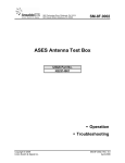
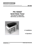
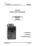
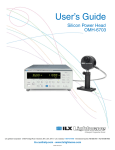
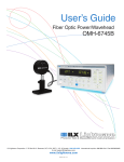
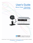
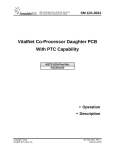
Union Switch & Signal Inc., an Ansaldo Signal company
1000 Technology Drive, Pittsburgh, PA 15219
645 Russell Street, Batesburg, SC 29006
SM 6810B
SML-110
Switch Machine Lock
US&S Part No.
N47302301
N47302302
PN-150SSR
Solid-State Relay
US&S Part No.
N40103601
♦ Description
♦ Installation
♦ Operation
♦ Maintenance
Copyright © 2008
Union Switch & Signal Inc.
Rev. 1
January 2008
Notices
Proprietary Notice
This document and its contents are the property of Union Switch & Signal Inc. (hereinafter
US&S). This document has been furnished to you on the following conditions: no right or
license under any patents or any other proprietary right in respect of this document or its
content is given or waived in supplying this document. This document and its contents are
not to be used or treated in any manner inconsistent with the rights of US&S, or to its
detriment, and are not to be copied, reproduced, disclosed to others, or transferred without the
prior written consent of US&S.
Important Notice
US&S constantly strives to improve our products and keep our customers apprised of changes
in technology. Following the recommendations contained in the attached service manual will
provide our customers with optimum operational reliability. The data contained herein
purports solely to describe the product, and does not create any warranties.
Within the scope of the attached manual, it is impossible to take into account every eventuality
that may arise with technical equipment in service. Please consult your local US&S Account
Executive in the event of any irregularities with our product.
We expressly disclaim liability resulting from any improper handling or use of our equipment,
even if these instructions contain no specific indication in this respect. We strongly
recommend that only approved US&S spare parts be used as replacements.
SM 6810B, Rev. 1, January 2008
i
Revision History
Revision History
ii
Rev.
Date
Nature of Revision
Original
October 2001
Original Issue
1
January 2008
Incorporate ECO 140292-1: changed 23 amps
output current to 24 amps throughout text and
in Figure 1-4; removed wiring in center view of
parts location diagram (Figure 10-2). Included
new installation views in Section 3 and
reworked text. Included parts lists and
associated parts location diagrams in
Section 10.
SM 6810B, Rev. 1, January 2008
Table of Contents
Table of Contents
1
Introduction............................................................................................................................................................... 1-1
1.1
Introduction........................................................................................................................................ 1-1
1.2
General Application – SML-110 and PN-150SSR ............................................................................ 1-1
1.3
Specifications .................................................................................................................................... 1-5
1.3.1 SML-110 Switch Machine Lock................................................................................................. 1-5
1.3.2 PN-150SSR Solid-State Relay.................................................................................................. 1-5
1.4
SML-110 Output Characteristics ....................................................................................................... 1-6
1.5
Conventions in Manual...................................................................................................................... 1-7
1.5.1 Abbreviations, Acronyms, and Symbols ................................................................................... 1-7
1.5.2 Definitions.................................................................................................................................. 1-7
1.6
Safety ................................................................................................................................................ 1-7
2
Equipment Description ........................................................................................................................................... 2-1
2.1
SML-110 Switch Machine Lock......................................................................................................... 2-1
2.2
PN-150SSR Solid-State Relay .......................................................................................................... 2-1
3
Installation................................................................................................................................................................. 3-1
3.1
Hardware ........................................................................................................................................... 3-1
3.2
Equipment Rack Mounting and Wiring.............................................................................................. 3-1
3.2.1 SML-110 Installation ................................................................................................................. 3-1
3.2.2 Surge Protection for SML-110................................................................................................... 3-2
3.2.3 150SSR Relay Installation ........................................................................................................ 3-2
4
Commissioning ........................................................................................................................................................ 4-1
5
Operating Procedures............................................................................................................................................. 5-1
6
Field Maintenance.................................................................................................................................................... 6-1
6.1
Schedule............................................................................................................................................ 6-1
6.2
Periodic Inspections .......................................................................................................................... 6-1
6.3
Calibration ......................................................................................................................................... 6-1
6.4
Adjustment......................................................................................................................................... 6-1
7
Shop Maintenance ................................................................................................................................................... 7-1
8
Troubleshooting....................................................................................................................................................... 8-1
8.1
General Information........................................................................................................................... 8-1
8.2
Switch Machine Lock SML-110......................................................................................................... 8-1
8.3
PN-150SSR Solid-State Relay .......................................................................................................... 8-2
9
Repairing/Replacing Components........................................................................................................................ 9-1
10
Parts Lists ............................................................................................................................................................... 10-1
10.1 Parts List for SML-110 Switch Machine Locks................................................................................ 10-1
10.2 Parts List for Solid-State Relay PN-150SSR (N40103601) ............................................................ 10-8
11
Technical Support.................................................................................................................................................. 11-1
SM 6810B, Rev. 1, January 2008
iii
Table of Contents
List of Figures
Figure 1-1 - SML-110 and PN-150SSR ...................................................................................................1-2
Figure 1-2 - SML-110 Control of Two Switch Machines (2 Wire) ............................................................1-3
Figure 1-3 - SML-110 Control of Two Switch Machines (3 Wire) ............................................................1-4
Figure 1-4 - SML-110 Output Characteristics ..........................................................................................1-6
Figure 3-1 - SML-110 Installation Views ..................................................................................................3-4
Figure 3-2 - PN-150SSR Installation Views .............................................................................................3-5
Figure 3-3 - SML-110 Surge Protection ...................................................................................................3-6
Figure 5-1 - Relay Circuit .........................................................................................................................5-2
Figure 10-1 - Parts Location for SML-110 Switch Machine Locks (N47302301 and N47302302)........10-6
Figure 10-2 - Parts Location for SML-110 Switch Machine Locks (N47302301 and N47302302)........10-7
Figure 10-3 - Parts Location for Solid-State Relay PN-150SSR (N40103601) ...................................10-10
List of Tables
Table 1-1 - Specifications for SML-110 Switch Machine Lock.................................................................1-5
Table 1-2 - Specifications for PN-150SSR Solid State Relay..................................................................1-5
Table 5-1 - Operation Table for SML-110 and PN-150SSR Combinations .............................................5-2
Table 10-1 - Switch Machine Lock SML-110 N47302301 Parts List .....................................................10-1
Table 10-2 - Switch Machine Lock SML-110 N47302302 Parts List .....................................................10-3
Table 10-3 - Solid-State Relay PN-150SSR N40103601 Parts List ......................................................10-8
iv
SM 6810B, Rev. 1, January 2008
Introduction
1
Introduction
1.1
Introduction
This service manual provides descriptive information, specifications, and instructions on the
installation, operation, and field maintenance of Switch Machine Lock SML-110 (N47302301 and
N47302302) and Solid-State Relay PN-150SSR (N40103601) that permit High-Voltage Solid-State
Switch Machine Control.
1.2
General Application – SML-110 and PN-150SSR
The SML-110 Switch Machine Lock and the PN-150SSR Solid-State Relay replace the vital relays
normally used to control switch machines. They can be installed at processor-based or conventional
vital relay interlockings.
The SML-110 unit can sustain a short circuit on its output terminals without suffering any damage.
Overload protection is provided with a built-in timer. The timer will shut off the SML-110 output after
18 seconds if switch correspondence is not achieved. Correspondence normally occurs well before 18
seconds and, at that time, the switch machine contacts interrupt the motor current. The output
terminals are electrically isolated from the 120 VAC input terminals, eliminating the need for a
separate 60 Hz isolation transformer.
If preferred, traditional overload protection methods can also be used. A processor-based interlocking
controller can be programmed to shut off the SML-110 after a predetermined amount of time. For a
relay-based interlocking application, an overload relay can be used.
A single switch requires one SML-110 unit and one PN-150SSR Solid-State Relay. In the case of a
double crossover, the same SML-110 unit can be used for all of the machines at the location. One PN150SSR Solid-State Relay is required for each switch. One SML-110 can operate two switch
machines simultaneously.
See Figure 1-1 for a block diagram of the SML-110 coupled with the PN-150SSR.
SM 6810B, Rev. 1, January 2008
1-1
Introduction
90 - 130 VAC
90 - 140 VDC
Vital
Control
System
(e.g.
Microlok II)
NW
LOCK
9.8V - 16.2V
RW
NW
Nor
SML-110 +110V
Lock
-110V
Rev
12V (9.8V - 16.2V)
Vital
Output
High
Voltage
Switch
Machine
SSR
RW
N12V
2-, 3- or 5-Wire Connection
Figure 1-1 - SML-110 and PN-150SSR
Figure 1-2 and Figure 1-3 illustrate typical application circuits that show SML-110 control of two
110 VDC switch machines.
1-2
SM 6810B, Rev. 1, January 2008
Introduction
Electronic Switch Machine Control Wiring Diagram
Showing Control of Two 110 VDC Switch Machines
90 to 130 VAC or
90 to 140 VDC
SSR RELAYS IN
PN-150 HOUSING
30A
CB
12A
6
9A
10C
+OUT 1
9C
10A
-OUT 2
11A
12C
7
5 LOCK
WIRING FOR
2-WIRE CONTROL
11C
8A
SML-110
+
9 B12
10-16 VDC
10 N12
8C
NORM 1
7B
NORMAL 3
REV 1
7A
DIODES ARE
INTERNAL TO SSR
8B
REVERSE 4
8
7C
GND
12A
EARTH
GROUND
9A
10C
9C
10A
11A
12C
WIRING FOR
2-WIRE CONTROL
11C
N12
8A
8C
NORM 2
7C
7B
REV 2
7A
8B
DIODES ARE
INTERNAL TO SSR
Figure 1-2 - SML-110 Control of Two Switch Machines (2 Wire)
SM 6810B, Rev. 1, January 2008
1-3
Introduction
Electronic Switch Machine Control Wiring Diagram
Showing Control of Two 110 VDC Switch Machines
90 to 130 VAC or
90 to 140 VDC
SSR RELAYS IN
PN-150 HOUSING
30A
CB
12A
6
9A
10C
+OUT 1
9C
10A
-OUT 2
11A
12C
7
5 LOCK
WIRING FOR
3-WIRE CONTROL
CW
RW
NW
11C
8A
SML-110
8C
+
NORM 1
9 B12
10-16 VDC
10 N12
7B
NORMAL 3
REV 1
7A
8B
REVERSE 4
8
7C
DIODES ARE
INTERNAL TO SSR
GND
12A
EARTH
GROUND
9A
10C
9C
10A
11A
12C
WIRING FOR
3-WIRE CONTROL
CW
RW
NW
11C
N12
8A
8C
NORM 2
7C
7B
REV 2
7A
8B
DIODES ARE
INTERNAL TO SSR
Figure 1-3 - SML-110 Control of Two Switch Machines (3 Wire)
1-4
SM 6810B, Rev. 1, January 2008
Introduction
1.3
1.3.1
Specifications
SML-110 Switch Machine Lock
Specifications for the SML-110 Switch Machine Lock are shown in Table 1-1.
Table 1-1 - Specifications for SML-110 Switch Machine Lock
Parameter
Value
Input Voltage
(90 VAC to 130 VAC) or (90 VDC to 140 VDC)
Output Voltage/Current
120 VDC @ 20 amps
Dielectric Withstanding
Voltage
2,000 Vrms
Short Circuit Protection
Built-in; set to 24 amps
Max. Wiring Distance from
SML to Switch
500 ft. using 1,000 ft. of #12 wire at 1.6 ohms/
1,000 ft. producing a 24 Volt drop at 15 amps
(1,000 ft. using 2,000 ft. of #9 wire)
(2,000 ft. using 4,000 ft. of #6 wire)
1.3.2
110 V Supply and 110 V
Output Wiring
#12 TC blue or equivalent
Internal Shut-Off Timer
14 to 20 seconds
Operating Temperature
-40 to +70 °C
PN-150SSR Solid-State Relay
Specifications for the PN-150SSR Solid-State Relay are shown in Table 1-2.
Table 1-2 - Specifications for PN-150SSR Solid State Relay
Parameter
Value
Input Control Voltage
9.8 to 16.2 VDC
Output Voltage/Current
24 amps at 120 VDC
Operating Temperature
-40 to +70 °C
SM 6810B, Rev. 1, January 2008
1-5
Introduction
1.4
SML-110 Output Characteristics
Figure 1-4 shows the value of the output voltage with a battery voltage of 120 VDC as the load is
increased to the 24 amp current limit. When operating the SML-110 from AC power (120 VAC), the
DC output voltage will be similar, but will also contain 120 Hz ripple.
SML-110
OUTPUT VOLTAGE
140
120
100
120 VDC
INPUT
80
60
40
20
0
0
10
20
30
OUTPUT CURRENT
Figure 1-4 - SML-110 Output Characteristics
1-6
SM 6810B, Rev. 1, January 2008
Introduction
1.5
Conventions in Manual
1.5.1
Abbreviations, Acronyms, and Symbols
amp(s)
amperes
DC
direct current
LED
light-emitting diode
LR/LSR
lock relay/lock stick relay
NW
normal request
RW
reverse request
US&S
Union Switch & Signal
VAC
volts alternating current
VDC
volts direct current
Vrms
volts root-mean-square
Ω
resistance in ohms
1.5.2
Definitions
CAUTION
Caution statements indicate conditions that could cause damage to
equipment.
WARNING
Warning statements indicate conditions that could cause physical harm,
serious injury, or loss of life.
1.6
Safety
Read and thoroughly understand this manual before attempting any of the procedures listed. Pay
particular attention to the WARNING and CAUTION statements that appear throughout this manual.
Always observe standard precautions familiar to trained electrical technicians. Always adhere to all
safety regulations stipulated by the railroad.
SM 6810B, Rev. 1, January 2008
1-7
Introduction
1-8
SM 6810B, Rev. 1, January 2008
Equipment Description
2
Equipment Description
2.1
SML-110 Switch Machine Lock
The SML-110 Switch Machine Lock is a vital conditional power supply that provides power to a
switch machine motor. It delivers a nominal 120 VDC output with a limited current of 24 amps from
an ac or dc source when activated by a nominal 12 VDC input. This output is sufficient to
simultaneously drive two switch machines. To deliver an output voltage, the SML-110 requires the
presence of two out of three inputs: switch machine lock and either the normal or reverse position
request. These inputs can be relay contact closures or outputs from an interlocking processor. The
output voltage of the SML-110 Switch Machine Lock is fed as an input to the PN-150SSR Solid-State
Relay.
A thermal switch protects the unit from overheating by shutting it down until the temperature is
reduced to an acceptable level, at which time the switch resets itself. The Power LED on the front of
the unit indicates when the output voltage is present. A short circuit on the SML output will cause the
LED to turn off.
2.2
PN-150SSR Solid-State Relay
The PN-150SSR Solid-State Relay consists of two dual solid-state relays housed inside a US&S
PN-150 Relay Case. These relays route the correct polarity voltage required to operate the switch
machine to either the normal or reverse position. In addition to the voltage from the SML-110, the
PN-150SSR Solid-State Relay requires a second input, which is either the normal or reverse position
request. The input can originate from relay contacts or a vital interlocking processor.
SM 6810B, Rev. 1, January 2008
2-1
Equipment Description
2-2
SM 6810B, Rev. 1, January 2008
Installation
3
Installation
3.1
Hardware
The SML-110 is in a sheet metal housing for installation on standard equipment rack relay mounting
bars. Typically, the unit is mounted with a combination rack mounting plate/AAR terminal board that
provides AAR terminals for external wiring. A 12-pin male connector on the rear of the unit permits
plug connection of the SML unit to the rack mounting plate.
Major subassemblies in the SML-110 are mounted on a chassis shelf, or are attached to the underside
of the aluminum heat sink. Components are accessed by removing a one-piece, wrap-around shell on
the housing. A single LED on the front panel of the unit indicates the presence of output power to
drive the switch machine.
The PN-150SSR consists of two dual solid-state relays in a PN-150 relay case used to make
connections to the switch machine for motor direction control. Each of the solid-state relays provides
the equivalent of two Form A (normally open) contacts. Functionally, the solid-state relay modules
consist of two independent SCRs optically isolated from the control. One of the solid-state relay
modules makes motor connections to drive the machine to the normal position. The other relay
module makes motor connections to drive the machine to the reverse position. The SCRs are rated
at 480 V and 40 amperes. Two LEDs indicate which relay is energized, normal or reverse.
3.2
3.2.1
Equipment Rack Mounting and Wiring
SML-110 Installation
WARNING
Make certain all operating power sources to the SML-110 and
PN-150SSR are turned off before connecting any wires to the units.
Otherwise, personal injury and/or equipment damage may result.
The SML-110 is in a standard equipment rack that uses relay mounting bars. The SML-110 has a
separate mounting plate/AAR terminal board to allow plug-in installation on and removal from the
mounting plate. The units may be mounted adjacent to the controlling vital system without creating
“noise” problems in logic or I/O wiring. Neither unit requires positive ventilation. However, the
SML-110 should be positioned on the rack to allow a minimum of 1/4 inch of open air space around
the heatsink.
All wiring to the SML-110 terminates on standard AAR terminal posts. Wiring to the PN-150SSR
terminates on standard relay contact springs pushed into a relay mounting base. The SML-110 Switch
SM 6810B, Rev. 1, January 2008
3-1
Installation
Lock occupies three US&S PN-150B relay spaces and nests with other relays. The PN-150SSR solidstate relay mounts in one PN-150B relay space.
NOTE
The standard base (N4513760302) for the PN-150SSR relay includes 20 contact
receptacle springs for 14-16 gauge wire. When the PN-150SSR must handle
high voltage/current for certain switch machines, another relay base
(N4513760305) is used. This base includes contact receptacle springs for
number 10 wire.
See Figure 3-1 for views and dimensions of the SML-110, and see Figure 3-2 for views and
dimensions of the PN-150SSR.
3.2.2
Surge Protection for SML-110
Surge protection can be provided for the Normal, Reverse, and Lock inputs of the SML-110 by
installing 5KP16A TransZorbs™ between terminals on the SML-110, as shown in Figure 3-3. This
method of protection should be used when the SML is located remotely out of the wayside case at the
switch machine.
3.2.3
150SSR Relay Installation
The 150SSR relay plugs into the standard base that should already be installed. The relay is factory
equipped with indexing pins to prevent insertion of incorrect relays into a mounting base. The relay
has an indexing plate that is applied to the mounting base at the time of initial installation.
The following data defines the indexing that has been established for the 150SSR relay.
a. As the chart below shows, the index code always consists of four digits (such as 0001, 0002, or
0101). It is used for both the relay and the indexing plate on the mounting base.
Location of Indexing Pins
ROW
A
B
C
D
4
0
3
6
b. The index code for each mounting base is determined by the placement of the holes in the
numbered vertical rows of the large white nylon indexing plate that is affixed to the front of the
mounting base.
3-2
SM 6810B, Rev. 1, January 2008
Installation
WARNING
Never drill new holes in a base indexing plate, which will permit the
application of relays with different part numbers. Never change the
indexing pins on the back of a relay unless it is being converted to a
new part number. Such tampering may compromise the safe
functioning of the circuit in which the relay is used.
NOTE
Never remove the indexing plate from the mounting base, unless it is damaged
or the indexing is to be purposely changed to accommodate a relay of a different
part number. Discard the indexing plate that comes in a bag tied to the handle of
all new relays, unless it is needed for replacement of a damaged indexing plate,
or for application to a new mounting base.
SM 6810B, Rev. 1, January 2008
3-3
Installation
LEFT SIDE VIEW
8.95 REF.
RIGHT SIDE VIEW
1.25 REF.
2.50 REF.
2
12
SML-110
SWITCH MACHINE LOCK
OUTPUT
POWER
P/N N47302301 S/N 310501130 REV 6
7.94 REF.
7.312 REF.
UNION SWITCH & SIGNAL
HIGH VOLTAGE
INPUT - 110 VOLTS AC OR DC
NOTE: DIMENSIONS ARE IN INCHES
2.50 REF.
2.50 REF.
6.52 REF.
REAR VIEW
.81
REF.
.31 REF.
OUTPUT - FOR 110 VOLT DC MOTOR
Figure 3-1 - SML-110 Installation Views
3-4
SM 6810B, Rev. 1, January 2008
Installation
Figure 3-2 - PN-150SSR Installation Views
SM 6810B, Rev. 1, January 2008
3-5
Installation
1 VOUT+
VIN+ 6
2 VOUT-
VIN- 7
16 Volt TransZorbs
5KP16A
3 NORMAL
4 REVERSE
5 LOCK
TM
8
B 9
N 10
Rear View of SML Mounting Plate
AAR Terminals
Figure 3-3 - SML-110 Surge Protection
3-6
SM 6810B, Rev. 1, January 2008
Commissioning
4
Commissioning
Commissioning is the testing process to verify proper installation before a unit or system is placed into
regular service. The commissioning procedure is a functional test of the unit and the system of which
it is part.
The operation of the SML-110 and PN-150SSR should be checked prior to putting the units into
service, using the following procedure:
1. Apply AC or DC power, as applicable, to the SML-110. The OUTPUT POWER LED on the front
of the SML-110 housing should remain off. See Figure 3-1.
2. Operate the vital control system to deliver a normal switch request to the switch machine under
control. The N (normal) LED inside the PN-150SSR and OUTPUT POWER LED on the SML110 should turn on, and the switch machine should throw to the normal position. The N LED
should remain on for the switch machine operating period determined in the vital control system
application logic.
3. Operate the vital control system to deliver a reverse switch request to the switch machine under
control. The R (reverse) LED inside the PN-150SSR (see Figure 3-2) and OUTPUT POWER LED
on the SML-110 should turn on, and the switch machine should throw to the reverse position. The
R LED should remain on for the switch machine operating period determined in the vital control
system application logic.
4. Place an obstruction in the switch machine, and repeat either Step 2 or 3 above. After expiration of
the programmed overload timer, the vital control system should automatically remove the switch
request input. In a relay interlocking, the internal timer in the SML-110 automatically turns off
motor power.
5. If operating a second high-voltage switch machine, repeat Steps 2, 3, and 4 for the second machine.
6. If this operational check fails, refer to the troubleshooting information in Section 8.
SM 6810B, Rev. 1, January 2008
4-1
Commissioning
4-2
SM 6810B, Rev. 1, January 2008
Operating Procedures
5
Operating Procedures
The SML-110 is used in conjunction with the PN-150SSR for high-voltage switch machines. Each
SML-110 allows for the control of up to two switch machines simultaneously. The maximum current
capacity of the SML can drive one stalled and one operating switch machine at the same time. Each
PN-150SSR can control one switch machine. The PN-150SSR interfaces with two-, three-, or fivewire control switch machines and solid-state vital wayside controllers, such as the US&S Microtrax,
Microlok, Microlok II, or equivalent non-US&S systems. They allow replacement of vital switch
control relays, such as lock and overload.
The SML-110 uses 110 VDC or VAC and 12 VDC power sources, and 12 volt “lock, normal, and
reverse” gating signals. The NW (normal) and RW (reverse) request signals are required for the PN150SSR.
To move the switch points, NW or RW must be energized at the same time or just prior to energizing
the LR/LSR signal. This completes the connections to the switch machine for the corresponding
direction and energizes the motor. The logic processor in the vital controller should be programmed to
cut off the LR/LSR and NW or RW output when correspondence is achieved or time has expired. In
turn, the SML-110 responds to the NW, RW, or LR/LSR signal going low and turns off. A built-in 18second timer in the SML-110 provides motor overload protection.
To de-energize the motor, the LR/LSR signal alone or both the NW and RW signals must be turned
off. When driving two switch machines simultaneously, the LR/LSR signal must be turned off to deenergize either motor. This results in turning off both switch machine motors at the same time. To
prevent shorting the output of the SML-110, care must be taken to avoid energizing the NW and RW
signals at the same time while the LR/LSR signal is high. To properly execute a change from a normal
request to a reverse request while the machine is moving, the LR/LSR and NW signals must be turned
off for at least 1 second before energizing the RW and LR/LSR signals.
The 110 volt power source should not be switched on and off to control the output; it must remain on
at all times.
The relay circuit in Figure 5-1 can be used to prevent the Normal and Reverse inputs from being
energized at the same time.
The operational combinations of SML-110 and PN150-SSR are presented in Table 5-1.
SM 6810B, Rev. 1, January 2008
5-1
Operating Procedures
12V
RELAY
NORMAL
REQUEST
PN-150SSR
7C NORMAL
INPUT
REVERSE
REQUEST
7A REVERSE
INPUT
Figure 5-1 - Relay Circuit
Table 5-1 - Operation Table for SML-110 and PN-150SSR Combinations
INPUTS
OUTPUT (2-WIRE)
OUTPUT (3-WIRE)
LOCK
SML-5
NORM
SSR-7C
REV
SSR-7A
SSR10C/12A
SSR10A/12C
CW
10C/12A
NW
SSR-12C
RW
SSR-10A
0V
0V
0V
OFF
OFF
OFF
OFF
OFF
12 V
12 V
0V
+110 V
(-)
+110 V
(-)
OFF
12 V
0V
12 V
(-)
+110 V
(-)
OFF
+110 V
0V
12 V
0V
OFF
OFF
OFF
OFF
OFF
0V
0V
12 V
OFF
OFF
OFF
OFF
OFF
0V
12 V
12 V
OFF
OFF
OFF
OFF
OFF
*12 V
*12 V
*12 V
*Avoid this input combination; the SSR will short the output of the SML-110.
5-2
SM 6810B, Rev. 1, January 2008
Field Maintenance
6
Field Maintenance
6.1
Schedule
There are no Federal Railroad Administration (FRA) requirements for periodic inspection or testing of
the devices covered by this manual. Periodic inspection is at the discretion of the customer.
6.2
Periodic Inspections
WARNING
Make certain all operating power sources to the units are turned off
before performing any hands-on inspection; otherwise, personal
injury and/or equipment damage may result.
The SML-110 and PN-150SSR should be periodically inspected in conjunction with inspections of
related rack equipment. Inspection procedures are as follows:
1. Make certain both units are securely mounted to the equipment rack relay mounting bars and that
all fasteners are tight.
2.
Check the condition of the wiring connected to the rear AAR terminals. Make certain that all
connections are tight and that no wires have been damaged or have deteriorated insulation.
3.
Make certain there are no obstructions on or near the heat sink of the SML-110.
4.
Make certain that the PN-150SSR is fully inserted into the relay base.
6.3
Calibration
There are no calibration procedures that can be performed in the field.
6.4
Adjustment
There are no adjustment procedures that can be performed in the field.
SM 6810B, Rev. 1, January 2008
6-1
Field Maintenance
6-2
SM 6810B, Rev. 1, January 2008
Shop Maintenance
7
Shop Maintenance
Switch Machine Lock SML-110 and Solid-State Relay PN-150SSR are not repairable by the user.
Return a malfunctioning unit to US&S for service. Call the US&S service shop at 1-800-652-7276 for
assistance.
SM 6810B, Rev. 1, January 2008
7-1
Shop Maintenance
7-2
SM 6810B, Rev. 1, January 2008
Troubleshooting
8
Troubleshooting
8.1
General Information
These units are not field-repairable. Field troubleshooting of these units is limited to the periodic
visual inspections listed in Section 6 and isolation of faulty units as described in this section. If any
unit is suspected of being faulty, make certain the problem is not caused by a fault in the associated
equipment and interconnecting wiring (power sources, vital control system, switch machine, etc.).
Also, check the LEDs on the respective units. Non-operational NWR and RWR LEDs on PN-150SSR
may isolate the problem to the vital logic controller output board. Specific troubleshooting procedures
are outlined below.
8.2
Switch Machine Lock SML-110
1. Check input power.
a. The voltage across Terminals 6 (Vin+) and 7 (Vin-) should be between 90 VDC and 140 VDC,
or between 90 VAC and 130 VAC, depending upon whether DC or AC voltage is used.
b. The voltage across Terminals 9 (B) and 10 (N) should be between 9.8 VDC and 16.2 VDC.
2. Check the LOCK, NORMAL, and REVERSE inputs.
a. Enable a LR/LSR signal from the relay or vital control system. The voltage across Terminals 5
(LOCK) and 10 (N) should be between 9.8 VDC and 16.2 VDC.
b. Enable a NW signal from the relay or vital control system. The voltage across Terminals 3
(NORMAL) and 10 (N) should be between 9.8 VDC and 16.2 VDC.
c. Enable a RW signal from the relay or vital control system. The voltage across Terminals 4
(REVERSE) and 10 (N) should be between 9.8 and 16.2 VDC.
3. Check the output to the PN-150SSR.
a. Enable the LR/LSR and NW signals from the relay or vital control system. The voltage across
Terminals 1 (Vout+) and 2 (Vout-) should be between 110 VDC and 125 VDC. The positive
lead is on Terminal 1. The POWER LED should also be on.
b. If not, there is an internal fault in the SML-110 or PN-150SSR. Unplug the PN-150SSR from
the relay contact block. Repeat the test in Step a. If the voltage is correct, the problem is
inside the PN-150SSR, or in the wiring to the switch machine.
c. Enable the LR/LSR and RW signals from the relay or vital control system. The voltage across
Terminals 1 (Vout+) and 2 (Vout-) should be between 110 VDC and 125 VDC. The positive
lead is on terminal 1. The POWER LED should also be on.
SM 6810B, Rev. 1, January 2008
8-1
Troubleshooting
d. If not, there is an internal fault in the SML-110 or PN-150SSR. Unplug the PN-150SSR from
the relay contact block. Repeat the test in Step c. If the voltage is correct, the problem is
inside the PN-150SSR, or in the wiring to the switch machine.
8.3
PN-150SSR Solid-State Relay
1. Check input power.
a. Enable the LR/LSR and NW or RW inputs to the SML-110 from the relay or vital control
system. The voltage across contacts 9C and 11A should be between 110 VDC and 125 VDC.
b. If not, there is an internal fault in the SML-110 or PN-150SSR. Unplug the PN-150SSR from
the relay contact block. Repeat the test in Step a. If the voltage is correct, the problem is
inside the PN-150SSR or in the wiring to the switch machine.
2.
Check the RW and NW inputs.
a. Enable a RW signal from the relay or vital control system. The voltage across contacts 7A and
8A should be between 9.8 VDC and 16.2 VDC. The positive lead should be on contact 7A.
b. With the RW signal still enabled, move the voltmeter’s positive lead to contact 8B. The
voltage should be between 9.8 VDC and 16.2 VDC. The reading should be approximately 0.6
volts less than the voltage measured in Step a.
c. Enable a NW signal from the relay or vital control system. The voltage across contacts 7C and
8C should be between 9.8 VDC and 16.2 VDC. The positive lead should be on contact 7C.
d. With the NW signal still enabled, move the voltmeter’s positive lead to contact 7B. The
voltage should be between 9.8 VDC and 16.2 VDC. The reading should be approximately 0.6
volts less than the voltage measured in Step c.
3.
Check PN-150SSR’s output to the switch machine.
a. Enable the LR/LSR and NW signals from the relay or vital control system. The voltage across
contacts 10C and 12C should be between 100 VDC and 125 VDC. The positive lead should be
on contact 10C.
b. Enable the LR/LSR and RW signals from the relay or vital control system. The voltage across
contacts 10A and 12A should be between 100 VDC and 125 VDC. The positive lead should be
on contact 10A.
8-2
SM 6810B, Rev. 1, January 2008
Repairing/Replacing Components
9
Repairing/Replacing Components
Switch Machine Lock SML-110 and Solid-State Relay PN-150SSR are not repairable by the user.
If any of unit is suspected of being faulty, it should be returned to US&S for shop repair or complete
replacement. Contact US&S for factory service procedures at:
Union Switch & Signal Inc.
Service Shop
645 Russell St.
Batesburg, SC 29006
Toll-Free: 1-800-652-7276
E-mail: [email protected]
SM 6810B, Rev. 1, January 2008
9-1
Repairing/Replacing Components
9-2
SM 6810B, Rev. 1, January 2008
Parts List
10 Parts Lists
10.1 Parts List for SML-110 Switch Machine Locks
Table 10-1 and Table 10-2 are the Parts Lists for the SML-110 Switch Machine Locks (N47302301
and N47302302). The figures associated with this table are Figure 10-1 and Figure 10-2.
Table 10-1 - Switch Machine Lock SML-110 N47302301 Parts List
Item Number
Description
Part Number
5
Cover
M47300801
10
Cover, Left Side
N47300902
15
Cover, Right Side
N47300602
20
Plate, Bottom Mounting
N47300402
25*
PCB, 110 V Switch Machine Lock
N49700501
30
Heatsink
M47302801
35
Bracket, PCB Front Mounting
N47300302
40
Bracket, PCB Rear Mounting
N47300304
50
PCB, 110 V Switch Machine FET Driver
N49700701
55
PCB, Switch Machine Rectifier
N49700801
60
Handle, Pull Aluminum
J561111
65
Plug, 12 Contact, 15 A
J071926
70
Transformer, Power
75
Capacitor, 560 µF, 250 VDC
80
Clamp, Vertical Capacitor
85
LED, Red, 12 V, 15 mA
J7261500332
90
Thermal Switch, SPST SAS-85B
J705057046
95
Transistor, MOSFET STE53NC50
J7313980136
100
Resistor, 2K Ohm, 25 Watt
J7355191002
105
Screw, SS 6-32 x 3/8” Pan
J5072980106
110
Screw, SS 6-32 x 1/2” Pan
J5072980108
115
Screw, SS 6-32 x 1/2”
J5072980104
120
Washer, SS Plate No. 6
J4751200108
121
Nut, 6-32 SS Hex
J4802110103
122
Washer, SS #6 Shk Prf
J4751210126
125
Washer, SS Lock No. 6
J4751210107
130
Nut, 6-32 SS Elastic
135
Screw, SS 8-32 x 1/2” Pan
SM 6810B, Rev. 1, January 2008
N47302001
J7091450991
J703124
J048102
J5072950108
10-1
Parts List
Item Number
10-2
Description
Part Number
140
Washer, SS Plate No. 8
J4751200109
145
Nut, 8-32 Elastic Stop SS
150
Screw, SS 10-32 x 3/8” Pan
155
Washer, #10 Flat
160
Washer, SS Lock No. 10
J4751210109
165
Screw, 4-40 x 1/4” Pan SS
J5072970104
170
Screw, SS 4-40 x 5/16” Pan
J5072970105
175
Bridge, Rectifier 400 V
J7261500349
180
Screw, 8-32 x 5/8” Pan Hd
J5072950110
185*
Wire, #20 AWG ETFE, White
A0458480071
190*
Terminal, Insul. Faston 2-520184-2
J7091461139
195*
CA-1 Twisted Pair, Shld. Mini.
A434083
200*
Tubing, Shrink Fit 1/16”
A774184
205*
Tubing, Shrink, 3/16” ID
A774169
210*
Receptacle, AMP 102104-2
J7091461068
215*
Receptacle, Housing AMP 87159-5
J7091461098
220*
Compound, Joint Thermal Cote II
J7930700001
225*
Plug, Keying Connector
J7091460514
230*
Terminal, Round, Insul., 22-18 AWG, #8
J730049
235*
Terminal, Faston Insul.
J731476
245*
Wire, #20 AWG ETFE, Orange
A0458480065
255*
Label, 0.250” x 0.900”, White
J0759550002
260*
Wire, #20 AWG ETFE, Black
A0458480058
290
Mounting Plate Assy.
295*
Wire, #20 AWG ETFE, Blue
300*
Sealant, Loctite 222
305*
Wire, #20 AWG ETFE, Green
A0458480067
310*
Wire, #20 AWG ETFE, Yellow
A0458480066
315*
Wire, #14 AWG ETFE, Red
A0458480105
320*
Wire, #14 AWG ETFE, Black
A0458480061
325*
Wire, #14 AWG ETFE, Green
A0458580006
330*
Wire, #18 AWG ETFE, White
A0458480084
345*
Terminal, Pre Insul. Dia. G
J730063
350*
Terminal, Pre Insul. Dia. G
J730043
355
Plate, Heatsink
360
Rivet 5/32” Dia. Al. Closed End
J4900370045
365
Label, Danger High Voltage
J0759550046
J048080
J5072960106
0.00305047
N47302303
A0458480068
A041232
M47302701
SM 6810B, Rev. 1, January 2008
Parts List
Item Number
Description
Part Number
370
Nut, No. 8-32 SS Hex
J4802110104
380
Screw, 10-32 x 5/16” Rd Hd SS
J5001340105
385
Washer, SS #10 Shk Prf
J4751210125
390
Label, Danger High Voltage
186-0223-00
395*
Threadlocker-242
400
Current Sense
405
Washer, #10 Lock SS
J5001460114
410
Washer, Lock #8 SS
J4751210134
415
Kit, Tag Mounting
998
Label, Transfer 5” Roll 7209935
A0775010003
999*
Ribbon, Thermal Transfer
A0775010007
J041245
N49700901
X47300002
* Not shown in Figure 10-1 and Figure 10-2.
Table 10-2 - Switch Machine Lock SML-110 N47302302 Parts List
Item Number
Description
Part Number
5
Cover
M47300801
10
Cover, Left Side
N47300902
15
Cover, Right Side
N47300602
20
Plate, Bottom Mounting
N47300402
25*
PCB, 110 V Switch Machine Lock
N49700501
30
Heatsink
M47302801
35
Bracket, PCB Front Mounting
N47300302
40
Bracket, PCB Rear Mounting
N47300304
50
PCB, 110 V Switch Machine FET Driver
N49700701
55
PCB, Switch Machine Rectifier
N49700801
60
Handle, Pull Aluminum
J561111
65
Plug, 12 Contacts, 15 A
J071926
70
Transformer, Power
75
Capacitor, 560 µF, 250 VDC
80
Clamp, Vertical Capacitor
85
LED, Red, 12 V, 15 mA
J7261500332
90
Thermal Switch, SPST SAS-85B
J705057046
95
Transistor, Power MOSFET STE53NC50
J7313980136
100
Resistor, 2K Ohm, 25 Watt
J7355191002
SM 6810B, Rev. 1, January 2008
N47302001
J7091450991
J703124
10-3
Parts List
Item Number
10-4
Description
Part Number
105
Screw, SS 6-32 x 3/8” Pan
J5072980106
110
Screw, SS 6-32 x 1/2” Pan
J5072980108
115
Screw, 6-32 x 1/4” Pan Hd SS
J5072980104
120
Washer, SS Plate No. 6
J4751200108
121
Washer, SS #6 Shk Prf
J4751210126
122
Nut, 6-32 SS Hex
J4802110103
125
Washer, SS Lock No. 6
J4751210107
130
Nut, 6-32 SS Elastic Stop
J048102
135
Screw, SS 8-32 x 1/2” Pan
J5072950108
140
Washer, SS Plate No. 8
J4751200109
145
Nut, 8-32 Elastic Stop SS
150
Screw, SS 10-32 x 3/8” Pan
155
Washer, #10 Flat
160
Washer, SS Lock No. 10
J4751210109
165
Screw, 4-40 x 1/4” Pan SS
J5072970104
170
Screw, SS 4-40 x 5/16” Pan
J5072970105
175
Bridge, Rectifier 400 V
J7261500349
180
Screw, 8-32 x 5/8” Pan Hd
J5072950110
185*
Wire, #20 AWG ETFE, White
A0458480071
190*
Terminal, Insul. Faston 2-520184-2
J7091461139
195*
CA-1 Twisted Pair, Shld. Mini.
A434083
200*
Tubing, Shrink Fit 1/16”
A774184
205*
Tubing, Heat Shrink 3/16” ID
A774169
210*
Receptacle, AMP 102104-2
J7091461068
215*
Receptacle, Housing AMP 87159-5
J7091461098
220*
Compound, Joint Thermal Cote II
J7930700001
225*
Plug, Keying Connector
J7091460514
230*
Terminal, Round, Insul., 22-18 AWG, #8
J730049
235*
Terminal, Faston Insul.
J731476
245*
Wire, #20 AWG ETFE, Orange
A0458480065
255*
Label, 0.250” x 0.900”, White
J0759550002
260*
Wire, #20 AWG ETFE, Black
A0458480058
295*
Wire, #20 AWG ETFE, Blue
A0458480068
300*
Sealant, Loctite 222
305*
Wire, #20 AWG ETFE, Green
A0458480067
310*
Wire, #20 AWG ETFE, Yellow
A0458480066
315*
Wire, #14 AWG ETFE, Red
A0458480105
J048080
J5072960106
0.00305047
A041232
SM 6810B, Rev. 1, January 2008
Parts List
Item Number
Description
Part Number
320*
Wire, #14 AWG ETFE, Black
A0458480061
325*
Wire, #14 AWG ETFE, Green
A0458580006
330*
Wire, #18 AWG ETFE, White
A0458480084
345*
Terminal, Pre Insul. Dia. G
J730063
350*
Terminal, Pre Insul. Dia. G
J730043
355
Plate, Heatsink
360
Rivet, 5/32” Dia. AI. Closed End
J4900370045
365
Label, Danger High Voltage
J0759550046
370
Nut, 8-32 SS Hex
J4802110104
380
Screw, 10-32 x 5/16” Rd Hd SS
J5001340105
385
Washer, SS #10 Shk Prf
J4751210125
390
Label, Danger High Voltage
186-0223-00
395*
Threadlocker-242
400
Current Sense
405
Washer, #10 Lock SS
J5001460114
410
Washer, Lock #8 SS
J4751210134
415
Kit, Tag Mounting
998
Label, Transfer 5” Roll 7209935
A0775010003
999*
Ribbon, Thermal Transfer
A0775010007
M47302701
J041245
N49700901
X47300002
* Not shown in Figure 10-1 and Figure 10-2.
SM 6810B, Rev. 1, January 2008
10-5
Parts List
"A"
400 or 290
150,155
5
405,150
10
150, 405
145
410, 135
60
60
"A"
"A"
150, 405
150, 155
150, 155, 160
160, 155, 150
405, 150
LEFT SIDE VIEW
RIGHT SIDE VIEW
40
390
415
2
12
SML-110
30
SWITCH MACHINE LOCK
UNION SWITCH & SIGNAL
85
OUTPUT
POWER
365
115
P/N N47302301 S/N 310501130 REV 6
HIGH VOLTAGE
998
INPUT - 110 VOLTS AC OR DC
OUTPUT - FOR 110 VOLT DC MOTOR
160,155,150
VIEW “A - A”
Figure 10-1 - Parts Location for SML-110 Switch Machine Locks
(N47302301 and N47302302)
10-6
SM 6810B, Rev. 1, January 2008
Parts List
50
50
125,105
95
30
"B"
"A"
"D"
"C"
165
90
VIEW SHOWING MOUNTING
OF COMPONENTS TO
HEATSINK (IT. 30)
40
35
55
OUTC1
C2
J3
CT
OUT+
J5
J4
+ C3
J1
R5
R1
R2
PCB, SW. MACH. RECTIFIER
MADE IN USA
L1
C
US&SI
J6
D8
ISS-PB
C5
D1
D5
C4
D2
D6
D3
D7
J776616-951
N497-00801
J2
140,145, 370
R4
R3
D4
360
355
115
75
65
380, 385
121, 122
(Top 105
Only)
40
130
115
80
105,120,125
30
+
100
"C1"
+
AC
AC
-
170
"R1"
"BR"
175
355
140,180
(Shop
360 Head
Inside)
70
115
+
120, 110
115
"C2"
10
20
75 385,380 80
115
35
15
Figure 10-2 - Parts Location for SML-110 Switch Machine Locks
(N47302301 and N47302302)
SM 6810B, Rev. 1, January 2008
10-7
Parts List
10.2 Parts List for Solid-State Relay PN-150SSR (N40103601)
Table 10-3 is the Parts List for the Solid-State Relay PN-150SSR (N40103601). The figure associated
with this table is Figure 10-3.
NOTE
The part number of the standard base for the Solid-State Relay PN-150SSR is
N4513760302. This base includes 20 contact springs for 14-16 gauge wire. In
certain high-voltage/current applications, an optional relay base (N4513760305)
is used. This base includes contact springs for number 10 wire.
Table 10-3 - Solid-State Relay PN-150SSR N40103601 Parts List
Item Number
10-8
Description
Part Number
5
Frame, Relay
M40103801
10
Latch, Rod
M388888
15
Latch, Machined
M321728
20
Pin, Roll SS
J048716
25
Spring, Plated
M321861
30
Block, Contact
N40103901
35
Screw, SS 6-32 x 3/4” Fil Hd
J5072980120
40
Washer, SS Lock No. 6
J4751210107
45
Washer, SS.170” ID Flat
J4751210127
50
Screw, 8-32 x 3/4” Pan Hd
J5072950112
55
Washer, SS Plate No. 8
J4751200109
60
Washer, SS Lock No. 8
J4751210108
65*
Spacer, Standoff 1/4”
70
PCB, Solid-State Relay
N40104101
75
Bracket, Relay Mounting
N40104002
80
Handle, Pull Aluminum
85
Washer, SS #10 Shk Prf
J4751210125
90
Screw, SS 10-32 x 3/8” Ph
J5072960129
95
Rivet, Dual SS H12D4840D
J7261530322
100
Nut, 8-32 Elastic Stop SS
J048080
105
Cover, Molded Relay
J776596
110
Gasket, Rubber
J047081
115
Seal, Adhesive Ventil.
J790257
120
Cover, Molded
N437490
125
Screw, 1/4-20 x 3/4” Hex Hd SS
130
Pin, Roll 3/32” D x 1-1/8”
J585853
J561111
J5000970112
J487090
SM 6810B, Rev. 1, January 2008
Parts List
Item Number
Description
Part Number
135*
Screw, 8-32 x 7/16” L, Fil Hd
J5072950119
140*
Wire Seal, #22 AWG, 2 Ply
A043013
145*
Seal, Security, Gray
J079351
150
LED, Red, 12 V, 15 mA
155
Tubing, Spiral Wrap, 1/4” O.D.
160*
Wire, #14 AWG ETFE, Black
A0458480061
165*
Terminal, Female Right Angle, Red
J7313990054
170*
Terminal, Receptacle Faston
J7314830008
175*
Sealant, Loctite 271
180*
Wire, #20 AWG ETFE, Yellow
185
Nameplate, SSR
190
Label, Danger High Voltage
195*
Bag, Plastic, #60F-0406
210
Wire, #20 AWG ETFE, Blue
A0458480068
215*
Wire, #20 AWG ETFE, Green
A0458480067
220*
Wire, #20 AWG ETFE, Violet
A0458480069
225
Screw, SS 8-32 x 3/8” Pan
J5072950106
230*
Tubing, Insul. 1/4” Dia.
235*
Terminal, Female Faston .187” Blue
J7313990154
240
Varistor V230L40C
J7355500018
244*
Bag, Parts
N3306814036
J7261500332
A774241
J041794
A0458480066
M40104301
J0759550046
J078399
A578567
* Not shown in Figure 10-3.
SM 6810B, Rev. 1, January 2008
10-9
Parts List
Figure 10-3 - Parts Location for Solid-State Relay PN-150SSR (N40103601)
10-10
SM 6810B, Rev. 1, January 2008
Technical Support
11
Technical Support
The Rapid Action Information Link Team (RAIL Team) is a group of experienced product and
application engineers ready to assist you to resolve any technical issues concerning this product.
Contact the RAIL Team at 1-800-652-7276 or by e-mail at [email protected].
SM 6810B, Rev. 1, January 2008
11-1
Technical Support
11-2
SM 6810B, Rev. 1, January 2008