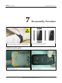
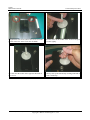
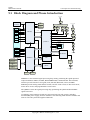
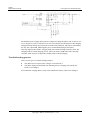
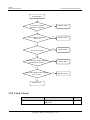
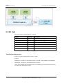
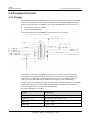
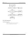
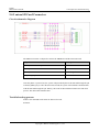
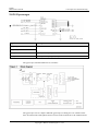
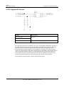
1
U8860 Maintenance Manual Issue 1.0 Date 2011-11-14 HUAWEI TECHNOLOGIES CO., LTD. Copyright © Huawei Technologies Co., Ltd. 2011. All rights reserved. No part of this document may be reproduced or transmitted in any form or by any means without prior written consent of Huawei Technologies Co., Ltd. Trademarks and Permissions and other Huawei trademarks are trademarks of Huawei Technologies Co., Ltd. All other trademarks and trade names mentioned in this document are the property of their respective holders. Notice The purchased products, services and features are stipulated by the contract made between Huawei and the customer. All or part of the products, services and features described in this document may not be within the purchase scope or the usage scope. Unless otherwise specified in the contract, all statements, information, and recommendations in this document are provided "AS IS" without warranties, guarantees or representations of any kind, either express or implied. The information in this document is subject to change without notice. Every effort has been made in the preparation of this document to ensure accuracy of the contents, but all statements, information, and recommendations in this document do not constitute a warranty of any kind, express or implied. Huawei Technologies Co., Ltd. Address: Huawei Industrial Base Bantian, Longgang Shenzhen 518129 People's Republic of China Website: http://www.huawei.com Email: [email protected] Issue 1.0 (2011-11-14) Huawei Proprietary and Confidential Copyright © Huawei Technologies Co., Ltd i U8860 Maintenance Manual About This Document About This Document Author Prepared by R&D Date 2011-11-12 Reviewed by Maintenance support engineer Date 2011-11-14 Approved by Service representative Date 2011-11-14 Change History Date Version Change Reason 2011-11-12 V1.0 Released the first issue. Issue 1.0 (2011-11-14) Revised Chapter Description Huawei Proprietary and Confidential Copyright © Huawei Technologies Co., Ltd Author R&D ii U8860 Maintenance Manual Contents Contents About This Document .................................................................................................................... ii 1 Product Introduction .................................................................................................................... 1 1.1 Appearance ....................................................................................................................................................... 1 1.2 Specifications ................................................................................................................................................... 1 2 Applicable Scope and Precautions ............................................................................................ 4 2.1 Applicable Scope .............................................................................................................................................. 4 2.2 Maintenance Precautions .................................................................................................................................. 4 2.3 How to Obtain Product and Maintenance Information .................................................................................... 4 3 Explosive View .............................................................................................................................. 5 4 Components on PCBA.................................................................................................................. 7 5 Software Upgrade ....................................................................................................................... 13 5.1 Upgrade Preparation....................................................................................................................................... 13 5.2 Normal Upgrade ............................................................................................................................................. 13 5.3 Troubleshooting.............................................................................................................................................. 14 6 Maintenance Tools ...................................................................................................................... 15 7 Disassembly Procedure .............................................................................................................. 17 8 Assembly Procedure ................................................................................................................... 25 9 Principles and Troubleshooting ............................................................................................... 28 9.1 Block Diagram and Phone Introduction ......................................................................................................... 29 9.2 Baseband Unit ................................................................................................................................................ 33 9.2.1 Power-on Management Circuits ............................................................................................................ 33 9.2.2 Charging Management Circuits ............................................................................................................ 37 9.2.3 Clock Circuit ......................................................................................................................................... 39 9.2.4 Flash Memory Circuit ........................................................................................................................... 40 9.3 RF Unit ........................................................................................................................................................... 41 9.4 Peripheral Circuits .......................................................................................................................................... 44 9.4.1 Display .................................................................................................................................................. 44 9.4.2 Keypads ................................................................................................................................................ 46 9.4.3 Vibration ............................................................................................................................................... 48 Issue 1.0 (2011-11-14) Huawei Proprietary and Confidential Copyright © Huawei Technologies Co., Ltd iii U8860 Maintenance Manual Contents 9.4.4 Call Reception ....................................................................................................................................... 49 9.4.5 Call Transmission.................................................................................................................................. 50 9.4.6 Headphone ............................................................................................................................................ 52 9.4.7 SIM Card............................................................................................................................................... 54 9.4.8 I/O Connector........................................................................................................................................ 56 9.4.9 microSD Card Connector ...................................................................................................................... 57 9.4.10 Camera ................................................................................................................................................ 58 9.4.11 BT&WiFi ............................................................................................................................................ 61 9.4.12 Accelerometer ..................................................................................................................................... 64 9.4.13 Compass .............................................................................................................................................. 66 9.4.14 Gyroscope ........................................................................................................................................... 68 9.4.15 Touch Panel ......................................................................................................................................... 69 9.4.16 Approach Sensor ................................................................................................................................. 72 10 Solder Points on the PCB and BGA Chip............................................................................. 75 11 Functional Tests......................................................................................................................... 80 11.1 Keys.............................................................................................................................................................. 80 11.2 MMI Test ...................................................................................................................................................... 81 11.3 Voice Call Test .............................................................................................................................................. 83 Issue 1.0 (2011-11-14) Huawei Proprietary and Confidential Copyright © Huawei Technologies Co., Ltd iv U8860 Maintenance Manual 1 Product Introduction 1 Product Introduction 1.1 Appearance 1.2 Specifications Item Descriptions Dimensions (H x W x D) 122 mm x 61.5 mm x 10.9 mm Issue 1.0 (2011-11-14) Huawei Proprietary and Confidential Copyright © Huawei Technologies Co., Ltd 1 U8860 Maintenance Manual 1 Product Introduction Item Descriptions Technical standard WCDMA/HSDPA/HSUPA: 3GPP FDD Release 7 Band WCDMA: 2100 MHz/900 MHz GSM: 850 MHz/900 MHz/1800 MHz/1900 MHz Weight About 140 g with battery Appearance Bar Antenna Built-in SIM/USIM Standard 6-pin SIM card, supporting 1.8 /3 V USIM card Charger 5 V, 1 A Battery 1930 mAh standby time: 380 hours (3G) Talk time: 400 minutes (3G) Camera Display Connectors Primary Camera 8 MP AF HD Secondary camera 0.3 MP FF Resolution 854 x 480 (FWVGA) Type TFT-LCD Color 16 M Size 4.0 inch Charger port Micro-USB connector USB port Micro-USB connector MicroSD MicroSD card (up to 32 GB) Headphone jack 3.5 mm Bluetooth V2.1 + EDR WiFi 802.11 b/g/n, supporting WiFi USB USB 2.0,480 Mbit/s FM radio Built-in FM radio GPS GPS/AGPS/GPS XTRA Storage space ROM: 4 GB (the available space is about 2.5 GB); RAM: 512 MB (the available space is about 300 MB) Maximum transmit power WCDMA 2100 MHz/900 MHz: +24 dBm (Power Class 3) GSM 850 MHz/900 MHz: +32.5 dBm (Power Class 4) GSM 1800 MHz/1900 MHz: +29.5 dBm (Power Class 1) EDGE 850 MHz/900 MHz: 26 dBm(+/-3 dBm) EDGE 1800 MHz/1900 MHz: 25 dBm(+/-3 dBm) Issue 1.0 (2011-11-14) Huawei Proprietary and Confidential Copyright © Huawei Technologies Co., Ltd 2 U8860 Maintenance Manual 1 Product Introduction Item Descriptions Static sensitivity WCDMA 900 MHz: better than -103.7 dBm/3.84 MHz WCDMA 2100 MHz: better than-106 dBm/3.84 MHz GSM 850 MHz: better than -102 dBm/200 KHz GSM 900 MHz: better than -102 dBm/200 KHz DCS 1800 MHz: better than -102 dBm/200 KHz PCS 1900 MHz: better than -102 dBm/200 KHz Temperature Operating temperature: –10 °C to 45 °C (without charger) Storage temperature: –40°C to 70°C Humidity Issue 1.0 (2011-11-14) Operating humidity: 5% to 95% RH Huawei Proprietary and Confidential Copyright © Huawei Technologies Co., Ltd 3 U8860 Maintenance Manual 2 Applicable Scope and Precautions 2 Applicable Scope and Precautions 2.1 Applicable Scope This document provides maintenance instructions for technicians at service centers authorized by Huawei. This service manual is confidential and can be accessed by authorized service sites or companies only. Although every effort has been made to ensure the accuracy of the document, errors may still exist. If you find any error or have any suggestions, please contact Huawei's customer service center. 2.2 Maintenance Precautions Only qualified technicians are allowed to perform the repair and calibration. Perform all operations in electrostatic discharge (ESD) rooms and wear electrostatic wrist straps throughout the operations. Ensure that all the components, screws, and insulators are properly installed after repair and calibration. Ensure that all cables and wires are installed and connected correctly. Ensure that the soldering is pb-free and compliant with the environmental-friendly requirements. ESD is the major cause of damages to electrostatic-sensitive components, so every service center must pay high attention to avoid ESD discharge and comply with the ESD protection requirements of this manual. 2.3 How to Obtain Product and Maintenance Information To obtain relevant product and maintenance information, you can visit Huawei website at http://www.huaweidevice.com/cn/technicaIndex.do Issue 1.0 (2011-11-14) Huawei Proprietary and Confidential Copyright © Huawei Technologies Co., Ltd 4 U8860 Maintenance Manual 3 Explosive View 3 Explosive View List of components in the explosive view drawing Note: The components listed in the following table are structural parts of the phone, and cannot be used as reference when applying for spare parts. No. Description Quantity 1 U8860 touch panel protective film 1 2 U8860 touch panel 1 3 U8860 receiver decorating items 1 Issue 1.0 (2011-11-14) Huawei Proprietary and Confidential Copyright © Huawei Technologies Co., Ltd 5 U8860 Maintenance Manual 3 Explosive View No. Description Quantity 4 U8860 cover A assembly 1 5 U8860 main FPC 1 6 U8860 receiver 1 7 U8860 front camera 1 8 U8860 main PCB 1 9 U8860 speaker 1 10 U8860 battery 1 11 U8860 battery cover 1 12 U8860 test point protection jacket 1 13 U8860 screws 6 14 U8860 cover B assembly 1 15 U8860 rear camera 1 16 U8860 LCD shielding film 1 17 U8860 microphone 1 18 U8860 LCD module 1 Issue 1.0 (2011-11-14) Huawei Proprietary and Confidential Copyright © Huawei Technologies Co., Ltd 6 U8860 Maintenance Manual 4 Components on PCBA 4 Components on PCBA J1502 IO connector-Mini USB type B socket damage results in charging failure and data communication failure. U1001 headphone jack damage results in charging failure. MIC601 MIC damage results in call transmission failure. X401 crystal oscillator-19.2 MHz damage results in power-on failure. X701 crystal oscillator24.576 MHz damage results in LPA (Low power audio) failure and power-on failure. U4201 Single Band 2.4 GHz WLAN/Bluetooth 2.1/FM single chip -BCM4329 damage results in Bluetooth, WiFi and FM failures. U1701 NAND FLASH4GB EMMC damage results in power-on failure and software failure. U4104 RF switch-0.5~3.0 GHz damage results in Bluetooth and WiFi failures. U4003 LED Driver damage results in LED backlight failure. X4101 crystal oscillator -37.4 MHz damage results in Bluetooth, WiFi and FM failures. U203 Switching Regulators damage results in power-on failure. U6002 RF low noise amplifier damage results in GPS failure. U6001 SAW filter damage results in GPS failure. U4001 WCMDA/GSM dual mode RF transmission and reception(QTR8615) damage results in RF failure and audio failures. X402 crystal oscillator0.032768 MHz damage results in power-on failure. U2001 audio amplifier damage results in audio failure. U5003 SAW filter2140MHz (receive diversity) damage results in weak W2100MHz signal. U301power management chip (PM8058) damage results in power-on failure. J1302 BTB connector damage results in power-on failure, TP failure, motor vibrating failure, speaker soundless, and approach light failure. U5002 RF low noise amplifier (receive diversity) damage results in weak W2100MHz signal. Issue 1.0 (2011-11-14) Huawei Proprietary and Confidential Copyright © Huawei Technologies Co., Ltd 7 U8860 Maintenance Manual 4 Components on PCBA J3201~J3203 master antenna contacts damage results in RF failure. U3201 RF connector damage results in RF failure. U201 WCDMA/GSMdual mode baseband processor MSM8255T damage results in power-on failure, system breakdown, and RF failure. U3501 RF power module and GSM PA damage results in GSM transmission failure and GSM no registration. J1201 FPC connector damage results in display failure. U3302 RF power module -1920~1980 MHz damage results in W2100 MHz transmission failure. U3202 RF switch damage results in RF failure. U3301 SAW filter1950 MHz damage results in W2100 MHz transmission failure. Z4201 ceramic filter damage results in Bluetooth and WiFi damage. U3404 duplexer- TX: 880~915MHz/RX:925 ~960MHz damage results in W900 MHz transmission and reception failure. J1602 MicroSD card holder damage results in microSD card failure. U3402 RF power failure -880 MHz ~ 915 MHz damage results in W900 MHz transmission failure. U1401 semiconductor sensorAccelerometer -LGA3 axis damages result in gravity sensing failure. U1402 semiconductor sensor-electronic compass damages result in compass failure. U2101 semiconductor sensor-3 axis gyroscopes damages result in degree rotation sensing failure. J6003 RF connector damage results in GPS failure. J1902 BTB connector and primary camera interface damages result in primary camera failure. U3900 Switching Regulators damage results in power-on failure. J1501 card holder connector-battery socket-3PIN damage results in power-on failure. J1601 SIM card holder damage results in SIM card failure. U3304 duplexer - RX: 2110~2170 MHz/TX: 1920~1980 MHz1.9dB failure results in W2100 MHz transmission and reception failure. U1102 LED flash driver IC damage results in camera flash failure. J1301 headphone connector - 3.5 mm damage results in headphone failure. MIC2001 microphone damage results in low or noisy transmitted voice. J1901BTB connector and front camera damages result in front camera failure. Issue 1.0 (2011-11-14) Huawei Proprietary and Confidential Copyright © Huawei Technologies Co., Ltd 8 U8860 Maintenance Manual 4 Components on PCBA Approach light sensor damage results in ambient light and approach light sensing failure. Power key damage results in power-on failure. BTB connector damage results in power-on failure, TP failure, motor vibrating failure, speaker soundless, and approach light failure. Volume key damage results that volume cannot be adjusted by pressing volume key. Flash damage results in flash function failure. Motor damage results in vibration failure. TP BTB connector damage results in touch panel failure. Speaker connection point damage results in speaker failure. BOM Code Description Bit 15040208 Transient voltage suppression diode-6.8 V-11.4 V-75 W-7 A-SOT-363 D1301, D1601 15040238 Transient voltage suppression diode-6 V-14 V-10 W-12 A-SOD882/0402 D1501 Issue 1.0 (2011-11-14) Huawei Proprietary and Confidential Copyright © Huawei Technologies Co., Ltd 9 U8860 Maintenance Manual 4 Components on PCBA BOM Code Description Bit 15020099 Lighting diode-0.045 cd-White-25 mA-0603, SMD D1502, D1503, D1504, D1505 15010251 Schottky diode-30 V-0.2 A-0.5 V-SOD523 D2001, D4001 19040121 Fast Blowout Fuse-32 V-2 A-IEC Spec-0.03 ohm-0.100 A*A*Sec-UL/CSA/ANSI 248 Certificated F1501 14090079 FPC connector -27pin-0.6 mm-0.3 mm-horizontal-0.2 mm J1201 14240246 Headphone Connector, 3.5 mm, 6 pin, Side plugging, SMT, Mid Mount, 1.85 mm Height from PCB Top Side, Arc type J1301 14240100 Card holder connector—battery socket-3PIN-side contact-2.8 mm-1.4 mm-with positioning peg J1501 14240272 IO connector-Micro_B-Female-5pin-bend-SMT J1502 14240207 Card holder connector-SIM card socket-6 Pin-horizontal-2.54 mm-without clip-without positioning peg-SMT-spherical structure-height-2.0 mm J1601 14240243 Card holder connector-Micro SD Receptacle-10 Pin-bend-1.1 mm-without clip-without positioning peg J1602 14240181 BTB connector-female-24-0.4 mm-1 mm-SMT J1302, J1901, J1902 13010265 SAW filter -1574.42 MHz/1605.89 MHz-2.2 dB-50 V-1411-Balance J4105 14240004 RF connector-straight-female-SMT J6003, U3201 22050053 Microphone-44 dB.-D4.0 mm*1.3 mm-SMT MIC2001, MIC601 15060150 MOSFET-P channel—12 V-2.4 A-0.112 ohm-8 V-SOT-23 Q301 15050170 Triode-NPN bias resistor transistor Q1501 07050063 NTC-150000 ohms-SMT-0402 RT301 07040061 Varistor-12 V-99999 V-5A-25V-SMT-0402-50pF@1 KHz RV1501, RV2001, RV2002, RV2003, RV2004 07040071 Varistor-90 V-45 V-1 A-300 V-SMT-0402-3pF@100 MHz RV1502, RV1503 07040075 Varistor-18 V-14 V-10 A-40 V-SMT-0402-82pF@1 KHz RV1504 39200306 CPU-WCDMA/GSM dual mode baseband processor MSM8255T U201 39110566 Switching Regulators-1~4 V-1.5 A-SMT U203, U3900 39200177 Terminal Dedicated IC, Power Management IC of QUALCOMM MSM7x30 Series (PM8058) U301 39110531 DCDC charging control chip-20-Pin WCSP U1001 39110523 LED flash driver IC-QFN16 U1102 Issue 1.0 (2011-11-14) Huawei Proprietary and Confidential Copyright © Huawei Technologies Co., Ltd 10 U8860 Maintenance Manual 4 Components on PCBA BOM Code Description Bit 38140023 Semiconductor sensor-accelerometer -LGA-3 axis U1401 38140024 Semiconductor sensor – Electronic compass-WL-CSP (pb-free)-3 axis U1402 40060276 NAND FLASH-4GB EMMC V4.4-52 MHz-1024 KB U1701 39080127 Audio amplifier --2.5 V~5.5 V-differential-Micro SMD 9pin (pb free BGA) U2001 38020046 Analog switch-DUAL SPDT-2.7-4.2V-0.6 ohm-16 MHz-QFN10L U2002 38140020 Semiconductor sensor—3 axis gyroscope-SMT U2101 47140073 RF switch -824-2170 MHz U3202 13010147 SAW filter-881.5 MHz-2.2 dB-50 V-00241564 U3203 13010186 SAW filter – 1950 MHz-2.9-QCS5I U3301 47100397 RF power module-1920~1980 MHz-28.2 dB-3*3 QFN-1000 V U3302 13080038 Duplexer-RX: 2110~2170 MHz/TX: 1920~1980 MHz U3304 13010189 SAW filter-897.5 MHz-2.7 dB-100V(MM)-SFLT5-0101 U3401 47100387 RF power module-880 MHz~915 MHz-28/18/11-QFN-1000 V U3402 13080067 Duplexer-TX: 880~915 MHz/RX: 925~960 MHz U3404 47100307 RF power module-824-849 MHz; 880-915 MHz; 1710-1785 MHz; 1850-1910 MHz U3501 39110552 Switching Regulators-0.4~3.4 V- U3800 39200249 Terminal dedicated baseband IC-WCMDA/GSM Radio Transceiver (QTR8615) U4001 39110626 Switching Regulators- LED Driver U4003 47140049 RF switch U4104 39200222 Single Band 2.4 GHz WLAN/Bluetooth 2.1/FM single chip-BCM4329-2.3~5.5 V-WLBGA182 (pb free) U4201 47090037 RF low-noise amplifier-1.5 G-3 GHz-15 dB-1.1 dB-QFN-200 V U5002 13010176 SAW filter-2140 MHz-1.9 dB-1.4*1.1 mm U5003 13010264 SAW filter-1590.16 MHz-1.8 dB-50 V-1411 U6001 47090042 RF low-noise amplifier-0.5~3 GHz-16.8 dB-0.87-QFN-250 V U6002 12020141 Crystal oscillator-19.2 MHz-7pF-+/-10 ppm-70 ohm-3.2*2.5*0.6 mm X401 12020125 Crystal oscillator-0.032768 MHz X402 12020162 Crystal oscillator-24.576 MHz-12 pF-+/-30 ppm-100 ohm-3225 X701 Issue 1.0 (2011-11-14) Huawei Proprietary and Confidential Copyright © Huawei Technologies Co., Ltd 11 U8860 Maintenance Manual 4 Components on PCBA BOM Code Description Bit 12020168 Crystal oscillator -37.4 MHz-10pF-+/-10 ppm-80 ohm-2016 X4101 07040064 Varistor—8 V-4 V-30 V-SMT-0405-ESD + EMI component Z1301 13030048 Ceramic filter-2450 MHz-2.9 dB-2.0*1.25*1.05 mm Z4201 13010148 SAW filter-2140 MHz-50 V-00231804 Z5001 40020162 SDRAM-4Gb LPDDR2-333 MHz-32 bit-1.8 V-240 Ball U201_POP Issue 1.0 (2011-11-14) Huawei Proprietary and Confidential Copyright © Huawei Technologies Co., Ltd 12 U8860 Maintenance Manual 5 Software Upgrade 5 Software Upgrade 5.1 Upgrade Preparation Category Contents Remarks Upgrade environment Computer To copy upgrade software MicroSD card More than 512 M Battery With at least 30% power remaining. Main upgrade pack dload/UPDATE.APP Vendor upgrade pack vendor_XXX_XXX/UPDATE.APP Upgrade using SD cards Normal upgrade Upgrade file Upgrade method Forcible upgrade 5.2 Normal Upgrade Step 1 Format the microSD card. Step 2 Create a folder named dload in the root directory of the microSD card. Step 3 Copy the upgrade file to the dload folder. Step 4 Install the microSD card to the phone. Power the phone on, and enter *#*#2846579#*#* in the idle screen. Select SD card upgrade then press Confirm to start the upgrade. Step 5 Before the upgrade, NV items backup is performed (if the phone has not been backed up before). Then the phone restarts and the upgrade starts. Step 6 The upgrade progress is displayed on the LCD. Issue 1.0 (2011-11-14) Huawei Proprietary and Confidential Copyright © Huawei Technologies Co., Ltd 13 U8860 Maintenance Manual 5 Software Upgrade Step 7 After the upgrade is completed, the phone restarts and the NV items are restored. Step 8 After the main upgrade pack is upgraded, upgrade the vendor upgrade pack using the same upgrade methods. ----End If the phone cannot be properly powered on, follow the following two methods to forcibly upgrade the phone. Install the battery to the phone (if the screen is splashing, remove the battery and wait for five seconds before installing the battery again). Press Volume + and Volume –, and press Power key, the phone will start SD forcible upgrade. The specific download process is similar to the project menu download. When the phone is not installed with a battery. Press Volume + and Volume –, and connect the phone to a charger, the phone can also start the SD forcible upgrade. It is recommended that you use charger to perform forcible upgrade. If the download still fails, replace the SD card and try forcible upgrade again. 5.3 Troubleshooting Failure Solution Failed to upgrade the phone using the microSD card. 1. Check whether the upgrade file is correct. 2. Check whether the upgrade method is correct. 3. Check whether the microSD functions properly. 4. Perform the upgrade again. Issue 1.0 (2011-11-14) Huawei Proprietary and Confidential Copyright © Huawei Technologies Co., Ltd 14 U8860 Maintenance Manual 6 Maintenance Tools 6 Maintenance Tools Name: constant-temperature heat gun Usage: to heat components Name: constant-temperature heat gun Usage: to heat components Name: soldering iron Usage: to maintain and solder components Name: DC regulated power supply Usage: to supply DC current Name: soldering table Usage: to secure the main PCBA Issue 1.0 (2011-11-14) Huawei Proprietary and Confidential Copyright © Huawei Technologies Co., Ltd 15 U8860 Maintenance Manual 6 Maintenance Tools Name: pb-free solder wire Usage: soldering Name: digital multimeter Usage: to measure during repair Name: toolkit Usage: to assemble and disassemble components Name: electric screwdriver Usage: to fasten and remove screws Issue 1.0 (2011-11-14) Huawei Proprietary and Confidential Copyright © Huawei Technologies Co., Ltd 16 U8860 Maintenance Manual 7 Disassembly Procedure 7 1. Ensure that the ESD wrist strap is well grounded Disassembly Procedure 2. Start to disassemble the U8860. U8860 disassembly guide: 1. Remove the battery cover. Issue 1.0 (2011-11-14) 2. Remove the battery. Huawei Proprietary and Confidential Copyright © Huawei Technologies Co., Ltd 17 U8860 Maintenance Manual 7 Disassembly Procedure 3. Remove the six screws from cover B. 5. Turn over the buckle in the ZIF interface. Issue 1.0 (2011-11-14) 4. Use a cover opener to loosen the buckle between cover A and cover B. 6. Carefully take out the FPC cable. Huawei Proprietary and Confidential Copyright © Huawei Technologies Co., Ltd 18 U8860 Maintenance Manual 7 Disassembly Procedure 7. Separate the FPC and the main board (Note: there is double-sided tape between FPC and shielding cover, carefully perform the operation to avoid damaging the FPC) 9. Loosen the BTB connector. Issue 1.0 (2011-11-14) 8. Turn over the main board and loosen the BTB connector. 10. Carefully separate the FPC and cover B (Note: there is double-sided tape between the FPC and shielding cover, carefully perform the operation to avoid damaging the FPC). Huawei Proprietary and Confidential Copyright © Huawei Technologies Co., Ltd 19 U8860 Maintenance Manual 7 Disassembly Procedure 11. Remove the receiver. 12. Remove the speaker. 13. The phone is now disassembled. Disassembly guide to touch panel and LCD: Screw for fixing Sucker Cover for fixing Base Level the main FPC separate the TP BTB 2. Disassemble the phone and separate the components from the front cover. The main FPC does not have to be separated. 1. Introduction to the disassembly tools Issue 1.0 (2011-11-14) 3. Separate the BTB that the touch panel connects to main FPC, and lever the part of the main FPC that blocks the TP BTB. Huawei Proprietary and Confidential Copyright © Huawei Technologies Co., Ltd 20 U8860 Maintenance Manual 7 Disassembly Procedure 4-1. Note: Do not press LCD FPC. 4. Put the front cover components into the jig base. The placing direction is as shown in this Figure (See procedure 4-1 and 4-2 for precautions). 4-2. Note: Do not press TP BTB. 5. Fasten the cover. Issue 1.0 (2011-11-14) Huawei Proprietary and Confidential Copyright © Huawei Technologies Co., Ltd 21 U8860 Maintenance Manual 7 Disassembly Procedure 6. Tighten the two screws (Note: The screws lie in the position where the sucker sucks the TP BTB). 7. Put the sucker in the middle of the TP Icon and press the sucker tightly. 7-1. Note: Put the sucker in the opposite direction of the receiver. 8. Slowly suck up the TP and stop sucking until half of the TP is sucked up. Issue 1.0 (2011-11-14) Huawei Proprietary and Confidential Copyright © Huawei Technologies Co., Ltd 22 U8860 Maintenance Manual 7 Disassembly Procedure 8-1. Note: Slowly suck the TP because the FPC of the TP BTB will be broken if the TP is sucked up too fast. 9. Remove the sucker. Note: the TP will easily be removed by opening the sucker edge with your finger nail and letting the air in. 10. Unfasten the screw and gently remove the cover. 11-1. Take out the component and remove the TP gently. Issue 1.0 (2011-11-14) Huawei Proprietary and Confidential Copyright © Huawei Technologies Co., Ltd 23 U8860 Maintenance Manual 7 Disassembly Procedure 11-2. Take out the component and remove the TP gently. 12-1. After removing the TP, use a tweezers to lift the four buckles of the LCD front cover (one of the buckles lies under the side key FPC). Usually after removing three buckles, the LCD can be removed (see Figure 12-2 for precautions). 12-2. Note: the LCD glass is thin and easy to be broken. During disassembly, place the tweezers against 13. Remove the LCD. The disassembly is completed. the buckle instead of the glass. The LCD must not be distorted. Issue 1.0 (2011-11-14) Huawei Proprietary and Confidential Copyright © Huawei Technologies Co., Ltd 24 U8860 Maintenance Manual 8 Assembly Procedure 8 1. Ensure that the ESD wrist strap is well grounded. 3. Install the speaker. Issue 1.0 (2011-11-14) Assembly Procedure 2. Start to assemble the U8860. 4. Install the receiver. Huawei Proprietary and Confidential Copyright © Huawei Technologies Co., Ltd 25 U8860 Maintenance Manual 8 Assembly Procedure 5. Install the FPC and ensure that the FPC aligns the positioning rod. 6. Connect the BTB connector. 7. Connect the BTB connector. 8. Install the main board. 9. Paste the FPC on the main board and ensure that the FPC aligns the positioning hole. 10. Insert the FPC into the ZIF interface. Issue 1.0 (2011-11-14) Huawei Proprietary and Confidential Copyright © Huawei Technologies Co., Ltd 26 U8860 Maintenance Manual 8 Assembly Procedure 11. Clip the buckle of the ZIF interface. 12. Install cover B. 13. Install the six crews in cover B. 14. Install battery. 15. Install battery cover. Issue 1.0 (2011-11-14) 16. The U8860 is now assembled. Huawei Proprietary and Confidential Copyright © Huawei Technologies Co., Ltd 27 U8860 Maintenance Manual 9 Principles and Troubleshooting 9 Principles and Troubleshooting Before repairing a phone, ensure that the failure of the phone is not caused by environmental factors or incorrect functional settings, it is recommended that you restore the phone to its factory defaults. Issue 1.0 (2011-11-14) Huawei Proprietary and Confidential Copyright © Huawei Technologies Co., Ltd 28 U8860 Maintenance Manual 9 Principles and Troubleshooting 9.1 Block Diagram and Phone Introduction Main Antenna Connector EXTERNAL CHARGER 32.8 KHz POWER Diversity Antenna Antenna switch 19.2MHz OPT Interface Matching Matching Duplexer Duplexer GPA Matching WPA Connector VBAT CHARGE SIDE KEY Power PM8058 GSM SAW PWR KEY SAW USIM UMTS KEY BACK LIGHT LNA Control GPIO Matching STATUS INDICATOR FLASH QTR8615 Interface Power Filter MIC*2 Power SPEAKER LNA RCVER TF CARD IQ & control VIBRATOR Filter WIFI BT FM CAMERA*2 IQ & control LCD BCM4329 TP GPS Antenna Power USB MSM8255 G SENSOR Bus POP GYROSCOPE Antenna switch PROXIMITY AMBIENT IIC Bus NFC SDC2 Bus eMMC SAW AMBIENT COMPASS WLAN&BT Antenna JTAG MODE OPTION MSM8255 is the baseband signal processing chip, mainly performing the signal input and output of IMAGE, VIDEO, AUDIO, RF INTERFACES, CONECTIVITY. The baseband interface provides interfaces of keypad, LCD, SD card, Bluetooth, camera, and MIC. PM8058 provides analog multi-channel switch, real-time clock circuit, TCXO clock circuit, motor driver circuit, and programmable current source. The QTR8615 is the RF signal processing chip, performing the uplink and downlink RF signal conversion. According to logic functions, boards are categorized into four sub-systems, including baseband, RF, power supply, and user interfaces. The following table describes modules and units of each sub-system and supported functions. Issue 1.0 (2011-11-14) Huawei Proprietary and Confidential Copyright © Huawei Technologies Co., Ltd 29 U8860 Maintenance Manual 9 Principles and Troubleshooting Subsystem Module Unit Function Baseband subsystem MSM8255 Modem subsystem As a MODEM processor, the ARM11 is 400 MHz, performing the modulation and demodulation of WCDMA, GPS, and GSM. The subsystem includes ARM11 processor, modem DSP, modem AHB bus, interruption controller, and sleep controller. Application subsystem The Scorpion processor is 1400 MHz, supporting function modules such as microSD card, EBI2, UART/USIM, I2C, GPIO, and clock. The subsystem includes ARM11 processor, application DSP, and dedicated data mover. User interface processing unit Camera interface, PCM interface, broadband CODEC, Vocoder, RF interface, HKADC, LCD interface, SD interface, USB interface, UART interface, USIM card interface, SBI interface, GPIO, JTAG/ETM interface, and keypad interface Multimedia and game engine The multimedia and game engine of the MSM8255 runs Mpeg/jpeg hardware engine and game engine, JAVA accelerator, and provides MP3/MMS/MIDI functions. Power supply voltage monitoring Lists monitoring targets, such as external power input, battery, button battery, VDD-phone, and important LDO. Temperature monitoring Battery temperature, PA temperature, and 19.2 MHz crystal oscillator temperature EMMC EMMC feature, power consumption, file system support Stores programs and NV items, 4 GB DDR2 RAM (POP) Memory RAM for program running, 2 GB (64M×32) Transmission and receiving of WCDMA and GSM/DCS AFC circuit, APC circuit, AGC circuit, each component Performs the RF function of WCDMA receiving and transmission, mainly includes QTR8615 RF chip and its peripheral circuit. GPS GPS receiving Receives and processes GPS signals, mainly including QTR8615 chip and its peripheral circuit. BT interface BT module Transmits and receives the baseband function and RF signal of Bluetooth and WLAN, mainly includes BT + WiFi module and its peripheral circuit WiFi interface WiFi chip Uses BCM4329 chip to perform the WiFi function. Environment monitoring (PM8058) RF subsystem Issue 1.0 (2011-11-14) Huawei Proprietary and Confidential Copyright © Huawei Technologies Co., Ltd 30 U8860 Maintenance Manual Subsystem User interface subsystem 9 Principles and Troubleshooting Module Unit Function Oscillator and frequency synthesizer Use crystal oscillator instead of temperature compensated oscillator Generates highly accurate TCXVCO of 19.2 MHz local reference clock. The QTR8615 embeds LO for WCDMA and GPS. Antenna External antenna, internal interface component, antenna protection The phone provides internal antenna for signal transmission and supports WCDMA high and low frequency band. U8860-92 phone antennas include main antenna, diversity antenna, WiFi/BT antenna, GPS antenna, FM antenna (headphone) Coupler Power coupler Couples part of the output power of WCDMA power amplifier to QTR8615 for power monitoring. The UART1 interface of the MSM8255 subsystem is used for Bluetooth and the UART3 is used for testing. UART interface USB interface Driver, protection circuit, output interface component Indicates the peripheral circuits of USB interface in MSM8255 subsystem, and unit circuits such as protection circuit and interface connectors. It is the major data service channel for the engineering sample, and can be used to debug and test devices during R&D. USIM card interface Power supply, protection circuit, USIM card holder Mainly includes USIM card holder and related connection circuits. Keypad and backlight Keypad driver circuit, external keypad, backlight LED control circuit Supports GPIO for keypad scanning and provides backlight LED. When a key is pressed, the backlight is on. By connecting with PM8058, it provides brightness adjustment function. Color LCD and backlight LCD driver, interface mode, and backlight control The main LCD is of 16 mega colors. The brightness of the LCD backlight can be controlled by users. TEMMC card Power supply, protection circuit, Mainly includes TEMMC card connector and related interface circuits connector Speaker that plays back MIDI Driver mode, connection mode, speaker component The power of the speaker that plays polyphonic ringtones when there is an incoming call can be 500 mW. It has sound frequency function that can play back 20 – 20 KHz ringtones. It can also play mono-audio MP3 files. Receiver Driver mode, connection mode, receiver component Receiver during a call Issue 1.0 (2011-11-14) Huawei Proprietary and Confidential Copyright © Huawei Technologies Co., Ltd 31 U8860 Maintenance Manual Subsystem Power Supply Subsystem 9 Principles and Troubleshooting Module Unit Function MIC Interface circuit, connection mode, MIC component The phone has a dual built-in MIC to eliminate the environment noise. Earphone Earphone, headphone interface circuit, MIC interface circuit The phone provides a headphone jack to output audio or mp3. The MIC on the headphone cable inputs audio. Vibrator interface Driver mode, connection mode, vibrator When there is an incoming call, the vibrator vibrates. NFC I2C interface control Performs approach sensing function Gyroscopes I2C interface control Realizes the sensing of three directions to perform the game function. Compass I2C interface control Senses the magnetic field to help indicate the direction. Accelerometer I2C interface control Acceleration sensing helps perform the game function Internal backup battery Li-ion battery, interface component Li-ion battery with standard output of 3.7 V/1950 mAh. It is required that the charge/discharge lifecycle is over 500 times. The battery should pass the following authentication: GB18287 safety requirements (Li-ion battery) External power supply (travel charger) Adaptor and interface component The charger meets the requirements of China, Europe, the USA, and Australia: 90–240 V, 45–55 Hz, AC input. The model differs with different markets. The output voltage of the charger is 5 ± 0.25 V. The charger must pass CE and CCC authentication. The output current of the charger should be able to charge the battery and support the normal operation of the phone at the same time. The charging current requirement is 1 A. Power distribution network and power management function Power distribution network It includes filter networks and cabling of the power supply. Backup battery management, charge circuit, charge mode, and charge protection It manages battery charging and discharging, overcharging and over-discharging protection. The battery that maintains RTC current can also be charged. Board circuit power management (power-on/off analysis) It mainly indicates LDO, which manages power supply flexibly. Based on protocols and power-save analysis requirements, the board software manages the power supply of unit circuits according to service status to decrease power consumption of devices. A 32.768 KHz sleep clock is provided. Issue 1.0 (2011-11-14) Huawei Proprietary and Confidential Copyright © Huawei Technologies Co., Ltd 32 U8860 Maintenance Manual Subsystem 9 Principles and Troubleshooting Module Unit Function PM8058 enhanced function RTC It has a built-in RTC circuit and uses a sleep clock of 32.768 KHz that provides precise time. HKADC The 12 MPP interfaces can be provided by PM8058 internally. TCXO driver and other controls The PM8058 has a built-in TCXO driver, twochannel analog signals, and two-channel data signal output. UVLO Low-voltage power-off function. When the input voltage is lower than the threshold for a specific period, the phone powers off. WDT reset Supports WDT counter overflow reset function. Over temperature protection When the on-chip junction temperature exceeds 150°C, the phone powers off. Internal driver circuit Provides four LED drivers, one vibrator driver, and one speaker driver. Interruption management PM8058 has a built-in interruption manager to process related interrupted signals. USB driver Supports USB 2.0 and A/B interface type and does not support OTG function. 9.2 Baseband Unit 9.2.1 Power-on Management Circuits Power-on failures are classified into three types: no current, weak current and excessive current. Many failures are caused by abnormal power supply. If these types of failures occur, troubleshoot them according to the circuit fault troubleshooting methods. Troubleshooting Process To troubleshoot the power-on failure, firstly check whether the I/O connector (battery connector) is damaged. If the I/O connector (battery connector) is not damaged, use a DC regulated power supply to supply the phone with power, and test the faulty phone current. The power-on failure may be caused by any of the following conditions: No current (DC power supply) Generally, no current may be caused by any of the three reasons: Issue 1.0 (2011-11-14) − No power supply channel is set up or the components in the power supply channel are damaged or fall-off. − The main components are cold-soldered; therefore, the system does not operate normally. In this case, the current is less than 100 mA. Huawei Proprietary and Confidential Copyright © Huawei Technologies Co., Ltd 33 U8860 Maintenance Manual 9 Principles and Troubleshooting − The relevant circuits of the power key are faulty, which results in power-on failures. Power-on failure-no current Is the battery connector J1501 connected properly? N Replace J1501. Y Is the FPC normal? N Replace the FPC. Y Is the connector J1302 cold-soldered, damaged or distorted? Y Replace J1302. N Re-solder or replace U301. Weak current (DC power supply) Generally, weak current may be caused by any of the two reasons: Issue 1.0 (2011-11-14) − Software faults (Upgrading or reloading the software may solve the problem.) − The PM output circuit is short-circuited. Huawei Proprietary and Confidential Copyright © Huawei Technologies Co., Ltd 34 U8860 Maintenance Manual 9 Principles and Troubleshooting Power-on failure-weak current Y End Is the problem solved after the software is loaded? N Are the X401(19.2MHz) output and X402(32.768KHz) output normal? N Replace the faulty components. Y Are all channels of output voltage of the PM (U301) normal? (refer to the PM voltage output table) N Replace U301. Y Is the problem solved after U1701 is replaced? Y End N Replace U201. PM voltage output table: Signal Reference Value for the Output Voltage Test Point VREG_L3_1P8/3P3 1.8/3.0V C449 VREG_MSM_USB3V3 3.0V C469 VREG_MSM_USB1V8 1.8V C470 VREG_CAM_2P85 2.85V R4411 VREG_MSM_A2_2V05 2.85V C456 Issue 1.0 (2011-11-14) Huawei Proprietary and Confidential Copyright © Huawei Technologies Co., Ltd 35 U8860 Maintenance Manual 9 Principles and Troubleshooting Signal Reference Value for the Output Voltage Test Point VREG_L10_2P7 2.7V C457 VREG_L11_1P8 1.8V C458 VREG_L14_2P85 2.85V C473 VREG_MSM_QFUSE_PRG 1.8V C445 VREG_L18_2P2 2.2V C465 VRGE_F6 2.6V C1308 VREG_MSM_L20_1V8 1.8V C441 VREG_MSM_MPLL 1.1V C466 VREG_L24_1P2 1.2V C442 VREG_POP_VDDQ_1P2 1.2V C443 VREG_NCP_1V8 -1.8V C464 VREG_S0_1V1_C1 1.1V C418 VREG_S1_1V1_C2 1.1V C450 VREG_S2_1V35_A1 1.3V C447 VREG_S3_1V8 1.8V C424 VREG_S4_2V2 2.2V C426 Excessive current (DC power supply) There are two types of excessive currents: − Excessive current occurs after the Power key is pressed. − The phone has current (greater than 1 mA) when it has been powered off. Excessive current is caused by short circuits. The main reason is ground short circuits of VBAT. Issue 1.0 (2011-11-14) Huawei Proprietary and Confidential Copyright © Huawei Technologies Co., Ltd 36 U8860 Maintenance Manual 9 Principles and Troubleshooting Power-on failure-excessive current N Check the VPH_PWR circuit and the PM output circuit. Y Replace the faulty components. Is the VBAT ground short-circuited? Y Is problem solved after the RF PA (U3402/U3803/U3501) is removed successively? N Y Are the circuit of the battery connection components short-circuited? Replace the faulty components. N Replace U301. 9.2.2 Charging Management Circuits Circuit schematic diagram The power supply of MSM8255 supports two external charging modes: charger mode and USB mode. The schematic diagram is shown as follows: Issue 1.0 (2011-11-14) Huawei Proprietary and Confidential Copyright © Huawei Technologies Co., Ltd 37 U8860 Maintenance Manual 9 Principles and Troubleshooting The dedicated power supply chip bq24152 is adopted to charge the phone with 1A power. The I2C is adopted to perform communication and control GPIO149 and GPIO150. The charging management chip obtains power from the VCHAG of the USB port. The chip is controlled by the I2C. The output VPH_PWR supplies power for the PM and charges the battery. This chip supports three modes: charging mode, boost mode and high resistance mode. The charging mode is normal charging process. The boost mode is USB-OTG mode. The high resistance mode is power-saving mode (standby mode) without charging. Troubleshooting process There are two types of common charging failures: The phone has no response after a charger is connected to it. The phone displays an animated icon indicating that it is charging, but actually, the battery is not charged. To troubleshoot charging failure, firstly check whether the battery connector is damaged. Issue 1.0 (2011-11-14) Huawei Proprietary and Confidential Copyright © Huawei Technologies Co., Ltd 38 U8860 Maintenance Manual 9 Principles and Troubleshooting Charging failure Y Is J1502 cold soldered, damaged or distorted? Replace J1502. N Is the voltage of J1502 Pin1 about 5 V? N Replace J1502. Y N Is F1501 connected. Replace F1501. Y Is the Q301 pin voltage Vs (Pin2) approximate to Vd (Pin3). N Replace Q301. Y Is the output voltage of the charging IC 3.7V-4.2V. N Replace U1001. Y Replace U301. 9.2.3 Clock Circuit Clock Effect VCTCXO in 19.2 MHz Supporting master clock for the MSM8255 Issue 1.0 (2011-11-14) Huawei Proprietary and Confidential Copyright © Huawei Technologies Co., Ltd Remarks 39 U8860 Maintenance Manual 9 Principles and Troubleshooting Clock Effect Remarks 32.768 K crystal for platform use MSM8255 sleep clock signal BT&WiFi in 37.4 MHz BCM4329 clock BCM4329 Troubleshooting process Failures: The phone cannot be powered on or frequently freezes. X401's test result shows that X401 has no outputs or its output frequencies are unstable. Solution: Replace X401. Description of the signals in the circuit diagram in this section Signal Description XTAL_19M _OUT Output from the 19.2 MHz main clock XTAL_19M _IN Input to the 19.2 MHz main clock Reference Measurement or Wave Form 9.2.4 Flash Memory Circuit The MSM8255-0 is able to visit the LPDDR2 through two high-speed buses (EBI0/EBI1). The LPDDR2 is connected to the MSM8255-0 in PoP (Package-on-package) mode. Meanwhile, the MSM8255-0 also can visit the external storage eMMC through a low-speed bus (EBI2), as shown in the following figure. Issue 1.0 (2011-11-14) Huawei Proprietary and Confidential Copyright © Huawei Technologies Co., Ltd 40 U8860 Maintenance Manual 9 Principles and Troubleshooting 9.3 RF Unit The power supplies of the RF unit are as follows: Signal Voltage Description VREG_S2_1V35_A1 1.3 V Supplies power for QTR8615 VREG_S4_2V2 2.2 V Supplies power for QTR8615 VREG_S3_1V8 1.8 V Supplies power for QTR8615 VBAT 3.7 V Supplies 3.7 V voltage for WiFi and BT VREG_L14_2P85 2.85 V Single pole, 10 throw power switch VCC2 3.4 V PA VCC2 Troubleshooting process: Failure: The phone cannot initiate a call or be called. Solution: Maintenance procedure for transmission failure in W2100, W900, GSM900, and GSM1800 Maintenance procedure for transmission failure in W2100: Firstly, ensure that the SIM card and antenna are installed properly, and then detect the phone according to the following procedure. Issue 1.0 (2011-11-14) Huawei Proprietary and Confidential Copyright © Huawei Technologies Co., Ltd 41 U8860 Maintenance Manual 9 Principles and Troubleshooting The transmission channel in W2100 is faulty. Are U3201 Pin 1 and Pin 2 connected when the RF cable is not connecting? N Check U3201. Y Is U3202's switch control signal is normal? (The truth table is the note table 1.) N Check U3201 and U201. Y Is U3302’s PA output in W2100 normal? N Check U3402. Y Is U4001’s Y IQ signal normal? Is the power voltage normal? N Check U4001. Y Check U201. In W900, just replace the U3302 detection with U3402 detection. In GSM900 and GSM1800, just replace the U3302 detection with U3502 detection. Maintenance procedure for reception failure in W2100: Issue 1.0 (2011-11-14) Huawei Proprietary and Confidential Copyright © Huawei Technologies Co., Ltd 42 U8860 Maintenance Manual 9 Principles and Troubleshooting The reception channel in W2100 is faulty. N Are U3201 Pin 11 and Pin 8 connected when the RF cable is not connecting? Check U3201. Y N Is U3202's switch control signal normal? (The truth table is the note table 1.) Check U3201 and U201. Y N Are the signals of U3404 Pin 1 and Pin 8 normal (the difference is less than 2.3 db) ? Check U3404. Y N Is U4001’s IQ signal normal? Is the power voltage normal? Check U4001. Y Check U201. Note: Check the control signals of U3202 switch using a multimeter or oscilloscope. The truth table for control signals is as follows: Note table 1: VC1 VC2 VC3 VC4 TRX_W2100 1 0 1 0 TRX_W900 1 1 1 0 GSM900 Rx 1 0 0 0 GSM1800 Rx 0 0 1 0 In W900, just replace the U3404 detection with U3804 detection. In GSM, just replace the U3404 detection with U3304 detection. Issue 1.0 (2011-11-14) Huawei Proprietary and Confidential Copyright © Huawei Technologies Co., Ltd 43 U8860 Maintenance Manual 9 Principles and Troubleshooting 9.4 Peripheral Circuits 9.4.1 Display The MSM8255 employs the MDDI interface to transmit command and data to the LCD. The U8860 uses Toshiba's LCD. The U8860 uses Toshiba's LCD LT040MDT9000. It is a TFT module with a point matrix of 480RGB x 854, supporting MDDI interface. Its features are: 16.7 M colors, TFT-LCD module Display mode: RGB Stripe The schematic diagram of the MSM8255 and LCD interface is as follows: The U8860's LCD employs the MDDI-type2 interface. It requires only two pairs of low voltage differential signal (LVDS) cables and a pair of power cables, and supports 60 Hz refreshment rate. With frame synchronization function, the LCD uses MDP_VSYNC of GPIO_030 as the data transmission synchronization signal to avoid LCD breakage. A diode composes the PWM signal (pull-up) reflected by environment light detection and the PWM signal reflected by LCD's dynamic backlight adjustment function to a signal and performs computation to control the backlight brightness. The signal definitions are as follow: Signal Description VREG_L16_2P8 LCD analog voltage, 2.8 V VREG_L12_1P8 I/O connector digit voltage, 1.8 V MDDI_SP LVDS + signal MDDI_SN LVDS - signal Issue 1.0 (2011-11-14) Huawei Proprietary and Confidential Copyright © Huawei Technologies Co., Ltd 44 U8860 Maintenance Manual 9 Principles and Troubleshooting Signal Description MDDI_DP LVDS + signal MDDI_DN LVDS - signal MDDI_DN_DATA1 MDDI_DATA+ MDDI_DP_DATA1 MDDI_DATA- LCD_RESET LCD power-on reset signal MDP_VSYNC Longitudinal frame synchronization signal LCD_ID0 Supplier ID LED+ The anode of the backlight LED LED- The cathode of the backlight LED The U8860 adopts 4.02 inches LCD. The backlight adopts six serial LED lights, which are controlled by the backlight LED-driving chip RT9293BGJ6. Troubleshooting process Failure: The phone can be powered on, but its LCD is blank. Solutions: 1. If the phone displays a black screen, it may be LCD backlight fault. 2. If it is LCD fault, refer to the following troubleshooting process. Issue 1.0 (2011-11-14) Huawei Proprietary and Confidential Copyright © Huawei Technologies Co., Ltd 45 U8860 Maintenance Manual 9 Principles and Troubleshooting Display failure Is the problem solved after the software is loaded? Y End N Is the connector J1302 cold soldered, damaged or distorted? Y Replace J1201. N Is J1202 Pin2 2.8 V? N Replace U3900. N Is J1201 Pin21 1.8 V? N Replace U301. Y Is the problem solved after the LCD is replaced? Y End N Replace U201. 9.4.2 Keypads The U8860 has seven keys. Four of them are on the touch panel. You can answer a call, hang up a call, view the menu and back the previous operation by touching them. The GPIO_01 Issue 1.0 (2011-11-14) Huawei Proprietary and Confidential Copyright © Huawei Technologies Co., Ltd 46 U8860 Maintenance Manual 9 Principles and Troubleshooting and GPIO_02 on the side of the PM8058 are Volume+ key and Volume- key. The Power key is detected by KYPD_PWR_N on the PM8058 side instead of the scanning mode. The brightness of the keypad's backlight LEDs can be adjusted by KYPD_DRV_N (PM8058), and it is supplied with power by VPH_PWR. The keypad LEDs are the four LEDs on the LCD. Keypad backlight driver Signal Description Remarks VPH_PWR Power supply Backlight power supply KPD_DRV_N Backlight driver pin When the level is low, the four backlight LEDs light. Issue 1.0 (2011-11-14) Huawei Proprietary and Confidential Copyright © Huawei Technologies Co., Ltd 47 U8860 Maintenance Manual 9 Principles and Troubleshooting Troubleshooting process The keypad does not function. Does the keypad FPC have defects, such as damage or fold? Y Replace the FPC. N Does the connector J1302 have defects, such as cold soldered, damaged or distorted? Y Replace J1302. N Replace U301. 9.4.3 Vibration Circuit schematic diagram Analysis The PM VIB_DRV_N controls the vibrator's driving voltage. The VIB_DRV_N controls the motor vibration by setting high level or low level. When the VIB_DRV_N is in low level, the motor vibrates. Issue 1.0 (2011-11-14) Huawei Proprietary and Confidential Copyright © Huawei Technologies Co., Ltd 48 U8860 Maintenance Manual 9 Principles and Troubleshooting Troubleshooting process Failure: The motor fails to vibrate. Solution: Vibration fault Is the motor normal? N Re-solder the motor. Y Does the motor vibrate after the motor’s two ends are added with 3 V power? N Replace the motor. Y Does the keypad FPC have defects, such as damage or fold? Y Replace the FPC. N Replace U301. 9.4.4 Call Reception Troubleshooting process Failure: After a call is established, no sound can be heard or noises are heard. Solution: For audio fault, check whether the phone is set properly. Generally, the reception faults are caused by earpiece fault or poor earpiece contact. Issue 1.0 (2011-11-14) Huawei Proprietary and Confidential Copyright © Huawei Technologies Co., Ltd 49 U8860 Maintenance Manual 9 Principles and Troubleshooting After a call is established, no sound can be heard. Is the volume set normally? N Reset the volume. Y Is the resistance of the receiver 32Ω? N Replace the receiver. N Replace the faulty components. Y Are the components on the reception circuit normal? Y Replace U4001. 9.4.5 Call Transmission Troubleshooting process Failure: No sound is heard by the other party during a call. Solution: Check whether the phone is set properly. Issue 1.0 (2011-11-14) Huawei Proprietary and Confidential Copyright © Huawei Technologies Co., Ltd 50 U8860 Maintenance Manual 9 Principles and Troubleshooting After a call is established, no sound can be heard by the other party. Is the problem solved after the software is loaded? Y End N Is the MSM_MIC_BIAS voltage 1.8 V? N Check U301. Y Is the problem solved after the MIC is replaced. Y End N Are the components on the circuit that between the MIC and U4001 are damaged or short-circuited? Issue 1.0 (2011-11-14) Huawei Proprietary and Confidential Copyright © Huawei Technologies Co., Ltd 51 U8860 Maintenance Manual 9 Principles and Troubleshooting 9.4.6 Headphone Circuit schematic diagram The headphone connect status is identified according to the HS_DETECT_N (GPIO_026). Before connecting the headphone, HS_DETECT_N is pulled up to high level by VREG_MSM_L20_1V8. After connecting the headphone, HS_DETECT_N is dropped down to low level by the resistor R902. The headphone MIC is supplied with power by MIC_BIAS1 (PM8058/HSED_BIAS1), and it is used for headphone answer detection. U8860's headphone is compatible with two line sequences. The iphone's headphone line sequence is compatible by default. Troubleshooting process Failure: Perform the test using a normal headphone, and no sound is heard. Solution: Issue 1.0 (2011-11-14) Huawei Proprietary and Confidential Copyright © Huawei Technologies Co., Ltd 52 U8860 Maintenance Manual 9 Principles and Troubleshooting No sound can be heard from the headphone. Does J1301 have defects, such as cold soldered, damaged or distorted? Y Replace J1301. N Is D1301 short-circuited? (Pin3 and Pin6 is ground.) Y Replace D1301. Y Is J1301 signal HS_DETECT_N (pin4) normal? (headphone disconnected: high level; headphone connected: low level) N Replace U201. Y Are the components on the circuit that between the MIC and U4001 are damaged or short-circuited? Y Replace the faulty components. N Replace U4001. Issue 1.0 (2011-11-14) Huawei Proprietary and Confidential Copyright © Huawei Technologies Co., Ltd 53 U8860 Maintenance Manual 9 Principles and Troubleshooting No sound is picked up or transmitted from the headphone. N Is J1301 normal? Replace J1301. Y N Are the components on the MIC_BIAS1 circuit are damaged or shortcircuited? Is MSM_MIC_BIAS voltage normal? Y N Is there signal is input in MIC2N/MIC2P when speaker? Is the circuit between MIC2N/MIC2P and U4001 short-circuited? Y Re-solder or replace U4001. 9.4.7 SIM Card Circuit schematic diagram Issue 1.0 (2011-11-14) Huawei Proprietary and Confidential Copyright © Huawei Technologies Co., Ltd 54 U8860 Maintenance Manual 9 Principles and Troubleshooting USIM interface of the MSM8255 Signal Description USIM_IO SIM data line USIM_RST SIM reset signal USIM_CLK SIM clock USIM_VCC SIM power supply, 1.8 V/3.0 V After is phone is powered on, it will detect the SIM card. If the SIM card is found, it will start data communication, and the preceding pins will perform power clock and data transmission. If the SIM card is not found, the system does not detect SIM card status. Therefore, it does not support hot swap. Troubleshooting process Failure: The USIM card cannot be detected. Solution: Firstly, check whether the software is faulty or the USIM card is damaged. If the card is not damaged, perform the following procedure. No USIM card is found. Is the USIM card socket normal? Y Is D1601 short-circuited? (Pin3 and Pin6 is ground.) N Re-solder or replace the USIM card socket J1601. Y Replace D1601. N Are the power-supply pin and signal pin normal? N After the cabling problem is excluded, resolder or replace the U301. Y Re-solder or replace the U301. Issue 1.0 (2011-11-14) Huawei Proprietary and Confidential Copyright © Huawei Technologies Co., Ltd 55 U8860 Maintenance Manual 9 Principles and Troubleshooting 9.4.8 I/O Connector Circuit schematic diagram Analysis When a charger connected to the I/O connector (USB connector), the charger provides charging voltage to charge the battery. When the phone is connected to a computer using a USB cable, USB_DM and USB_DP are used for communication (for upgrading the phone's firmware, reading information from the phone…) between the phone and the computer. Troubleshooting process Failure: The phone cannot be charged or detected by a computer. Solution: Clean, re-solder or replace the USB connector. Description of the signals in the circuit diagram in this section Signal Description Reference Measurement or Wave Form VEXT_DC Charging current input High level, 5 V USB_DM Digital signal USB_DP Digital signal Issue 1.0 (2011-11-14) Huawei Proprietary and Confidential Copyright © Huawei Technologies Co., Ltd 56 U8860 Maintenance Manual 9 Principles and Troubleshooting 9.4.9 microSD Card Connector Circuit schematic diagram The SDIO4 connector is adopted to connect the MSM8255 and the T-FLASH card. Signal Description SDC4_DATA0~ SDC4_DATA3 Data line SDC4_CLK Clock SDC4_CMD Control signal SD_PWR_EN_N Presence detection After the phone is powered on, the system will periodically detect the SD card through the pin of the SD_PWR_EN_N. After the SD card is found, the system will establish communication with the SD card through the pin. SDC4_CLK controls SD card data transmission and clock process. The data cable transmits data. Troubleshooting process Failure: The microSD cards cannot be detected or read. Solution: Issue 1.0 (2011-11-14) Huawei Proprietary and Confidential Copyright © Huawei Technologies Co., Ltd 57 U8860 Maintenance Manual 9 Principles and Troubleshooting No SD card is found. N Is the SD card socket normal? Re-solder or replace the SD card socket J1602. Y Is the SD card’s VDD power supply normal? N Is the power supply circuit short-circuited? Y Is the data transmission circuit damaged or short-circuited? 9.4.10 Camera Circuit schematic diagram Issue 1.0 (2011-11-14) Huawei Proprietary and Confidential Copyright © Huawei Technologies Co., Ltd 58 U8860 Maintenance Manual 9 Principles and Troubleshooting The 8-megapixel primary camera uses the 24 pin BTB connector and is controlled by the I2C bus. The data is transmitted in MIPI mode. Signal Remarks VREG_L11_1P8 1.8 V VREG_L11_1P8 1.8 V VREG_CAM_2P85 2.85 V CAMIF_MCLK Camera's reference clock MSM->CAMERA CAMMIPI_PCLK MIPI clock CAMMIPI_NCLK MIPI clock CAM_SHDN_OUTS Close signal SCL_GSB_CAM I2C control signal SDA_GSB_CAM I2C control signal CAMIF_ID Module supplier identification CAMIF_RESET_OUTS_N Reset signal CAM_VCM_PD_N VCM motor control signal VREG_CAM_2P85 VCM motor power supply signal DATA1_P Data communication signal DATA1_N Data communication signal DATA2_P Data communication signal DATA2_N Data communication signal After the camera functions are enabled and the camera is powered on, the system establishes control communication with the camera through the I2C bus to control the camera. The camera communication is implemented depending on the MIPI interface. The data is synchronously provided by two CAMMIPI clocks, and is transmitted by data interface. Issue 1.0 (2011-11-14) Huawei Proprietary and Confidential Copyright © Huawei Technologies Co., Ltd 59 U8860 Maintenance Manual 9 Principles and Troubleshooting During focal length adjustment, the internal motor is supplied with power by VREG_CAM_2P85, and the control signal is provided by CAMIF_RESET_OUTS_N. The 0.3-megapixel secondary camera shares the I2C bus with the 8-megapixel primary camera. The data is transmitted in RAW mode. The interface definitions are as follows: Signal Remarks VREG_L11_1P8 1.8 V VREG_L13_2P85 2.85 V CAMIF_MCLK Camera's reference clock MSM->CAMERA CAMIF_PCLK CAMRA->MSM 96MHz max CAMIF_DATA[11:4] 8-bit USB cable CAMIF_HSYNC Line synchronizing signal CAMIF_VSYNC Frame synchronizing signal SCL_GSB_CAM I2C control signal SDA_GSB_CAM CAMIF_RESET_OUTS_SLAV E Reset signal The function implementation method for the secondary camera is same as that for the primary camera while their data transmission modes are different. Troubleshooting process: Failure: No image can be captured. Solution: Issue 1.0 (2011-11-14) Huawei Proprietary and Confidential Copyright © Huawei Technologies Co., Ltd 60 U8860 Maintenance Manual 9 Principles and Troubleshooting Camera failure Y Is the problem solved after the software is loaded? End N N Is the camera supplied with power normally? Replace U301. Y Does the camera interface (J1902/J1901) have defects, such as cold soldered, damaged or distorted? Y Replace J1902/J1901. N Is the problem solved after the camera is replaced? Y End N Replace U201. 9.4.11 BT&WiFi The BT functions are implemented depending on the BCM4329, and the BT data of the MSM8255 and BCM4329 are transmitted by UART and PCM. The signal definitions are as follows: Signal Remarks QTR_BT_UART_CTS The ready to receive information sent to the Slave by the Host QTR_BT_UART_RTS The clear to send information sent to the Host by the Slave QTR_BT_UART_TXD Sending signal QTR_BT_UART_RXD Receiving signal QTR_BT_PCM_DIN PCM input QTR_BT_PCM_DOUT PCM output Issue 1.0 (2011-11-14) Huawei Proprietary and Confidential Copyright © Huawei Technologies Co., Ltd 61 U8860 Maintenance Manual 9 Principles and Troubleshooting Signal Remarks QTR_BT_PCM_SYNC PCM synchronization QTR_BT_PCM_BCLK PCM clock QTR_BT_HOST_WAKE Waking up the host QTR_BT_EXT_WAKE Waking up the peripherals After the BT module is enabled, you can perform BT communication. You can know whether the host or peripherals is woken up based on QTR_BT_HOST_WAKE or QTR_BT_EXT_WAKE. The signal interfaces of QTR_BT_UART_TXD and QTR_BT_UART_RXD control data transmission, determining to receive or transmit data. QTR_BT_UART_CTS and QTR_BT_UART_RTS transmit status signals, and you can know the BT status according to these two pins. Data transmission is performed by the four pins of PCM. The Wifi functions are implemented depending on the BCM4329, the communication of the MSM8255 and BCM4329 adopts the SDIO bus of the SDIO3 interface. The signal definitions are as follows: Signal Description SDC3_DATA3 Data line SDC3_DATA2 SDC3_DATA1 SDC3_DATA0 SDC3_CLK Clock SDC3_CMD Control signal After the WiFi function is enabled, the data transmission is controlled by SDC3_CLK and SDC3_CMD, and is performed by the four data control pins. Troubleshooting process Failure: the BT and WiFi functions are abnormal. Solution: Issue 1.0 (2011-11-14) Huawei Proprietary and Confidential Copyright © Huawei Technologies Co., Ltd 62 U8860 Maintenance Manual 9 Principles and Troubleshooting The BT&WiFi functions are abnormal. Y Is the problem solved after the software is loaded? End N Y Is the problem solved after the BT antenna and BT antenna spring are reinstalled? End N Is the problem solved after the BT antenna is replaced? Y End N Is the cabling between the antenna and U4201 damaged or short-circuited? Issue 1.0 (2011-11-14) Huawei Proprietary and Confidential Copyright © Huawei Technologies Co., Ltd 63 U8860 Maintenance Manual 9 Principles and Troubleshooting 9.4.12 Accelerometer Circuit schematic diagram Signal Description I2C_SCL_HW I2C bus I2C_SDA_HW ACCE_INT Accelerometer interrupt signal ACCE_INT2 Accelerometer interrupt signal (sleep)—— Issue 1.0 (2011-11-14) Huawei Proprietary and Confidential Copyright © Huawei Technologies Co., Ltd 64 U8860 Maintenance Manual 9 Principles and Troubleshooting Analysis Firstly, the internal micro mechanical structure of the accelerometer detects the accelerometer position. The position is reflected as the three-axis-electric charge amount inside the accelerometer. The voltage conversion device for the internal electric charge converts the voltage to voltage signal and amplifies it. Then the amplified signal is converted to digit signal through the 12-bit ADC, and is transmitted to the chip's DSP for data processing. The interrupt signal and data signal are outputted for data transmission with the main chip. Troubleshooting process: Failure: Relevant functions of the accelerometer are disabled. Solution: Issue 1.0 (2011-11-14) Huawei Proprietary and Confidential Copyright © Huawei Technologies Co., Ltd 65 U8860 Maintenance Manual 9 Principles and Troubleshooting Relevant functions of the accelerometer are disabled. Y Is the problem solved after the software is loaded? End N Y Is the problem solved after the accelerometer is replaced? End N Are the components on the accelerometer’s power supply circuit and control circuit damaged or short-circuited? 9.4.13 Compass Circuit schematic diagram Signal Description I2C_SCL_HW I2C bus Issue 1.0 (2011-11-14) Huawei Proprietary and Confidential Copyright © Huawei Technologies Co., Ltd 66 U8860 Maintenance Manual 9 Principles and Troubleshooting Signal Description I2C_SDA_HW COMPASS_INT Compass interrupt signal The compass is a three-axis-Hall sensor. Because of the earth's magnetic field, the chip generates electricity components on the three axes. After three components are processed inside the chip, the direction of the earth's magnetic field relative to the chip is obtained. Through the I2C bus, the chip communicates with the main chip. Through data processing, the main chip can obtain the relationship of the earth's magnetic field direction and the phone position. When the compass is operating, the compass direction variation is reported to the main chip, but in the map program, the compass direction is related to GPS. As a result, the unstable GPS signal may cause compass direction error. Troubleshooting process: Failure: Relevant functions of the compass are disabled. Solution: The compass direction has a great deviation. Y Is the problem solved after the software is loaded? End N Y Is the problem solved after the sensor is replaced? End N Are the components on the sensor’s power supply circuit and control circuit damaged or short-circuited? Issue 1.0 (2011-11-14) Huawei Proprietary and Confidential Copyright © Huawei Technologies Co., Ltd 67 U8860 Maintenance Manual 9 Principles and Troubleshooting 9.4.14 Gyroscope Signal Description I2C_SCL_HW I2C bus I2C_SDA_HW GYR_INT1 Gyroscope interrupt signal GYR_INT2 Gyroscope interrupt signal (sleep) The gyroscope's internal architecture is as follows: The gyroscope's core is a dipole. When the gyroscope is working, the core vibrates on the three axes' directions. If the phone rotates, because of the Coriolis force, the rotation will be Issue 1.0 (2011-11-14) Huawei Proprietary and Confidential Copyright © Huawei Technologies Co., Ltd 68 U8860 Maintenance Manual 9 Principles and Troubleshooting reflected as the variation of the corresponding electric signal of the internal circuit. After processing the result, you can obtain the rotation direction. Troubleshooting process: Failure: Relevant functions of the gyroscope are disabled. Solution: The gyroscope functions are disabled. Y Is the problem solved after the software is loaded? End N Y Is the problem solved after the gyroscope is replaced? End N Are the components on the gyroscope’s power supply circuit and control circuit damaged or short-circuited? 9.4.15 Touch Panel Issue 1.0 (2011-11-14) Touch panel's circuit unit is a module fixed inside the touch panel. Its interface circuits are as follows: Huawei Proprietary and Confidential Copyright © Huawei Technologies Co., Ltd 69 U8860 Maintenance Manual 9 Principles and Troubleshooting The principle of capacitive touch panel is: Attaching a layer of transparent metal conductive materials on the glass. When the finger touches the touch panel, the capacity on the touching point varies, which causes the oscillator frequency to vary. Then system can obtain the touching position according to the frequency variation. As the touch panel module is integrated on the touch panel, the main board and touch panel must be connected by a BTB connector. The connector can be damaged easily. In addition, you must power on the touch panel according to the power-on sequence. First supply the 2.7 V power, and then supply the 1.8 V power; otherwise, the touch panel is disabled. When the touch panel is operating, the I2C controls data transmission. Four touching key fields are added to the U8860's 4-inch capacitive touch panel, and four backlight LEDs for the four keys are added to the touch panel module. The definitions of the interfaces for touch panel and MSM8255 and touch panel and PM8058 are as follow: Signal Description VREG_L10_2P7 Touch panel analog power supply, 2.7 V VREG_MSM_L20_1V8 Touch panel digit power supply and I/O connector power supply, 1.8 V TOUCH_INT Touch panel interrupt signal I2C_SCL_HW Touch panel' I2C clock cable I2C_SDA_HW Touch panel' I2C data cable TOUCH_RESET Touch panel reset signal Troubleshooting process: Failure: The touch panel is faulty. Solution: Issue 1.0 (2011-11-14) Huawei Proprietary and Confidential Copyright © Huawei Technologies Co., Ltd 70 U8860 Maintenance Manual 9 Principles and Troubleshooting The touch panel functions are disabled. Y Is the problem solved after the software is loaded? End N Y Is the problem solved after the touch panel connector is refastened. End N Is the problem solved after the touch panel connector is replaced. Y End N Is the problem solved after the FPC is replaced. Y End N Are the components on the touch panel’s power supply circuit and control circuit damaged or shortcircuited? Issue 1.0 (2011-11-14) Huawei Proprietary and Confidential Copyright © Huawei Technologies Co., Ltd 71 U8860 Maintenance Manual 9 Principles and Troubleshooting 9.4.16 Approach Sensor Signal Description I2C_SCL_HW I2C bus I2C_SDA_HW PRO_INT Three-in-one interrupt signal The approach sensor has two functions. One is for screen brightness adjustment. The other is for misoperation prevention. If you select automatic adjustment, the system will enable the approach sensor's environment light detection function to detect the brightness of the environment light, and then adjust the screen brightness accordingly. The approach sensor realizes the approach status of the phone and other objects depending on the internal infrared sensor. If the approach status achieves a certain threshold, the system will shut down the screen forcibly to prevent it from misoperation. The I2C bus controls the approach sensor components and data transmission. The interrupt pin provides the interrupt signal. The approach's internal structure is shown in the following figure. Issue 1.0 (2011-11-14) Huawei Proprietary and Confidential Copyright © Huawei Technologies Co., Ltd 72 U8860 Maintenance Manual 9 Principles and Troubleshooting The CH0/CH1 receives environment light and generates environment light value by processing the data internally. Then the system automatically adjusts the LCD brightness according to the environment light value. The approach sensor is to prevent the phone from misoperations caused by the contact of the face and touch panel. As a result, if the inferred emitted by the LED inside the chip is blocked, it will be reflected. Then the sensor will receive the reflected light through the photodiode and identify the obstacle position. When the approach status achieves a certain threshold, the system triggers the operation to shut down the touch panel. Troubleshooting process Failure: The approach sensor is faulty. Solution: Issue 1.0 (2011-11-14) Huawei Proprietary and Confidential Copyright © Huawei Technologies Co., Ltd 73 U8860 Maintenance Manual 9 Principles and Troubleshooting The approach sensor functions are disabled. Y Is the problem solved after the software is loaded? End N Y Is the problem solved after the approach sensor light hole is cleaned? End N Is the problem solved after the approach sensor is replaced? Y End N Y Is the problem solved after the FPC is replaced? End N Are the components on the touch panel’s power supply circuit and control circuit damaged or shortcircuited? Issue 1.0 (2011-11-14) Huawei Proprietary and Confidential Copyright © Huawei Technologies Co., Ltd 74 U8860 Maintenance Manual 10 Solder Points on the PCB and BGA Chip 10 Solder Points on the PCB and BGA Chip Red (R:255,G:0,B:0) Green (R:0,G:255,B:0) :Solder point :Vacant point Main board diagram: Issue 1.0 (2011-11-14) Huawei Proprietary and Confidential Copyright © Huawei Technologies Co., Ltd 75 U8860 Maintenance Manual Issue 1.0 (2011-11-14) 10 Solder Points on the PCB and BGA Chip Huawei Proprietary and Confidential Copyright © Huawei Technologies Co., Ltd 76 U8860 Maintenance Manual Issue 1.0 (2011-11-14) 10 Solder Points on the PCB and BGA Chip Huawei Proprietary and Confidential Copyright © Huawei Technologies Co., Ltd 77 U8860 Maintenance Manual 10 Solder Points on the PCB and BGA Chip Partial amplified figure: Issue 1.0 (2011-11-14) Huawei Proprietary and Confidential Copyright © Huawei Technologies Co., Ltd 78 U8860 Maintenance Manual Issue 1.0 (2011-11-14) 10 Solder Points on the PCB and BGA Chip Huawei Proprietary and Confidential Copyright © Huawei Technologies Co., Ltd 79 U8860 Maintenance Manual 11 Functional Tests 11 Functional Tests 11.1 Keys Power key Volume Back to the main screen Issue 1.0 (2011-11-14) Menu Back Search Huawei Proprietary and Confidential Copyright © Huawei Technologies Co., Ltd 80 U8860 Maintenance Manual 11 Functional Tests 11.2 MMI Test On the idle screen after the phone is powered on, press *#*#2846579#*#* to enter the MMI test mode. Press the Volume- key to perform a test. Touch the Menu icon to skip the current test and go to the next step. Press the Back key to return to the previous test. No. Item Step Contents Test Method and Precautions 1 SD card test 1 Testing SD card Test the microSD card functions. If a microSD card is found and is available, the test succeeds. Otherwise, the information indicating the test fails. Then press the Volume- to perform the next test. 2 SIM card test 2 Testing SIM card Check whether the SIM card can be found. 3 Keypad test 3 Testing keys Press a key, and the color of its corresponding icon on the LCD is changed. After all keys are tested, press the Volume- to perform the next test. 4 LCD test 4 White screen Press the Volume- to display the white screen. Black screen Press the Volume- to display the black screen. Color screen Press the Volume- to display a triple color bar (red, green and blue). 5 LCD backlight test 5 Testing LCD backlight functions If the LCD backlight blinks continuously, the test succeeds. Press the Volume- to perform the next test. 6 8M camera test 6 Testing 8M camera functions After the phone displaying the preview screen, press the Volume+ to capture the image. If the LED flash blinks one time, the test succeeds. Press the Volume- to perform the next test. 7 0.3M camera test 7 Testing 0.3M camera functions After the phone displaying the preview screen, press the Volume- to perform the next test. 8 Touch panel test 8 Testing touch panel functions Touch around the touch panel. After the edge of the touch panel displays red totally, the test succeeds. Testing approach sensor function Place the shielding board above the touch panel and keep it away from the photic hole for about 4 mm. Testing the approach sensor's environment light sensing function. Check whether the environment light data is detected. When you cover the approach sensor with hand, the number displayed on the LCD should be around 10. 9 10 Approach test Environmen t light test Issue 1.0 (2011-11-14) 9 10 Press the Volume- to perform the next test. If a phone icon is displayed nearby the portrait, the function is normal. Huawei Proprietary and Confidential Copyright © Huawei Technologies Co., Ltd 81 U8860 Maintenance Manual 11 Functional Tests No. Item Step Contents Test Method and Precautions 11 Vibration test 11 Testing the motor functions If the motor vibrates continuously, the test succeeds. Speaker test 12 Testing the speak function If music is heard from the speaker, the test succeeds. Testing the MIC functions Press Record, speak at the MIC, and then press Play. If the recorded voice is heard from the receiver, the test succeeds. Perform master MIC test , secondary MIC test, dual-MIC test, and then perform headphone loopback test. Connect the headphone, press record, speak at the headphone MIC, and then press play. If the recorded voice is heard from the headphone receiver, the test succeeds. 12 13 Mobile phone MIC loopback test 13 Press the Volume- to perform the next test. Press the Volume- to perform the next test. Press the Volume- to perform the next test. 14 FM test 14 Testing FM functions Search FM channels, if program voice is heard, the test succeeds. Press the Volume- to perform the next test. 15 Headphone cable control test 15 Testing the headphone cable According to the prompt, first disconnect the headphone, and reconnect the headphone, then the In icon should turn green. Then disconnect the headphone, the Out icon should turn green. Press the Volume- to perform the next test. 16 BT Test 16 Testing BT functions Check whether the BT functions are normal. If a BT device is found, the test succeeds. Press the Volume- to perform the next test. (Note: A terminal with BT function enabling is required to assist this test.) 17 Gravity sensing test 17 Testing gravity sensing functions Move the phone to ensure that the phone exists in a three-dimensional space. If the phone and the X, Y and Z plates at an angle of 45 degrees respectively, the test succeeds. 18 Compass test 18 Testing compass functions If the compass is immobile, sway it. 19 WiFi test 19 Testing WiFi functions If signal is received normally, the test succeeds. (Note: A terminal with WiFi function enabling is required to assist this test.) The MMI test is complete, and the test results are displayed on the LCD. Issue 1.0 (2011-11-14) Huawei Proprietary and Confidential Copyright © Huawei Technologies Co., Ltd 82 U8860 Maintenance Manual 11 Functional Tests 11.3 Voice Call Test Install a UIM card and battery to the phone. Press the power key to Power the phone on. Check whether the signal strength displayed on the LCD is normal. Make a call to a fixed-line phone, and check the voice quality during the call. If no problems are found during the test, finish the voice call test. If any problems are found, troubleshoot the phone or send it to an advanced service site for repair. Issue 1.0 (2011-11-14) Huawei Proprietary and Confidential Copyright © Huawei Technologies Co., Ltd 83