1
Service Manual for brushless DC motor drive BLD10
Version 02-15
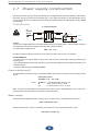
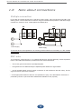
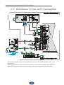
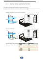
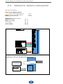
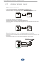
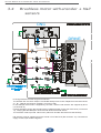
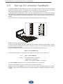
Connection picture as per example. Use shielded wires in case you need longer wires.
2.5
HW direction selection
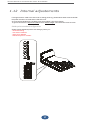
In order to get the change of direction of the motor, without using the feature of inversion by the drive,
the user can procede as follows:
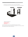
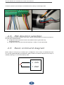
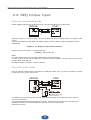
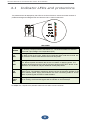
a) Change each other the position of the motor phases U and V (yellow with red)
And at the same time:
b) Change each other the wires of the Hall signal pin 14 and pin 16 (blue with white)
2.6
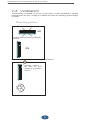
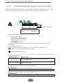
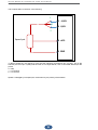
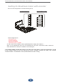
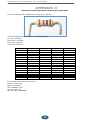
Basic command diagram
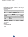
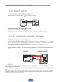
NOTE: close pin 7 onto pin 5 (or connect to pin 7 a voltage from 10 to 24 Vdc). This enables the motor
to run as per speed selected by the speed pot. Start pin does not meet the ramp (even if the ramp is
enabled). Opening pin 7, the motor stops by coast.
5 +9.8V
7 START
24