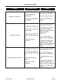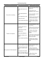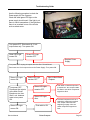
1
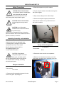
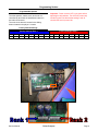
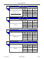
Thank you for your purchase of a Ticket Troopers
We Aspire To Be The Best In The World At
Developing And Manufacturing
Coin Operated Games For Our Customers.
Service Manual
Ticket Troopers
Page 1
Record this information for future reference:
Serial Number:
(Located inside any of the player station door.)
Date of installation:
Installed by:
Service: 920.822.3951 EXT. 1102
Parts: 920.822.3951 EXT. 1107
For 24 hour pricing and ordering please visit us on the web at
www.baytekgames.com
Service Manual
Ticket Troopers
Page 2
Ticket Troopers
ATTENTION OPERATORS….PLEASE BE ADVISED TICKET TROOPERS GAME
PLAY IS ADDICTIVE AND MAY CAUSE MAXIMUM EXCITEMENT…..OVER
Ticket Troopers is a 3 player quick coin game with an exciting police theme.
The players aim the shooters and insert the coins, aiming for the targets directly across.
The continuously spinning playfield adds excitement as the coin speeds across to the other side.
When a target is hit, the game projects flashing red and blue lights.
If the player hits the center target the siren sounds as the player is awarded the big ticket bonus.
The spinning helicopter draws them in as the fast paced game play keeps them there.
Service Manual
Ticket Troopers
Page 3
OPERATION AND SET UP
Safety Precautions
2. Place the marquee on top of the cabinet.
CAUTION: Electric Shock Hazard
3. Plug in marquee cables to the cables coming from
Do not perform repairs or maintenance
the top of the game.
on this game with the power ON.
Unplug the unit from the wall outlet or shut off
4. Snap excess cabling into the cable clamps.
power at the power strip inside the game.
5. Secure the marquee using the provided silver
CAUTION: Electric Shock Hazard
bolts and lock washers. Line up with the holes in
Always plug game into grounded
the top of the cabinet.
circuit.
CAUTION: Use of flammable
substances can cause severe burns
or personal injury.
Always use non-flammable solvents for cleaning
parts and surfaces. Do not use substances such as
gasoline, kerosene, or thinners.
Unpacking, Assembly, and Installation
Inspect the game for any damaged, loose,
or missing parts. If damage is found please
contact the carrier first. Then contact
Set up of Coin Comparators
Bay Tek Games at 920.822.3951 or
( If equipped )
[email protected]
Tools needed:
to order replacement parts.
None
CAUTION: Lifting Hazard.
1. Remove the cover over the coin comparator.
Lifting heavy objects can cause
back, neck, and other injuries.
2. Slide the coin holder back and insert one of the
Be sure adequate lifting and moving devices
coins used in the game room, preferable a new coin:
are available when unloading, unpacking,
and moving this game.
Marquee Installation
Tools required:
7/16 Socket
1. Remove the fully assembled marquee from the
inside of the game. Unpackaged it.
Service Manual
Ticket Troopers
Page 4
Game Set Up
Tools Needed:
None
1. Remove the Styrofoam bracing material from the
helicopter.
5. Replace the Bay Tek test ticket with tickets
of your own.
2. Unroll the power cord from the inside of the game
and feed it thru the hole in the floor. If your location
is equipped with power from the ceiling, the game
has pre-drilled holes to allow for an extension cord
to be used.
6. Roll a few coins thru to ensure the comparators
are working properly and that the correct amount
of tickets are being paid out.
3. Move the game into position and lock all four
casters.
4. Plug in and power on.
Service Manual
7. Adjust the volume to suit your location.
To do so go to any player station ticket tray and
hold down the red button until "SND" appears
on all three of the displays. Then tap the button to
select desired volume level, 1-8. Once done hold the
button down again to return to play mode.
Ticket Troopers
Page 5
Programming Section
Programmable Options
Important: Power must be OFF to the game before
adjusting the dip switches. Turn OFF the power strip
inside the game. Set the desired settings, wait 30
seconds the turn the power ON.
The ticket patterns, attract mode, and more are
controlled by two banks of dipswitches located on
the main circuit board.
The main circuit board is located in the sliding
drawer located in the player 1 location.
Factory Default Settings
Factory Settings Bank 1
Factory Settings Bank 2
Dip 1 Dip 2 Dip 3 Dip 4 Dip 5 Dip 6 Dip 7 Dip 8 Dip 1 Dip 2 Dip 3 Dip 4 Dip 5 Dip 6 Dip 7 Dip 8
OFF
OFF
OFF
Service Manual
OFF
OFF
OFF
OFF
OFF
OFF
OFF
Ticket Troopers
OFF
OFF
OFF
OFF
OFF
OFF
Page 6
Ticket Payout Select - Standard Ticket Patterns
BANK 1 -- DIP 6
Chart
1
Ticket Payout Select
Allows you to choose between a standard ticket
payout or a fixed ticket payout.
Standard Pattern: see charts 2-5
Fixed Pattern: see chart 6
OPTIONS
Dip 8
Fixed Ticket
Payout
on
Standard
Ticket
Payout
OFF
Factory Setting: Standard Ticket Payout
BANK 2 -- DIP 5 - DIP 6 - DIP 7
Chart
2
Pattern
Standard Ticket Patterns
1
2
3
4
Once you have chosen the
pattern see the charts below to
set the bonus ticket number.
Factory Default Setting:
Pattern 1
5
6
7
Ticket Amount
Dip 5 Dip 6 Dip 7
Outside
Drain
Inside
10 Tickets
3 Tickets
5 Tickets
Outside
Drain
Inside
10 Tickets
4 Tickets
6 Tickets
Outside
Drain
Inside
5 Tickets
1 Ticket
3 Tickets
Outside
Drain
Inside
3 Tickets
1 Ticket
2 Tickets
Outside
Drain
Inside
6 Tickets
2 Tickets
4 Tickets
Outside
Drain
Inside
15 Tickets
3 Tickets
10 Tickets
Outside
Drain
Inside
10 Tickets
3 Tickets
5 Tickets
off
off
off
on
off
off
off
on
off
on
on
off
off
off
on
on
off
on
off
on
on
Note: If you choose a different standard pattern, other then the factory default, you will
need to contact Bay Tek Games parts department for a new ticket decals for the target
assemblies.
Service Manual
Ticket Troopers
Page 7
Bonus Ticket Select
Chart
3
BANK 1 -- DIP 7 - DIP 8
Bonus Ticket Select
Bonus ticket selection for standard
patterns 1, 5, or 6.
Factory Setting: 50 Tickets
Chart
4
25 Tickets
on
on
50 Tickets
OFF
OFF
75 Tickets
on
off
100 Tickets
off
on
Bonus
Tickets
Dip 7
Dip 8
30 Tickets
on
on
50 Tickets
off
off
80 Tickets
on
off
100 Tickets
off
on
Bonus
Tickets
Dip 7
Position
Dip 8
Position
10 Tickets
on
on
20 Tickets
off
off
30 Tickets
on
off
50 Tickets
off
on
Bonus
Tickets
Dip 7
Position
Dip 8
Position
100 Tickets
on
on
150 Tickets
off
off
250 Tickets
on
off
200 Tickets
off
on
BANK 1 -- DIP 7 - DIP 8
Bonus Ticket Select
BANK 1 -- DIP 7 - DIP 8
Bonus Ticket Select
Bonus ticket selection for standard
pattern 7.
Service Manual
Dip 8
Bonus Ticket Select
Bonus ticket selection for standard
patterns 3 or 4
Chart
6
Dip 7
BANK 1 -- DIP 7 - DIP 8
Bonus ticket selection for standard
pattern 2
Chart
5
Bonus
Tickets
Ticket Troopers
Page 8
Fixed Ticket Patterns
BANK 1 -- DIP 1 - DIP 2 - DIP 3 - DIP 4
Fixed Ticket Patterns
If you decide to go with the fixed
ticket pattern you may choose to
set the amount of tickets won.
The game will pay out the selected
amount when a coin is inserted
regardless if a target is hit.
Service Manual
Pattern
Chart
7
Ticket
Amount
Dip 1
Dip 2
Dip 3
Dip 4
1
5 Tickets
off
off
off
off
2
6 Tickets
on
off
off
off
3
7 Tickets
off
on
off
off
4
8 Tickets
on
on
off
off
5
9 Tickets
off
off
on
off
6
10 Tickets
on
off
on
off
7
11 Tickets
off
on
on
off
8
12 Tickets
on
on
on
off
Ticket Troopers
Page 9
Mercy Ticket - Attract Mode - Wheel Feedback/Door Cabling - Echo Testing
Chart
8
BANK 2 -- DIP 2 - DIP 3
Mercy Ticket
The game will payout the selected
ticket amount for every play
regardless if a target is scored.
Factory Setting: 0 Tickets
Chart
9
Chart
10
Mercy
Tickets
Dip 2
Dip 3
0 Tickets
OFF
OFF
1 Ticket
on
on
2 Tickets
off
on
3 Tickets
on
off
Bank 2 -- Dip 8
Attract Mode
The attract mode will activate game lighting and
play selected tracks from the audio file every 5
minutes when the game isn't being played.
Options
Dip 8
Enabled
OFF
Factory Setting: Enabled
disabled
on
Bank 2 -- Dip 4
Wheel Feedback/Door Cabling
Allows the software to identify certain revisions to
the game. This dip should not be used unless
otherwise instructed by the Bay Tek service
department.
Factory Setting: Disabled
Chart
11
Dip 4
enabled
on
Disabled
OFF
Options
Dip 1
enabled
on
Disabled
OFF
Bank 2 -- Dip 1
Echo Testing
This dip should not be used unless otherwise
instructed by the Bay Tek service department.
Factory Setting: Disabled
Service Manual
Options
Ticket Troopers
Page 10
Half Ticket Payout - Coin Hopper Equipped
Chart
12
Bank 1 -- Dip 5
Half Ticket Payout
Options
Allows the game to pay half of the tickets won. It
can only be used on standard patterns 2 and 5.
Also on fixed ticket patterns where the tickets won Half Tickets
can be divided by 2.
Factory Setting: Full Tickets
Full Tickets
Dip 5
on
OFF
BANK 1 -- DIP 1 - DIP 2 - DIP 3 - DIP 4
Chart
13
Coin Hopper Equipped
Coins per
Swipe
Dip 1
Dip 2
Dip 3
Dip 4
1 Coin
off
off
off
off
2 Coins
on
off
off
off
3 Coins
off
on
off
off
4 Coins
on
on
off
off
5 Coins
off
off
on
off
6 Coins
on
off
on
off
If the Ticket Troopers is coin hopper
equipped and uses card readers you can
set the number of coins each player
receives with every swipe their card.
7 Coins
off
on
on
off
8 Coins
on
on
on
off
You must also set the dips on each target
assembly board, AABD8801.
9 Coins
off
off
off
on
10 Coins
on
off
off
on
11 Coins
off
on
off
on
12 Coins
on
on
off
on
13 Coins
off
off
on
on
14 Coins
on
off
on
on
15 Coins
off
on
on
on
16 Coins
on
on
on
on
Service Manual
Ticket Troopers
Page 11
AABD8801 Target Assembly - Located on the bottom of each target assembly.
Bank 1 -- Dip 1 - DIP 2 - DIP 2
Player Station Select
Used to set the target for
whichever player station it
assigned to. It is set at the factory
and should not be changed
unless the target is moved or
replaced.
Player
Dip 1
Position
Dip 2
Position
Dip 3
Position
1
on
off
off
2
off
on
off
3
off
off
on
Bank 1 -- Dip 4
Bank 1 -- Dip 5
Coin Hopper Equipped
Player Door Cabling
If the game is equipped with
coin hoppers this dip must be
used.
Factory default is:
No Hoppers
Option
Dip 4
Position
Hoppers
on
No
Hopper
OFF
This dip allows earlier
software to be upgraded.
Use only at the direction of
the Bay Tek service
department.
Factory Default is: Remote
Option
Dip 5
Position
Main
on
Remote
OFF
Bank 1 -- Dip 6
Emitter/Detector Cluster 1
Control the power for
cluster 1 of
emitters/detectors.
Use only during
troubleshooting.
D32 + D17
D29 + D14
D26 + D11
D23 + D8
D20 + D5
D6 + D3
Options
Dip 6
Position
Power off
on
Power On
OFF
Bank 1 -- Dip 7
Emitter/Detector Cluster 2
Control the power for
cluster 2 of
emitters/detectors.
Use only during
troubleshooting.
D31 + D16
D28 + D13
D25 + D10
D22 + D7
D19 + D4
D5 + D2
Options
Dip 7
Position
Power off
on
Power On
OFF
Bank 1 -- Dip 8
Emitter/Detector Cluster 4
Control the power for
cluster 3 of
emitters/detectors.
Use only during
troubleshooting.
Service Manual
D30 + D15
D27 + D12
D24 + D9
D21 + D6
D18 + D3
D4 + D1
Ticket Troopers
Options
Dip 8
Position
Power off
on
Power On
OFF
Page 12
Error Codes
How To Read The Codes
Ticket Troopers is programmed with several error
codes to help identify problems with your game. The
codes will appear on the target assembly that is
affected at power up. Use the pictures below to
identify the issue.
The display will flash Err and the error code.
The first number
indicates the
sensor hole with
the issue.
Service Manual
The second
number indicates
the sensor cluster
failing.
Ticket Troopers
Page 13
Error Codes
Each target hole has a number assigned to it.
That number is the first number of the error code.
Emitter/Detector Clusters
Cluster 1
D32+D17
D29+D14
D26+D11
D23+D8
D20+D5
D6+D3
Cluster 2
D31+D16
D28+D13
D25+D10
D22+D7
D19+D4
D5+D2
Cluster 4
D30+D15
D27+D12
D24+D9
D21+D6
D18+D3
D4+D1
If more then one cluster is failing the program will add
the numbers together to indicate the failing clusters.
EX. If cluster 1 and cluster 4 are failing the program
will show he number 5.
See page 10 for dip assignments.
The second number is the failing cluster. Those
numbers are printed right on the AABD8801 and
AABD8803 boards.
Service Manual
Ticket Troopers
Page 14
Sensor Error Code Chart
The following chart will help you find the
problem with the sensor clusters.
Error Code
Sensor Hole
Emitter
Detector
Error Code
Sensor Hole
Emitter
Detector
11
1
D17
D32
15
1
D 15,17
D 30,32
12
1
D16
D31
16
1
D 15,16
D 30,31
14
1
D15
D30
17
1
D 15,16,17
D 30,31,32
13
1
D 16,17
D 31,32
21
2
D14
D29
25
2
D 14,12
D 29,27
22
2
D13
D28
26
2
D 13,12
D 28,27
24
2
D12
D27
27
2
D 13,12,14
D 27,28,29
23
2
D 14,13
D 29,28
31
3 (BONUS)
D11
D26
35
3 (BONUS)
D 9,11
D 24,26
32
3 (BONUS)
D10
D25
36
3 (BONUS)
D 9,10
D 24,25
34
3 (BONUS)
D9
D24
37
3 (BONUS)
D 9,10,11
D 24,25,26
33
3 (BONUS)
D 11,10
D 26,25
41
4
D8
D23
45
4
D 8,6
D 23,21
42
4
D7
D22
46
4
D 7,6
D 22,21
44
4
D6
D21
47
4
D 8,7,6
D 23,22,21
43
4
D 8,7
D 23,22
51
5
D5
D20
55
5
D 5,3
D 20,18
52
5
D4
D19
56
5
D 4,3
D 19,18
54
5
D3
D18
57
5
D 3,4,5
D 18,19,20
53
5
D 5,4
D 20,19
71
7 (DRAIN)
D3
D6
75
7 (DRAIN)
D 1,3
D 4,6
72
7 (DRAIN)
D2
D5
76
7 (DRAIN)
D 1,2
D 4,5
74
7 (DRAIN)
D1
D4
77
7 (DRAIN)
D 1,2,3
D 4,5,6
73
7 (DRAIN)
D 3,2
D 5,6
Error Code
Sensor Hole
Emitter
Detector
Error Code
Sensor Hole
Emitter
Detector
The most common reason for a sensor failure is that the emitter and detector pair is
slightly out of alignment. Simply adjust the pair to "see" each other better.
If the error still exists you may need to replace the pair.
Contact Bay Tek Games Service at 920.822.3951 Ex. 1102
Service Manual
Ticket Troopers
Page 15
Other Error Codes
Error Code
Problem
Probable Solution
1
Playfield motor moving too
slow or not moving at all
Check the power going to the
motor. Replace the motor or
sensor.
2
Playfield motor moving too
fast.
Check the wiring to the motor
sensor. Replace the sensor.
8
No player position selected for
the target assembly.
Use the dips on the target
assembly to set the player
station, see page 10.
Player Station Error Codes
Error Code
Problem
Probable Solution
81
Coin accepter signal stuck ON
for Trooper 1.
Check the wiring to the coin
comparator. Replace if needed.
82
Coin accepter signal stuck ON
for Trooper 2.
Check the wiring to the coin
comparator. Replace if needed.
83
Coin accepter signal stuck ON
for Trooper 3.
Check the wiring to the coin
comparator. Replace if needed.
91
Reset ticket button stuck ON
for Trooper 1.
Check the wiring to the button.
Replace if needed.
92
Reset ticket button stuck ON
for Trooper 2.
Check the wiring to the button.
Replace if needed.
93
Service Manual
Check the wiring to the button.
Reset ticket button stuck ON
Replace if needed.
for Trooper 3.
Bay Tek Games Service at 920.822.3951 Ex. 1102
Ticket Troopers
Page 16
Preventive Maintenance Section
Maintenance Chart
Use the following maintenance chart as a guide only.
Actual maintenance intervals will depend on usage
and environmental conditions at the location of the
game.
Keep a log of all inspections, even if no problem
exists, with date and time of inspection, action taken.
A sample Repair Record form is included at the end
of this manual.
CAUTION: Use of flammable
substances can cause severe burns or
personal injury.
Always use non-flammable solvents for
cleaning parts and surfaces of this
game. Do not use flammable
substances such as gasoline, kerosene
or thinners.
IMPORTANT: Do not use denatured alcohol, lacquer
thinner or similar solvents to clean the conveyor belt
as they will cause damage to the belt surface.
IMPORTANT: The game should be shut OFF for
cleaning and maintenance.
IMPORTANT: Do not use cleaning solvents on
game graphics. Use only a mild soap solution and
dry with a clean lint free cloth.
Action
Daily
Weekly
Monthly
Fill ticket trays.
Inspect game for physical damage. Repair as
necessary.
Inspect game lighting and replace lamps as
necessary.
Clean outside surfaces and glass
Empty cash box.
Open game and clean playfield and inner
surfaces with a clean soft cloth and warm soapy
water. Do Not use solvents!
Test to insure game is working properly.
Blow ticket dust from ticket dispensers.
Service Manual
Ticket Troopers
Page 17
Troubleshooting Guide
Troubleshooting Strategy
Use common sense and a systematic method of troubleshooting to determine the exact problem, probable
cause and remedy. Use the process of elimination to find the faulty component. Always check for the simple
and obvious causes first such as unplugged, loose or broken wires and bad sensors, bent, pinched, stuck or
jammed components.
Problem
Probable Cause
Remedy
a. Check wall outlet.
a. Unplugged.
b. Blown Fuse.
c. Circuit breaker tripped.
No power to the game.
b. Check transformer fuse
(220v applications only - 7
amp fast burn).
c. Reset power strip breaker
switch or building circuit
breaker. Attempt to determine
cause.
d. Power strip turned off.
e. Bad power supply.
f. AC in-line filter faulty.
d. Check Power strip – it is
located under main board.
e. See power supply
diagnostic. Replace if faulty.
(A5PS1001)
f. Replace AC filter.
(A5FI9222)
a. Increase the volume at any
of the player station doors.
a. Volume too low.
b. Loose wire at control or
speaker.
No Audio
b. Check audio cable
connections to speaker and
main circuit board. Check
continuity.
c. Replace main board with
board from another Gen 5
game if possible to isolate the
problem to the main circuit
d. Door interface board faulty.
board.
c. Main circuit board
malfunction.
d. Replace door interface
board with working station
board.
Service Manual
Ticket Troopers
Page 18
Troubleshooting Guide
Problem
Probable Cause
a. Burned out lamp.
Lighting not functioning.
Remedy
a. Replace lamp with 26 Watt
mini spiral bulb. (A5LI0001)
b. Wiring damaged or
disconnected.
b. Check and repair wiring.
c. Lamp socket damaged or
disconnected.
c. Check and repair faulty
sockets.
a. Check position of toggle. It
is located inside Door # 2
a. Toggle power switch is off.
b. Does motor turn at power
up, then stop?
Turntable not turning.
b. Sensor does not see dull
tab on bottom of table.
Remove table, check sensor,
replace if needed.
(AABD5010)
c. Check for 12 Volts DC at
motor immediately after power
c. If 12 Volts is present,
on.
replace motor. (AAMO8800)
d. Main circuit board
d. Replace main board with
malfunction.
board from another Gen 5
game if possible to isolate the
problem to the main circuit
board.
a. Toggle power switch is off.
a. Check position of toggle. It
is located inside Door # 2
b. Check for 12 Volts DC at
b. If 12 Volts is present,
motor immediately after power replace motor. (AAMO8801)
on.
Helicopter motor does not turn.
c. Check for plastic gear
binding.
d. Main circuit board
malfunction.
Service Manual
Ticket Troopers
c. Replace broken or wore
gear.
d. Replace main board with
board from another Gen 5
game if possible to isolate the
problem to the main circuit
board.
Page 19
Troubleshooting Guide
Problem
Probable Cause
a. Slide which holds coin is
faulty.
Coin mech is not working.
b. Coin speed dipswitch on
mech.
c. SW 1 dipswitch on mech.
d. Faulty coin mech.
e. Door interface board faulty.
Remedy
a. Swap coins in mech.
Ensure slide clean and tight
against coin.
b. Ensure dip on the
comparator is set to 100 ms.
c. Ensure dip SW1 set to NC
(normally closed)
d. Replace mech with working
unit from different station.
e. Replace door interface
board with working station
board.
a. Check connectors. Check
for continuity.
a. Disconnected, loose or
broken wires.
b. Opto Sensor on ticket
dispenser dirty.
Tickets do not dispense.
c. Faulty ticket dispenser.
d. Notch on tickets cut too
shallow.
e. Door interface board faulty.
b. Blow dust from sensor and
clean with isopropyl alcohol.
c. Replace with working
dispenser to isolate the
problem.
d. Flip tickets and load upsidedown to have large cut notch
toward opto sensor.
e. Replace door interface
board with working station
board.
a. Incorrect dipswitch settings. a. Check settings on main
Gen 5 board.
b. Game is scoring too soon –
before coin reaches sensor
b. Sensor board is bad –
board.
Align/clean sensors, replace
Wrong amount of tickets dispensed.
board.(AABD8801A,AABD880
c. Cycle power off, wait 30
3)
seconds, and power back on look for error code on display. c. Refer to Error Codes
section in manual.
Service Manual
Ticket Troopers
Page 20
Troubleshooting Guide
Use the following procedure to check the
Power supply for Gen 5 games.
Check the small green LED light on the
power supply circuit board. If the light is out
there is a short somewhere. If the light dims,
there is an overload in one of the circuits
such as a bad motor.
Turn power OFF. Disconnect all 12 volt
output wires only. Turn power ON.
Green LED Light
comes ON.
Green LED Light
remains OFF.
Replace Power
Supply.
Turn power OFF. Unplug all outputs from the Gen 5 Circuit Board.
Reconnect the 12 volt output wires to the Power Supply. Turn power ON.
Green LED Light
comes ON.
Turn power OFF.
Reconnect the outputs
at the Main Circuit
Board one at a time.
Wait 1 min. between
tests to turn power
ON.
Green LED Light
comes ON.
Service Manual
Green LED Light
remains OFF.
Short in Main Board
- Replace.
Green LED Light
remains OFF.
Green LED Light
dims.
That cable is OK.
Ticket Troopers
That cable or related component
is shorted out. See Jumper Cable
Pin-Outs to see which component
might be at fault.
A related component such as a
solenoid is causing an overload.
See Jumper Cable Pin-Outs
beginning on page 18 to see
which component might be at
fault.
Page 21
Replacing Motors
Turn Table Motor
Helicopter Motor
Tools Needed:
Medium Phillips Screwdriver
1/2" wrench
7/16" wrench
2mm Allen wrench
5/16" wrench
Tools Needed:
1. Remove the vacuum form piece from below any
player station.
1. Remove the shirt using the drill.
Drill with a #2 square bit
1/8" Allen wrench
5/16" wrench
2. Locate the shaft under the turn table and hold it
still using the 1/2" wrench.
2. Remove the helicopter mounting arm using the
1/8 Allen wrench.
3. Unbolt the motor using the 5/16" wrench.
3. Unscrew the turn table from the shaft.
4. Replace the motor and reassemble the unit.
4. Unbolt the motor box from the game using the
7/16" wrench.
5. Remove the pulley from the shaft using the 2mm
Allen wrench.
6. Remove the motor using the 5/16" wrench.
7. Reassembly the motor box with the replacement
motor.
Service Manual
Ticket Troopers
Page 22
Service and Repair
CAUTION: Electric Shock Hazard
Do not perform repairs or maintenance
3. Before installing the new board, check to be sure
on this game with the power ON.
Note: If swapping the board with a spare, remember
the new dipswitches are set.
Unplug the unit from the wall outlet or shut off
to also swap the programming chips. Use extreme
power at the power strip inside the game.
care to prevent static build up and prevent bending
the chip pins.
CAUTION: Static electricity could harm circuit boards
and processor chips. Always ground yourself by cable
or by touching a metal surface prior to working on the
game.
Avoid working on carpeted areas.
4. Install the new board and reconnect the cables.
5. Turn power back on and test the game.
Main Circuit Board
Replacing the main Gen 5 board:
1. With the power off, carefully unplug the various
connectors, black chase light cables, and white (or grey)
display cables.
2. Remove the four screws holding the board to the drawer.
Software Chip
Service Manual
Ticket Troopers
Page 23
Electrical Drawing Section
J1 Connector
RED
12v Input
BLACK
12v Ground
Service Manual
J2 Connector
RED
12v Input
RED
Left
Channel
BLACK
Right
Channel
BLACK
12v Ground
GREEN
Left
Channel
YELLOW
Right
Channel
Ticket Troopers
Page 24
J4 Connector
BLACK
Ticket Meter
RED
Meter Power
WHITE
Game Meter
WHITE
RPM Sensor
Signal 1
BLACK
RPM Grnd.
RED
RPM
Power
Blue
White
Service Manual
Ticket Troopers
Page 25
J5 Connector
BLACK
Chopper
Grnd.
RED
Wheel Motor
Power
RED
Chopper Motor
Power
BLACK
Wheel Ground
Service Manual
Ticket Troopers
Page 26
Gen 5 Main Board Schematics
Service Manual
Ticket Troopers
Page 27
Communications - Serial EEprom
Input Section A - Control Switches
Service Manual
Ticket Troopers
Page 28
Input Section B - Inputs RE, RC
Service Manual
Ticket Troopers
Page 29
Output Section - Chase lights Q13-Q16
Service Manual
Ticket Troopers
Page 30
Output Section B Q17-Q24
Service Manual
Ticket Troopers
Page 31
Output Section C Q5-Q12
Service Manual
Ticket Troopers
Page 32
Power Section
Service Manual
Ticket Troopers
Page 33
Processor Section - Input RD
Service Manual
Ticket Troopers
Page 34
Service Manual
Ticket Troopers
Page 35
Warranty Information
Bay Tek Games Inc. warrants to the original
purchaser that the game will be free of defects
in workmanship and materials for a period of (6)
months from the date of installation.
Repair of NON-Warranty Units
Bay Tek Games Inc. will, without charge, repair or
replace at it's option defective product or component
parts upon notification to the factory service
department.
Warranty replacement part(s) will be shipped
immediately via ground service, along with a Return
Material Authorized (RMA) number for the return
of defective part(s). Defective parts must be shipped
back to Bay Tek Games unless otherwise instructed.
This warranty does not apply in the event of any
misuse or abuse of the product, or as the result of
any unauthorized repairs or alterations.
The warranty does not apply if the serial number
decal is altered, defaced, or removed from its original
position.
Should your game need servicing, determine the
serial number from the decal on the back of the
cabinet or the logic unit, and call 920.822.3951 or
email to:
[email protected]
Service Manual
Should your game need servicing, determine the
serial number from the decal on the back of the
cabinet or the logic unit, and call 920.822.3951 or
email to:
[email protected]
An estimate of the repair charges will be quoted
to you for approval.
You can proceed in one of two ways:
1. Request the immediate shipment of advanced
replacement part(s).
You will receive the part(s) with an RMA for the
return of the faulty part(s). You must return the
faulty parts in 14 days to avoid additional charges.
2. Send in the defective part(s) for repair or
replacement.
Please include the following information:
Name
Address
Phone Number
Serial Number
Purchase Order Number
or Signed Authorization to perform
service
Repair and returned parts will be shipped back
using the same mode of transportation in which
they were received. Repairs are warranted (30) days
from the date installed into service.
Ticket Troopers
Page 36
Repair Record
Make copies of this page for the future
Game
Date
Service Manual
Serial Number
Maintenance Performed
Parts Replaced
Ticket Troopers
Notes
Page 37
Repair Record
Make copies of this page for the future
Game
Date
Service Manual
Serial Number
Maintenance Performed
Parts Replaced
Ticket Troopers
Notes
Page 38
Parts List
Always use genuine Bay Tek Games replacement parts.
For 24 hour pricing and ordering please visit us at
BAYTEKGAMES.COM
Description
Part Number
Tempered Glass - Wedge
Faceplate - Upper Door - Logo
Faceplate - Upper Door - Star
Marquee - Red - Acrylic - 6 per
Door - Acrylic - Clear
Acrylic Coin Slide - Left
Acrylic Coin Slide - Right
Display Board
Turntable Sensor
Large Coin Sensor
Indicator Target Board - Red and Blue Cop Lights
Outside Low Value Sensor
Door Interface Board
Filter Board
Turntable Motor
Helicopter Motor
Helicopter Assembly with Arm
Target Assembly - Complete Score Panel
Blue Beacon Light
Red Beacon Light
Power Supply
Ticket Dispenser
Coin Comparator
Speaker
Toggle Switch
Low Ticket Switch
Player Door Locks (644)
Cashbox Lock (631)
Coin Mech Bracket Box
Coin Mech Handle
Rubber Boot for Coin Assembly
Light Bulb
Decals
Center Wheel
Coin Wall
Inner Deck
Target Front
Target Top
Display (3 per)
Coin Mech Back
Helicopter Skirt
Side Bottom
Door 1
Door 2
Door 3
Helicopter Set
Coin Mech Aim
Outside Instructions
Top of the Side
Alternate Ticket Values
A5TG8801
A5FP8800
A5FP8801
A5AC8802
WATT0027
A5GU8800L
A5GU8800R
AABD2603
AABD5010
AABD8801A
AABD8802
AABD8803
AACB8805
AABD8804
AAMO8800
A5MO8801
AAHE8800
AATT8800
AABA0001
AABA0002
A5PS1001
A5TD1
A5CM-AS-COMP
AACE8811
A5SW0006
AASW200
A5LK5000
A5LK2000
A5BX8802
A5HA8800
A5BU5000
A5LI0001
Service Manual
Ticket Troopers
A5DC8800
A5DC8801
A5DC8802
A5DC8803
A5DC8804
A5DC8805
A5DC8806
A5DC8807
A5DC8808
A5DC8809
A5DC8810
A5DC8811
A5DC8812
A5DC8814
A5DC8815
A5DC8818
A5DC8819
Page 39
Service Manual
Ticket Troopers
Page 40