1
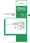
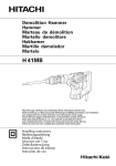
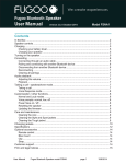
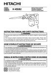
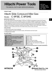
MODEL
H 45MR
POWER TOOLS
HAMMER
H 45MR
LIST No. E463
TECHNICAL DATA
AND
SERVICE MANUAL
MAY 2002
SPECIFICATIONS AND PARTS ARE SUBJECT TO CHANGE FOR IMPROVEMENT
H
REMARK:
Throughout this TECHNICAL DATA AND SERVICE MANUAL, a symbol(s)
is(are) used in the place of company name(s) and model name(s) of our
competitor(s). The symbol(s) utilized here is(are) as follows:
Competitors
Symbols Utilized
Company Name
Model Name
C
MAKITA
HM1100C
B
BOSCH
GSH5E
CONTENTS
Page
1. PRODUCT NAME ...........................................................................................................................1
2. MARKETING OBJECTIVE .............................................................................................................1
3. APPLICATIONS ..............................................................................................................................1
4. SELLING POINTS ..........................................................................................................................1
4-1. Selling Point Descriptions .............................................................................................................. 2
5. SPECIFICATIONS ..........................................................................................................................3
5-1. Optional Accessories ..................................................................................................................... 4
6. COMPARISONS WITH SIMILAR PRODUCTS ..............................................................................6
6-1. Specification Comparison .............................................................................................................. 6
6-2. Demolition Performance Comparison ............................................................................................ 6
6-3. Full-load Vibration Level Comparison ............................................................................................ 7
6-4. Quantity of Working Tool Penetration and Quantity of Body Jumping ........................................... 7
7. PRECAUTIONS IN SALES PROMOTION .....................................................................................8
7-1. Handling Instructions ..................................................................................................................... 8
7-2. Caution Plate ................................................................................................................................. 8
7-3. Grease Replacement ..................................................................................................................... 8
7-4. O-Ring Replacement ..................................................................................................................... 9
8. REFERENCE INFORMATION ........................................................................................................9
8-1. Striking Operation .......................................................................................................................... 9
8-2. Idling-Proof Mechanism ............................................................................................................... 10
8-3. Shock-Absorbing Mechanism ...................................................................................................... 10
8-4. Sealed and Dustproof Construction .............................................................................................. 11
8-5. Vibration Absorbing Construction ................................................................................................. 11
8-6. Tool Retainer ................................................................................................................................ 12
8-7. Adjusting Mechanism for the Tool Swivel Angle ........................................................................... 12
8-8. Side Handle ................................................................................................................................. 12
9. REPAIR GUIDE ............................................................................................................................13
9-1. Precautions and Suggestions for Disassembly and Reassembly of the Main Body .................... 13
10. STANDARD REPAIR TIME (UNIT) SCHEDULES .....................................................................18
Assembly Diagram for H 45MR
1. PRODUCT NAME
Hitachi Electric Hammer, Model H 45MR
2. MARKETING OBJECTIVE
The Model H 45MR is an upgraded version of the current Model H 45MA, which features the use of maker B's
SDS-max shank tools. The performance, durability and operability are greatly improved. With this competitive
Model H 45MR, we aim to enhance the share of the SDS-max type hammers.
The main specifications are as follows:
(1) High chipping and demolishing performance with low vibration and noise level
(2) Self-chiseling (Good feeling)
(3) Internal double-insertion construction with sturdy aluminum frame
(4) A highly reliable mechanism for prevention of idle hammering and shock-absorbing mechanism results in
prolonged service life and comfortable operation.
(5) D-type side handle with adjustable mechanism for 360˚ rotation plus positioning from front to rear
(6) Soft-touch grip for easier handling
(7) Simply turning method, variable lock mechanism for easy working-angle adjustment of chisels, etc.
(8) A very original design
3. APPLICATIONS
Demolishing and chiseling of concrete
Edging, gravel road digging, compacting and tamping, grooving, cutting, stripping and roughing, etc.
4. SELLING POINTS
High chipping and demolishing performance with low vibration and noise level
Self-chiseling (Good feeling)
A very original design
A highly reliable mechanism for prevention of idle
hammering and shock-absorbing mechanism results
in prolonged service life and comfortable operation.
Hitachi original design
vibration-absorbing handle for
excellent vibration reduction
Simply turning method, variable lock
mechanism for easy working-angle
adjustment of chisels, etc.
Large trigger switch for
comfortable operation
D-type side handle with adjustable
mechanism for 360˚ rotation plus
positioning from front to rear
Internal double-insulation construction
with sturdy aluminum frame
--- 1 ---
Soft-touch grip
for easier handling
4-1. Selling Point Descriptions
4-1-1. High chipping and demolishing performance with low vibration and noise level
Demolition performance is 1.2 to 1.5 times higher than that of similar products thanks to the 12.5 J impact energy
and efficient striking. The chipping performance is 1.2 to 1.5 times higher than that of similar products. Even so,
the Model H 45MR produces equivalent or lower vibration and sound levels than those of similar products.
Maker • Model
HITACHI
H 45MR
HITACHI
H 45MA
C
B
Ratio of demolished weight
%
100
66
67
86
Full-load vibration level
dB (VL)
119.0
119.5
119.5
122.0
Full-load noise level
dB (A)
95.9
95.6
94.7
95.3
No-load noise level
dB (A)
82.5
86.7
*82.7
*85.4
* C and B: Equipped with constant speed control
4-1-2. Self-chiseling (Good feeling)
Thanks to the computer-simulated optimum striking characteristics, the quantity of body jumping is less than that
of the current Model H 45MA and the working tool smoothly penetrates into the workpiece with a light pressing
force. The Model H 45MR realizes quicker self-chiseling with better impact feeling.
Impact energy
40% up (9.0 J to 12.5 J)
Maximum compressed air force (piston force)
About 30% down
Quantity of body jumping
About 45% down
4-1-3. Internal double-insulation construction with sturdy aluminum frame
The aluminum die-cast outer frame is very sturdy (highly rigid). In addition, a plastic internal S holder is adopted
to realize double-insulation construction. Thus the housing has greater rigidity and the double-insulated motor
has greater durability. The Model H 45MR is heavy-duty and the service life of the carbon brush is greatly
prolonged (3 times longer than the conventional one) minimizing disconnection of the armature, deviation of the
core and grease leakage.
4-1-4. A highly reliable mechanism for prevention of idle hammering and shock-absorbing mechanism results
in prolonged service life and comfortable operation
Conventional mechanism for prevention of idle hammering is to open and close the air holes according to the
movement of the striker. The Model H 45MR has air holes located at the position unaffected by the rebound of
the striker at no load. The air holes are opened and closed by the movement of sleeve (A) provided around the
cylinder that interlocks with the tool and the second hammer to prevent idle hammering. This mechanisms
securely prevents idle hammering even in wall hammering works or even if a tool that can cause great rebound on
the striker such as a cutter is used. Thanks to the highly reliable mechanism for prevention of idle hammering, the
service life of the Model H 45MR is prolonged and hammering works requiring much attention not to break the
surroundings can be efficiently performed with the Model H 45MR. At the instance of releasing the bull point from
the concrete by moving the main body up, the second hammer contacts hammer holder (A) then the cushion
(damper (A)) provided between hammer holder (A) and the front cover absorbs the striking force of the second
hammer. Thus the Model H 45MR has greater durability than the similar products.
--- 2 ---
4-1-5. D-type side handle with adjustable mechanism for 360˚ rotation plus positioning from front to rear
The D-type side handle can be adjusted by 360˚ rotation and also allows convenient operation from front to rear.
This side handle has a two-layer plastic construction (integral molding) made of nylon resin as the base and soft
resin around it for a comfortable cushion grip.
4-1-6. Soft-touch grip for easier handling
The double-layer molded handle consists of a nylon resin base covered with a soft plastic layer to ensure a soft
touch and firm, non-slip grip of the handles.
4-1-7. Simply turning method, variable lock mechanism for easy working-angle adjustment of chisels, etc.
The tool swivel angle can be easily changed in 12 steps by pushing out grip (B) ahead and then turning grip (A).
4-1-8. Original design vibration-absorbing handle (Vibration-absorbing is significantly improved)
Hitachi's original design vibration-absorbing handle minimizes vibration through the rolling and compression of
four cylindrical rubber cushions on inclined surfaces. The spring constant factor is as low as that of the Models
H 45SB2, H 41SC, H 45SR, H 60KA, H 60MA and H 60MB, and the cushioning structure greatly reduces
vibration.
5. SPECIFICATIONS
Power source
Single-phase AC 50/60 Hz
Voltage
110 V, 120 V, 220 V, 230 V, 240 V
Motor type
AC single-phase series commutator motor
Insulation structure
Double insulation
Enclosure
Switch
Materials: Aluminum alloy die casting
Nylon resin (Handle, tail cover and crank cover)
Paint
: Silver green metallic, black
Trigger switch (with stopper)
Type of handles
D-shaped handle and side handle
Full-load current
For Europe, Australia, U.S.A.
For Asia, etc.
9.1 A (110 V), 8.3 A (120 V),
5.0 A (220 V)
4.4 A (230 V), 4.2 A (240 V)
950 W
Power input
Striking speed
1,050 W
No-load : 4,000 min-1
Full-load : 3,000 min-1
Weight
Product : 5.9 kg (13.0 lbs.); excluding cord and side handle
Packed : 10.2 kg (22.5 lbs.)
Packaging
Standard accessories
Corrugated cardboard box with plastic tool case
Bull point 280 mm (11-1/32")
Side handle
• • • • • • • • • • • • • • • • • • • • • • • • • • • • • • • • • • • • • • • • • • • • • • • • • • • • • • • • • • •
• • • • • • • • • • • • • • • • • • • • • • • • • • • • • • • • • • • • • • • • • • • • • • • • • • • • • • • • • • • • • • • • • • • • • • • • • • • • • • • • • •
1 pc.
1 pc.
Hex. bar wrench (for M6)
• • • • • • • • • • • • • • • • • • • • • • • • • • • • • • • • • • • • • • • • • • • • • • • • • • • • • • • • • • • • • • • •
1 pc.
Hex. bar wrench (for M5)
• • • • • • • • • • • • • • • • • • • • • • • • • • • • • • • • • • • • • • • • • • • • • • • • • • • • • • • • • • • • • • • •
1 pc.
Hex. bar wrench (for M4)
• • • • • • • • • • • • • • • • • • • • • • • • • • • • • • • • • • • • • • • • • • • • • • • • • • • • • • • • • • • • • • • •
1 pc.
• • • • • • • • • • • • • • • • • • • • • • • • • • • • • • • • • • • • • • • • • • • • • • • • • • • • • • • • • • • • • • • • • • • • • • • • • • • •
1 pc.
Plastic tool case
--- 3 ---
5-1. Optional Accessories
(1) Demolition work
(1) Bull point (SDS max shank type)
Overall length
Code No.
280 mm (11-1/32")
313471
400 mm (15-3/4")
313472
(2) Grooving and chiseling work
(1) Cold chisel (SDS max shank type)
Overall length
Code No.
280 mm (11-1/32")
313473
400 mm (15-3/4")
313474
(3) Cutting and stripping work (asphalt cutting, etc.)
(1) Cutter (SDS max shank type)
Width
Overall length
Code No.
50 mm (2")
400 mm (15-3/4")
313475
(4) Digging (substitute pick-ax)
(1) Scoop (SDS max shank type)
Overall length
Code No.
400 mm (15-3/4")
313476
--- 4 ---
(5) Roughing surface work
(1) Bushing tool
(2) Shank (SDS max shank type)
Code No.
Overall length
Code No.
313477
220 mm (8-21/32")
313479
(6) Tamping work
(1) Rammer
(2) Shank (SDS max shank type)
Code No.
Overall length
Code No.
313478
220 mm (8-21/32")
313479
150 mm x 150 mm
(7) Grease for impact drill
500 g (1.1 lbs.) Can
Code No. 980927
70 g (2.5 oz) Tube
Code No. 308471
(Note)
Code numbers listed above are subject to change without notice.
Please refer to periodic Technical News Bulletins.
--- 5 ---
30 g (1 oz) Tube
Code No. 981840
6. COMPARISONS WITH SIMILAR PRODUCTS
6-1. Specification Comparison
HITACHI
Maker
H 45MR
Model name
C
B
870
1,050
1,100
12.5
9.0
4.7 --- 9.6
2.0 --- 12.0
min
3,000
3,000
1,300 --- 2,650
2,900
Full-load vibration level
dB(VL)
119.0
119.5
119.5
122.0
Full-load noise level
dB(A)
95.9
95.6
94.7
95.3
No-load noise level
dB(A)
82.5
86.7
82.7
85.4
Length
mm
454
(17-7/8")
445
(17-33/64")
524
(20-5/8")
450
(17-23/32")
Height
mm
230
(9-1/16")
210
(8-9/32")
224
(8-13/16")
230
(9-1/16")
Width
mm
106
(4-11/64")
106
(4-11/64")
98
(3-55/64")
102
(4-1/64")
kg
5.9
(13.0 lbs.)
5.4
(11.9 lbs.)
6.1
(13.5 lbs.)
5.4
(11.9 lbs.)
Power input
W
Striking energy per stroke
J
For
Asia
etc.
H 45MA
950
1,050
-1
Full-load impact rate
Dimensions
For Europe,
Australia,
U.S.A.
Weight (without cord and
side handle)
Double insulation
Insulation structure
Double insulation Double insulation
Double insulation
6-2. Demolition Performance Comparison
The data shown in Fig. 1 are obtained in actual factory tests, and are for reference only. Demolished amount may
vary in accordance with operating conditions, operator skill, etc.
Demolished weight
for 30 min. (kg)
0
20
40
H 45MR
H 45MA 53
At rated
voltage
C
54
B
Fig. 1
--- 6 ---
Demolished amount
(kg/30 min.)
80
60
70
81
6-3. Full-load Vibration Level Comparison
The graph shown in Fig. 2 illustrates the relationship between handle pressing force and handle vibration level in
the Z direction.
126.0
Z
HITACHI H 45MR
HITACHI H 45MA
Vibration level (dB (VL))
124.0
C
B
Normal pressing force range
122.0
120.0
118.0
116.0
114.0
100
250
200
150
Pressing force (load) (N)
Fig. 2
6-4. Quantity of Working Tool Penetration and Quantity of Body Jumping
The graph shown in Fig. 3 illustrates the relationship between ratio of
quantity of working tool penetration and ratio of quantity of body jumping.
The quantity of body jumping is less than the similar products and the
working tool quickly penetrates into the workpiece.
Ratio of quantity of
body jumping
Pressing force: 100N
1.20
1.0
1.00
0.96
0.54
0
Ratio of quantity of
working tool penetration
50
100
100
102
130
150
150
H 45MR
H 45MA
B
C
Fig. 3
--- 7 ---
7. PRECAUTIONS IN SALES PROMOTION
In the interest of promoting the safest and most efficient use of the Model H 45MR Electric Hammer by all of our
customers, it is very important that at the time of sale the salesperson carefully ensures that the buyer seriously
recognizes the importance of the contents of the Handling Instructions, and fully understands the meaning of the
precautions listed on the Caution Plate attached to each tool.
7-1. Handling Instructions
Although every effort is made in each step of design, manufacture and inspection to provide protection against
safety hazards, the dangers inherent in the use of any electric tool cannot be completely eliminated. Accordingly,
general precautions and suggestions for the use of electric power tools, and specific precautions and suggestions
for the use of the Electric Hammer are listed in the Handling Instructions to enhance the safe, efficient use of the
tool by the customer. Salespersons must be thoroughly familiar with the contents of the Handling Instructions to
be able to offer appropriate guidance to the customer during sales promotion.
7-2. Caution Plate
The Model H 45MR unit is provided with a Caution Plate (illustrated below) which lists basic safety precautions in
use. Carefully ensure that the customer fully understands and follows these precautions before using the tool.
For Australia
For the U.S.A. and Canada
7-3. Grease Replacement
The striking portion and the speed reduction portion of the Model H 45MR respectively use different types of
grease. Grease replacement is required if the unit is disassembled for maintenance of O-rings become damaged
and worn as described in 7-4.
The striking portion uses special grease. If the striking portion (inside the cylinder crank case) is disassembled,
thoroughly remove all of the old grease from each part. On reassembly, insert 53 g (1.9 oz) of new grease into
the cylinder crank case (connecting rod side). Do not exceed the designated amount of grease. Excessive
grease insertion may cause reduced striking performance.
The speed reduction portion (inside the gear cover) uses Hitachi Motor Grease No. 29 (Code No. 930035). The
proper supply volume is 20 g (0.7 oz). Never use the striking portion special grease in the speed reduction
portion. Special grease would leak into the motor portion and cause subsequent trouble.
--- 8 ---
7-4. O-Ring Replacement
The O-rings (mounted on the striker and piston) are extremely important to ensure adequate sealing of the air
pressure. Although the O-rings are made of special rubber to give them a long service life, they do nonetheless
become worn, and should be replaced by new ones periodically depending on frequency of use of the tool. With
average use, it is recommended that the O-rings be replaced at least every six months to ensure maximum
effectiveness.
8. REFERENCE INFORMATION
Structure:
Crank cover
Second hammer
O-rings
Striker
Connecting rod
Crank shaft
Air chamber
Cylinder
Piston
Armature
Fig. 4
8-1. Striking Operation
The rotation of the armature is transferred to the crank shaft and connecting rod, which in turn cause the piston to
reciprocate inside the cylinder. As the piston reciprocates, the changing air pressure inside the air chamber
between the piston and the striker causes the striker to continuously strike against the end of the second hammer.
At the same time, the air-cushion effect within the air chamber absorbs the impact of the striker. Should the air
escape from the air chamber, the air-cushion effect would cease, and the impact energy would not be absorbed.
Accordingly, the O-rings mounted on the striker and piston play an extremely important role in sealing the air
within the air chamber.
--- 9 ---
8-2. Idling-Proof Mechanism
When the bull point is released from the concrete surface, sleeve (A) and the second hammer are forcibly moved
to the position illustrated in Fig. 5 by spring (C), and the striker moves out of striking position. When this occurs,
the air holes located at the position unaffected by the rebound of the striker at no load are opened and the
pressure within the air chamber remains unchanged even though the piston continues to reciprocate, thereby
preventing striking operation.
Second hammer
Striker
Sleeve (A)
Spring (C)
Air
chamber
Forward movement of
second hammer & striker
Air hole
Fig. 5
8-3. Shock-Absorbing Mechanism
At the instance of releasing the bull point from the concrete by moving the main body up, the second hammer
contacts hammer holder (A) then the cushion (damper (A)) provided between hammer holder (A) and the front
cover absorbs the striking force of the second hammer. Thus the durability of the Model H 45MR is increased
greatly because the second hammer does not strike the tool retainer directly.
Second hammer
Hammer holder (A)
Damper (A)
Fig. 6
--- 10 ---
Vibration absorbing unit
O-ring
Switch handle
Cylinder crank case O-ring
O-ring
O-ring
Retainer sleeve
Front cover
Oil seal
Housing
Fig. 7
Vibration
absorbing
unit
8-4. Sealed and Dustproof Construction
The cylinder crank case is sealed by four O-rings and an oil seal which serve to prevent leakage of the grease, as
well as to prevent dust and dirt from entering the mechanism.
8-5. Vibration Absorbing Construction
Hitachi original, innovative units which absorb vibration are installed between the switch handle and the cylinder
crank case and between the switch handle and the housing. As a result, the amount of vibration transmitted from
the main body to the arms of the operator is considerably less in comparison with conventional hammers.
Construction of vibration absorbing unit:
Cylindrical rubbers (handle damper: 4 pcs.)
The main body (cylinder crank case and
Handle damper
retaining material
(handle side)
Slotted groove
housing) and the handle are connected through
four cylindrical rubbers (handle dampers).
Cylindrical
convex
Vibration is absorbed by the rolling and
compression of the four rubbers on inclined
surfaces. Because the vibration absorbing unit
has non-linear spring characteristics, its spring
constant factor is lower than that of the
Handle damper retaining material
(Cylinder crank case and housing)
conventional shearing rubber type vibrationabsorbing construction, and it provides
Vibrationproof rubbers Handle side
significantly higher efficiency in minimizing
Rolled and compressed
Pressing
force of the
main body
vibration. In addition, the interlocking slotted
groove and cylindrical convex portions at the
center prevent the handle from being
disconnected by twisting or pulling, a common
Main body side
Reaction
(a) At no-load
problem with conventional hammers.
(b) At full-load
Fig. 8
--- 11 ---
8-6. Tool Retainer
The Model H 45MR is equipped with a slide-type tool retainer. Tools can be attached and detached just by pulling
grip (A). While pulling grip (A) in A direction, insert the tool in the hole of the front cap (Fig. 9). Adjust the groove
position by turning the tool and push it in to the end. Lock the tool by returning grip (A) back to the original
position.
Grip (A)
A
Tool shank
Front cap
Fig. 9
8-7. Adjusting Mechanism for the Tool Swivel Angle
The tool swivel angle can be easily changed in 12 steps. The tool swivel angle can be set freely to the desired
position by pushing out grip (B) ahead in A direction and then turning grip (A) in B or C direction. (Fig. 10)
B
C
A
Grip (A)
Grip (B)
Fig. 10
8-8. Side Handle
The side handle can be adjusted by 360˚ rotation and also allows operation from front to rear. Loosen the handle
by turning the grip in A direction and adjust the handle to a convenient position. Turn the grip in B direction to
fix the side handle. (Fig. 11)
Grip
A
B
Fig. 11
--- 12 ---
9. REPAIR GUIDE
9-1. Precautions and Suggestions for Disassembly and Reassembly of the Main Body
The numbers in [Bold] correspond to the item numbers in the Parts List and exploded assembly diagrams.
9-1-1. Disassembly
Retainer disassembly (See Figs. 12 and 13.)
Pull Grip (A) [2] fully in the arrow direction as shown in
Fig. 12 and remove the Front Cap [1] (since the Front
Cap [1] is made of rubber and engaged firmly with the
Retainer Sleeve [16], pull it strongly to remove). This
allows Grip (A) [2] to be separated from the Retainer
Front cap
Sleeve [16].
Needle roller D8 x 20
(2 pcs.)
Ball holder
Grip (A)
Fig. 12
Grip (C)
Grip (B)
Ring
Needle holder
Retainer sleeve
Spring (A)
Retainer ring
Steel ball
(4 pcs.)
Front cover
Fig. 13
Remove the Ring [3] by means of a snap ring remover, then the Needle Holder [4], the two Needle Rollers
D8 x 20 [5] and Spring (A) [6] can be removed from the Retainer Sleeve [16]. Remove the Retaining Ring
D42 [7] by means of a snap ring remover, then the Ball Holder [8], Grip (B) [9] and the four Steel Balls D6.35
[11] can be removed from the Front Cover [13]. Furthermore, remove the Retaining Ring D42 [7] by means
of a snap ring remover, then Grip (C) [10] can be removed from the Front Cover [13]. (Fig. 13)
Piston and striker disassembly
Remove the Seal Lock Hex. Socket Hd. Bolts M6 x 25 [12] fixing the Front Cover [13], then the Retainer
Sleeve [16] and the Front Cover [13], Hammer Holder (A) [18], Damper (A) [17], Second Hammer [20],
Hammer Holder (B) [22], Damper (B) [23], Washer [24], Hammer Holder (C) [25], Damper (C) [21], Cylinder
Holder [28], Cylinder [31], Sleeve (A) [29] and Spring (C) [30] can be removed from the Cylinder Crank Case
[48]. The Striker [26] can be removed by tapping the Cylinder [31] lightly with a plastic hammer. As the
Piston [33] remains in the Cylinder Crank Case [48] side, remove the Seal Lock Hex. Socket Hd. Bolts
M4 x 12 [36] fixing the Crank Cover [38], then the Crank Cover [38] can be removed from the Cylinder Crank
Case [48], and remove the Retaining Ring for D10 Shaft [41] to remove the Connecting Rod [34] from the
Crank Shaft [42].
--- 13 ---
First gear and crank shaft disassembly
Remove the grease from the Connecting Rod [34] side and the First Gear [53] side of the Cylinder Crank
Case [48]. Remove the two Seal Lock Hex. Socket Flat Hd. Bolts M5 x 12 [44] fixing Bearing Cover (A) [45].
Then place the Connecting Rod [34] side of the Cylinder Crank Case [48] downward on a workbench and
apply pressure on the end surface of the Crank Shaft [42] with a hand press to remove the First Gear [53] and
the Crank Shaft [42] (Fig. 14). Before removing them, make sure that the two Seal Lock Hex. Socket Flat Hd.
Bolts M5 x 12 [44] fixing Bearing Cover (A) [45] are removed.
Crank Shaft
Apply pressure on the end
surface of the crank shaft
with a hand press.
Cylinder Crank Case
First Gear
Bearing Cover (A)
Workbench
Fig. 14
9-1-2. Reassembly
Reassembly can be accomplished by following the disassembly procedure in reverse. However, special attention
should be given to the following items.
First gear and crank shaft reassembly
Press-fit the Ball Bearing 6203DDCMPS2L [46] in the Cylinder Crank Case [48] and fix Bearing Cover (A) [45]
with the two Seal Lock Hex. Socket Flat Hd. Bolts M5 x 12 [44]. Press-fit the Crank Shaft [42]. Then mount
the Oil Seal [47]. Put the Feather Key 4 x 4x 10 [43] into the groove of the Crank Shaft [42] and press-fit the
First Gear [53] with a suitable tool while holding the flat portion of the Crank Shaft [42] with a steel bar. Before
press-fitting, make sure that the Feather Key 4 x 4 x 10 [43] fits in the key groove of the First Gear [53]. (Fig.
15)
Suitable tool
Feather key
First gear
Oil seal
Ball bearing
Hex. socket hd. flat
bolt M5
Bearing cover (A)
Cylinder crank case
Crank shaft
Steel bar
Fig. 15
--- 14 ---
Piston reassembly
Insert the Piston Pin [32] into the D8 hole (marked) of the Piston [33] and the Connecting Rod [34] then pressfit it. Be careful not to protrude the Piston Pin [32] from the outside diameter of the Piston [33]. Move the
crank pin of the Crank Shaft [42] to the bottom dead center and insert the piston ass'y into the Crank Shaft
[42] from the cylinder case of the Cylinder Crank Case [48]. Mount the Retaining Ring for D10 Shaft [41]
using a retaining ring puller.
Piston pin
D8 hole
Mark
Retaining ring
Crank pin portion
Crank shaft
Connecting rod
O-ring
Piston
Cylinder crank case
Fig. 16
Cylinder reassembly
Move the crank pin of the Crank Shaft [42] then move the Piston [33] to the top dead center. Insert the
Cylinder [31] into the Cylinder Crank Case [48].
Cylinder
Piston
Crank pin portion
Cylinder crank case
Crank shaft
Fig. 17
Lubrication
Apply special grease (grease for electric impact drills) to the inner circumference of the Connecting Rod [34],
the O-rings [27] in the Striker [26] and in the Piston [33], the outer circumference of the Retainer Sleeve [16],
the sliding portion of the Second Hammer [20], the Oil Seal [47], Damper (A) [17], Damper (B) [23], Damper
(C) [21], the inner circumference of Sleeve (A) [29], Hammer Holder (B) [22], Hammer Holder (C) [25], and
the end surface of Spring (A) [6]. Seal 53 g of the special grease into the Cylinder Crank Case [48] (the
Connecting Rod [34] side).
Apply Hitachi Motor Grease No. 29 to the Needle Bearing (M661) [54], the pinion portion of the Armature [70],
the Needle Roller D8 x 20 [5] and the Steel Ball D6.35 [11]. Seal 20 g of the Hitachi Motor Grease No. 29 into
the Cylinder Crank Case [48] (the First Gear [53] side).
--- 15 ---
Oil seals
Be very careful not to damage the O-ring (1AS-50) [15] on the Front Cover [13], the O-ring (S-34) [14] in the
Front Cover [13], the O-ring (S-25) [19] in Hammer Holder (A) [18], the O-ring (1AS-60) [40] in the Crank
Cover [38], the O-rings [27] in the Striker [26] and in the Piston [33], and the Oil Seal [47] in the Cylinder
Crank Case [48].
9-1-3. Screw locking agent TB1401
Apply screw locking agent TB1401 to all hex. socket hd. bolts M4, M5 and M6.
Caution: If bolts are loosened by vibration, it could cause damage to the hammer body. Ensure without
fail that screw locking agent is applied to threaded portions prior to reassembly.
9-1-4. Tightening torque
(1) Attached bolts of front cover
13.7+ 00.98 N•m (140 + 100 kgf•cm, 121.5 + 08.7 in-Ibs.)
(Hex. socket hd. bolts M6 x 25)
(2) Attached bolts of bearing cover (A)
4.41
0.49 N•m (45
5 kgf•cm, 39.1
4.3 in-Ibs.)
2.94
0.49 N•m (30
5 kgf•cm, 26.0
4.3 in-Ibs.)
(Hex. socket hd. flat bolts M5 x 12)
(3) Tapping screws D5
(4) Hex. socket hd. bolts M6 x 45
9.8
+1.96
0
(5) Attached bolts of tail cover
4.9
+1.96
0
N•m (100
N•m (50
+20
0
+20
0
kgf•cm, 86.8 +17.4
in-Ibs.)
0
kgf•cm, 43.4 +17.4
in-Ibs.)
0
(Hex. socket hd. bolts M5 x 10)
(6) Attached bolts of crank cover
4.41
0.49 N•m (45
5 kgf•cm, 39.1 4.3 in-Ibs.)
1.96
0.49 N•m (20
5 kgf•cm, 17.4 4.3 in-Ibs.)
(Hex. socket hd. bolts M4 x 12)
(7) Tapping screws D4
(8) Attached bolts of handle
4.9 +1.96
N•m (50
0
+20
0
kgf•cm, 43.4 +17.4
in-Ibs.)
0
(Hex. socket hd. bolts M5 x 12)
(9) Attached bolts of internal wire holder
7.84 +1.96
N•m (80 +20
kgf•cm, 69.4 +17.4
in-Ibs.)
0
0
0
(Hex. socket hd. bolts M5 x 14)
--- 16 ---
9-1-5. Internal wiring
Wiring diagram for products with noise suppressor
Switch
Stator
Connector
Brown
Plug
Connector
Noise
suppressor
Armature
Blue
Pillar terminal
Stator
Fig. 18
Wiring diagram for products without noise suppressor
Switch
Stator
Black
Plug
Armature
White
Connector
Stator
Fig. 19
9-1-6. Insulation tests
On completion of disassembly and repair, measure the insulation resistance and dielectric strength.
Insulation resistance: 7 MΩ or more with DC 500 V Megohm Tester
Dielectric strength:
AC 4,000 V/1 minute, with no abnormalities
• • •
220 V --- 240 V
(and 110 V for U.K. products)
AC 2,500 V/1 minute, with no abnormalities
• • •
110 V --- 127 V
(except U.K. products)
9-1-7. No-load current value
After no-load operation for 30 minutes, the no-load current value should be as follows:
Voltage (V)
110
120
220
230
240
Current (A) (Max.)
3.8
3.5
2.2
2.1
2.0
--- 17 ---
10. STANDARD REPAIR TIME (UNIT) SCHEDULES
MODEL
Variable
Fixed
10
20
30
40
50
60 min.
Work Flow
H 45MR
Gear Cover
Ass'y
Needle Bearing
Switch (B)
Cord
Tail Cover
Housing Ass'y
Stator Ass'y
Armature Ass'y
Ball Bearing
(6201DD)
Ball Bearing
(608VV)
Dust Washer (B)
Washer (A)
Crank Cover
O-ring
General Assembly
Side Handle
Ass'y
Front Cap
Grip (A)
Needle Holder
Ball Holder
Grip (B)
Grip (C)
Handle (A)
Handle (B)
Transatory Unit
Crank Shaft
Cylinder Crank
Case
Key (4x4x10)
Ball Bearing
(6203DD)
Oil Seal
First Gear
Striker
O-ring x 2
Piston
Piston Pin
Connecting Rod
Sleeve (A)
Spring (C)
Cylinder
Front Cover
O-ring (S-34)
O-ring
(1AS-50)
Retainer
Sleeve
Spring (A)
Damper (A)
Hammer
Holder (A)
O-ring (S-25)
Second
Hammer
Damper (B)
Damper (C)
Hammer
Holder (B)
Hammer
Holder (C)
Cylinder Holder
--- 18 ---
LIST NO. E463
ELECTRIC TOOL PARTS LIST
HAMMER
Model H 45MR
2002 • 5 • 30
(E1)
1
2
9
36
3
7
4
5
10
37
6
3
11
38
7
12
8
13
21
39
14
22
23
40
15
24
41
16
25
26
17
27
42
28
18
43
19
29
20
30
44
31
56
45
27
32
57
46
33
34
47
58
35
48
59
49
68
58
50
51
69
52
61
70
57
60
71
53
72
54
73
55
92
74
90
89
75
501
83
84
88
76
86
87
85
77
502
91
84
83
78
79
64
503
80
51
63
96
62
95
504
94
101
93
505
102
65
100
99
81
66
98
82
97
52
67
83
84
84
83
103
104
PARTS
ITEM
NO.
1
CODE NO.
NO.
USED
DESCRIPTION
315-529
FRONT CAP
1
2
320-802
GRIP (A)
1
3
320-803
RING
2
4
320-804
NEEDLE HOLDER
1
5
313-421
NEEDLE ROLLER D8X20
2
6
320-806
SPRING (A)
1
7
317-088
RETAINING RING D42
2
8
320-810
BALL HOLDER
1
9
320-807
GRIP (B)
1
10
320-808
GRIP (C)
1
11
959-150
STEEL BALL D6.35 (10 PCS.)
4
12
981-942
SEAL LOCK HEX. SOCKET HD. BOLT M6X25
4
13
320-809
FRONT COVER
1
14
980-879
O-RING (S-34)
1
15
990-067
O-RING (1AS-50)
1
16
320-805
RETAINER SLEEVE
1
17
320-812
DAMPER (A)
1
18
320-811
HAMMER HOLDER (A)
1
19
319-572
O-RING (S-25)
1
20
320-813
SECOND HAMMER
1
21
320-817
DAMPER (C)
1
22
320-814
HAMMER HOLDER (B)
1
23
320-815
DAMPER (B)
1
24
320-835
WASHER
1
25
320-816
HAMMER HOLDER (C)
1
26
320-822
STRIKER
1
27
320-823
O-RING
2
28
320-818
CYLINDER HOLDER
1
29
320-820
SLEEVE (A)
1
30
320-821
SPRING (C)
1
31
320-819
CYLINDER
1
32
320-826
PISTON PIN
1
33
320-824
PISTON
1
34
320-825
CONNECTING ROD
1
35
986-940
SEAL LOCK HEX. SOCKET HD. BOLT M6X45
4
36
983-162
SEAL LOCK HEX. SOCKET HD. BOLT M4X12
4
HITACHI LABEL
1
320-831
CRANK COVER
1
HITACHI LABEL
1
40
956-996
O-RING (1AS-60)
1
41
939-540
RETAINING RING FOR D10 SHAFT (10 PCS.)
1
42
320-829
CRANK SHAFT
1
43
930-511
FEATHER KEY 4X4X10
1
44
980-760
SEAL LOCK HEX.SOCKET FLAT HD. BOLT M5X12
2
45
980-761
BEARING COVER (A)
1
37
38
39
*
H 45MR
46
620-3DD
BALL BEARING 6203DDCMPS2L
1
47
310-119
OIL SEAL
1
48
320-828
CYLINDER CRANK CASE
1
NAME PLATE
1
49
50
320-837
HANDLE PACKING (A)
1
51
310-124
HANDLE DAMPER
8
--- 2 ---
* ALTERNATIVE PARTS
REMARKS
5 -- 02
PARTS
ITEM
NO.
52
H 45MR
CODE NO.
NO.
USED
DESCRIPTION
310-123
TRANSATORY UNIT
2
53
320-830
FIRST GEAR
1
54
939-299
NEEDLE BEARING (M661)
1
55
320-841
GEAR COVER ASS’Y
1
56
317-107
BOLT M8
1
57
317-106
HANDLE HOLDER (B)
2
58
317-105
HANDLE HOLDER (A)
2
59
320-635
BAND
1
60
317-108
GRIP
1
61
317-103
SIDE HANDLE ASS’Y
1
62
935-829
BRUSH CAP
2
63
999-073
CARBON BRUSH (AUTO STOP TYPE) (1 PAIR)
2
64
971-001
BRUSH HOLDER
2
65
938-477
HEX. SOCKET SET SCREW M5X8
2
66
320-834
TAIL COVER
1
67
877-839
SEAL LOCK HEX. SOCKET HD. BOLT M5X10
2
68
620-1DD
BALL BEARING 6201DDCMPS2L
1
69
302-429
DUST WASHER (B)
1
*
70
360-571C ARMATURE 110V
1
*
70
360-571U ARMATURE ASS’Y 120V
1
*
70
360-571E ARMATURE 220V-230V
1
*
70
360-571F ARMATURE 240V
1
REMARKS
INCLUD.54
INCLUD.56-60
INCLUD.68,69,76,77
71
320-832
FAN GUIDE
1
72
953-174
HEX. HD. TAPPING SCREW D5X55
2
*
73
340-519C STATOR ASS’Y 110V
1
INCLUD.74
*
73
340-519G STATOR ASS’Y 120V
1
INCLUD.74,75
*
73
340-519H STATOR ASS’Y 220V-230V
1
INCLUD.74,75
*
73
340-519E STATOR ASS’Y 220V-230V
1
INCLUD.74 FOR GBR (230V),EUROPE,NOR,
SWE,DEN,FIN,SUI
*
*
73
340-519F STATOR ASS’Y 240V
1
74
930-703
BRUSH TERMINAL
2
75
930-804
TERMINAL M4.0 (10 PCS.)
1
INCLUD.74
EXCEPT FOR AUS,GBR,EUROPE,NOR,SWE,
DEN,FIN,SUI
*
*
76
982-631
WASHER (A)
1
77
608-VVM
BALL BEARING 608VVC2PS2L
1
78
320-833
HOUSING ASS’Y
1
79
320-836
SLEEVE (B)
1
80
320-838
HANDLE PACKING (B)
1
81
984-509
SEAL LOCK HEX. SOCKET HD. BOLT M5X14
2
82
980-754
INTERNAL WIRE HOLDER
1
INCLUD.64,65
82
310-424
INTERNAL WIRE HOLDER
1
83
991-690
SEAL LOCK HEX. SOCKET HD. BOLT M5X12
4
84
991-711
DISTANCE PIECE (B)
4
85
320-839
HANDLE (A)
1
*
86
990-861
INTERNAL WIRE
1
FOR AUS,GBR,EUROPE,NOR,SWE,DEN,FIN,SUI
*
87
994-273
NOISE SUPPRESSOR
1
FOR AUS,GBR,EUROPE,NOR,SWE,DEN,FIN,SUI
FOR AUS,GBR,EUROPE,NOR,SWE,DEN,FIN,SUI
*
88
317-492
SUPPORT (B)
1
FOR NOISE SUPPRESSOR
*
89
981-974
INTERNAL WIRE
1
FOR AUS,GBR,EUROPE,NOR,SWE,DEN,FIN,SUI
*
90
VINYL TUBE
2
FOR USA,CAN
91
306-143
SWITCH (B) (1P SCREW TYPE) W/LOCK
1
92
320-840
HANDLE (B)
1
5 -- 02
* ALTERNATIVE PARTS
--- 3 ---
PARTS
ITEM
NO.
93
H 45MR
DESCRIPTION
NO.
USED
307-028
TAPPING SCREW (W/FLANGE) D4X25 (BLACK)
3
CODE NO.
REMARKS
*
94
959-140
CONNECTOR 50091 (10 PCS.)
1
FOR AUS,GBR,EUROPE,NOR,SWE,DEN,FIN,SUI
*
95
938-307
PILLAR TERMINAL
1
FOR AUS,GBR,EUROPE,NOR,SWE,DEN,FIN,SUI,
USA,CAN
*
96
959-141
97
CONNECTOR 50092 (10 PCS.)
1
SDS MAX LABEL
1
TAPPING SCREW (W/FLANGE) D4X16
2
EXCEPT FOR USA,CAN
98
984-750
*
99
960-266
CORD CLIP
1
*
99
981-987Z
CORD CLIP
1
FOR SUI
*
100
949-423
WASHER M4 (10 PCS.)
1
FOR AUS,GBR,EUROPE,NOR,SWE,DEN,FIN,SUI
*
101
981-373
TUBE (D)
2
FOR CORD
*
102
980-063
TERMINAL
1
FOR AUS,GBR (110V),EUROPE,NOR,SWE,DEN,FIN,SUI
*
102
992-810
TERMINAL
1
FOR GBR (230V)
*
102
930-804
TERMINAL M4.0 (10 PCS.)
1
FOR USA,CAN
*
103
953-327
CORD ARMOR D8.8
1
*
103
938-051
CORD ARMOR D10.1
1
*
104
500-394Z
CORD
1
(CORD ARMOR D10.1)
*
104
500-408Z
CORD
1
(CORD ARMOR D8.8) FOR AUS
*
104
500-446Z
CORD
1
(CORD ARMOR D8.8) FOR GBR (230V)
*
104
500-454Z
CORD
1
(CORD ARMOR D8.8) FOR GBR (110V)
*
104
500-390Z
CORD
1
(CORD ARMOR D8.8) FOR EUROPE,NOR,SWE,DEN,FIN
*
104
500-391Z
CORD
1
(CORD ARMOR D8.8) FOR SUI
*
104
500-434Z
CORD
1
(CORD ARMOR D8.8) FOR USA,CAN
STANDARD ACCESSORIES
ITEM
NO.
501
*
CODE NO.
NO.
USED
DESCRIPTION
313-471
BULL POINT (SDS MAX) 280L
1
502
943-277
HEX. BAR WRENCH 3MM
1
503
944-458
HEX. BAR WRENCH 4MM
1
504
944-459
HEX. BAR WRENCH 5MM
1
505
320-842
CASE
1
REMARKS
FOR AUS,GBR,EUROPE,NOR,SWE,DEN,FIN,SUI
OPTIONAL ACCESSORIES
ITEM
NO.
601
*
CODE NO.
NO.
USED
DESCRIPTION
313-472
BULL POINT (SDS MAX) 400L
1
602
313-473
COLD CHISEL (SDS MAX) 280MM
1
603
313-474
COLD CHISEL (SDS MAX) 400MM
1
604
313-475
CUTTER (SDS MAX) W50X400L
1
605
313-476
SCOOP (SDS MAX) 400L
1
606
313-478
RAMMER (SDS MAX) 150MM X 150MM
1
607
313-479
SHANK (SDS MAX)FOR RAMMER,BUSHING TOOL
1
608
981-840
GREASE (A) FOR HAMMER.HAMMER DRILL (30G)
1
609
308-471
GREASE FOR HAMMER.HAMMER DRILL (70G)
1
610
980-927
GREASE FOR HAMMER.HAMMER DRILL (500G)
1
5 -- 02
REMARKS
EXCEPT FOR USA,CAN
* ALTERNATIVE PARTS
Printed in Japan --- 4 --(020530N)