1
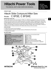
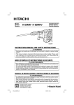
Piston reassembly
Insert the Piston Pin [32] into the D8 hole (marked) of the Piston [33] and the Connecting Rod [34] then pressfit it. Be careful not to protrude the Piston Pin [32] from the outside diameter of the Piston [33]. Move the
crank pin of the Crank Shaft [42] to the bottom dead center and insert the piston ass'y into the Crank Shaft
[42] from the cylinder case of the Cylinder Crank Case [48]. Mount the Retaining Ring for D10 Shaft [41]
using a retaining ring puller.
Piston pin
D8 hole
Mark
Retaining ring
Crank pin portion
Crank shaft
Connecting rod
O-ring
Piston
Cylinder crank case
Fig. 16
Cylinder reassembly
Move the crank pin of the Crank Shaft [42] then move the Piston [33] to the top dead center. Insert the
Cylinder [31] into the Cylinder Crank Case [48].
Cylinder
Piston
Crank pin portion
Cylinder crank case
Crank shaft
Fig. 17
Lubrication
Apply special grease (grease for electric impact drills) to the inner circumference of the Connecting Rod [34],
the O-rings [27] in the Striker [26] and in the Piston [33], the outer circumference of the Retainer Sleeve [16],
the sliding portion of the Second Hammer [20], the Oil Seal [47], Damper (A) [17], Damper (B) [23], Damper
(C) [21], the inner circumference of Sleeve (A) [29], Hammer Holder (B) [22], Hammer Holder (C) [25], and
the end surface of Spring (A) [6]. Seal 53 g of the special grease into the Cylinder Crank Case [48] (the
Connecting Rod [34] side).
Apply Hitachi Motor Grease No. 29 to the Needle Bearing (M661) [54], the pinion portion of the Armature [70],
the Needle Roller D8 x 20 [5] and the Steel Ball D6.35 [11]. Seal 20 g of the Hitachi Motor Grease No. 29 into
the Cylinder Crank Case [48] (the First Gear [53] side).
--- 15 ---