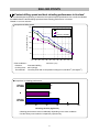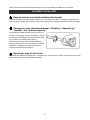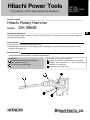
1
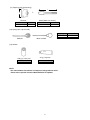
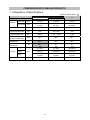
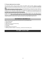
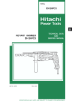
LIST No. DH 38MS: H402 May 2009 PRODUCT NAME Hitachi Rotary Hammer Model DH 38MS D MARKETING OBJECTIVE The new Model DH 38MS is capable of drilling holes of up to 38 mm in diameter into concrete and is compatible with SDS max shank tools. APPLICATIONS x Drilling holes in concrete and drilling anchor holes. x Demolishing and chiseling concrete. Edging, gravel road digging, compacting and tamping, grooving, cutting, stripping and roughing, etc. SELLING POINTS SPECIFICATIONS AND PARTS ARE SUBJECT TO CHANGE FOR IMPROVEMENT. <New features> Fastest drilling speed and best chiseling performance in its class Functional and robust design <Same features as the conventional models> Easy-to-operate with a double-molded side handle Variable lock mechanism for easy working-angle adjustment of chisels, etc. Needle-pin type of slip clutch International Sales Division REMARKS: For more information about HANDLING INSTRUCTIONS, visit our website at: http://www.hitachi-koki.com/manual_view_export/ This TECHNICAL DATA AND SERVICE MANUAL utilizes a symbol to denote the company name and model name of our competitor. The symbol utilized herein is as follows: Competitors Symbol utilized B Company name Model name BOSCH GBH5-38D CONTENTS Page SELLING POINTS ------------------------------------------------------------------------------------------------------------- 1 SPECIFICATIONS ------------------------------------------------------------------------------------------------------------- 3 1. Specifications----------------------------------------------------------------------------------------------------- 3 2. Optional Accessories ------------------------------------------------------------------------------------------- 4 COMPARISON WITH SIMILAR PRODUCTS--------------------------------------------------------------------------- 8 1. Comparison of Specifications ------------------------------------------------------------------------------------------------------- 8 PRECAUTIONS ON SALES PROMOTION ----------------------------------------------------------------------------- 9 1. Safety Instructions ---------------------------------------------------------------------------------------------- 9 REFERENCE MATERIALS-------------------------------------------------------------------------------------------------10 REPAIR GUIDE---------------------------------------------------------------------------------------------------------------- 11 1. Precautions on Disassembly and Reassembly --------------------------------------------------------- 11 STANDARD REPAIR TIME (UNIT) SCHEDULES--------------------------------------------------------------------17 Assembly Diagram for DH 38MS SELLING POINTS Fastest drilling speed and best chiseling performance in its class* We conducted digital engineering to determine the optimal impact specifications. As a result, the Models DH 38MS offers the fastest drilling speed and best chiseling performance in its class. *Based on our own research Comparison of drilling speed 300 HITACHI DH38MS Drilling Speed (mm/min) 250 B HITACHI DH40MR 200 150 100 50 0 16 18 20 22 24 26 28 30 32 34 36 38 Drill Bit Dia. (mm) <Test conditions> Direction: Downward drilling Pushing force: 98 N (10 kgf) Test material: Concrete panel with a compression strength of 2,352 N/cm2 (240 kgf/cm2) Comparison of chiseling performance HITACHI DH 38MS 46 B 44 HITACHI DH 40MR 62 0 20 40 60 80 Chiseling amount (kg/30 min.) Chiseling performance varies considerably depending on the work conditions. Use the factory test results for comparison purposes only. -1- 100 Refer to the Technical Data and Service Manual of the current Model DH 40MR for the following. DH 40MR / List No. E467 Easy-to-operate and double-molded side handle The base material of the side handle is plastic resin. The plastic resin base is integrally molded with soft resin to realize a double-layer structure. As a result, the grip of the soft side handle affords easier operation. Change lever for switching between “Rotation + Hammering,” “Neutral” and “Hammering only” The Models DH 38MS provides three functions; the “rotation + hammering” function (for drilling), “neutral” function (for positioning the tool tip) and “hammering only” function (for chiseling and chipping). These function modes can be easily switched by using the change lever. The tool angle can be easily changed in 12 steps by turning the grip with the change lever positioned at “Neutral.” Needle-pin type of slip clutch The Model DH 38MS is equipped with a needle-pin type of slip clutch for higher slip torque accuracy and enhanced safety (same as the Model DH 40MR). -2- SPECIFICATIONS 1. Specifications Model Capacity - DH 38MS Drill bit (max. dia.): 38 (1-31/64”) mm Core bit (max. dia.): 105 (4-9/64”) Voltage V 110 120 220 230 240 Current A 9.1 8.4 4.6 4.4 4.2 Power input W 950 Materials : Aluminum alloy die casting (Cylinder case, crank case, gear cover) Nylon resin Enclosure (Handle, handle cover, tail cover, crank cover) Polycarbonate resin (Housing) Paint : Green, black, silver metallic green Switch Trigger switch Type of handles D-shaped handle and side handle No load rotation rate min-1 620 Full load impact rate min-1 2,800 Packaging Plastic case * Product 6.4 (14.1) Weight kg (lbs.) Packed 9.5 (20.9) · Plastic case ------------------------------------------------------ 1 Standard accessories · Side handle ------------------------------------------------------ 1 *: Excluding cord and side handle -3- 2. Optional Accessories (1) Drilling work for through-hole drilling (rotation + impact) Drill bit (SDS max shank) L D D mm 16 (5/8”) 19 (3/4”) 22 (7/8”) 25 (1”) 28 (1-1/8”) 32 (1-1/4”) 38 (1-1/2”) L mm Code No. 340 (13-3/8”) 340 (13-3/8”) 320 (12-5/8”) 320 (12-5/8”) 370 (14-9/16”) 370 (14-9/16”) 370 (14-9/16”) 313448 313449 313450 313451 313452 313453 313454 D mm 16 (5/8”) 19 (3/4”) 22 (7/8”) 25 (1”) 28 (1-1/8”) 32 (1-1/4”) 38 (1-1/2”) L mm Code No. 540 (21-1/4”) 540 (21-1/4”) 520 (20-15/32”) 520 (20-15/32”) 570 (22-7/16”) 570 (22-7/16”) 570 (22-7/16”) 313456 313457 313458 313459 313460 313461 313462 (2) Drilling work for anchor holes (rotation + hammering) Drill bit (taper shank) L + D (2) Taper shank adapter (SDS max shank) (1) Drill bit (taper shank) (3) Cotter (1) Drill bit (taper shank) D mm 11.0 (7/16”) 12.3 (15/32”) 14.3 (9/16”) 14.5 (9/16”) 17.5 (11/16”) L mm 100 (4”) 110 (4-5/16”) 110 (4-5/16”) 110 (4-5/16”) 120 (4-3/4”) Code No. 944460 944461 944462 944500 944463 (2) Taper shank adapter Taper dimension Code No. Morse taper No. 1 SDS-plus shank bit adapter + Drill bit (SDS-plus shank) SDS-plus shank bit adapter (SDS max shank) Code No. 313465 -4- 313464 (3) Cotter Code No. 944477 (3) Boring work for large-diameter holes (rotation + hammering) L l + + (Guide plate) D + (3) Core bit shank (SDS max shank) (2) Core bit (1) Center pin (2) Core bit Code No. Guide plate 25 (1”) 955994 29 (1-1/8”) 955995 32 (1-1/4”) 955996 35 (1-3/8”) 955998 38 (1-1/2”) 956000 45 (1-3/4”) 955154 54 (2-1/8”) 955155 64 (2-1/2”) 956002 79 (3-1/8”) 955157 94 (3-11/16”) 956004 105 (4-1/8”) 955159 (1) Center pin (3) Core bit shank (SDS max) l mm Code No. L mm Code No. D mm - - 147 (5-25/32”) 956009 133 (5-1/4”) 955165 300 (11-13/16”) 313466 300 (11-13/16”) 313467 (4) Hole drilling + Chuck adapter (SDS max shank) 13mm drill chuck (13VLD-D) Chuck wrench 13-mm drill chuck (13VLD-D) with chuck wrench Code No. 321813 Chuck adapter Code No. 313468 (5) Chemical anchor holes drilling work (rotation + hammering) + (Socket) Chemical anchor adapter (SDS max shank) Socket square size mm 12.7 (1/2”) 19.0 (3/4”) Code No. 313469 313470 -5- (6) Demolishing work (hammering) Bull point (SDS max shank) L L mm 280 (11”) 450 (15-3/4”) Code No. 313471 313472 (7) Groove digging and edging (hammering) Cold chisel (SDS max shank) L L mm 280 (11”) 450 (15-3/4”) Code No. 313473 313474 (8) Cutting and stripping (cutting asphalt etc.) (hammering) Cutter (SDS max shank) L L mm 400 (15-3/4”) Width mm 50 (2”) (9) Scooping work (hammering) Scoop (SDS max shank) L L mm 400 (15-3/4”) Code No. 313476 (10) Surface roughing work (hammering) L + Bushing tool Code No. 313477 Shank (SDS max shank) L mm 220 (8-21/32”) Code No. 313479 -6- Code No. 313475 (11) Tamping work (hammering) l + L Shank (SDS max shank) Rammer L mm 150 (5-29/32”) Code No. 313478 l mm 220 (8-21/32”) Code No. 313479 (12) Syringe (for chip removal) Bellows Blow-out bulb Syringe Bellows Blow-out bulb (13) Grease 500 g (1.1 lbs.) can Code No. 980927 30 g (1 oz) tube Code No. 981840 NOTE: The code numbers listed above are subject to change without notice. Please refer to periodic Technical News Bulletins for updates -7- Code No. 318085 320859 COMPARISON WITH SIMILAR PRODUCTS 1. Comparison of Specifications (Superior specifications: Maker Model name HITACHI B DH 38MS 38 (1-1/2”) 105 (4-1/8”) DH 40MR 40 (1-9/16”) 105 (4-1/8”) 38 (1-1/2”) 90 (3-17/32”) W 950 950 1,050 Full-load rotation rate min-1 510 240 - 480 340 Full-load impact rate min-1 2,800 1,320 – 2,650 3,000 Full-load vibration level (Tri-axial, measured) No-load noise level (measured) Full-load noise level (measured) m/s2 16.1 18.8 16.1 dB 85.0 81.2 85.7 dB 92.7 92.3 93.3 mm 433 (17-1/64”) 247 (9-3/4”) 103 (4-1/32”) 435 (17-1/8”) 255 (10-3/64”) 104 (4-7/64”) 430 (16-15/16”) 253 (9-31/32”) 102 (4-1/16”) kg (lbs.) 6.4 (14.1) 6.5 (14.3) 5.8 (12.8) Drill bit dia. mm Core bit dia. mm Capacity Power input Length Tool size Height Width Weight* *: Weight does not include the cord and side handle -8- ) PRECAUTIONS ON SALES PROMOTION 1. Safety Instructions In the interest of promoting the safest and most efficient use of the Model DH 38MS Rotary Hammer by all of our customers, it is very important that when conducting a sale that the salesperson carefully ensure that the buyer seriously recognizes the importance of Handling Instructions, and fully understands the precautions listed on the Caution Plate and Nameplate attached to each tool. A. Handling instructions Although every effort is made in each step of design, manufacture, and inspection to provide protection against safety hazards, the dangers inherent in using any electric tool cannot be completely eliminated. Accordingly, the Handling Instructions list general precautions and suggestions on the use of electric power tools, and specific precautions and suggestions on the use of rotary hammers to enhance the safe, efficient use of the tool by the customer. Salespersons must be thoroughly familiar with the contents of the Handling Instructions in order to offer appropriate guidance to customers during sales promotion activities. B. Caution plate Each Model DH 38MS unit is provided with a Caution Plate (shown below) that lists basic safety precautions on its use. Carefully ensure that customers fully understand and follow these precautions before using the tool. [For Australia and New Zealand] [For the USA and Canada] [For China] -9- C. Grease replacement procedures The hammering section and gear change section use different types of grease. There is no need to replenish the grease unless disassembling the tool for repair or in case grease is leaking due to a damaged seal. Special grease is used for the hammering section. After disassembling the hammering section (inside the cylinder case and crankcase), carefully wipe the old grease off the parts and fill the cylinder case and crankcase (on the connecting rod side) with 50 g of grease. Be careful not to overfill the grease as an excessive amount of grease can cause hammering failure. The gear change section (inside the gear cover) uses Hitachi Motor Grease No. 29. The proper amount of grease is 30 g. Never use this special grease for the hammering section in the gear change section. Otherwise, the special grease will leak into the motor section and subsequently cause trouble. Periodically change the grease in the slip clutch. Fully fill the slip clutch with Hitachi Motor Grease No. 29. REFERENCE MATERIALS Refer to the Technical Data and Service Manual for the model indicated below. 1. Torque transmission 2. Striking operation 3. Mechanism to prevent idle hammering 4. Slip clutch mechanism 5. Tool holder 6. Sealing and dust-proof structure 7. Switching between “Rotation + Hammering”, “Neutral” and “Hammering only” DH 40MR / List No. E467 -10- REPAIR GUIDE Be sure to disconnect the power cord plug from the wall outlet before conducting repair. Otherwise, the motor may suddenly run, posing a very dangerous situation. 1. Precautions on Disassembly and Reassembly The [Bold] numbers in the descriptions below correspond to item numbers in the Parts List and exploded view assembly diagram for the Model DH 38MS. Disassembly 1. Disassembly of the tool retainer While pulling the Grip [2] in the arrow direction, remove the Front Cap [1], which is fitted securely. (Forcibly pull the Front Cap [1] to remove it.) Then the Grip [2] can be removed from the Retainer Sleeve [12]. Remove the Stopper Ring [3] by using a retainer ring puller. Then the Needle Holder [4], two Needle Rollers D8 x 20 [13], Retainer Spring [5] and Spring Holder (A) [6] can be removed from the Retainer Sleeve [12] (Fig. 1). Fig. 1 Stopper Ring [3] D8 X 20 Needle Roller [13] Retainer Sleeve [12] Needle Holder [4] Front Cap [1] Grip [2] Spring Holder (A) [6] Retainer Spring [5] 2. Disassembly of the hammering mechanism (a) Second Hammer [15] and Striker [27] Remove the Seal Lock Hex. Socket Hd. Bolt M5 x 16 [67] from the Crank Cover [68]. Remove the Crank Cover [68] from the Crank Case [70]. Remove the Seal Lock Hex. Socket Hd. Bolt M6 x 20 [64] and Seal Lock Hex. Socket Hd. Bolt M6 x 45 [65]. Remove the Gear Cover [80] from the Crank Case [70]. Remove the Slip Clutch Ass'y [49] from the Crank Case [70] beforehand because the Bevel Gear [25] cannot be removed with the Slip Clutch Ass'y [49] remaining in the Crank Case [70]. Remove the Seal Lock Hex. Socket Hd. Bolt M4 x 12 [32] and the Change Lever [33]. Remove the Retaining Ring for D20 Hole [35] securing the Lever Shaft [36] with a retaining ring puller. Remove the Lever Shaft [36] from the Crank Case [70] beforehand because the Bevel Gear [25] cannot be removed with the Lever Shaft [36] remaining in the Crank Case [70]. Remove the Seal Lock Hex. Socket Hd. Bolt (W/Flange) M6 x 25 [8]. Then the Cylinder Case [7], Spring Holder (B) [20], Retainer Sleeve [12] and other parts can be removed from the main body. Remove the Second Hammer [15] from the Retainer Sleeve [12] together with the Damper Holder [18], Damper [17] and Damper Washer [16]. Pull out the Cylinder [19] from the main body together with the Lock Spring [21], Lock Sleeve [22], Clutch Spring [23] and Clutch [24]. Remove the Striker [27] by tapping the end surface of the Cylinder [19] with a plastic hammer (Fig. 2). -11- Fig. 2 Damper [17] Damper Holder [18] Damper Washer [16] Second Hammer [15] Retainer Sleeve [12] Spring Holder (B) [20] Crank Shaft [73] Retaining Ring for D10 Shaft [72] Lock Sleeve [22] Clutch Spring [23] Cylinder Case [7] Retainer Damper [10] Retainer Damper Washer [11] Clutch [24] Striker [27] Lock Spring [21] Cylinder [19] Piston [30] Connecting Rod [31] (b) Piston [30] To remove the Piston [30], use a retaining ring puller to remove the Retaining Ring for the D10 Shaft [72], and then remove the Connecting Rod [31] from the Crank Shaft [73]. (c) First Gear [78] and Crank Shaft [73] Remove the Seal Lock Hex. Socket Hd. Bolt M6 x 45 [65], Seal Lock Hex. Socket Hd. Bolt M6 x 20 [64], Hex. Socket Hd. Bolt (W/Flange) M5 x 16 [67] and Tapping Screw (W/Flange) D5 x 30 (black) [95]. Remove the Crank Case [70] from the Housing Ass'y [48] and Handle [97]. Remove grease from the Piston [30] side and First Gear [78] side of the Crank Case [70]. Use a retaining ring puller to remove the Rataining Ring for D40 Shaft [74] fixing the Ball Bearing 6203DDCMPS2L [75]. At this time, turn the Crank Shaft [73] to expose the hole of the Retaining Ring for the D40 Shaft [74] prior to removal. Use a hand press to press the end face of the Crank Shaft [73], and then remove the First Gear [78] and Crank Shaft [73] from the Crank Case [70] (Fig. 3). Fig. 3 First Gear [78] Crank Case [70] Crank Case [70] Crank Shaft [73] Retaining Ring for D40 Hole [74] Crank Shaft [73] -12- Support (d) Slip Clutch Refer to the Technical Data and Service Manual for the Model DH 40MR (List No. E467) because the slip clutch mechanism is the same as that of the Model DH 40MR. Reassembly Perform reassembly by reversing the order of the disassembly procedure. However, special attention should be given to the following items. 1. Reassembly of the hammering mechanism (a) First Gear [78] and Crank Shaft [73] Press-fit Oil Seal (B) [77] into the Crank Case [70] and mount the O-ring [76]. Then press-fit the Ball Bearing 6203DDCMPS2L [75]. Use a retaining ring puller to mount the Retaining Ring for the D40 Shaft [74]. Press-fit the Crank Shaft [73] into Ball Bearing 6203DDCMPS2L [75]. Put the Feather Key 3 x 3 x 8 [51] into the groove of the Crank Shaft [73] and then press-fit the First Gear [78] with a suitable jig, while holding the flat portion of the Crank Shaft [73] with a steel bar. Before press-fitting, make sure that the Feather Key 3 x 3 x 8 [51] fits into the key groove of the First Gear [78] (Fig. 4). BB.6203DDCMPS2L [75] Fig. 4 First Gear [78] 3 x 3 x 8 Key [51] Support Oil seal (B) [77] O-ring [76] Crank Shaft [73] Steel Bar Retaining Ring for D40 Hole (b) Piston [30] Insert the Connecting Rod [31] into the Piston [30] and then insert the Piston Pin [29] into the 8-mm dia. hole (on the marked side) of the Piston [30]. (Be careful not to protrude the Piston Pin [29] from the outer diameter of the Piston [30].) Mount the O-ring [28] to the Piston [30] to complete the piston ass'y. Move the crank pin of the Crank Shaft [73] to the bottom dead center, and then mount the piston ass'y to the Crank Shaft [73] from the Cylinder Case [7] side of the Crank Case [70]. Use a retaining ring puller to mount the Retaining Ring for the D10 Shaft [72] (Fig. 5). Fig. 5 Mark Piston Pin [29] O-Ring [28] Retaining Ring for D10 Shaft [72] Piston[30] Connecting Rod [31] Piston Ass’y Crank Case [70] -13- Crank Shaft [73] (c) Cylinder [19] and Retainer Sleeve [12] Mount the Retainer Damper Washer [11] and Retainer Damper [10] to the Retainer Sleeve [12] in this order by aligning the rounded portion of the Retainer Damper Washer [11] with the rounded portion of the Retainer Sleeve [12]. Mount the Second Hammer [15] (with O-ring (C) [14] mounted), Damper Washer [16], Damper [17] and Damper Holder [18] in this order by aligning the rounded portion of the Damper Washer [16] with the rounded portion of the Second Hammer [15]. Insert the assembly of the Retainer Sleeve [12] into the Cylinder Case [7], and then insert Spring Holder (B) [20] into the Cylinder Case [7]. Insert the Striker [27] (with the O-ring [28] mounted) into the Cylinder [19]. Mount the Clutch Spring [23], Clutch [24], Bevel Gear [25] and Thrust Washer [26] to the Cylinder [19], and then insert this Cylinder [19] ass'y into the Crank Case [70]. Insert the Lock Sleeve [22] into the Crank Case [70] by aligning the spline groove at the inner circumference of the Crank Case [70] with the spline of the Lock Sleeve [22]. Put the Lock Spring [21] on the Lock Sleeve [22]. Finally put the Cylinder Case [7] (with the Retainer Sleeve [12] mounted) and the Crank Case [70] (with the Cylinder [19] mounted) together by meshing the claw of the Retainer Sleeve [12] with the groove of the Cylinder [19] (Fig. 6). Fig. 6 Damper Holder [18] Damper Washer [16] Cylinder Case [7] Spring Holder (B) [20] Damper [17] Second Hammer [15] Retainer Sleeve [12] Bevel Gear [25] Retainer Damper [10] Clutch Spring [23] Retainer Damper Washer [11] Lock Sleeve [22] Thrust Washer [26] Clutch [24] Striker [27] Cylinder [19] Lock Spring [21] Crank Case [70] (d) Slip Clutch Refer to the Technical Data and Service Manual for the Model DH 40MR (List No. E467) because the slip clutch mechanism is the same as that of the Model DH 40MR. -14- 2. Application of lubricant • Filling special grease (for the hammer and hammer drill) In the Cylinder Case [7]: 15 g Connecting Rod [31] side in the Crank Case [70]: 50 g • Application of special grease (for the hammer and hammer drill) Apply special grease to the inner circumferences of the Cylinder [19] and Connecting Rod [31], the sliding portion of the Second Hammer [15], the O-ring (C) [14] wound around the Second Hammer [15], the sliding portion of the Striker [27], the O-ring [28] wound around the Striker [27] and Piston [30], the lip portions at the inner circumference of Oil Seal (A) [53] and Oil Seal (B) [77], the inner and outer circumferences of the Bevel Gear [25], the inner circumference of metal in the Cylinder Case [7], and the lip portions at the inner circumference of oil seals in the Cylinder Case [7], Damper [17] and Retainer Damper [10]. • Filling Hitachi Motor Grease No. 29 First Gear [78] side and Gear Cover [80] side in the Crank Case [70]: 30 g in total • Application of Hitachi Motor Grease No. 29 Pinion portions of the Needle Bearing M661 [79], Armature Ass'y [43] and Needle Roller D8 x 20 [13] 3. Tightening torque Apply screw locking agent TB1401 to all hex. socket head bolts M4, M5 and M6. NOTE: Be sure to apply screw locking agent (Three Bond TB1401) to the threads during reassembly. Otherwise, any bolts loosened due to vibration may damage the tool body. M6 • Seal Lock Hex. Socket Hd. Bolt M6 x 45 [65] (For mounting the housing) -------------------------------- 9.8 ± 0.98 N•m (100 ± 10 kgf•cm) • Seal Lock Hex. Socket Hd. Bolt M6 x 20 [64] (For mounting the gear cover) ----------------------------- + 20 9.8 + 1.96 N•m (100 0 kgf•cm) 0 • Hex. Socket Hd. Bolt (W/Flange) M6 x 25 [8] (For mounting the cylinder case) ------------------------- M5 9.8 + 1.96 0 + 20 N•m (100 0 kgf•cm) • Hex. Socket Hd. Bolt (W/Flange) M5 x 16 [67] (For mounting the crank cover) --------------------------- 7.84 + 1.96 0 + 20 N•m (80 0 kgf•cm) • Hex. Socket Hd. Bolt (W/Flange) M5 x 16 [67] (For mounting the handle) ---------------------------------- M4 5.88 + 1.96 0 + 20 N•m (60 0 kgf•cm) • Seal Lock Hex. Socket Hd. Bolt M4 x 12 [32] (For mounting the change lever) -------------------------- 4.41 ± 0.49 N•m (45 ± 5 kgf•cm) • Tapping Screw (W/Flange) D5 ------------------------------ 2.94± 0.49 N•m (30 ± 5 kgf•cm) • Tapping Screw (W/Flange) D4 ------------------------------ 1.96± 0.49 N•m (20 ± 5 kgf•cm) -15- 4. Internal wiring (1) Wiring diagram for products without a noise suppressor Stator ass’y Armature ass’y Switch (C) (1P screw type) w/o lock Plug A Connector or Pillar Terminal (2) Wiring diagram for products with a noise suppressor Stator ass’y Armature ass’y Switch (C) (1P screw type) w/o lock Connector Noise A Plug Suppressor Connector Pillar Terminal 5. Insulation tests Upon the completion of disassembly and repair, measure the insulation resistance and dielectric strength. Insulation resistance: 7M or more using a 500 VDC megohm tester Dielectric strength: 4,000 VAC/minute, with no abnormalities (220 to 240 V) (110 V for U.K. products) 2,500 VAC/minute, with no abnormalities (110 to 127 V) (Except for U.K. products) 6. No-load current value After no-load operation for 30 minutes, the no-load current values should be as follows: Voltage (V) 110 120 220 230 240 Current (A) max. 6.4 5.9 3.2 3.1 2.9 -16- STANDARD REPAIR TIME (UNIT) SCHEDULES MODEL Variable Fixed 10 20 30 40 50 60 Work Flow DH 38MS Housing Ass'y Stator Ass'y Handle Cover Switch (C) Cord Cord Armor Gear Cover Needle Bearing Tail Cover Armature Ass’y Ball Bearing (6201 DDCMPS2L) Dust Washer (B) Ball Bearing (608 VVC2PS2L) Crank Cover General assembly Handle Change Lever Lever Holder Lever Shaft Crank Shaft Ball Bearing (6203 DDCMPS2L) Oil Seal (B) First Gear Slip Clutch Front Cap Grip Needle Holder Ass'y Bevel Pinion Oil Seal (A) Ball Bearing (6002 DDCMPS2L) Washer (A) Gear Holder Second Gear Ball Bearing (629 VVC2PS2L) Cylinder Case Retainer Damper Retainer Sleeve Second Hammer Damper Cylinder Lock Sleeve Clutch Striker O-Ring -17- Bevel Gear Piston Connecting Rod Crank Case LIST NO. H402 ROTARY HAMMER Model DH 38MS 2009㨯5㨯26 (E1) 1 66 67 501 2 66 3 4 68 65 5 6 69 7 37 8 36 35 9 10 51 33 11 70 50 34 112 32 52 38 12 49 71 53 13 39 54 40 55 14 41 15 16 73 56 51 42 17 72 57 74 18 19 58 43 75 59 20 76 21 60 77 44 22 61 23 45 24 78 62 79 25 63 46 26 27 80 47 28 64 29 48 30 31 97 96 83 82 85 84 67 81 104 90 103 105 89 88 87 110 91 99 92 100 101 107 108 111 94 Rev.1 95 102 93 86 106 98 ᒻޓޓޓฬ 95 DH38MS ዤޓᐲ 30% 109 ࿑⇟ޓޓޓ TU01680 PARTS ITEM NO. DH 38MS CODE NO. DESCRIPTION NO. USED 1 331-542 FRONT CAP 1 2 331-541 GRIP 1 3 331-540 STOPPER RING 1 4 331-539 NEEDLE HOLDER 1 5 331-538 RETAINER SPRING 1 6 331-537 SPRING HOLDER (A) 1 7 331-530 CYLINDER CASE 1 8 991-712 HEX. SOCKET HD. BOLT (W/FLANGE) M6 X 25 4 9 956-996 O-RING (1AS-60) 1 10 331-531 RETAINER DAMPER 1 11 331-532 RETAINER DAMPER WASHER 1 12 331-524 RETAINER SLEEVE 1 13 331-536 NEEDLE ROLLER D8 X 20 2 14 313-396 O-RING (C) 1 15 331-525 SECOND HAMMER 1 16 331-224 DAMPER WASHER 1 17 321-835 DAMPER 1 18 331-225 DAMPER HOLDER 1 19 331-526 CYLINDER 1 20 331-533 SPRING HOLDER (B) 1 21 331-534 LOCK SPRING 1 22 331-535 LOCK SLEEVE 1 23 331-527 CLUTCH SPRING 1 24 331-528 CLUTCH 1 25 331-529 BEVEL GEAR 1 26 331-234 THRUST WASHER 1 27 331-235 STRIKER 1 28 986-104 O-RING 2 29 331-221 PISTON PIN 1 30 326-369 PISTON 1 31 321-285 CONNECTING ROD 1 32 983-162 SEAL LOCK HEX. SOCKET HD. BOLT M4 X 12 1 33 331-545 CHANGE LEVER 1 34 331-544 LEVER HOLDER 1 35 311-229 RETAINING RING FOR D20 HOLE 1 36 331-543 LEVER SHAFT 1 37 873-095 O-RING (P-16) 1 38 331-548 PIN D2 X 10 1 39 331-546 LEVER SPRING 1 40 321-311 PUSHING BUTTON 1 41 620-1DD BALL BEARING 6201DDCMPS2L 1 DUST WASHER (B) REMARKS 42 325-003 * 43 360-875C ARMATURE 110V * 43 360-875U ARMATURE ASS'Y 120V 1 * 43 360-875E ARMATURE 220V-230V 1 * 43 360-875F ARMATURE 240V 1 44 331-252 FAN GUIDE 1 45 953-174 HEX. HD. TAPPING SCREW D5 X 55 2 * 46 340-753C STATOR ASS'Y 110V 1 INCLUD. 47 * 46 340-753G STATOR ASS'Y 110V 1 INCLUD. 47 FOR VEN -2- 1 1 *ALTERNATIVE PARTS INCLUD. 41, 42, 91, 92 05 - 09 PARTS ITEM NO. DH 38MS CODE NO. DESCRIPTION NO. USED * 46 340-753D STATOR ASS'Y 120V * 46 340-753E STATOR ASS'Y 220V-230V 1 INCLUD. 47 * 46 340-753H STATOR ASS'Y 220V-230V 1 INCLUD. 47 FOR THA, INA, SIN, IND * 46 340-753J STATOR ASS'Y 240V 1 INCLUD. 47 * 46 340-753F STATOR ASS'Y 240V 1 INCLUD. 47 FOR AUS 47 930-703 BRUSH TERMINAL 2 48 331-251 HOUSING ASS'Y 1 INCLUD. 89, 90 49 331-210 SLIP CLUTCH ASS'Y 1 INCLUD. 50-52, 54-62 50 331-211 BEVEL PINION 1 51 944-109 FEATHER KEY 3 X 3 X 8 2 52 331-212 COLLAR 1 53 313-050 OIL SEAL (A) 1 54 600-2DD BALL BEARING 6002DDCMPS2L 1 55 331-213 WASHER 1 56 331-214 WASHER (A) 1 57 321-281 GEAR HOLDER 1 58 331-218 SPRING (C) 10 59 331-217 NEEDLE 10 60 331-215 SECOND GEAR 1 61 331-219 SPACER 1 62 629-VVM BALL BEARING 629VVC2PS2L 1 63 331-220 BEARING WASHER (C) 1 64 992-803 SEAL LOCK HEX. SOCKET HD. BOLT M6 X 20 2 65 986-940 66 1 REMARKS SEAL LOCK HEX. SOCKET HD. BOLT M6 X 45 4 HITACHI LABEL 2 67 994-192 HEX. SOCKET HD. BOLT (W/FLANGE) M5 X 16 6 68 331-245 CRANK COVER 1 69 878-713 CYLINDER O-RING (B) 1 70 331-523 CRANK CASE 1 71 331-549 SEAL PACKING 1 72 939-540 RETAINING RING FOR D10 SHAFT (10 PCS.) 1 73 331-208 CRANK SHAFT 1 74 948-391 RETAINING RING FOR D40 HOLE 1 75 620-3DD BALL BEARING 6203DDCMPS2L 1 76 996-363 O-RING (S-40) 1 77 321-274 OIL SEAL (B) 1 78 331-209 FIRST GEAR 1 79 939-299 NEEDLE BEARING (M661) 1 80 331-253 GEAR COVER 1 81 307-947 WING BOLT M6 X 12 1 82 331-248 MOUNT 1 83 949-556 NUT M6 (10 PCS.) 1 84 331-247 HANDLE BOLT 1 85 331-246 BAND 1 86 330-209 SIDE HANDLE 1 87 945-161 BRUSH CAP 2 88 999-043 CARBON BRUSH (1 PAIR) 2 89 958-900 BRUSH HOLDER 2 90 938-477 HEX. SOCKET SET SCREW M5 X 8 2 91 982-631 WASHER (A) 1 05 - 09 *ALTERNATIVE PARTS INCLUD. 47 -3- PARTS ITEM NO. * DH 38MS CODE NO. DESCRIPTION NO. USED 92 608-VVM BALL BEARING 608VVC2PS2L 1 93 331-254 BEARING HOLDER 1 94 331-202 TAIL COVER 1 95 302-089 TAPPING SCREW (W/FLANGE) D5 X 20 (BLACK) 4 96 331-203 NOISE SUPPRESSOR 1 REMARKS EXCEPT FOR VEN, THA, INA, SIN, KUW, USA, CAN, MEX, IND 97 331-204 HANDLE 1 * 98 330-216 INTERNAL WIRE 270L 1 EXCEPT FOR VEN, THA, INA, SIN, * 99 959-141 CONNECTOR 50092 (10 PCS.) 1 EXCEPT FOR USA, CAN, MEX NAME PLATE 1 KUW, USA, CAN, MEX, IND 100 * 101 500-390Z CORD 1 (CORD ARMOR D8.2) * 101 500-239Z CORD 1 (CORD ARMOR D10.7) FOR VEN, THA * 101 500-424Z CORD 1 (CORD ARMOR D8.2) FOR SIN, KUW * 101 500-235Z CORD 1 (CORD ARMOR D8.2) FOR INA, IND * 101 500-439Z CORD 1 (CORD ARMOR D8.2) FOR, NZL, AUS * 101 500-434Z CORD 1 (CORD ARMOR D8.2) FOR USA, CAN, MEX * 101 500-446Z CORD 1 (CORD ARMOR D8.2) FOR GBR (230V) * 101 500-454Z CORD 1 (CORD ARMOR D8.2) FOR GBR (110V) * 101 500-391Z CORD 1 (CORD ARMOR D8.2) FOR SUI * 101 500-457Z CORD 1 (CORD ARMOR D10.7) FOR CHN * 101 500-477Z CORD 1 (CORD ARMOR D10.7) FOR TPE * 101 500-475Z CORD 1 (CORD ARMOR D8.2) FOR KOR * 102 958-049 CORD ARMOR D8.2 1 * 102 940-778 CORD ARMOR D10.7 1 * 103 981-974 INTERNAL WIRE 1 104 313-093 SWITCH (C) (2P SCREW TYPE W/O LOCK) 1 EXCEPT FOR VEN, THA, INA, SIN, KUW, USA, CAN, MEX, IND * 105 938-307 PILLAR TERMINAL 1 EXCEPT FOR VEN, THA, INA, SIN, KUW, IND * 106 959-141 CONNECTOR 50092 (10 PCS.) 1 EXCEPT FOR USA, CAN, MEX 107 960-266 CORD CLIP 1 108 984-750 TAPPING SCREW (W/FLANGE) D4 X 16 2 109 331-205 HANDLE COVER 1 110 307-028 TAPPING SCREW (W/FLANGE) D4 X 25 (BLACK) 2 111 331-547 DUST SEAL 1 112 331-550 WASHER (FW) 1 STANDARD ACCESSORIES ITEM NO. 501 -4- CODE NO. 331-206 DESCRIPTION CASE NO. USED REMARKS 1 *ALTERNATIVE PARTS Printed in Japan 05 - 09 (090526N)