1
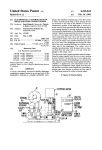
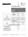
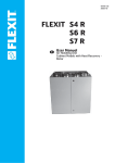
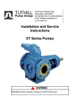
SERVICE MANUAL
SECTION 16, Page 511
April, 1984
r
Supersedes
April, 1978
LOUIS ALLIS PACEMAKER MOTOR
C317
GENERAL PURPOSE SQUIRREL CAGE MOTORS
DRIP-PROOF HORIZONTAL
FRAMES 180 THROUGH 440
Drip-Proof Pacemaker 180-250 Frame
RECEIPT OF SHIPMENT
When your equipment arrives, it should be checked immediately to see
that all components have been received and that there is no evidence
of damage in shipment .
In the event the complete assembly has not been received, or arrives in
a damaged condition you should without delay notify the carrier who
handled the shipment and the nearest Louis Allis Sales Office .
Drip-Proof Pacemaker 280-440 Frame
When mounting, we recommend the use of slotted shims as it may be
necessary to remove or add shims when aligning shafts . The use of
proper shims inserted under each mounting foot will prevent distortion
of the housing when the mounting bolts are secured . The following
procedure is recommended when mounting the motor .
1 . Add shims under the lowest mounting foot and tighten mounting
foot bolt .
2 . Insert feeler gauges under the other mounting feet to determine
amount of shims required .
STORAGE
If the equipment is not put into immediate use it should be stored in a
clean, dry location . For long periods of storage, especially where
moisture or dust is prevalent, the equipment should be covered to
protect it from corrosion .
3 . Insert required shims under each mounting foot and tighten
mounting bolts .
4 . Use a small number of thick shims rather than a large number of
thin shims .
5 . Measure the alignment .
LOCATION
In selecting a location for the unit, first consideration should be given
to ventilation . It should be far enough from walls or other objects to
permit a free passage of air .
The motor should never be placed in a room with a hazardous process,
or where flammable gases or combustible material may be present
unless it is specifically designed for this type of service .
INSTALLING COUPLING AND SHEAVES
The .flexible coupling or sheave should be heated in oil before
installation and slid into position on the shaft or installed with a
pushing device .
MOUNTING
The motor should be securely mounted on a bed plate, base or
platform that is rigid enough to prevent any vibration of the unit and
also prevent transfer of vibration to the unit . The base must not
impose bending or twisting strains on the housing .
COPYRIGHT © 1984 LOUIS ALLIS
PRICES AND OTHER DATA SUBJECT
TO CHANGE WITHOUT NOTICE .
http://legacy.library.ucsf.edu/tid/wtk23e00/pdf
WARNING : DO NOT DRIVE OR FORCE COUPLINGS OR
SHEAVES ONTO THE SHAFT . DAMAGE TO BEARINGS MAY
RESULT . REFER TO THE COUPLING MANUFACTURER'S
INSTRUCTIONS FOR THE PROPER INSTALLATION PROCEDURE'.
LOUIS ALLIS
Mibrdaukee W Scons n 53201
2030050365
SERVICE MANUAL
SE~CTION 16, Page 542
April, 1984
r
Supersedes
Febcua<y, 198I
ALIGNMENT (Direct Connected)
STRAIGHT EDGE
ANGULAR MISALIGNMENT and RUN-OUT between direct
connected shafts will cause increased bearing loads and vibration even
when the connection is made by means of a flexible coupling .
LOAD
To check for ANGULAR MISALIGNMENT, clamp the dial indicator
to one coupling hub and place the finger, or button of the indicator
against the finished face of the other hub as shown in the diagram
below .
MOTOR
Aligning Belted Drive
TEMPERATURE
The ambient temperature of the air surrounding the motor should not
exceed 40°C or 104°F unless the motor has been especially designed
for high ambient temperature applications . The free flow of air
around the motor should not be obstructed .
COUPLING HUBS
;.
Checking for Angular Nfrsalignment
Rotate both shafts simultaneously, keeping the indicator button at the
reference mark on the coupling hub, and note the reading on the
indicator dial at each one-quarter revolution .
ANGULAR MISALIGNMENT OF THE SHAFTS MUST NOT
EXCEED A TOTAL INDICATOR READING OF .002 INCH FOR
EACH INCH OF DIAMETER OF THE COUPLING HUB .
After the shafts have been checked for angular misalignment and are
parallel within the limits specified in the preceding paragraph, check
the shaft for RUN-OUT to assure concentricity of the shaft . Clamp
the indicator to one coupling hub and place the indicator button on
the machined diameter of the other hub as shown in the diagram
below .
NEVER ATTEMPT TO MEASURE THE TEMPERATURE RISE OF
A MOTOR BY HAND . Temperature rise MUST be measured by
thermometer, resistance, or by imbedded detector or thermocouple .
WIRING
Before starting the motor, check the nameplate to insure that the
correct power supply (voltage frequency, and phase) is being used
and that the motor is connected according to the connection
diagram on the nameplate .
Be sure that the motor is connected for the correct rotation . Before
connecting the driven machine, energize the motor and check the
rotation .
THERMOSTATS
Standard Louis Allis Pacemaker motors are equipped with normally
closed winding thermostats as required to comply with Underwriters Laboratories regulations on motor surface temperature . Thermostats are located in the winding, and the leads are marked X1,
X2 . The leads are to be connected in the control circuit so that
when the thermoguard is activated the power source to the motor will
be disconnected . Class I Group D units do not require thermostats .
OPERATION
COUPLING HUBS
Checking RUN-OUT of Directly Connected Shafts
Rotate both shafts simultaneously, keeping the indicator button at
the reference mark on the hub and note the reading on the indicator
dial at each one-quarter revolution .
TOTAL RUN-OUT BETWEEN HUBS SHOULD NOT EXCEED .002
INCH .
ALIGNMENT (Belted)
Aligning a belted drive is much simpler than aligning a direct coupling
drive . To check alignment, place a straight edge across the faces of the
driver and driven sheaves . If properly aligned, the straight edge will
contact both sheave faces squarely . The figure below shows the
correct alignment of sheaves .
LOUIS ALLIS
M,WaUkeE WI$CQ(15 :r1 7Z?(1!
http://legacy.library.ucsf.edu/tid/wtk23e00/pdf
Alternating current motors shall operate successfully at rated load
and frequency with voltages not more than 10% above or below
nameplate ratings . Motors shall operate successfully at rated load
and voltage with frequency variations not more than 5% above or
below the rated frequency . Motors shall also operate successfully
at rated loads with combined variations in voltage and frequency not
more than 10r/o above or below the rated voltage and frequency
provided the frequency variation does not exceeed 5% . Motors
operated with the above listed conditions are not necessarily in
accordance with the guarantees for standard conditions .
REGREASING
Lubrication for Motor With Grease Fittings
Under normal operating conditions, it is only necessary to regrease
a ball bearing motor every two to six years, depending upon the
motor speed and operating conditions . A sound greasing procedure
should be followed when regreasing a motor for it has been determined that THE GREATEST CAUSE OF BEARING FAILURE IS
OVER GREASING RATHER THAN UNDER GREASING .
PRICES AND OTHER DATA SUBJECT
TO CHANGE WITHOUT NOTICE .
2030050366
SERVICE MANUAL
SECTION 16, Page 543
Aprit, 1984
Supersedes
February, 1981
Nhen regreasing the following steps shotdd be followed :
Lubrication for Motor Without Grease Fittings
1 . Clean the exterior of the motor .
Bearings are factory lubricated for normal life . In the case of double
shielded bearing the grease provided is that which is in the bearing .
2 . Remove both the grease plug and relief plug (if supplied) .
R'hen regreasing the following steps should be taken .
3 . If grease has hardened, run a rod or wire a short distance into
chamber to break grease . In severe conditions, run motor until
bearing chamber becomes heated .
l . Remove fan guard
2 . Remove fan .
3 . Remove front and back cartridge bolts .
4 . Regrease motor with low pressure grease gun .
4 . Remove bearing brackets .
5 . For optimum operation, the bearing chamber should be threequarters full of grease .
6 . Operate motor for minimum of one hour .
7 . Replace grease plugs .
5 . If original bearing is to be relubricated, remove shield opposite
rotor . Do not replace . Flush old grease from bearing with suitable
solvent . Lubricate bearing and add additional grease to bearing
chamber . Chamber should be three-quarters full of grease .
5a . An alternate method is to replace old bearing with new double shield
prelubricated bearing .
NOTE : If the bearings are rough, the motor should be disassembled
and the bearings replaced . Repack the bearings and bearing chamber
with enough grease so that the bearing chamber of the assembled
motor will be approximately three-quarters full .
6 . Bearing to be lubricated with recommended grease .
7 . Reassemble motor .
RECOMMENDED BALL BEARING GREASES FOR NORMAL CONDITIONS*
It is recommended that these greases or their equivalents be used in Louis Allis motors .
Company
NORMAL
Ambient Temperature
-20°F to 105°F
HIGH
Ambient Temperature
0 to 150°F
Chevron Oil Co .
Shell Oil Co .
SRI No . 2
Dolium R
SRI No . 2
Dolium R
Shell Oil Co .
Texaco
Darina No . 2
Premium RB
Darina No . 2
Premium RB
Texaco
Mobil
AFB No . 2
Mobilux No . 2
AFB No . 2
Mobiltemp SHC 32
Mobil
Mobilgrease 28
Mobilgrease 28
Gulf Oil
Gulf Crown No . 2
Gulf Crown No . 2
Exxon
Unirex N2
Unirex N2
*NORMAL conditions are considered to include most ambient
atmospheres and operation requirements . SEVERE conditions include the following :
RECOMMENDED REGREASING
SCHEDULE FOR BALL BEARINGS"
Extreme dust, dirt or other atmospheric contaminants .
Direct exposure to moisture beyond normal atmospheric
humidity .
Shock, vibration or other loading beyond rated .
Extremes of operation cycle such as long shutdown, frequent
starting or reversing .
Approximate Hours of Operation
Motor Speed
1200 & Below
Normal Conditions
Severe Conditions
6000 - 8000
3000 - 4000
1800
3000-4000
1400-2000
3600
1500 - 2000
750 -1000
For lubrication recommendations covering above SEVERE
conditions refer to special lube instructions furhished, or
consult nearest Louis Allis Sales Office .
For roller bearings refer to special lube instructions or
Louis Allis Sales Office .
PRICES AND OTHER DATA SUBJECT
TO CHANGE WITHOUT NOTICE .
http://legacy.library.ucsf.edu/tid/wtk23e00/pdf
**For roller bearings 1800 RPM and below and in the absence
of other instructions, it is recommended that the above hours
be reduced to 1/3 listed values .
LOUIS ALLIS
MiIwaukeE WtSCOns,n 5320,
2030050367
SERVICE MANUAL
aSECTION 16, Page 514
Aprtl, 1984
Supersedes
Ap~N, 1978
LOUIS ALLIS PACEMAKER MOTOR
,
Drip-Proof Pacemaker 140-250 Frame
4 . Rotor
7.
8.
9.
10 .
5 . Front Bearing
11 . Back Bearing Bracket Bolt
17 . Conduit Box Gasket
6 . End Cover
12 . Back Air Deflector
18 . Housing
1 . Front Bearing Bracket
2 . Front Air Deflector
3 . Fan
Stator
Screens
Conduit Box
Lifting Lug (Not Included 140-250)
13 . Back Bearing
14 . Back Bearing Lock Nut with Washer
15 . Shaft
16 . Back Bearing Bracket
NOTE : Special motors such as flange mounted motors and/or motors with special shafts may not follow the above parts list
exactly . However, construction details will be similar to the above and parts lists are available upon request .
When ordering repair parts, always give the serial number of the motor being serviced, the part name and number and furnish
complete nameplate data .
Drip-Proof Pacemaker 280-440 Frame
LOUIS ALLIS
Milwaukee W SConsin 53201
http://legacy.library.ucsf.edu/tid/wtk23e00/pdf
PRICES AND OTHER DATA SUBJECT
TO CHANGE WITHOUT NOTICE .
2030050368