1
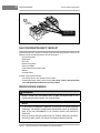
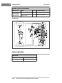
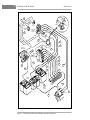
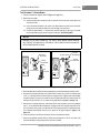
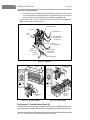
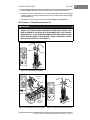
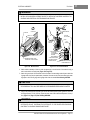
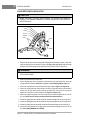
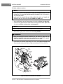
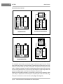
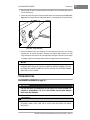
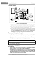
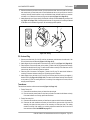
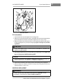
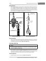
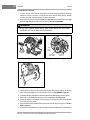
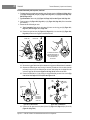
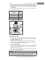
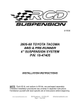
14
ACCU-POWER BATTERY CHARGER
Charger Repairs
Checking Proper Operation of Electronic Timer Kit
1. With the DC plug disconnected from the receptacle, plug the AC cord into an outlet. The relay on the
electronic timer kit should not close. A multimeter set to 200 volts DC and connected across the DC
plug should indicate zero volts. The transformer should not hum.
2. Unplug the AC cord from its outlet and connect the DC plug to the receptacle. The relay, located next to
the electronic timer kit, should close with an audible “click” after a two to five second delay.
3. If the electronic timer kit does not operate as in step one or two above, refer to the wiring diagram (Figure 14-2, Page 14-2) and make sure the charger is wired correctly. If the electronic timer kit operates
properly, the charger is ready for use. Always monitor the first charge cycle to verify the charger is turning OFF properly.
CAPACITOR
MOUNTING BAND SCREW
CAPACITOR
Figure 14-17 Capacitor
Capacitor Removal
1.
2.
3.
4.
Remove the charger cover. See DANGER on page 14-5.
Loosen the mounting band screw (Figure 14-17, Page 14-18). See CAUTION on page 14-10.
Remove the connectors from the capacitor terminals.
Pull the capacitor out of the band.
Capacitor Installation
1. Route the capacitor wires through the band and then slide the capacitor into the band.
2. Tighten the mounting band screw.
3. Connect the terminal connectors to the capacitor terminals.
4. Install the charger cover and check the charger for proper operation.
HEAT SINK ASSEMBLY
Heat Sink Assembly Removal
1. Remove the charger cover. See DANGER on page 14-5.
2. Disconnect both secondary transformer leads (tan) from the heat sink assembly.
3. Disconnect the red, green, and white wires from the heat sink assembly.
4. Remove the nuts and bolts which secure the heat sink assembly to the case.
Page 14-18 1998/1999 V-Glide 36-Volt Vehicle Maintenance and Service Supplement