1
Oracle ZFS Storage Appliance Customer
Service Manual, Release 2013.1.3.0
®
For ZS4-4, ZS3-x, 7x20 Controllers, and DE2-24, Sun Disk
Shelves
Part No: E55850-01
December 2014
Copyright © 2009, 2014, Oracle and/or its affiliates. All rights reserved.
This software and related documentation are provided under a license agreement containing restrictions on use and disclosure and are protected by intellectual property laws. Except
as expressly permitted in your license agreement or allowed by law, you may not use, copy, reproduce, translate, broadcast, modify, license, transmit, distribute, exhibit, perform,
publish, or display any part, in any form, or by any means. Reverse engineering, disassembly, or decompilation of this software, unless required by law for interoperability, is
prohibited.
The information contained herein is subject to change without notice and is not warranted to be error-free. If you find any errors, please report them to us in writing.
If this is software or related documentation that is delivered to the U.S. Government or anyone licensing it on behalf of the U.S. Government, the following notice is applicable:
U.S. GOVERNMENT END USERS. Oracle programs, including any operating system, integrated software, any programs installed on the hardware, and/or documentation, delivered
to U.S. Government end users are "commercial computer software" pursuant to the applicable Federal Acquisition Regulation and agency-specific supplemental regulations. As
such, use, duplication, disclosure, modification, and adaptation of the programs, including any operating system, integrated software, any programs installed on the hardware, and/or
documentation, shall be subject to license terms and license restrictions applicable to the programs. No other rights are granted to the U.S. Government.
This software or hardware is developed for general use in a variety of information management applications. It is not developed or intended for use in any inherently dangerous
applications, including applications that may create a risk of personal injury. If you use this software or hardware in dangerous applications, then you shall be responsible to take all
appropriate fail-safe, backup, redundancy, and other measures to ensure its safe use. Oracle Corporation and its affiliates disclaim any liability for any damages caused by use of this
software or hardware in dangerous applications.
Oracle and Java are registered trademarks of Oracle and/or its affiliates. Other names may be trademarks of their respective owners.
Intel and Intel Xeon are trademarks or registered trademarks of Intel Corporation. All SPARC trademarks are used under license and are trademarks or registered trademarks of
SPARC International, Inc. AMD, Opteron, the AMD logo, and the AMD Opteron logo are trademarks or registered trademarks of Advanced Micro Devices. UNIX is a registered
trademark of The Open Group.
This software or hardware and documentation may provide access to or information on content, products, and services from third parties. Oracle Corporation and its affiliates are
not responsible for and expressly disclaim all warranties of any kind with respect to third-party content, products, and services. Oracle Corporation and its affiliates will not be
responsible for any loss, costs, or damages incurred due to your access to or use of third-party content, products, or services.
Copyright © 2009, 2014, Oracle et/ou ses affiliés. Tous droits réservés.
Ce logiciel et la documentation qui l’accompagne sont protégés par les lois sur la propriété intellectuelle. Ils sont concédés sous licence et soumis à des restrictions d’utilisation et
de divulgation. Sauf disposition de votre contrat de licence ou de la loi, vous ne pouvez pas copier, reproduire, traduire, diffuser, modifier, breveter, transmettre, distribuer, exposer,
exécuter, publier ou afficher le logiciel, même partiellement, sous quelque forme et par quelque procédé que ce soit. Par ailleurs, il est interdit de procéder à toute ingénierie inverse
du logiciel, de le désassembler ou de le décompiler, excepté à des fins d’interopérabilité avec des logiciels tiers ou tel que prescrit par la loi.
Les informations fournies dans ce document sont susceptibles de modification sans préavis. Par ailleurs, Oracle Corporation ne garantit pas qu’elles soient exemptes d’erreurs et vous
invite, le cas échéant, à lui en faire part par écrit.
Si ce logiciel, ou la documentation qui l’accompagne, est concédé sous licence au Gouvernement des Etats-Unis, ou à toute entité qui délivre la licence de ce logiciel ou l’utilise pour
le compte du Gouvernement des Etats-Unis, la notice suivante s’applique:
U.S. GOVERNMENT END USERS. Oracle programs, including any operating system, integrated software, any programs installed on the hardware, and/or documentation, delivered
to U.S. Government end users are "commercial computer software" pursuant to the applicable Federal Acquisition Regulation and agency-specific supplemental regulations. As
such, use, duplication, disclosure, modification, and adaptation of the programs, including any operating system, integrated software, any programs installed on the hardware, and/or
documentation, shall be subject to license terms and license restrictions applicable to the programs. No other rights are granted to the U.S. Government.
Ce logiciel ou matériel a été développé pour un usage général dans le cadre d’applications de gestion des informations. Ce logiciel ou matériel n’est pas conçu ni n’est destiné
à être utilisé dans des applications à risque, notamment dans des applications pouvant causer des dommages corporels. Si vous utilisez ce logiciel ou matériel dans le cadre
d’applications dangereuses, il est de votre responsabilité de prendre toutes les mesures de secours, de sauvegarde, de redondance et autres mesures nécessaires à son utilisation dans
des conditions optimales de sécurité. Oracle Corporation et ses affiliés déclinent toute responsabilité quant aux dommages causés par l’utilisation de ce logiciel ou matériel pour ce
type d’applications.
Oracle et Java sont des marques déposées d’Oracle Corporation et/ou de ses affiliés. Tout autre nom mentionné peut correspondre à des marques appartenant à d’autres propriétaires
qu’Oracle.
Intel et Intel Xeon sont des marques ou des marques déposées d’Intel Corporation. Toutes les marques SPARC sont utilisées sous licence et sont des marques ou des marques
déposées de SPARC International, Inc. AMD, Opteron, le logo AMD et le logo AMD Opteron sont des marques ou des marques déposées d’Advanced Micro Devices. UNIX est une
marque déposée d’The Open Group.
Ce logiciel ou matériel et la documentation qui l’accompagne peuvent fournir des informations ou des liens donnant accès à des contenus, des produits et des services émanant
de tiers. Oracle Corporation et ses affiliés déclinent toute responsabilité ou garantie expresse quant aux contenus, produits ou services émanant de tiers. En aucun cas, Oracle
Corporation et ses affiliés ne sauraient être tenus pour responsables des pertes subies, des coûts occasionnés ou des dommages causés par l’accès à des contenus, produits ou services
tiers, ou à leur utilisation.
Contents
Introduction ......................................................................................................... 7
Overview ....................................................................................................... 7
Controllers .............................................................................................. 7
Expansion Storage ................................................................................... 8
Protocols ................................................................................................ 8
Key Features ........................................................................................... 8
Data Services .......................................................................................... 9
Availability ............................................................................................. 9
Browser User Interface (BUI) .................................................................. 10
Command Line Interface (CLI) ................................................................ 11
Hardware ...................................................................................................... 11
Hardware View ...................................................................................... 12
BUI ..................................................................................................... 12
CLI ...................................................................................................... 18
Tasks ................................................................................................... 21
Hardware Maintenance ...................................................................................... 25
Hardware Overviews ...................................................................................... 25
ZS4-4 Hardware Overview ...................................................................... 25
ZS3-4 Hardware Overview ...................................................................... 39
ZS3-2 Hardware Overview ...................................................................... 53
7420 Hardware Overview ........................................................................ 69
7320 Hardware Overview ........................................................................ 83
7120 Hardware Overview ........................................................................ 94
Disk Shelf Overview ............................................................................. 105
Maintenance Procedures ................................................................................ 118
ZS4-4 Maintenance Procedures ............................................................... 119
ZS3-4 Maintenance Procedures ............................................................... 141
ZS3-2 Maintenance Procedures ............................................................... 168
7x20 Maintenance Procedures ................................................................ 203
Disk Shelf Maintenance Procedures ......................................................... 242
3
Contents
Hardware Faults ........................................................................................... 257
Connect to ILOM ................................................................................. 258
Management Port Configuration ............................................................. 258
Observing and Clearing CPU faults from ILOM ........................................ 258
See Also ............................................................................................. 259
Cabling ....................................................................................................... 259
Connecting to Attached Storage .............................................................. 259
Maximum Number of Disk Shelves per Controller Configuration .................. 260
HBA Support for Disk Shelves ............................................................... 260
System Maintenance ........................................................................................
System .......................................................................................................
Introduction .........................................................................................
System Disks .......................................................................................
Support Bundles ...................................................................................
Initial Setup .........................................................................................
Factory Reset ......................................................................................
Updates ......................................................................................................
System Updates ...................................................................................
About Hardware Firmware Upgrades .......................................................
About Rollback ....................................................................................
▼ How to Roll Back (BUI) ..................................................................
▼ How to Roll Back (CLI) ..................................................................
▼ How to Remove Update Media (BUI) .................................................
▼ How to Remove Update Media (CLI) .................................................
Passthrough x ..............................................................................................
Passthrough-x Deferred Update ...............................................................
User Quotas ................................................................................................
User Quotas Deferred Update .................................................................
COMSTAR .................................................................................................
COMSTAR Deferred Update ..................................................................
Triple Parity RAID .......................................................................................
Triple-Parity RAID Deferred Update .......................................................
Dedup ........................................................................................................
Data Deduplication Deferred Update ........................................................
Replication ..................................................................................................
Replication Deferred Update ..................................................................
Received Properties ......................................................................................
Received Properties Deferred Update .......................................................
4
Oracle ZFS Storage Appliance Customer Service Manual, Release 2013.1.3.0 • December 2014
261
261
261
261
262
264
265
265
265
285
287
288
288
289
289
289
289
290
290
290
290
290
290
291
291
291
291
292
292
Contents
Slim ZIL .....................................................................................................
Introduction .........................................................................................
Snapshot Deletion ........................................................................................
Snapshot Deletion Deferred Update .........................................................
Recursive Snapshots .....................................................................................
Recursive Snapshots Deferred Update ......................................................
Multi Replace ..............................................................................................
Multi Replace Deferred Update ..............................................................
RAIDZ Mirror .............................................................................................
RAIDZ/Mirror Deferred Update ..............................................................
Optional Child Dir .......................................................................................
Introduction .........................................................................................
Multiple Initiator Groups per LUN ..................................................................
Introduction .........................................................................................
Support for Large Block Sizes ........................................................................
Support for Large Block Sizes ................................................................
Sequential Resilvering ...................................................................................
Sequential Resilvering ...........................................................................
Configuration Backup ...................................................................................
Configuration Backup ...........................................................................
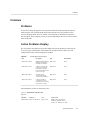
Problems .....................................................................................................
Problems .............................................................................................
Active Problems Display .......................................................................
Repairing problems ...............................................................................
Related features ...................................................................................
Logs ...........................................................................................................
Logs ...................................................................................................
BUI ...................................................................................................
CLI ....................................................................................................
Maintenance Workflows ................................................................................
Using Workflows .........................................................................................
Workflow Execution Context ..........................................................................
Workflow Parameters ....................................................................................
Constrained Parameters .........................................................................
Optional Parameters ..............................................................................
Workflow Error Handling ..............................................................................
Workflow Input Validation .............................................................................
Workflow Execution Auditing ........................................................................
Workflow Execution Reporting .......................................................................
Versioning ...................................................................................................
292
292
292
292
293
293
293
293
293
293
294
294
294
294
294
294
294
294
295
295
301
301
301
302
302
302
302
305
306
310
310
311
311
313
314
314
315
316
316
318
5
Contents
Appliance Versioning ............................................................................
Workflow Versioning ............................................................................
Workflows as Alert Actions ...........................................................................
Alert Action Execution Context ..............................................................
Auditing Alert Actions ..........................................................................
Using Scheduled Workflows ..........................................................................
Using the CLI ......................................................................................
Coding the Schedule .............................................................................
Example: Device Type Selection .....................................................................
BUI ...........................................................................................................
CLI ............................................................................................................
Downloading Workflows .......................................................................
Viewing Workflows ..............................................................................
Executing Workflows ............................................................................
6
Oracle ZFS Storage Appliance Customer Service Manual, Release 2013.1.3.0 • December 2014
318
319
319
319
320
321
321
322
324
327
327
327
328
329
Introduction
Overview
Controllers
■
■
■
■
■
■
■
■
“ZS4-4 Hardware Overview” on page 25 - component diagrams and specifications
“ZS4-4 Maintenance Procedures” on page 119 - replace controller drives, fans, power
supplies, memory, cards, risers, and batteries
“ZS3-4 Hardware Overview” on page 39 - component diagrams and specifications
“ZS3-4 Maintenance Procedures” on page 141 - replace controller drives, fans, power
supplies, memory, cards, risers, and batteries
“ZS3-2 Hardware Overview” on page 53 - component diagrams and specifications
“ZS3-2 Maintenance Procedures” on page 168 - replace controller drives, fans, power
supplies, memory, cards, and batteries
“7420 Hardware Overview” on page 69 | “7320 Hardware Overview” on page 83 |
“7120 Hardware Overview” on page 94- component diagrams and specifications
“7x20 Maintenance Procedures” on page 203 - replace controller drives, fans, power
supplies, memory, cards, risers, and batteries
Introduction
7
Overview
Expansion Storage
■
■
■
“Disk Shelf Overview” on page 105 - component diagrams and specifications for
Oracle Storage Drive Enclosure DE2-24, and Sun Disk Shelf
“Disk Shelf Maintenance Procedures” on page 242 - replace disk shelf chassis
components
“Connecting to Attached Storage” in “Oracle ZFS Storage Appliance Cabling Guide,
Release 2013.1.3.0 ” - cabling storage controllers to the disk shelves
Protocols
Oracle ZFS Storage Appliances include support for a variety of industry-standard client
protocols, including:
■
SMB
■
NFS
■
HTTP and HTTPS
■
WebDAV
■
■
■
■
■
■
iSCSI
FC
SRP
iSER
FTP
SFTP
For information on these protocols, see the “Oracle ZFS Storage Appliance Administration
Guide, Release 2013.1.3.0 ”.
Key Features
Oracle ZFS Storage Appliances also include new technologies to deliver the best storage price/
performance and unprecedented observability of your workloads in production, including:
■
Analytics, a system for dynamically observing the behavior of your system in real-time
and viewing data graphically. For more information, see “Analytics” in “Oracle ZFS
Storage Appliance Analytics Guide, Release 2013.1.3.0 ”.
■
8
The ZFS Hybrid Storage Pool, composed of optional Flash-memory devices for
acceleration of reads and writes, low-power, high-capacity disks, and DRAM memory, all
managed transparently as a single data hierarchy.
Oracle ZFS Storage Appliance Customer Service Manual, Release 2013.1.3.0 • December 2014
Overview
Data Services
To manage the data that you export using these protocols, you can configure your Oracle ZFS
Storage Appliance using the built-in collection of advanced data services, including:
LICENSE NOTICE: Remote Replication and Cloning may be evaluated free of charge, but each feature requires
that an independent license be purchased separately for use in production. After the evaluation period, these features
must either be licensed or deactivated. Oracle reserves the right to audit for licensing compliance at any time.
For details, refer to the "Oracle Software License Agreement ("SLA") and Entitlement for Hardware Systems with
Integrated Software Options."
■
■
■
■
■
■
■
■
■
RAID-Z (RAID-5 and RAID-6), mirrored, and striped disk configurations
Unlimited read-only and read-write snapshots, with snapshot schedules
Data deduplication
Built-in data compression
Remote replication of data for disaster recovery
Active-active clustering for high availability
Thin provisioning of iSCSI LUNs
Virus scanning and quarantine
NDMP backup and restore
For information on these data services, see the “Oracle ZFS Storage Appliance Administration
Guide, Release 2013.1.3.0 ”.
Availability
To maximize the availability of your data in production, Oracle ZFS Storage Appliances include
a complete end-to-end architecture for data integrity, including redundancies at every level of
the stack. Key features include:
■
Predictive self-healing and diagnosis of all system hardware failures: CPUs, DRAM, I/O
cards, disks, fans, power supplies
■
ZFS end-to-end data checksums of all data and metadata, protecting data throughout the
stack
■
RAID-6 (double- and triple-parity) and optional RAID-6 across disk shelves
■
Active-active clustering for high availability
■
Link aggregations and IP multipathing for network failure protection
■
I/O Multipathing between the controller and disk shelves
■
Integrated software restart of all system software services
■
Phone Home of telemetry for all software and hardware issues
Introduction
9
Overview
■
Lights-out Management of each system for remote power control and console access
For information on these availability features, see the “Oracle ZFS Storage Appliance
Administration Guide, Release 2013.1.3.0 ”.
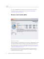
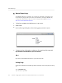
Browser User Interface (BUI)
The browser user interface
The BUI is the graphical tool for administration of the appliance. The BUI provides an intuitive
environment for administration tasks, visualizing concepts, and analyzing performance data.
The management software is designed to be fully featured and functional on a variety of web
browsers, as described in “Browser User Interface (BUI)” in “Oracle ZFS Storage Appliance
Administration Guide, Release 2013.1.3.0 ”.
Direct your browser to the system using either the IP address or host name you assigned
to the NET-0 port during initial configuration as follows: https://ipaddress:215 or https://
hostname:215. The login screen appears.
10
Oracle ZFS Storage Appliance Customer Service Manual, Release 2013.1.3.0 • December 2014
Hardware
The online help linked in the top right of the BUI is context-sensitive. For every top-level and
second-level screen in the BUI, the associated help page appears when you click the Help
button.
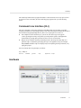
Command Line Interface (CLI)
The CLI is designed to mirror the capabilities of the BUI, while also providing a powerful
scripting environment for performing repetitive tasks. The following sections describe details of
the CLI. When navigating through the CLI, there are two principles to be aware of:
■
Tab completion is used extensively: if you are not sure what to type in any given
context, pressing the Tab key will provide you with possible options. Throughout the
documentation, pressing Tab is presented as the word "tab" in bold italics.
■
Help is always available: the help command provides context-specific help. Help on a
particular topic is available by specifying the topic as an argument to help, for example
help commands. Available topics are displayed by tab-completing the help command, or by
typing help topics.
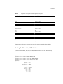
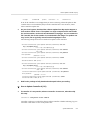
You can combine these two principles, as follows:
dory:> help tab
builtins
commands
general
help
properties script
Hardware
Introduction
11
Hardware
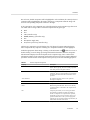
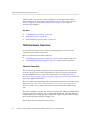
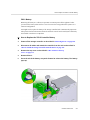
Locating a disk
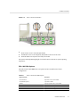
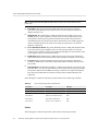
Hardware View
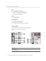
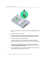
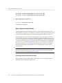
The Maintenance > Hardware screen (also known as the "hardware view") provides component
status of the appliance and attached disk shelves. This information is available from both the
BUI and the CLI.
BUI
The BUI hardware view provides interactive illustrations that enable you to browse through the
appliance and attached disk shelf components. The screenshot at the start of this section shows a
disk highlighted in a Sun ZFS Storage 7320, showing both its physical location and details.
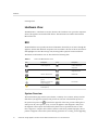
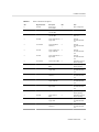
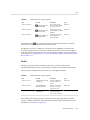
The buttons in the hardware view are described in the following table:
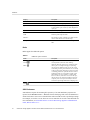
TABLE 1
Icon
Icons in the BUI Hardware View
Description
Icon
Description
Show a more detailed view
of this component
Toggle blinking of the
locator LED for this
component
Leave this detailed view
Power off, reboot, or
diagnostic reboot
Click for more details
Offline disk
Hardware component is ok
(green)
Port active
Hardware component is
not present (grey)
Port inactive
Hardware component is
faulted (amber)
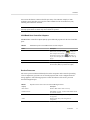
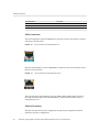
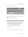
System Overview
The main hardware page lists the system chassis, a summary of its contents, and any attached
disk shelves (on supported systems). This provides an overview of the hardware present on
the system. The power icon
, located in the upper left of the view, presents a dialog box to
either power off, reboot (power cycle), or reboot the appliance with diagnostics. Only select
the diagnostic reboot option when instructed by Oracle Service personnel because it could
take a long time to complete and could have adverse results if not performed properly. Do not
perform a diagnostic reboot when system-affecting operations are occurring, such as upgrading
12
Oracle ZFS Storage Appliance Customer Service Manual, Release 2013.1.3.0 • December 2014
Hardware
firmware, executing commands, and configuring or unconfiguring storage. The diagnostic
reboot option is not available when using the system chassis power icon, described below.
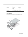
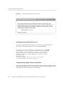
System Chassis
The primary system chassis is shown on the top half of the view. At the top left, click the rightarrow icon
to get more detail about the chassis. The indicator notes if there are any faulted
components within the chassis, and the name of the chassis. The chassis name is initially set to
the appliance name during installation. To change the chassis name, use the entry field on the
Configuration > Services > System Identity screen. For more information, see “Working with
System Identity” in “Oracle ZFS Storage Appliance Administration Guide, Release 2013.1.3.0
”.
At the top right of the system chassis is the locator icon
power icon
appliance.
to light the locator LED, and the
, which presents a dialog box to either power off or reboot (power cycle) the
A thumbnail of the controller is presented at left. Clicking on the thumbnail or the "Show
Details" link takes you to a detailed view of the chassis, and is identical to clicking on the rightarrow icon
at the top left of the view.
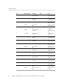
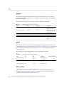
The following information is presented in a summary view:
TABLE 2
System Chassis Properties
Property
Description
Manufacturer
Manufacturer of the system
Model
System model name
Serial
System chassis hardware serial number
Processors
Count and description of processors in the system
Memory
Total memory in the system
System
Size and number of system disks used for the system
image
Data
Size and number of data disks in the system chassis. This
is only valid for standalone systems. If there are no data
disks present, "-" will be displayed.
Cache
Size and number of cache disks in the system chassis.
This is only valid for expandable systems that support
additional disk shelves. If there are no cache disks
present, "-" will be displayed.
Log
Size and number of log disks in the system chassis. This
is only valid for standalone systems. If there are no log
devices present, "-" will be displayed.
Total
Total size and count of all disks in the system.
Introduction
13
Hardware
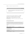
Disk Shelves
A list of disk shelves, if supported, is displayed at the bottom of the view. The thumbnail to the
left represents the front of the currently selected disk shelf. Clicking on the right-pointing arrow
or double-clicking on a row within the list will provide complete details about the disk shelf.
The state indicator will be orange if the chassis contains any faulted components. The following
fields are displayed in the list:
TABLE 3
Disk Shelf Properties
Property
Description
Name
Name of the disk shelf, used in faults and alerts. This is
initially set to the serial number of the disk shelf, but can
be changed by clicking on the name within the list.
MFR/MODEL
The disk shelf manufacturer and the model number.
RPM
Revolutions per minute; the speed of the disk drive.
Data
Total size of all data disks within the disk shelf.
Cache
Total size of all read-optimized cache devices
("Readzillas") within the drive shelf. There are currently
no supported disk shelves with read cache devices, but
this may not always be the case. If there are no cache
devices within the shelf, then "-" is displayed.
Log
Total size of all write-optimized cache devices
("Logzillas") within the drive shelf. If there are no log
devices within the shelf, then "-" is displayed.
Paths
Total number of I/O paths to the disk shelf. The only
supported configurations are those with multiple paths to
all disks, so this should read "2" under normal operating
circumstances. Clicking the information icon
will
bring up a dialog with information about each path. This
includes which HBAs are connected to the disk shelf,
and the state of any paths. If the disks within the disk
shelf are not currently configured as part of a storage
pool, complete path information will not be available,
though it displays two paths to the chassis.
Locate
Toggle the locator LED for this disk shelf. If the LED is
currently on, then this indicator will be flashing.
Chassis Detail
To view the chassis details, click on the right-arrow icon
(or one of the alternative forms
described above). This view includes some of the same controls in the upper left (state, name,
locate, reset, power off), as well as listings of all the components in the chassis.
At the left is a set of images describing the chassis. If there are multiple views, then you can
switch between them by clicking on the name of the view above the image.
14
Oracle ZFS Storage Appliance Customer Service Manual, Release 2013.1.3.0 • December 2014
Hardware
For each view, faulted components will be highlighted in red. In addition, the currently selected
component will be highlighted in the image. Clicking on a component within the image will
select the corresponding component in the list to the right.
A tab is present for each component type in the following list. Each component type has a state
icon which will be orange if there is a faulted component of the given type.
■
Disk
■
Slot
■
CPU (controller only)
■
DIMM (Memory) (controller only)
■
Fan
■
PSU (Power supply unit)
■
SP (Service processor) (controller only)
Clicking on a component type will display a list of all physical locations within the chassis
where components may be present. Clicking on a component within the list will highlight it
within the appropriate chassis image. Clicking on the information icon
while over a row or
double-clicking a row will bring up a dialog with detailed information about the component.
The information displayed in the list depends on the component type, but is a subset of the
information available in the component detail. Disks and service processors support additional
operations described below. Each component can report any or all of the following properties:
TABLE 4
Chassis Component Properties
Property
Description
Label
Human-readable identifier for this component within the
chassis. This is typically, but not necessarily, equivalent
to the label printed on the physical chassis.
FMRI
Fault managed resource identifier (FMRI) for the
component. This is an internal identifier used to identify
the component within faults and is intended for service
personnel.
Active Problems
For a faulted component, links to active problems
affecting the component.
Manufacturer
Component manufacturer.
Model
Component model.
Build
Manufacturing build identifier. This is used to identify
a particular location or batch where the component was
manufactured.
Part
Component part number, or core factory part number.
The orderable part number may differ, depending on
whether a component is for replacement or expansion,
and whether it's part of a larger assembly. Your service
provider should be able to refer you to the appropriate
orderable part. For components without part numbers, the
model number should be used instead.
Serial
Component serial number.
Introduction
15
Hardware
Property
Description
Revision
Firmware or hardware revision of the component.
Size
Total memory or storage, in bytes.
Type
Disk type. Can be one of 'system', 'data', 'log', 'cache',
or 'spare'. When a spare is active, it will be displayed as
'spare [A]'.
Speed
Processor speed, in gigahertz.
Cores
Number of CPU cores.
GUID
Hardware global unique identifier.
Endurance
The lifetime percentage remaining on an SSD. Lifetime
starts at 100% and decreases with disk usage.
Last Update
The date and time of the last endurance reading of the
SSD.
Disks
Disks support the additional options:
TABLE 5
Additional Options for Disks
Action
Description
Locate
Toggle the locator indicator for the disk. If the LED is
currently turned on, this icon will be blinking.
Offline
Online
Offline the disk. This option is only available for disks
that are part of a configured storage pool (including
the system pool). Offlining a disk prevents the system
from reading or writing to it. Faulted devices are already
avoided, so this option should only be required if a disk
is exhibiting performance problems that do not result in
pathological failure. It is not possible to offline a disk
that would prevent access to data (i.e. offlining both
halves of a mirror). If the device is an active hot spare,
this will also give the option of detaching the hot spare
completely. Once a hot spare is detached, it cannot be
activated except through another fault or hotplug event.
Online the disk. Reverses the above operation.
SSD Endurance
SSD endurance reports the remaining life expectancy of an SSD. Endurance properties are
reported on the BUI Maintenance > Hardware chassis details page and in the CLI maintenance
chassis disk context. You can set a threshold alert when an SSD exceeds a specified percentage.
For example, set an alert to occur when one or more SSD devices exceeds a 95% threshold. For
more information, see “Threshold Alerts” in “Oracle ZFS Storage Appliance Administration
Guide, Release 2013.1.3.0 ”.
16
Oracle ZFS Storage Appliance Customer Service Manual, Release 2013.1.3.0 • December 2014
Hardware
You can use this feature to monitor the life expectancy of an SSD. For example, if SSD
endurance reports 50% after two years, the SSD is estimated to last for another two years,
assuming the workload is consistent.
Note - Do not use reported SSD endurance percentage as an indication to replace the SSD. SSD
warranty replacements are made only when a failure is reported.
InfiniBand Host Controller Adapters
InfiniBand Host Controller Adapters (HCA) report additional properties for the list of available
ports:
TABLE 6
Additional Properties for InfiniBand Host Controller Adapters
Action
Description
State
When "active", the active-port icon
is displayed.
Other valid port states ("down", "init", and "arm") are
denoted by the inactive-port icon
. Mousing over
the port icon will display the current port state in the tip
pop-up.
GUID
The hardware assigned port GUID.
Speed
The current port speed enabled: Single Data Rate (SDR),
Dual Data Rate (DDR) or Quad Data Rate (QDR)
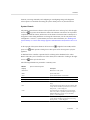
Service Processor
The service processor behaves differently from other component nodes. Instead of providing
a list of components, it presents a set of network properties that can be configured from the
storage appliance. The following properties control the behavior of the service processor
network management port.
TABLE 7
Properties for the Service Processor Network Management Port
Property
Description
MAC Address
Hardware MAC address. This is read-only
IP Address Source
Either 'DHCP' or 'Static'. Controls whether DHCP should
be used on the interface.
IP Address
IPv4 Address, when using static IP configuration. IPv6 is
not supported.
Subnet
Dotted decimal subnet, when using static IP
configuration.
Default Gateway
IPv4 default gateway address.
Introduction
17
Hardware
Changing multiple values in conflicting ways (such as changing static IP assignments while in
DHCP mode) has undefined behavior.
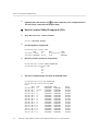
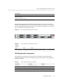
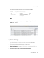
CLI
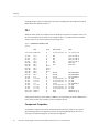
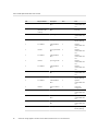
Hardware status details are available in the CLI under the maintenance hardware section. Use
the show command to list the status of all components. The list command will list available
chassis, which can be selected and then viewed using show.
tarpon:> maintenance hardware show
Chassis:
NAME
STATE
MANUFACTURER
chassis-000 0839QCJ01A
ok
Sun Microsystems, Inc. Sun Storage 7320
cpu-000
cpu-001
cpu-002
cpu-003
disk-000
disk-001
disk-002
disk-003
disk-004
disk-005
disk-006
disk-007
fan-000
fan-001
fan-002
fan-003
fan-004
fan-005
fan-006
fan-007
memory-000
memory-001
...
ok
ok
ok
ok
ok
ok
absent
absent
absent
absent
ok
ok
ok
ok
ok
ok
ok
ok
ok
ok
ok
ok
AMD
AMD
AMD
AMD
STEC
STEC
HITACHI
HITACHI
unknown
Sun Microsystems,
Sun Microsystems,
Sun Microsystems,
unknown
Sun Microsystems,
Sun Microsystems,
Sun Microsystems,
HYNIX
HYNIX
CPU 0
CPU 1
CPU 2
CPU 3
HDD 0
HDD 1
HDD 2
HDD 3
HDD 4
HDD 5
HDD 6
HDD 7
FT 0
FT 0 FM 0
FT 0 FM 1
FT 0 FM 2
FT 1
FT 1 FM 0
FT 1 FM 1
FT 1 FM 2
DIMM 0/0
DIMM 0/1
MODEL
Inc.
Inc.
Inc.
Inc.
Inc.
Inc.
Quad-Core AMD Op
Quad-Core AMD Op
Quad-Core AMD Op
Quad-Core AMD Op
MACH8 IOPS
MACH8 IOPS
HTE5450SASUN500G
HTE5450SASUN500G
ASY,FAN,BOARD,H2
541-2068
541-2068
541-2068
ASY,FAN,BOARD,H2
541-2068
541-2068
541-2068
4096MB DDR-II 66
4096MB DDR-II 66
A 5th and 6th column for serial number ("SERIAL") and revolutions per minute ("RPM") have
been truncated in the above example, as has the length of this list.
Component Properties
If a particular component is selected, detailed information about its properties are reported.
The following properties are supported, with the corresponding BUI property name. For a
description of a particular property, see the earlier descriptions.
18
Oracle ZFS Storage Appliance Customer Service Manual, Release 2013.1.3.0 • December 2014
Hardware
TABLE 8
Component CLI Properties and BUI Equivalent Properties
CLI Property
BUI Property
build
Build
cores
Cores
device
N/A
faulted
(status indicator)
label
Label
locate (writable)
(status indicator)
manufacturer
Manufacturer
model
Model
offline (writeable)
(status indicator)
part
Part
present
(status indicator)
revision
Revision
serial
Serial
size
Size
speed
Speed
type
(combined with use)
use
Type
When viewing a disk that is active as a hot spare, the detach command is also available.
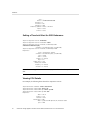
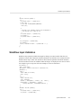
Viewing the Remaining SSD Lifetime
As shown in this example, disk-015 is at 100% which indicates a new SSD. The remaining
lifetime estimate decreases as the disk is used.
tarpon maintenance
tarpon:maintenance
tarpon:maintenance
tarpon:maintenance
tarpon:maintenance
Properties:
hardware
hardware> select chassis-001
hardware chassis-001> select disk
hardware chassis-001> select disk-015
hardware chassis-001 disk-015> list
label
present
faulted
manufacturer
model
serial
revision
size
type
use
=
=
=
=
=
=
=
=
=
=
HDD 15
true
false
SANDISK
LB806M---SUN800G
40042896
S30E
745G
data
data
Introduction
19
Hardware
rpm
device
pathcount
interface
endurance
endurance_updated
locate
offline
=
=
=
=
=
=
=
=
-c0t5001E82002630190d0
2
SAS
100%
2014-3-3 22:04:14
false
false
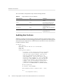
Setting a Threshold Alert for SSD Endurance
tarpon:configuration alerts> thresholds
tarpon:configuration alerts thresholds> create
tarpon:configuration alerts threshold (uncommitted)> set
statname=ssd.endurance[ssd]
statname = ssd.endurance[ssd] (uncommitted)
tarpon:configuration alerts threshold (uncommitted)> list
Properties:
uuid = <generated on commit>
statname = ssd.endurance[ssd] (uncommitted)
type = normal
limit = (unset)
minpost = 5 minutes
days = all
window_start = none
window_end = 00:00
frequency = 5 minutes
minclear = 5 minutes
Note - The remaining fields are set the same way you would set them for any other threshold
alert.
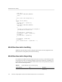
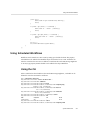
Viewing CPU Details
For example, the following shows details for component "CPU 0":
hardware> select chassis-000
chassis-000> select cpu
chassis-000 cpu> select cpu-000
chassis-000 cpu-000> show
tarpon:maintenance
tarpon:maintenance
tarpon:maintenance
tarpon:maintenance
Properties:
label
present
faulted
manufacturer
model
part
20
=
=
=
=
=
=
CPU 0
true
false
AMD
Quad-Core AMD Opteron(tm) Processor 8356
1002
Oracle ZFS Storage Appliance Customer Service Manual, Release 2013.1.3.0 • December 2014
How to Locate a Failed Component (BUI)
revision = 03
cores = 4
speed = 2.14G
Restarting the Appliance
Only issue the restart command as instructed by Oracle Service personnel. This function is only
available via the CLI and is not the same as a reboot (power cycle) via the BUI. The restart
command is a software-only operation that restarts the management server, which could impact
some client services, like replication. During execution, both the CLI and BUI are not available;
wait for the appliance to return to normal operation.
Under the maintenance system context, issue the command restart.
tarpon:maintenance system> restart
Performing a Diagnostic Reboot
Only issue the diagnostic reboot command as instructed by Oracle Service personnel. A
diagnostic reboot gathers diagnostic information before power cycling the appliance. This
operation could take a long time to complete and could cause adverse results if not performed
properly. Do not reboot when system-affecting operations are occurring, such as upgrading
firmware, executing commands, and configuring or unconfiguring storage.
Under the maintenance system context, issue the command diagreboot.
tarpon:maintenance system> diagreboot
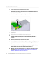
Tasks
How to Locate a Failed Component (BUI)
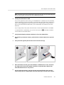
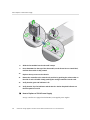
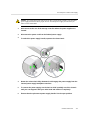
1.
2.
3.
Go to the Maintenance > Hardware screen.
Click the right-arrow icon
fault icon.
on the Storage System or Disk Shelf which has the
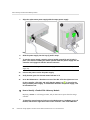
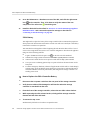
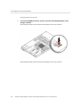
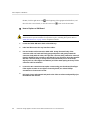
Locate the fault icon in the lists of hardware components, and click it. The image
should be updated to show where that component is physically located.
Introduction
21
How to Locate a Failed Component (CLI)
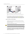
4.
(Optional) Click the locator icon
for that component, if the component has it.
The LED on the component will begin to flash.
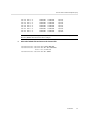
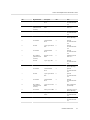
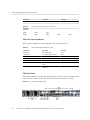
How to Locate a Failed Component (CLI)
1.
Go to the maintenance hardware context:
hostname:> maintenance hardware
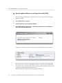
2.
List the appliance components:
hostname:maintenance hardware> list
NAME
STATE
MODEL
SERIAL
chassis-000 hostname
ok
Sun Storage 7320 unknown
chassis-001 000000000C faulted
J4410
000000000C
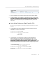
3.
Select the chassis and list its components:
hostname:maintenance hardware> select chassis-001
hostname:maintenance chassis-001> list
disk
fan
psu
slot
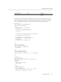
4.
Select the component type and show all available disks:
hostname:maintenance chassis-001> select disk
hostname:maintenance chassis-001 disk> show
Disks:
LABEL STATE
MANUFACTURER MODEL
disk-000 HDD 0 ok
ST3500630NS ST3500630NS
disk-001 HDD 1 faulted
ST3500630NS ST3500630NS
disk-002 HDD 2 ok
ST3500630NS ST3500630NS
disk-003 HDD 3 ok
ST3500630NS ST3500630NS
disk-004 HDD 4 ok
ST3500630NS ST3500630NS
disk-005 HDD 5 ok
ST3500630NS ST3500630NS
disk-006 HDD 6 ok
ST3500630NS ST3500630NS
disk-007 HDD 7 ok
ST3500630NS ST3500630NS
disk-008 HDD 8 ok
ST3500630NS ST3500630NS
disk-009 HDD 9 ok
ST3500630NS ST3500630NS
disk-010 HDD 10 ok
ST3500630NS ST3500630NS
disk-011 HDD 11 ok
ST3500630NS ST3500630NS
disk-012 HDD 12 ok
ST3500630NS ST3500630NS
disk-013 HDD 13 ok
ST3500630NS ST3500630NS
disk-014 HDD 14 ok
ST3500630NS ST3500630NS
22
SERIAL
9QG1ACNJ
9QG1A77R
9QG1AC3Z
9QG1ACKW
9QG1ACKF
9QG1ACPM
9QG1ACRR
9QG1ACGD
9QG1ACG4
9QG1ABDZ
9QG1A769
9QG1AC27
9QG1AC41
9QG1ACQ5
9QG1ACKA
Oracle ZFS Storage Appliance Customer Service Manual, Release 2013.1.3.0 • December 2014
How to Locate a Failed Component (CLI)
disk-015
disk-016
disk-017
disk-018
disk-019
disk-020
disk-021
disk-022
disk-023
HDD
HDD
HDD
HDD
HDD
HDD
HDD
HDD
HDD
15
16
17
18
19
20
21
22
23
ok
ok
ok
ok
ok
ok
ok
ok
ok
ST3500630NS
ST3500630NS
ST3500630NS
ST3500630NS
ST3500630NS
ST3500630NS
ST3500630NS
ST3500630NS
ST3500630NS
ST3500630NS
ST3500630NS
ST3500630NS
ST3500630NS
ST3500630NS
ST3500630NS
ST3500630NS
ST3500630NS
ST3500630NS
9QG1AC5Y
9QG1ACQ2
9QG1A76S
9QG1ACDY
9QG1AC3Y
9QG1ACG6
9QG1AC3X
9QG1ACHL
9QG1ABLW
Note - The RPM (revolutions per minute) of the disk drive is also shown in the output.
However, RPM is truncated in the above example.
5.
Select the faulted disk and turn on the locator LED:
hostname:maintenance chassis-001 disk> select disk-001
hostname:maintenance chassis-001 disk-001> set locate=true
locate = true (uncommitted)
hostname:maintenance chassis-001 disk-001> commit
Introduction
23
24
Oracle ZFS Storage Appliance Customer Service Manual, Release 2013.1.3.0 • December 2014
Hardware Maintenance
To maintain the system hardware, use the following sections:
■
“Hardware Overviews” on page 25
■
“Maintenance Procedures” on page 118
■
“Hardware Faults” on page 257
■
“Cabling” on page 259
Hardware Overviews
This section contains hardware overviews for the following appliance components:
■
“ZS4-4 Hardware Overview” on page 25
■
“ZS3-4 Hardware Overview” on page 39
■
“ZS3-2 Hardware Overview” on page 53
■
“7420 Hardware Overview” on page 69
■
“7320 Hardware Overview” on page 83
■
“7120 Hardware Overview” on page 94
■
“Disk Shelf Overview” on page 105
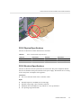
ZS4-4 Hardware Overview
Use the information on this page as a preparation reference for servicing replaceable
components of the Oracle ZFS Storage ZS4-4 controller. Refer to the following topics for
procedural instructions:
■
“ZS4-4 Maintenance Procedures” on page 119 - replace system controller components
■
“Disk Shelf Maintenance Procedures” on page 242 - replace disk shelf components
ZS4-4 Controller Overview
The ZS4-4 controller can be configured as a single controller or two controllers to create a highavailability cluster configuration. The following table describes the base configuration.
Hardware Maintenance
25
Hardware Overviews
TABLE 9
ZS4-4 Controller Base Configuration
Component
Description
CPU
Four Intel Xeon 15-core, 2.8 GHz
Memory
1.5TB 16GB DDR3 LV RDIMM
Boot Disks
Two 2.5-inch 900GB SAS-2 HDDs
Read Flash
Up to four optional 2.5-inch 1.6TB SAS-2 SSDs
HBAs
Two 4x4-port SAS-2 (base configuration)
PCIe slots
11 (4 base configuration, 7 expansion slots)
Refer to the Oracle ZFS Storage ZS4-4 data sheet at http://www.oracle.com/goto/zs4-4
for the most recent component specification and physical, electrical, and environmental
specifications.
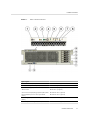
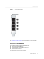
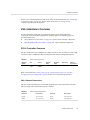
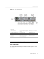
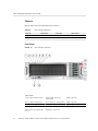
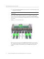
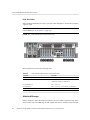
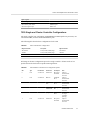
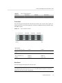
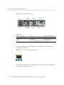
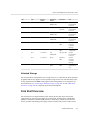
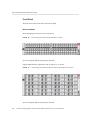
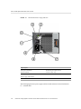
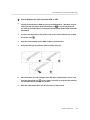
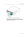
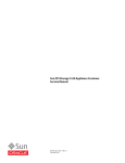
ZS4-4 Front Panel
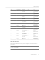
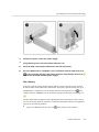
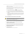
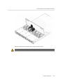
The ZS4-4 controller drive slots and front panel components are shown in the following figure.
26
Oracle ZFS Storage Appliance Customer Service Manual, Release 2013.1.3.0 • December 2014
Hardware Overviews
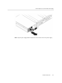
FIGURE 1
ZS4-4 Controller Front Panel
Figure Legend
1 Locator LED/button (white)
9 USB 2.0 connectors (2)
2 Service action required LED (amber)
10 DB-15 video port
3 Power/OK LED (green)
11 Boot drive 0 (required)
4 Power button
12 Boot drive 1 (required)
5 Service Processor (SP) OK (green)/Fault (amber) LED
13 Solid state drive 2 (optional)
6 Fan/CPU/Memory Service action required LED
(amber)
14 Solid state drive 3 (optional)
7 Power Supply (PS) Service action required LED
(amber)
15 Solid state drive 4 (optional)
8 Over temperature warning LED (amber)
16 Solid state drive 5 (optional)
Hardware Maintenance
27
Hardware Overviews
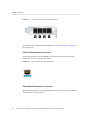
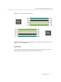
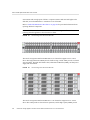
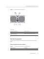
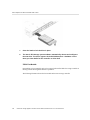
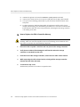
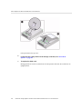
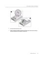
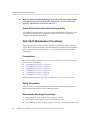
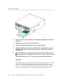
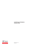
The ZS4-4 controller has two 2.5-inch 900GB SAS-2 system boot drives in slots 0 and 1,
configured as a mirrored pair. Up to four 1.6TB SAS-2 Read flash SSDs can fill slots 2 through
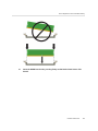
5, in that order. A filler panel must be installed in empty drive slots. The system drive LEDs are
shown in the following figure.
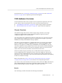
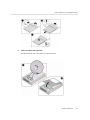
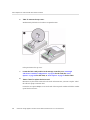
FIGURE 2
System Drive LEDs
TABLE 10
System Drive LEDs
Figure Legend
1 Locate (white)
2 Service action required (amber)
3 OK/Activity (green)
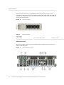
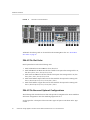
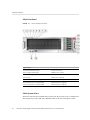
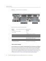
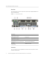
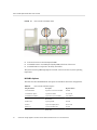
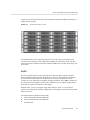
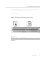
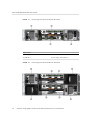
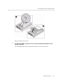
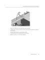
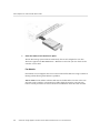
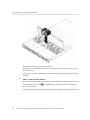
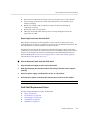
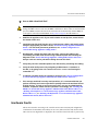
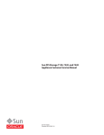
ZS4-4 Rear Panel
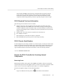
The ZS4-4 rear panel is shown in the following figure. Base configuration PCIe cards are not
depicted in this illustration.
FIGURE 3
28
ZS4-4 Controller Rear Panel
Oracle ZFS Storage Appliance Customer Service Manual, Release 2013.1.3.0 • December 2014
Hardware Overviews
Figure Legend
1 Power supply unit (PSU) 0 indicator panel
7 Network (NET) 10 GbE ports: NET0NET3
2 PSU 0 AC inlet
8 USB 2.0 connectors (2)
3 PSU 1 indicator panel
9 PCIe card slots 711
4 PSU 1 AC inlet
10 Service processor (SP) network management (NET MGT) port
5 System status indicator panel
11 Serial management (SER MGT) RJ-45 port
6 PCIe card slots 1-6
12 DB-15 video port
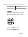
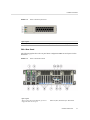
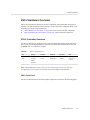
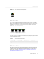
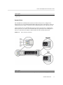
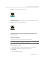
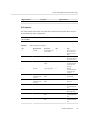
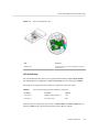
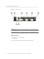
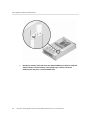
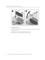
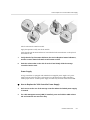
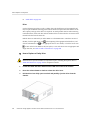
ZS4-4 Ethernet Ports
The ZS4-4 has four RJ-45 10-Gigabit Ethernet (10GbE) network connectors on the rear panel,
labeled NET 0, NET 1, NET 2, and NET 3 (bottom left to top right), as shown in the following
figure. Use these ports to connect the appliance to the network.
The LEDs located above the NET ports, labeled 2, 0, 3, 1 (left to right) are Link/Activity
indicators.
FIGURE 4
Ethernet Ports
LED
Status
OFF (1)
No Link
ON (0)
Link and no activity
Blink
Link and activity
Note - Speed is not indicated for the NET ports.
Hardware Maintenance
29
Hardware Overviews
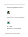
ZS4-4 Network Management Port
The network management connector (NET MGT), shown in the following figure, is an RJ-45
port and provides an alternate terminal interface to the service processor (SP) console.
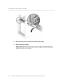
FIGURE 5
Network Management Port
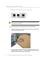
ZS4-4 Serial Management Port
The serial management connector (SER MGT), shown in the following figure, is an RJ-45 port
and provides a terminal connection to the SP console.
FIGURE 6
Serial Management Port
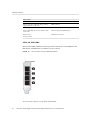
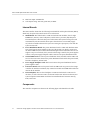
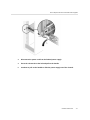
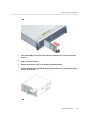
ZS4-4 4x4 SAS-2 HBA
The 4x4 SAS-2 HBA provides connectivity to external DE2-24 and Sun Disk Shelves. The
HBA ports are numbered 3-0, top to bottom, as shown in the following figure.
30
Oracle ZFS Storage Appliance Customer Service Manual, Release 2013.1.3.0 • December 2014
Hardware Overviews
FIGURE 7
4x4 SAS-2 HBA Port Numbers
See “ZS4-4 PCIe Slot Order” on page 32 for 4x4 SAS-2 HBA slot placement of the HBAs.
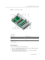
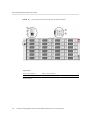
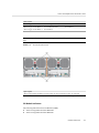
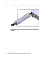
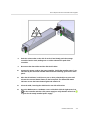
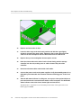
ZS4-4 PCIe I/O Slot Numbering
The ZS4-4 base configuration contains the following PCIe cards:
■
One 8-port SAS-2 internal HBA (slot 2)
■
Two 4-port (4x4) SAS-2 external HBAs (slot 6 and slot 7)
■
One cluster interface card (slot 4)
The following figure shows the PCIe I/O slot numbers.
Hardware Maintenance
31
Hardware Overviews
FIGURE 8
ZS4-4 PCIe I/O Slot Numbers
Additional client-facing cards can be installed in the remaining PCIe slots. See “ZS4-4 PCIe
Slot Order” on page 32.
ZS4-4 PCIe Slot Order
Install optional PCIe cards in the following order:
1. Install additional 4x4 SAS-2 HBAs in slot 9, then slot 3.
2. Install InfiniBand CX3 HCAs into the first available client-option slot starting with slot 11,
then slot 8, slot 5, slot 1, slot 10, slot 3, slot 9.
3. Install 16Gb FC HBAs into the first available client-option slot starting with slot 11, then
slot 8, slot 5, slot 1, slot 10, slot 3, slot 9.
4. Install 10Gb Ethernet Optical NICs into the first available client-option slot starting with
slot 11, then slot 8, slot 5, slot 1, slot 10, slot 3, slot 9.
5. Install 10Gb Ethernet Copper NICs into the first available client-option slot starting with
slot 11, then slot 8, slot 5, slot 1, slot 10, slot 3, slot 9.
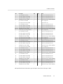
ZS4-4 PCIe Base and Optional Configurations
The following table describes the PCIe base and optional slot assignments for ZS4-4 standalone
and cluster configurations. PCIe slot numbering begins with slot 1.
See the legend for a description of the interconnect types and option codes shown in the Type
column.
32
Oracle ZFS Storage Appliance Customer Service Manual, Release 2013.1.3.0 • December 2014
Hardware Overviews
Slot
Description
Max
Type
Note
1
2-port InfiniBand CX3 HCA
4
A
Optional recommended front-end
1
2-port 10Gb Ethernet Optical NIC
4
C
Optional recommended front-end
1
2-port 10Gb Ethernet Copper NIC
4
D
Optional recommended front-end
1
16GB Dual Universal FC HBA
4
B
Optional FC target or initiator (Backup)
2
8-port SAS-2 Internal HBA
1
F
Base configuration
3
4-port (4x4) SAS-2 External HBA
4
E
Optional back-end
3
2-port InfiniBand CX3 HCA
4
A
Optional recommended front-end
3
2-port 10Gb Ethernet Optical NIC
4
C
Optional recommended front-end
3
2-port 10Gb Ethernet Copper NIC
4
D
Optional recommended front-end
3
16GB Dual Universal FC HBA
4
B
Optional FC target or initiator (Backup)
4
Cluster Interface (second generation)
1
G
Base configuration
5
2-port InfiniBand CX3 HCA
4
A
Optional recommended front-end
5
2-port 10Gb Ethernet Optical NIC
4
C
Optional recommended front-end
5
2-port 10Gb Ethernet Copper NIC
4
D
Optional recommended front-end
5
16GB Dual Universal FC HBA
4
B
Optional FC target or initiator (Backup)
6
4-port (4x4) SAS-2 External HBA
4
E
Base configuration
7
4-port (4x4) SAS-2 External HBA
4
E
Base configuration
8
2-port InfiniBand CX3 HCA
4
A
Optional recommended front-end
8
2-port 10Gb Ethernet Optical NIC
4
C
Optional recommended front-end
8
2-port 10Gb Ethernet Copper NIC
4
D
Optional recommended front-end
8
16GB Dual Universal FC HBA
4
B
Optional FC target or initiator (Backup)
9
4-port (4x4) SAS-2 External HBA
4
E
Base configuration
9
2-port InfiniBand CX3 HCA
4
A
Optional recommended front-end
9
2-port 10Gb Ethernet Optical NIC
4
C
Optional recommended front-end
9
2-port 10Gb Ethernet Copper NIC
4
D
Optional recommended front-end
9
16GB Dual Universal FC HBA
4
B
Optional FC target or initiator (Backup)
10
2-port InfiniBand CX3 HCA
4
A
Optional recommended front-end
10
2-port 10Gb Ethernet Optical NIC
4
C
Optional recommended front-end
10
2-port 10Gb Ethernet Copper NIC
4
D
Optional recommended front-end
10
16GB Dual Universal FC HBA
4
B
Optional FC target or initiator (Backup)
11
2-port InfiniBand CX3 HCA
4
A
Optional recommended front-end
11
2-port 10Gb Ethernet Optical NIC
4
C
Optional recommended front-end
11
2-port 10Gb Ethernet Copper NIC
4
D
Optional recommended front-end
11
16GB Dual Universal FC HBA
4
B
Optional FC target or initiator (Backup)
The legend describes the interconnect types and option codes shown in the Type column.
Hardware Maintenance
33
Hardware Overviews
Legend for Interconnect Types and Options
A
E
Storage Array 4-port External SAS-2 MiniSAS HD
InfiniBand QDR QSFP+
- QSFP Direct Copper Cable Connect
- SFF-8644 Mini-SAS HD to Mini-SAS
Copper
- Optical Transceiver QSFP Short Range 40Gbs
B
Fibre Channel 16Gb SFP+
F
- Optical Transceiver SFP Short Range 16Gbs
C
GbE NIC Multi-mode Fiber SFP+ 10GBase-SR/LR
- SFF-8087 Mini-SAS to Mini-SAS Copper
G
- Optical Transceiver SFP Short Range 10Gbs
GbE NIC UTP 10GBase-T
Server Heartbeat 2-port RS-232 1-port
1GBase-T
-Copper RJ-45 Serial RS-232
- Optical Transceiver SFP Long Range 10Gbs
D
HDD 8-port Internal SAS-2 Mini-SAS
-Copper RJ-45 Unshielded Twisted Pair
- Copper RJ-45 Unshielded Twisted Pair
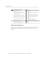
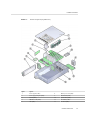
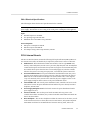
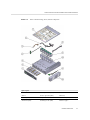
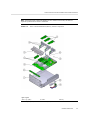
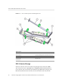
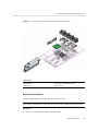
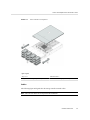
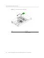
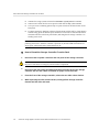
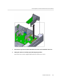
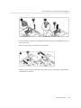
ZS4-4 Internal Components
The ZS4-4 chassis contains both customer-replaceable units (CRUs) and field-replaceable units
(FRUs) as shown in the following figure. FRUs must be replaced by trained Oracle service
technicians.
34
Oracle ZFS Storage Appliance Customer Service Manual, Release 2013.1.3.0 • December 2014
Hardware Overviews
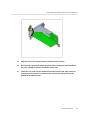
FIGURE 9
Internal Components (Exploded View)
Figure
Legend
1
Power supplies (CRU)
8
Memory riser card (CRU)
2
Power supply backplane (FRU)
9
Motherboard (FRU)
3
SP card (FRU)
10
System drive (CRU)
4
HBA/PCIe cards (CRU)
11
Fan module (CRU)
5
CPU (FRU)
12
Fan board (FRU)
Hardware Maintenance
35
Hardware Overviews
Figure
Legend
6
Heatsink (FRU)
13
Drive backplane (FRU)
7
Cover
14
Chassis
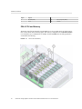
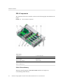
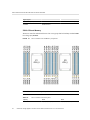
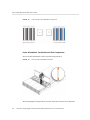
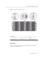
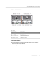
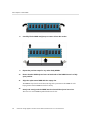
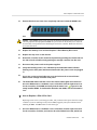
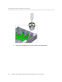
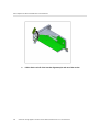
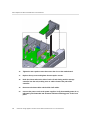
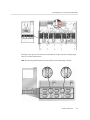
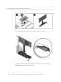
ZS4-4 CPU and Memory
The ZS4-4 controller has four Intel Xeon E7-8895 v2 15-core 2.8 GHz CPUs and eight memory
riser cards as shown in the following figure. The memory configuration is 16GB DDR3 DIMMs
to accommodate up to 1.5TB (ninety-six 16GB). All ZS4-4 DIMM risers are fully populated to
accommodate this offering.
FIGURE 10
36
ZS4-4 CPU and Memory
Oracle ZFS Storage Appliance Customer Service Manual, Release 2013.1.3.0 • December 2014
Hardware Overviews
Figure
Legend
1
Memory riser card P3/MR1
7
Memory riser card P0/MR1
2
Memory riser card P3/MR0
8
Memory riser card P0/MR0
3
Memory riser card P2/MR1
9
CPU P3
4
Memory riser card P2/MR0
10
CPU P2
5
Memory riser card P1/MR1
11
CPU P1
6
Memory riser card P1/MR0
12
CPU P0
Each memory riser card contains twelve DIMM slots, four DDR3 channels, and two memory
buffer ASICs. Each each memory buffer has two channels (A and B) and links to three
DIMM slots per channel. Each memory buffer is connected to the processor's built-in memory
controller by an SMI-2 link.
DIMM names in appliance logs and the Maintenance > Hardware view are displayed with the
full name, such as /SYS/MB/P0/D7.
For more information about memory layout and procedures for replacing DIMMs, see “ZS4-4
Maintenance Procedures” on page 119.
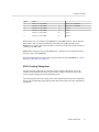
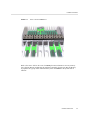
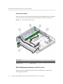
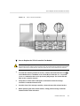
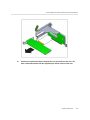
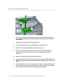
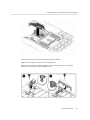
ZS4-4 Cooling Subsystem
The ZS4-4 internal components are cooled by air that is pulled in through the front of the
controller and exhausted out the back of the controller. Cooling occurs in two areas of the
chassis: the power supply area and the motherboard area.
The following figure shows the cooling zones and the approximate location of the temperature
sensors. The accompanying legend table provides sensor NAC names and sensor motherboard
designations.
Hardware Maintenance
37
Hardware Overviews
FIGURE 11
ZS4-4 Cooling Subsysem
Figure
Legend
0
Cooling zone 0
6
Temperature sensor TS_ZONE2 (U4505)
1
Cooling zone 1
7
Temperature sensor TS_OUT (U4506)
2
Cooling zone 2
8
Temperature sensor TS_TVL_1 (U4002)
3
Cooling zone 3 (power supply backplane area)
9
Temperature sensor TS_TVL_0 (U4302)
4
Temperature sensor TS_PS (U4603)
10
Temperature sensor TS_ZONE0_B (U4509)
5
Temperature sensor TS_ZONE1 (U4507)
11
Temperature sensor TS_ZONE0_A (U4508)
ZS4-4 Attached Storage
The ZS4-4 single and cluster controller configurations allow up to 36 disk shelves, consisting of
up to six chains of one to six disk shelves. Any combination of disk-only and Write flash disk
38
Oracle ZFS Storage Appliance Customer Service Manual, Release 2013.1.3.0 • December 2014
Hardware Overviews
shelves can be combined within the chain in any order. For more information, see “Connecting
to Attached Storage” on page 259. See also “Disk Shelf Overview” on page 105 for
component specifications and diagrams.
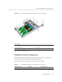
ZS3-4 Hardware Overview
Use the information on this page as a preparation reference for servicing replaceable
components of the Oracle ZFS Storage ZS3-4 controller. Refer to the following topics for
procedural instructions:
■
“ZS3-4 Maintenance Procedures” on page 141 - replace system controller components
■
“Disk Shelf Maintenance Procedures” on page 242 - replace disk shelf components
ZS3-4 Controller Overview
The ZS3-4 controller can be configured as a single controller or two controllers to create a highavailability cluster configuration. The following table describes the configuration options:
TABLE 11
Mktg Part
Number
7105725
ZS3-4 Controller Features
CPU
Memory
4x10-core, 2.
40GHz
1TB (16GB
DIMMs)
Readzilla
SAS-2
Boot Drive
SAS-2
HBA SAS-2
Software
Version (min)
Four 1.6TB
Two 900GB
4X4-port
2013.1.0
Refer to the product site at http://www.oracle.com/us/products/servers-storage/
storage/unified-storage/index.html for the most recent component specification.
ZS3-4 Chassis Dimensions
The ZS3-4 controller chassis fits in a standard equipment rack, and occupies three rack units
(3RU) in height. The chassis dimensions are as follows:
TABLE 12
ZS3-4 Controller Dimensions
Dimension
Measurement
Dimension
Measurement
Height
13.3 cm/5.25 in
Depth
70.6 cm/27.8 in
Width
43.7 cm/17.19 in
Weight
16.36 kg/96 lbs
Hardware Maintenance
39
Hardware Overviews
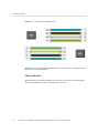
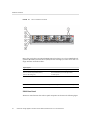
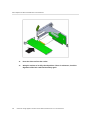
ZS3-4 Front Panel
FIGURE 12
ZS3-4 Controller Front Panel
Figure Legend
1 Locator LED and button (white)
9 USB 2.0 Connectors
2 Service Required LED (amber)
10 DB-15 video connector
3 Power/OK LED (green)
11 Boot drive 0
4 Power button
12 Boot drive 1 (required)
5 Service Processor (SP) OK LED (green)
13 Solid state drive 2 (optional)
6 Fan/CPU/Memory Service Required LED
14 Solid state drive 3 (optional)
7 Power Supply (PS) Service Required LED
15 Solid state drive 4 (optional)
8 Over Temperature Warning LED
16 Solid state drive 5 (optional)
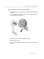
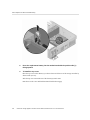
ZS3-4 System Drives
The ZS3-4 controller has two 900GB SAS-2 system boot drives in slots 0 and 1, configured as a
mirrored pair. Up to four 1.6TB SAS-2 Readzilla SSDs can fill slots 2 through 5, in order.
40
Oracle ZFS Storage Appliance Customer Service Manual, Release 2013.1.3.0 • December 2014
Hardware Overviews
FIGURE 13
ZS3-4 Controller System Drive
Figure Legend
1 Locate (white)
2 Service action required (amber)
3 OK/Activity (green)
ZS3-4 Rear Panel
The following graphic shows the rear panel. Base configuration HBAs are not depicted in this
illustration.
FIGURE 14
ZS3-4 Controller Rear Panel
Figure Legend
1 Power supply unit 0 status LEDs OK: green Power
Supply Fail: amber AC OK: green
8 Network (NET) 10/100/1000 ports: NET0-NET3
Hardware Maintenance
41
Hardware Overviews
Figure Legend
2 Power supply unit 0 AC inlet
9 USB 2.0 ports
3 Power supply unit 1 status LEDs OK: green Power
10 PCIe slots 5-9
4 Power supply unit 1 AC inlet
11 Network management (NET MGT) port
5 System status LEDs Power: green Attention: amber
12 Serial management (SER MGT) port
6 PCIe slots 0-4
13 DB-15 video connector
Supply Fail: amber AC OK: green
Locate: white
7 Cluster card slot
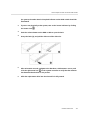
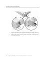
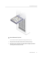
ZS3-4 4x4 SAS-2 HBA
The 4x4 SAS-2 HBA, installed in the ZS3-4, provides connectivity to external DE2 and Sun
Disk Shelves. The HBA ports are numbered 3-0, top to bottom:
FIGURE 15
ZS3-4 Controller 4x4 SAS-2 HBA Port Numbers
See “ZS3-4 PCIe Options” on page 48 for slot placement.
42
Oracle ZFS Storage Appliance Customer Service Manual, Release 2013.1.3.0 • December 2014
Hardware Overviews
ZS3-4 Electrical Specifications
The following list shows the electrical specifications for the controller.
Note - The power dissipation numbers listed are the maximum rated power numbers for the
power supply. The numbers are not a rating of the actual power consumption of the appliance.
Input
■
Nominal frequencies: 50/60Hz
■
AC operating range: 200-240 VAC
■
Maximum current AC RMS: 12A @ 200 VAC
Power Dissipation
■
Max power consumption: 1800 W
■
Max heat output: 6143 BTU/hr
■
Volt-Ampere rating: 1837 VA @ 240 VAC, 0.98 P.F.
ZS3-4 Internal Boards
The ZS3-4 controller chassis contains the following field-replaceable units (FRUs). FRUs are
not customer-serviceable, and should only be replaced by trained Oracle service technicians.
■
Motherboard - The motherboard includes CPU modules, slots for eight DIMM risers,
memory control subsystems, and the service processor (SP) subsystem. The SP subsystem
controls the host power and monitors host system events (power and environmental). The
SP controller draws power from the host's 3.3V standby supply rail, which is available
whenever the system is receiving AC input power, even when the system is turned off.
■
Power Distribution Board - The power distribution board distributes main 12V power
from the power supplies to the rest of the system. It is directly connected to the Vertical
PDB card, and to the motherboard through a bus bar and ribbon cable. It also supports
a top cover interlock ("kill") switch. In the controller, the power supplies connect to the
power supply backplane which connects to the power distribution board.
■
Vertical PDB Card - The vertical power distribution board, or Paddle Card serves as the
interconnect between the power distribution board and the fan power boards, hard drive
backplane, and I/O board.
■
Power Supply Backplane Card - This board connects the power distribution board to
power supplies 0 and 1.
■
Fan Power Boards - The two fan power boards are FRUs and carry power to the
controller fan modules. In addition, they contain fan module status LEDs and transfer I2C
data for the fan modules.
■
Drive Backplane - The six-drive backplane includes the connectors for the drives, as well
as the interconnect for the I/O board, Power and Locator buttons, and system/component
status LEDs. Each drive has an LED indicator for Power/Activity, Fault, and Locate.
Hardware Maintenance
43
Hardware Overviews
ZS3-4 Components
The components of the ZS3-4 controller are shown in the following figure and identified in the
legend.
FIGURE 16
ZS3-4 Controller Components
Figure Legend
1 Motherboard
7 CPUs and heatsinks
2 Low-profile PCIe cards
8 Memory risers
3 Power supplies
9 Fan board
4 Power supply backplane
10 Fan modules
5 Drive backplane
11 Boot drives and SSDs
6 System lithium battery
ZS3-4 CPU and Memory
The ZS3-4 controller supports 16GB DDR3 DIMMs installed on all eight risers,
accommodating 1TB of memory.
44
Oracle ZFS Storage Appliance Customer Service Manual, Release 2013.1.3.0 • December 2014
Hardware Overviews
FIGURE 17
ZS3-4 Controller DIMM Risers
Refer to the service label on the cover for DIMM placement information. On every memory
riser, slots D0, D2, D4, and D6 must be populated; optionally, slots D1, D3, D5, and D7 may
be populated as a group on all installed memory risers. All DIMMs in the system must be
identical.
Hardware Maintenance
45
Hardware Overviews
FIGURE 18
ZS3-4 Controller DIMM Placement
DIMM names in appliance logs and the Maintenance > Hardware view are displayed with the
full name, such as /SYS/MB/P0/D7.
ZS3-4 Fan Modules
The Fan Modules and Fan Module LEDs of the controller are shown in the following figure.
The following LEDs are lit when a fan module fault is detected:
46
Oracle ZFS Storage Appliance Customer Service Manual, Release 2013.1.3.0 • December 2014
Hardware Overviews
FIGURE 19
■
■
■
ZS3-4 Controller Fan Modules
Front and rear Service Action Required LEDs
Fan Module Service Action Required (TOP) LED on the front of the server
Fan Fault LED on or adjacent to the faulty fan module
The system Overtemp LED might light if a fan fault causes an increase in system operating
temperature.
ZS3-4 NIC/HBA Options
This table describes NIC/HBA PCIe card options for ZS3-4 standalone and cluster
configurations.
TABLE 13
ZS3-4 Controller NIC/HBA Options
Mktg Part Number
Description
SG-SAS6-INT-Z
8-port 6Gb/s SAS-2 internal HBA
SG-XPCIE2FC-QF8-Z
2-port 8Gb FC HBA
7103791
4-port (4x4) SAS-2 6Gb/s external HBA
7101674
2-port 16Gb FC HBA
7100477
4-port 1Gb Ethernet Copper UTP
7100488
2-port 10Gb Ethernet Copper Base-T
X4242A
2-port InfiniBand CX2 HCA
Hardware Maintenance
47
Hardware Overviews
Mktg Part Number
Description
X1109A-Z
2-port 10GbE SFP+ NIC
X2129A
Transceiver 850NM, 1/10GPS, Short Reach, SFP
X5562A-Z
Transceiver 10GbE/1GbE, Long Reach, SFP
ZS3-4 Connectors
The serial management connector (SER MGT) is an RJ-45 connector and provides a terminal
connection to the SP console.
FIGURE 20
ZS3-4 Controller Serial Management Port
The network management connector (NET MGT) is an RJ-45 connector and provides a LAN
interface to the SP console.
FIGURE 21
ZS3-4 Controller Network Management Port
There are four RJ-45 Gigabit Ethernet connectors (NET0, NET1, NET2, NET3) located on
the motherboard that operate at 10/100/1000 Mbit/sec. These network interfaces must be
configured before use.
ZS3-4 PCIe Options
This table describes the PCIe base configuration and optional slot assignments for ZS3-4
standalone and cluster configurations.
48
Oracle ZFS Storage Appliance Customer Service Manual, Release 2013.1.3.0 • December 2014
Hardware Overviews
TABLE 14
ZS3-4 Controller PCIe Options
Slot
Mfg Part Number
Description
Max
Note
0
7047852
8-port SAS-2
internal HBA
1
Base configuration
1
7067091
4-port (4x4) SAS-2
external HBA
4
Base configuration
2
7067091
4-port (4x4) SAS-2
external HBA
4
Additional optional
back-end
2
7070006
2-port 10Gb Ethernet
Copper NIC
4
Optional
recommended frontend
2
375-3696-01
2-port InfiniBand
CX2 HCA
4
Optional
recommended frontend
2
7070195
4-port 1Gb Ethernet
Copper UTP NIC
4
Optional
recommended frontend
2
7051223
2-port 10Gb Ethernet
Optical NIC
6
Optional
recommended frontend
2
371-4325-02
2-port 8Gb FC HBA
4
Optional FC target or
initiator (backup)
2
7023303
2-port 16Gb FC
HBA
4
Optional FC target or
initiator (backup)
3
7070006
2-port 10Gb Ethernet
Copper NIC
4
Optional
recommended frontend
3
375-3696-01
2-port InfiniBand
CX2 HCA
4
Optional
recommended frontend
3
7070195
4-port 1Gb Ethernet
Copper UTP NIC
4
Optional
recommended frontend
3
7051223
2-port 10Gb Ethernet
Optical NIC
6
Optional
recommended frontend
3
371-4325-02
2-port 8Gb FC HBA
4
Optional FC target or
initiator (backup)
3
7023303
2-port 16Gb FC
HBA
4
Optional FC target or
initiator (backup)
4
7070006
2-port 10Gb Ethernet
Copper NIC
4
Optional
recommended frontend
4
375-3696-01
2-port InfiniBand
CX2 HCA
4
Optional
recommended frontend
Hardware Maintenance
49
Hardware Overviews
50
Slot
Mfg Part Number
Description
Max
Note
4
7070195
4-port 1Gb Ethernet
Copper UTP NIC
4
Optional
recommended frontend
4
7051223
2-port 10Gb Ethernet
Optical NIC
6
Optional
recommended frontend
4
371-4325-02
2-port 8Gb FC HBA
4
Optional FC target or
initiator (backup)
4
7023303
2-port 16Gb FC
HBA
4
Optional FC target or
initiator (backup)
C
511-1496-05
Cluster Controller
200
1
Cluster base
configuration
5
7070006
2-port 10Gb Ethernet
Copper NIC
4
Optional
recommended frontend
5
375-3696-01
2-port InfiniBand
CX2 HCA
4
Optional
recommended frontend
5
7070195
4-port 1GbE UTP
Ethernet
4
Optional
recommended frontend
5
7051223
2-port 10Gb Ethernet
Optical NIC
6
Optional
recommended frontend
5
371-4325-02
2-port 8Gb FC HBA
4
Optional FC target or
initiator (backup)
5
7023303
2-port 16Gb FC
HBA
4
Optional FC target or
initiator (backup)
6
7070006
2-port 10Gb Ethernet
Copper NIC
4
Optional
recommended frontend
6
375-3696-01
2-port InfiniBand
CX2 HCA
4
Optional
recommended frontend
6
7070195
4-port 1Gb Ethernet
Copper UTP NIC
4
Optional
recommended frontend
6
7051223
2-port 10Gb Ethernet
Optical NIC
6
Optional
recommended frontend
6
371-4325-02
2-port 8Gb FC HBA
4
Optional FC target or
initiator (backup)
6
7023303
2-port 16Gb FC
HBA
4
Optional FC target or
initiator (backup)
7
7067091
4-port (4x4) external
HBA
4
Additional optional
back-end
Oracle ZFS Storage Appliance Customer Service Manual, Release 2013.1.3.0 • December 2014
Hardware Overviews
Slot
Mfg Part Number
Description
Max
Note
7
7070006
2-port 10Gb Ethernet
Copper NIC
4
Optional
recommended frontend
7
371-4325-02
2-port 8Gb FC HBA
4
Optional
recommended frontend
7
375-3696-01
2-port InfiniBand
CX2 HCA
4
Optional
recommended frontend
7
7051223
2-port 10Gb Ethernet
Optical NIC
6
Optional
recommended frontend
7
7070195
4-port 1Gb Ethernet
Copper UTP NIC
4
Optional
recommended frontend
7
371-4325-02
2-port 8Gb FC HBA
4
Optional FC target or
initiator (backup)
7
7023303
2-port 16Gb FC
HBA
4
Optional FC target or
initiator (backup)
8
7067091
4-port (4x4) SAS-2
external HBA
4
Base configuration
9
371-4325-02
2-port 8Gb FC HBA
4
Optional FC target or
initiator (backup)
9
7070006
2-port 10Gb Ethernet
Copper NIC
4
Optional
recommended frontend
9
7070195
4-port 1Gb Ethernet
Copper UTP NIC
4
Optional
recommended frontend
9
7051223
2-port 10Gb Ethernet
Optical NIC
6
Optional
recommended frontend
9
7023303
2-port 16Gb FC
HBA
4
Optional FC target or
initiator (backup)
ZS3-4 PCIe Slot Order
When installing additional PCIe cards to your base configuration, cards must be added in a
specific order.
Note - Slot 0 is always populated with a SAS-2 internal HBA. Slots 1 and 8 are reserved for
4x4 SAS-2 external HBAs.
Hardware Maintenance
51
Hardware Overviews
FIGURE 22
ZS3-4 Controller PCIe Cards Slot Order
Install optional PCIe cards in the following order:
TABLE 15
ZS3-4 Controller Optional PCIe Cards and Slot Order
PCIe Card
Slot Order
1. 4-port (4x4) SAS-2 external HBA
Slot 2, 7
2. 8Gb FC HBA
Slot 9
Additional FC HBAs are installed last
3. InfiniBand HCAs
Slot 3, 6, 4, 5, 2, 7
4. 2-port 10Gb Ethernet NIC
Slot 3, 6, 4, 5, 2, 7, 9
Note: If you are adding a 2-port 10Gb Ethernet Optical
NIC and 2-port 10Gb Ethernet Copper NIC, the 10Gb
Ethernet Optical NIC has slot priority.
5. 4-port 1Gb Ethernet NIC
Slot 3, 6, 4, 5, 2, 7, 9
6. 16Gb FC HBA
Slot 3, 6, 4, 5, 2, 7, 9
7. Remaining 8Gb FC HBAs
Slot 3, 6, 4, 5, 2, 7 (slot 9, see step 2)
ZS3-4 Attached Storage
The ZS3-4 single and cluster controller configurations allow up to 36 disk shelves, consisting of
up to six chains of one to six disk shelves. Any combination of disk-only and Logzilla-capable
shelves may be combined within the chain in any order. You can also attach mixed disk shelf
types (DE2 family and legacy Sun Disk Shelves) behind the same controllers, but each chain
must contain only the same disk shelf type. Directly connecting different disk shelf types is not
supported. For more information, see “Connecting to Attached Storage” on page 259. See
also “Disk Shelf Overview” on page 105 for component specifications and diagrams.
52
Oracle ZFS Storage Appliance Customer Service Manual, Release 2013.1.3.0 • December 2014
Hardware Overviews
ZS3-2 Hardware Overview
This section describes the internal and external components of the Oracle ZFS Storage ZS3-2
controller. Use this information when preparing to service replaceable components. Refer to the
following topics for procedural instructions:
■
“ZS3-2 Maintenance Procedures” on page 168 - replace system controller components
■
“Disk Shelf Maintenance Procedures” on page 242 - replace disk shelf components
ZS3-2 Controller Overview
The ZS3-2 controller is an enterprise-class, rackmount x86 system powered by the Intel Xeon
processor. It provides high performance and room for growth with expandable PCIe slots and
16 DIMM slots in a compact 2U footprint.
TABLE 16
ZS3-2 Controller Features
CPU
Memory
Readzilla
Boot Drive
PCIe Slots
HBA
2x8-core, 2.
1GHz
256GB
16x16GB
1-4 1.6TB SAS2 SSDs
2x2.5-inch
900GB SAS-2
2 dedicated; 4
available
4-port (4x4)
SAS-2 6Gb/s
external
512GB
16x32GB
Refer to the product site at http://www.oracle.com/us/products/servers-storage/
storage/nas/overview/index.html for the most recent component specification.
ZS3-2 Front Panel
The ZS3-2 controller drive slots and front panel components are shown in the following figure.
Hardware Maintenance
53
Hardware Overviews
FIGURE 23
ZS3-2 Controller Front Panel
Drive slots 0 and 1 have two mirrored 900GB SAS-2 boot drives. Up to four 1.6TB flash readoptimized (Readzilla) solid state drives (SSDs) fill slots 2 through 5, in order. Slots 6 and 7 are
empty and must contain drive fillers.
Figure Legend
1 Locator LED/button (white)
5 Service Processor OK LED (green)
2 Service Action Required LED (amber)
6 Fan/CPU/Memory Service Required LED
3 Power OK LED (green)
7 USB 2.0 ports
4 Power button
Note - The LEDs below the Fan/CPU/Memory Service Required LED are not currently used.
ZS3-2 Rear Panel
The ZS3-2 controller PCIe slots and rear panel components are shown in the following figure.
54
Oracle ZFS Storage Appliance Customer Service Manual, Release 2013.1.3.0 • December 2014
Hardware Overviews
FIGURE 24
ZS3-2 Controller Rear Panel
Figure Legend
1 SAS-2 HBA (slot 1)
7 AC power supplies PS1 (top), PS0
13 Alarm port, DB-15 connector
2 4x4 SAS-2 6Gb/s HBA (slot 2)
8 System status LEDs
14-16 Cluster I/O ports
3 PCIe slot 3
9 USB 2.0 ports
17 10-Gbit Ethernet ports
4 PCIe slot 4
10 SP 15-pin VGA video port
18 Chassis ground post
5 PCIe slot 5
11 Serial management port
6 PCIe slot 6
12 Network management port
(bottom)
Note - The three Cluster I/O ports (0, 1, and GigE) are reserved for cluster interconnection only.
ZS3-2 4x4 SAS-2 HBA
The 4x4 SAS-2 HBA, installed in PCIe slot 2 of the ZS3-2, provides connectivity to external
DE2 and Sun Disk Shelves. The HBA ports are numbered 0-3, left to right, as shown in the
following figure.
Hardware Maintenance
55
Hardware Overviews
FIGURE 25
ZS3-2 Controller 4x4 SAS-2 HBA Port Numbers
For controllers with an additional 4x4 SAS-2 HBA, see “ZS3-2 PCIe Options” on page 66
for slot placement.
ZS3-2 Serial Management Connector
The serial management connector (SER MGT) is an RJ-45 port and provides a terminal
connection to the service processor (SP) console.
FIGURE 26
ZS3-2 Controller Serial Management Port
ZS3-2 Network Management Connector
The network management connector (NET MGT) is an RJ-45 port and provides an alternate
terminal interface to the SP console.
56
Oracle ZFS Storage Appliance Customer Service Manual, Release 2013.1.3.0 • December 2014
Hardware Overviews
FIGURE 27
ZS3-2 Controller Network Management Port
ZS3-2 Ethernet Ports
The ZS3-2 has four RJ-45 10-Gigabit Ethernet (10GbE) network connectors, labeled NET 3,
NET 2, NET 1, and NET 0 (left to right) on the rear panel. The ports operate at 100 Mbits/sec,
1000 Mbits/sec, or 10-Gbits/sec. Use these ports to connect the appliance to the network.
FIGURE 28
ZS3-2 Controller Ethernet Ports
The LEDs located above each NET port are Link/Activity (left) and Speed (right) indicators for
each port as described in this table:
TABLE 17
ZS3-2 Ethernet Port LEDs Description
Connection Type
EEE Terminology
Speed LED Color
Transfer Rate
Fast Ethernet
100BASE-TX
Off
100 Mbits/sec
Gigabit Ethernet
1000BASE-T
Amber
1000 Mbits/sec
10 Gigabit Ethernet
10GBASE-T
Green
10000 Mbits/sec
ZS3-2 Cluster I/O Ports
Two cluster serial ports (0 and 1) and one Ethernet port provide communication between two
controllers to form a cluster configuration. For information about how to connect cables to
form a cluster, see the topic “Cabling ZS3-2 Clusters” in “Oracle ZFS Storage Appliance
Administration Guide, Release 2013.1.3.0 ”.
Hardware Maintenance
57
How to Disconnect the RJ-45 Cable from the Cluster Serial Port
FIGURE 29
ZS3-2 Controller Cluster I/O Ports: Serial 0, Serial 1, Ethernet
Caution - When disconnecting an RJ-45 cable from a cluster serial port (0 and 1), use extreme
care not to damage the internal RJ-45 receptacle. To properly remove an RJ-45 cable from a
cluster serial port, do the following:
How to Disconnect the RJ-45 Cable from the Cluster Serial Port
58
1.
Using your index finger, press down fully on the RJ-45 release tab. Be sure the
tab is fully disengaged from the port.
2.
Using your thumb and middle finger, apply a slight downward pressure while
pulling the plug out of the port. Do not pull the plug upward or pinch the release
tab with your fingers below the plug, as shown below.
Oracle ZFS Storage Appliance Customer Service Manual, Release 2013.1.3.0 • December 2014
How to Disconnect the RJ-45 Cable from the Cluster Serial Port
ZS3-2 Physical Specifications
The ZS3-2 controller 2U chassis dimensions are as follows:
TABLE 18
ZS3-2 Controller Physical Specifications
Dimension
Measurement
Dimension
Measurement
Height
3.44 in./87.4 mm
Depth
20.25 in./514 mm
Width
17.52 in./445 mm
Weight
41.23 lb/18.70 kg
ZS3-2 Electrical Specifications
The ZS3-2 controller electrical specifications are listed below. The power dissipation numbers
listed are the maximum rated power numbers for the power supply. The numbers are not a rating
of the actual power consumption of the appliance.
Connectors
■
Two C13 connectors which work on 110-220v outlets
Input
■
Nominal frequencies: 50/60Hz (47 to 63 Hz range)
■
Nominal voltage range: 100 to 120/200 to 240 VAC
■
Maximum current AC RMS: 6.8 A @ 100-120 V / 3.4 A @ 200-240 V
■
AC operating range: 90-264 VAC
Hardware Maintenance
59
How to Disconnect the RJ-45 Cable from the Cluster Serial Port
Output
■
3.3 VDC STBY: 3.0A
■
+12 VDC: 86.7A
Power Dissipation
■
Max power consumption: 890 W max
■
Max heat output: 3026 BTU/hr
■
Volt-Ampere rating: 908 VA @ 240 VAC, 0.98P.F.
ZS3-2 Acoustic Noise Emissions
In compliance with the requirements defined in ISO 7779, the workplace-dependent noise level
of this product is less than 70 db (A).
ZS3-2 Internal Components
The ZS3-2 chassis has the following field replaceable units (FRUs). FRUs are not customerserviceable and must be replaced by trained Oracle service technicians.
■
PCIe Risers - There are three risers per system, each attached to the rear of the
motherboard. Each riser supports two PCIe cards (which are customer replaceable units
(CRUs).
■
Motherboard - The motherboard includes CPU modules, slots for 16 DIMMs, memory
control subsystems, and the service processor (SP) subsystem. The SP subsystem controls
the host power and monitors host system events (power and environmental). The SP
controller draws power from the host 3.3V standby supply rail, which is available
whenever the system is receiving AC input power, even when the system is turned off.
■
Power Distribution Board - The power distribution board distributes main 12V power
from the power supplies to the rest of the controller. It is directly connected to the
connector break out board and to the motherboard through a bus bar and ribbon cable. It
also supports a top cover interlock kill switch. The power supplies connect directly to the
power distribution board.
■
Storage Drive Backplane - The storage drive backplane includes the connectors for the
storage drives, as well as the interconnect for the I/O board, power and locator buttons, and
system/component status LEDs. The system has an 8-disk backplane. Each drive has an
LED indicator for Power/Activity, Fault, and Locate.
ZS3-2 Storage, Power, and Fan Components
The ZS3-2 controller's internal storage, power, and cooling components are described in the
following figure and legend. A component identified as a field replaceable unit (FRU) must be
replaced by trained Oracle service technicians.
60
Oracle ZFS Storage Appliance Customer Service Manual, Release 2013.1.3.0 • December 2014
How to Disconnect the RJ-45 Cable from the Cluster Serial Port
FIGURE 30
ZS3-2 Controller Storage, Power, and Fan Components
Figure Legend
1 Air Filter
5 Drive power cable (FRU)
9 Fan modules
2 Drives
6 Drive signal cable (FRU)
10 Fan tray
3 Chassis (FRU)
7 Top cover
11 USB board (FRU)
4 LED board (FRU)
8 PDB signal cable (FRU)
12 Power supplies
Hardware Maintenance
61
How to Disconnect the RJ-45 Cable from the Cluster Serial Port
ZS3-2 Internal Cables
The ZS3-2 controller contains the following field-replaceable unit (FRU) internal cables. FRUs
are not customer-serviceable, and must be replaced by trained Oracle service technicians.
FIGURE 31
ZS3-2 Controller Internal Cables
Figure Legend
1 PDB signal cable
3 Drive signal cable
2 USB board cable
4 LED board cable
5 Drive power cable
ZS3-2 Motherboard, Memory, and PCIe Cards
The ZS3-2 controller motherboard, memory, and PCIe components are described in the
following figure and legend.
62
Oracle ZFS Storage Appliance Customer Service Manual, Release 2013.1.3.0 • December 2014
How to Disconnect the RJ-45 Cable from the Cluster Serial Port
Note - Field replaceable components (FRUs) are not customer-serviceable, and must be
replaced by trained Oracle service technicians.
FIGURE 32
ZS3-2 Controller Motherboard, Memory, and PCIe Components
Figure Legend
1 Drive cage (FRU)
5 Airduct
9 Battery
2 Drive backplane (FRU)
6 PCIe Risers (FRU)
10 PDB duct
Hardware Maintenance
63
How to Disconnect the RJ-45 Cable from the Cluster Serial Port
Figure Legend
3 Motherboard (FRU)
7 PCIe cards
4 DIMMs
8 USB flash drive
11 Power distribution board (FRU)
ZS3-2 CPU and Memory
The ZS3-2 controller motherboard has 16 slots in two groups that hold industry-standard DDR3
low voltage (LV) DIMMS.
FIGURE 33
ZS3-2 Controller CPU and Memory Components
Note - All sockets must be occupied by identical DDR3 DIMMs.
TABLE 19
64
ZS3-2 Controller CPU Descriptions
Capacity
CPU 0
CPU 1
256GB
D0, D2, D5, D7 (blue)
D0, D2, D5, D7 (blue)
Oracle ZFS Storage Appliance Customer Service Manual, Release 2013.1.3.0 • December 2014
How to Disconnect the RJ-45 Cable from the Cluster Serial Port
Capacity
CPU 0
CPU 1
D1, D3, D4, D6 (white)
D1, D3, D4, D6 (white)
The ZS3-2 controller replaceable memory components and part numbers are listed below.
TABLE 20
ZS3-2 Controller Replaceable Memory Components
Component
Description
FRU/CRU
Part Number
CPU
Intel E5-2658, 2.1G, 8core
FRU
7019701
Memory
DIMM, 16GB,DDR3,
1600,2Rx4,1.35V
CRU
7041603
Memory
DIMM, 32GB,DDR3,
1066,4Rx4,1.35V
CRU
7055964
ZS3-2 NIC/HBA Options
The following table describes the NIC/HBA options for the ZS3-2 controller. See “ZS3-2 PCIe
Options” on page 66 for slot allocations.
TABLE 21
ZS3-2 Controller NIC/HBA Options
Mktg Part Number
Description
SG-SAS6-INT-Z
8-port 6Gb/s SAS-2 internal HBA
SG-XPCIE2FC-QF8-Z
2-port 8Gb FC HBA
7103791
4-port (4x4) SAS-2 6Gb/s external HBA
7101674
2-port 16Gb FC HBA
X1109A-Z
2-port 10GbE SFP+ NIC
X4242A
2-port InfiniBand CX2 HCA
7100477
4-port 1Gb Ethernet Copper UTP NIC
7100488
2-port 10Gb Ethernet Copper Base-T NIC
X2129A
XCVR 850NM, 1/10GPS, SFP, short reach
X5562A-Z
10GbE/1GbE SFP+ Transceiver, long reach
ZS3-2 PCIe Riser Configuration
The three risers are labeled Riser 1, Riser 2, and Riser 3. Though similar, the risers are not
interchangeable. Riser 1 installs at the left rear of the chassis, Riser 2 at the center rear, and
Riser 3 at the right rear of the chassis. Each riser can accommodate two PCIe cards:
■
Riser 1 contains slots 1 and 4
■
Riser 2 contains slots 2 and 5
■
Riser 3 contains slots 3 and 6
Hardware Maintenance
65
How to Disconnect the RJ-45 Cable from the Cluster Serial Port
ZS3-2 PCIe Options
The following table describes the supported PCIe configuration options for the ZS3-2
controller. Slots 1 and 2 are reserved for internal and external HBAs, as shown in the following
table. When adding PCIe cards, populate from higher order slots (6) first toward lower order
slots.
Note - Any empty PCIe slots must have a filler panel installed.
TABLE 22
66
ZS3-2 Controller PCIe Configuration Options
Slot
Mfg Part Number
Description
Max
Note
1
7047852
8-port SAS-2
internal HBA
1
Base configuration
2
7067091
4-port (4x4) SAS-2
external HBA
2
Base configuration
3
7067091
4-port (4x4) SAS-2
external HBA
2
Second 4x4-port
SAS-2 external HBA
3
7070195
4-port 1Gb Ethernet
Copper UTP NIC
4
Optional
recommended frontend
3
371-4325-02
2-port 8Gb FC HBA
4
Optional FC target or
initiator (backup)
3
7023303
2-port 16Gb FC
HBA
4
Optional FC target or
initiator (backup)
3
375-3696-01
2-port InfiniBand
CX2 HCA
4
Optional
recommended frontend
3
7051223
2-port 10Gb Ethernet
Optical NIC
4
Optional
recommended frontend
3
7070006
2-port 10Gb Ethernet
Copper Base-T NIC
4
Optional
recommended frontend
4-6
7070195
4-port 1Gb Ethernet
Copper UTP NIC
4
Optional
recommended frontend
4-6
371-4325-02
2-port 8Gb FC HBA
4
Optional FC target or
initiator (backup)
4-6
7023303
2-port 16Gb FC
HBA
4
Optional FC target or
initiator (backup)
4-6
375-3696-01
2-port InfiniBand
CX2 HCA
4
Optional
recommended frontend
4-6
7051223
2-port 10Gb Ethernet
Optical NIC
4
Optional
recommended frontend
Oracle ZFS Storage Appliance Customer Service Manual, Release 2013.1.3.0 • December 2014
How to Install Optional PCIe Slot Cards in Order
Slot
Mfg Part Number
Description
Max
Note
4-6
7070006
2-port 10Gb Ethernet
Copper Base-T NIC
4
Optional
recommended frontend
How to Install Optional PCIe Slot Cards in Order
Install optional PCIe cards in the following order:
1.
Install optional second 4x4 SAS-2 HBA (7067091) in slot 3.
Note - For the remainder of PCIe option cards, always start installing in slot 6 and then work
down to slot 3 in this order:
2.
Install InfiniBand CX2 HCA (375-3696-01) in slot 6 and continue until all
InfiniBand options are installed and or,
3.
Install 10Gb Ethernet Optical NICs (7051223) and or,
4.
Install 10Gb Ethernet Copper NICs (7070006) and or,
5.
Install 8Gb FC HBAs (371-4325-02) or 16Gb FCs HBA (7023303) and or,
6.
Install 1Gb Ethernet Copper NICs (7070195).
ZS3-2 Optional Cable Management Arm
The following figure identifies the components of the second-generation cable management arm
(CMA). See the CMA installation instructions.
Hardware Maintenance
67
How to Install Optional PCIe Slot Cards in Order
FIGURE 34
ZS3-2 Controller Optional Cable Management Arm
Figure Legend
1 Connector A
6 Connector D
2 Front slide bar
7 Slide-rail latching bracket (used with connector D)
3 Velcro straps (6)
8 Rear slide bar
4 Connector B
9 Cable covers
5 Connector C
ZS3-2 Attached Storage
The ZS3-2 controller connects to external storage through a 4-port (4x4) SAS-2 HBA.
You can attach from one to eight HDD-only or SSD/HDD Logzilla-capable disk shelves
to the controller. You can also attach mixed disk shelf types (DE2 family and legacy Sun
Disk Shelves) behind the same controllers, but each chain must contain only the same
68
Oracle ZFS Storage Appliance Customer Service Manual, Release 2013.1.3.0 • December 2014
How to Install Optional PCIe Slot Cards in Order
disk shelf type. Directly connecting different disk shelf types is not supported. For more
information, see “Connecting to Attached Storage” on page 259. See also “Disk Shelf
Overview” on page 105 for component specifications and diagrams.
7420 Hardware Overview
Use the information on this page as a preparation reference for servicing replaceable
components of 7420 controllers.
Refer to the following for procedural instructions:
■
“7x20 Maintenance Procedures” on page 203 - replace system controller components
■
“Disk Shelf Maintenance Procedures” on page 242 - replace disk shelf components
Appliance Overview
The Sun ZFS Storage 7420 Appliance consists of a standalone storage controller, or two
storage controllers in a high-availability cluster configuration, and one to 36 disk shelves. The
following table describes the 7420 configuration options:
Note - 7420 M2 controllers cannot be clustered with 7420 controllers.
TABLE 23
7420 Controller Configuration Options
Product ID
Mktg Part
Number
CPU
DIMMs
Readzilla
Boot Drive
Mfg Part
Number
7420 M2
7107089
4x8-core, 2.
0GHz
8GB, 16GB
1.6TB SAS
900GB SAS
7075466
7420 M2
7107090
4x10-core, 2.
40GHz
8GB, 16GB
1.6TB SAS
900GB SAS
7075470
7420
7100566
4x8-core, 2.
0GHz
8GB, 16GB
512GB SATA
500GB SATA
7014572
7420
7100568
4x10-core, 2.
40GHz
8GB, 16GB
512GB SATA
500GB SATA
7014573
You can identify your configuration by looking at the product id on the BUI Maintenance
screen or by using the CLI configuration version show command. You can also check the
physical label on the boot drive, as shown in the boot drive illustration in section “System
Drives” on page 71.
Refer to the product site at http://oracle.com/us/product-list/products-a-z/index.html
for the most recent component specification.
Hardware Maintenance
69
How to Install Optional PCIe Slot Cards in Order
Chassis
The 3U chassis form factor dimensions are as follows:
TABLE 24
7420 Controller Dimensions
Dimension
Measurement
Dimension
Measurement
Height
13.3 cm/5.25 in
Depth
70.6 cm/27.8 in
Width
43.7 cm/17.19 in
Weight
16.36 kg/96 lbs
Front Panel
FIGURE 35
7420 Controller Front Panel
Figure Legend
1 Locator LED and button (white)
7 Power Supply (PS) Service
13 SSD 2 (optional)
2 Service Required LED (amber)
8 Over Temperature Warning LED
14 SSD 3 (optional)
3 Power/OK LED (green)
9 USB 2.0 Connectors
15 SSD 4 (optional)
4 Power button
10 DB-15 video connector
16 SSD 5 (optional)
5 Service Processor (SP) OK LED
11 Boot drive 0 (mirrored)
(green)
70
Required LED
Oracle ZFS Storage Appliance Customer Service Manual, Release 2013.1.3.0 • December 2014
How to Install Optional PCIe Slot Cards in Order
Figure Legend
6 Fan/CPU/Memory Service
Required LED
12 Boot drive 1 (mirrored)
System Drives
The 7420 M2 has two 900GB SAS-2 system boot drives in slots 0 and 1, configured as a
mirrored pair. Up to four 1.6TB SAS-2 Readzilla SSDs may fill slots 2 through 5, in order. In a
7420 M2 cluster, the number of solid state drives (SSDs) installed in each controller can vary.
7420 controllers have two 500GB SATA system boot drives in slots 0 and 1, configured as a
mirrored pair. Zero, two, three, or four 512GB SSDs, may optionally fill slots 2 through 5, in
order. In a 7420 cluster, the number of SSDs installed in both controllers must match.
FIGURE 36
7420 Controller System Drive
Figure Legend
1 Locate (white)
2 Service action required (amber)
3 OK/Activity (green)
Hardware Maintenance
71
How to Install Optional PCIe Slot Cards in Order
Rear Panel
The following graphic shows the rear panel of the controller. Base configuration HBAs are not
depicted in this illustration.
FIGURE 37
7420 Controller Rear Panel
Figure Legend
1 Power supply unit 0 status LEDs OK: green Power
8 Network (NET) 10/100/1000 ports: NET0-NET3
2 Power supply unit 0 AC inlet
9 USB 2.0 ports
3 Power supply unit 1 status LEDs OK: green Power
10 PCIe slots 5-9
4 Power supply unit 1 AC inlet
11 Network management (NET MGT) port
5 System status LEDs Power: green Attention: amber
12 Serial management (SER MGT) port
6 PCIe slots 0-4
13 DB-15 video connector
Supply Fail: amber AC OK: green
Supply Fail: amber AC OK: green
Locate: white
7 Cluster card slot
Connectors
The serial management connector (SER MGT) is an RJ-45 connector and provides a terminal
connection to the SP console.
72
Oracle ZFS Storage Appliance Customer Service Manual, Release 2013.1.3.0 • December 2014
How to Install Optional PCIe Slot Cards in Order
FIGURE 38
7420 Controller Serial Management Port
The network management connector (NET MGT) is an RJ-45 connector and provides a LAN
interface to the SP console.
FIGURE 39
7420 Controller Network Management Port
There are four RJ-45 Gigabit Ethernet connectors (NET0, NET1, NET2, NET3) located on
the motherboard that operate at 10/100/1000 Mbit/sec. These network interfaces must be
configured before use.
Electrical Specifications
The following list shows the electrical specifications for 7420 controllers.
Note - The power dissipation numbers listed are the maximum rated for the power supply and
are not a rating of the actual power consumption of the appliance.
Input
■
Nominal frequencies: 50/60Hz
■
AC operating range: 100-127 VAC for 2 CPUs and 200-240 VAC for 2 or 4 CPUs
■
Maximum current AC RMS: 12A @ 100 VAC / 12A @ 200 VAC
Power Dissipation
■
Max power consumption: 1800 W
Hardware Maintenance
73
How to Install Optional PCIe Slot Cards in Order
■
■
Max heat output: 6143 BTU/hr
Volt-Ampere rating: 1837 VA @ 240 VAC, 0.98 P.F.
Internal Boards
The 7420 controller chassis has the following boards installed. Field-replaceable units (FRUs)
should only be replaced by trained Oracle service technicians.
■
Motherboard: The motherboard is a FRU and includes CPU modules, slots for eight
DIMM risers, memory control subsystems, and the service processor (SP) subsystem.
The SP subsystem controls the host power and monitors host system events (power and
environmental). The SP controller draws power from the host's 3.3V standby supply
rail, which is available whenever the system is receiving AC input power, even when the
system is turned off.
■
Power Distribution Board: The power distribution board is a FRU and distributes main
12V power from the power supplies to the rest of the system. It is directly connected to
the Vertical PDB card, and to the motherboard through a bus bar and ribbon cable. It also
supports a top cover interlock ("kill") switch. In the storage controller, the power supplies
connect to the power supply backplane which connects to the power distribution board.
■
Vertical PDB Card: The vertical power distribution board, or Paddle Card is a FRU and
serves as the interconnect between the power distribution board and the fan power boards,
hard drive backplane, and I/O board.
■
Power Supply Backplane Card: This board connects the power distribution board to
power supplies 0 and 1.
■
Fan Power Boards: The two fan power boards are FRUs and carry power to the storage
controller fan modules. In addition, they contain fan module status LEDs and transfer I2C
data for the fan modules.
■
Drive Backplane: The six-drive backplane is a FRU and includes the connectors for
the drives, as well as the interconnect for the I/O board, Power and Locator buttons, and
system/component status LEDs. Each drive has an LED indicator for Power/Activity,
Fault, and Locate.
Components
The controller components are shown in the following figure and identified in the table.
74
Oracle ZFS Storage Appliance Customer Service Manual, Release 2013.1.3.0 • December 2014
How to Install Optional PCIe Slot Cards in Order
FIGURE 40
7420 Controller Components
Figure Legend
1 Motherboard
7 CPUs and heatsinks
2 Low-profile PCIe cards
8 Memory risers
3 Power supplies
9 Fan board
4 Power supply backplane
10 Fan modules
5 Drive backplane
11 Boot drives and SSDs
6 System lithium battery
CPU and Memory
The 7420 controller supports the following configurations:
■
Two, four, or eight 8GB DDR3 DIMMs installed on each riser, accommodating 128GB,
256GB, or 512GB of memory for 2.0Ghz CPUs.
■
Four or eight 8GB DDR3 DIMMs installed on each riser, accommodating 256GB or
512GB of memory for 2.0GHz and 2.4Ghz CPUs.
Hardware Maintenance
75
How to Install Optional PCIe Slot Cards in Order
■
Four or eight 16GB DDR3 DIMMs installed on each riser, accommodating 512GB or 1TB
of memory for 2.4Ghz CPUs.
Note - For proper cooling, memory risers corresponding to unpopulated CPU sockets must have
fillers installed.
Previous 7420 controller configurations support two or four (1.86GHz or 2.00GHz) CPUs,
with two memory risers required by each CPU. Four or eight 4GB or 8GB DDR3 DIMMs are
installed on each riser, accommodating up to 256GB of memory for two CPUs, or up to 512GB
for four CPUs.
FIGURE 41
7420 Controller Memory Risers
Refer to the service label on the cover for DIMM placement information. On every memory
riser, slots D0, D2, D4, and D6 must be populated; optionally, slots D1, D3, D5, and D7 may
be populated as a group on all installed memory risers. All DIMMs in the system must be
identical.
76
Oracle ZFS Storage Appliance Customer Service Manual, Release 2013.1.3.0 • December 2014
How to Install Optional PCIe Slot Cards in Order
FIGURE 42
7420 Controller CPU and Memory
DIMM names in appliance logs and the Maintenance > Hardware view are displayed with the
full name, such as /SYS/MB/P0/D7.
Fan Modules
The Fan Modules and Fan Module LEDs of the storage controller are shown in the following
figure. The following LEDs are lit when a fan module fault is detected:
Hardware Maintenance
77
How to Install Optional PCIe Slot Cards in Order
FIGURE 43
■
■
■
7420 Controller Fan Module LEDs
Front and rear Service Action Required LEDs
Fan Module Service Action Required (TOP) LED on the front of the server
Fan Fault LED on or adjacent to the faulty fan module
The system Overtemp LED might light if a fan fault causes an increase in system operating
temperature.
NIC/HBA Options
This table describes NIC/HBA PCIe card options for standalone and cluster configurations.
TABLE 25
78
7420 Controller NIC/HBA Options
Mktg Part Number
Description
Mfg Part Number
SGX-SAS6-INT-Z
8-port 6Gb/s SAS-2 internal HBA
7054001
SG-XPCIE2FC-QF8-Z
2-port 8Gb FC HBA
371-4325-02
SG-XPCIESAS-GEN2-Z
2-port SAS (x4) external HBA
F375-3609-03
7105394
2-port SAS (x4) external HBA for
EU countries
7059331
X4446A-Z-N
4-port GigE UTP
7054739
X4242A
2-port CX2 4xQDR, HCA
594-6776-01
X1109A-Z
2-port 10GbE SFP+ NIC
7051223
X2129A
XCVRm 850NM, 1/10GPS, Short
Reach, SFP
7015839
Oracle ZFS Storage Appliance Customer Service Manual, Release 2013.1.3.0 • December 2014
How to Install Optional PCIe Slot Cards in Order
Mktg Part Number
Description
Mfg Part Number
X5562A-Z
10GbE/1GbE SFP+ Transceiver, LR
594-6689-01
PCIe Options
The 7420 controller has ten PCIe slots. This table describes base and optional PCIe card slots
for standalone and cluster configurations.
Note - The 7420 M2 reserves slot 0 for a SAS-2 internal HBA, and slots 1 and 8 for two SAS-2
external HBAs.
TABLE 26
7420 Controller PCIe Options
Slot
Mfg Part Number
Description
Max
Note
0
7054001
8-port 6Gb/s SAS-2
internal HBA
1
Slot 0 of the 7420
M2 is reserved for
the SAS-2 internal
HBA
0
371-4325-02
8Gb 2-port FC HBA
6
Optional FC target or
initiator (Backup) for
the 7420 controller
0
7051223
2-port optical 10Gb
E NIC
6
Optional
recommended frontend for the 7420
controller
0
7054739
4-port copper NIC
6
Optional
recommended frontend for the 7420
controller
1
F375-3609-03
(7059331 for EU
countries)
2-port SAS external
HBA
6
Base configuration
(2 minimum)
2
F375-3609-03
(7059331 for EU
countries)
2-port SAS external
HBA
6
Additional optional
back-end
2
7054739
4-port copper NIC
6
Optional
recommended frontend
2
371-4325-02
8Gb DP FC HBA
6
Optional FC target or
initiator (Backup)
2
375-3606-03
CX1 InfiniBand
HCA
4
Optional
recommended frontend
2
7051223
2-port optical 10GE
NIC
6
Optional
recommended frontend
Hardware Maintenance
79
How to Install Optional PCIe Slot Cards in Order
80
Slot
Mfg Part Number
Description
Max
Note
2
375-3696-01
CX2 InfiniBand
HCA
4
Optional
recommended frontend
3
F375-3609-03
(7059331 for EU
countries)
2-port SAS external
HBA
6
Additional optional
back-end
3
7054739
4-port copper NIC
6
Optional
recommended frontend
3
371-4325-02
8Gb 2-port FC HBA
6
Optional FC target or
initiator (Backup)
3
375-3606-03
CX1 InfiniBand
HCA
4
Optional
recommended frontend
3
7051223
2-port optical 10GE
NIC
6
Optional
recommended frontend
3
375-3696-01
CX2 InfiniBand
HCA
4
Optional
recommended frontend
4
7054739
4-port copper NIC
6
Optional
recommended frontend
4
375-3606-03
CX1 InfiniBand
HCA
4
Optional
recommended frontend
4
7051223
2-port optical 10GE
NIC
6
Optional
recommended frontend
4
371-4325-02
8Gb 2-port FC HBA
6
Optional FC target or
initiator (Backup)
4
375-3696-01
CX2 InfiniBand
HCA
4
Optional
recommended frontend
C
7056175
Cluster Controller
200
1
Cluster base
configuration
5
7054739
4-port copper NIC
6
Optional
recommended frontend
5
375-3606-03
CX1 InfiniBand
HCA
4
Optional
recommended frontend
5
7051223
2-port optical 10GE
NIC
6
Optional
recommended frontend
5
371-4325-02
8Gb 2-port FC HBA
6
Optional FC target or
initiator (Backup)
Oracle ZFS Storage Appliance Customer Service Manual, Release 2013.1.3.0 • December 2014
How to Install Optional PCIe Slot Cards in Order
Slot
Mfg Part Number
Description
Max
Note
5
375-3696-01
CX2 InfiniBand
HCA
4
Optional
recommended frontend
6
F375-3609-03
(7059331 for EU
countries)
2-port SAS external
HBA
6
Additional optional
back-end
6
7054739
4-port copper NIC
6
Optional
recommended frontend
6
371-4325-02
8Gb 2-port FC HBA
6
Optional FC target or
initiator (Backup)
6
375-3606-03
CX1 InfiniBand
HCA
4
Optional
recommended frontend
6
7051223
2-port optical 10GE
NIC
6
Optional
recommended frontend
6
375-3696-01
CX2 InfiniBand
HCA
4
Optional
recommended frontend
7
F375-3609-03
(7059331 for EU
countries)
DP SAS external
HBA
6
Additional optional
back-end
7
7054739
4-port copper NIC
6
Optional
recommended frontend
7
371-4325-02
8Gb 2-port FC HBA
6
Optional FC target or
initiator (Backup)
7
375-3606-03
CX1 InfiniBand
HCA
4
Optional
recommended frontend
7
7051223
2-port optical 10GE
NIC
6
Optional
recommended frontend
7
375-3696-01
CX2 InfiniBand
HCA
4
Optional
recommended frontend
8
F375-3609-03
(7059331 for EU
countries)
2-port SAS external
HBA
6
Base configuration
(2 minimum)
9
371-4325-02
8Gb 2-port FC HBA
6
Optional FC target or
initiator (Backup)
9
7051223
2-port optical 10Gb
E NIC
6
Optional
recommended frontend
9
7054739
4-port copper NIC
6
Optional
recommended frontend
Hardware Maintenance
81
How to Install Optional PCIe Slot Cards in Order
PCIe Slot Order
When installing additional PCIe cards to your base 7420 configuration, cards must be added in
a specific order.
Note - The 7420 M2 reserves slot 0 for a SAS-2 internal HBA, and slots 1 and 8 for two SAS-2
external HBAs (see “PCIe Options” on page 79).
FIGURE 44
7420 Controller PCIe Cards and Slot Order
Install optional PCIe cards in the following order:
TABLE 27
7420 Controller Optional PCIe Cards and Slot Order
PCIe Card
Slot Order
1. SAS-2 external HBA
Slot 2, 7, 3, 6
2. 8Gb FC HBA
Slot 9
Additional FC HBAs are installed last
3. InfiniBand HCAs
Slot 7, 2, 6, 3, 5, 4
4. 10Gb Ethernet
Slot 7, 2, 6, 3, 5, 4, 0 (not available for 7420 M2), 9
5. Quad 1Gb Ethernet
Slot 7, 2, 6, 3, 5, 4, 0 (not available for 7420 M2), 9
6. Remaining 8Gb FC HBAs
Slot 7, 2, 6, 3, 5, 4, 0 (not available for 7420 M2)
Attached Storage
Primary storage for 7420 controllers is provided by one to six chains of attached storage. Each
chain consists of up to six HDD-only or SSD-capable disk shelves, combined in any order. For
82
Oracle ZFS Storage Appliance Customer Service Manual, Release 2013.1.3.0 • December 2014
How to Install Optional PCIe Slot Cards in Order
more information, see “Connecting to Attached Storage” on page 259. See also “Disk Shelf
Overview” on page 105 for component specifications and diagrams.
7320 Hardware Overview
Use the information in this section to prepare to service replaceable components of the 7320
system. After you have reviewed this section, refer to these procedural instructions:
■
“7x20 Maintenance Procedures” on page 203 - replace storage controller components
■
“Disk Shelf Maintenance Procedures” on page 242 - replace disk shelf components
Chassis Overview
The Sun ZFS Storage 7320 consists of either a single storage controller or two storage
controllers in a high availability cluster configuration. Both the single and clustered
configuration supports one to six disk shelves.
The 7320 controller base configuration includes two CPUs, built-in 4 x 1Gb/s front-end GigE
ports, redundant power supplies, NIC options for expanded front-end support, tape backup,
InfiniBand, and dual port SAS HBA for storage expansion.
The CPUs are Intel Xeon 5600 series, 2.40GHz, 80W, with 4 core processors. The standard
memory configuration is 96GB, 6 x 8GB DDR3-1333 low voltage (LV) DIMMs per CPU.
Memory can be upgraded to 144GB using 9 x 8GB DDR3-1333 LV DIMMs per CPU (for a
total of 18 x 8GB for two CPUs). Earlier versions of the 7320 controller included 24GB (base),
48GB, or 72GB memory options. The clustered configuration simply uses two servers and a
cluster card in each server for a heartbeat connection between the servers.
All user-accessible storage is provided by one to six disk shelves that are external to the
server(s). RAID functions are managed by software. Solid state 18GB SAS-1 drives (7320
SAS-2) are used for a high-performance write cache (known as LogZilla) or ZFS intent log
(ZIL) devices, and are used in place of up to four of the 24 drives in a disk shelf. The remaining
20 drives are available for storage.
Refer to the product site at http://www.oracle.com/us/products/servers-storage/
storage/unified-storage/index.html for the most recent component specification.
The 7320 is a SAS-2 (Serial Attached SCSI 2.0) device that consists of an HBA, disk shelf, and
disks (1TB and 2TB SAS-2). The SAS-2 storage fabric supports a greater number of targets,
greater bandwidth, higher reliability, and bigger scale than the SAS-1 fabric.
Boards
The 7320 storage controller chassis has the following boards installed.
Hardware Maintenance
83
How to Install Optional PCIe Slot Cards in Order
Note - Field-replaceable units (FRUs) should only be replaced by trained Oracle service
technicians.
■
■
■
■
■
■
PCIe Risers: The storage controller contains three PCIe risers that are customerreplaceable units (CRUs) and are attached to the rear of the motherboard. Each riser
supports one PCIe card.
Motherboard: The motherboard is a FRU and includes CPU modules, slots for 18
DIMMs, memory control subsystems, and the service processor (SP) subsystem. The
SP subsystem controls the host power and monitors host system events (power and
environmental). The SP controller draws power from the host 3.3V standby supply rail,
which is available whenever the system is receiving AC input power, even when the
appliance is turned off.
Power Distribution Board: The power distribution board is a FRU and distributes main
12V power from the power supplies to the rest of the storage controller. It is directly
connected to the paddle board and to the motherboard through a bus bar and ribbon cable.
It also supports a top cover interlock kill switch.
Paddle Board: The paddle board is a FRU and serves as the interconnect between the
power distribution board and the fan power boards, hard drive backplane, and I/O board.
Fan Board: The fan boards are FRUs and carry power to the storage controller fan
modules. In addition, they contain fan module status LEDs and transfer I2C data for the
fan modules.
Disk Backplane: The hard drive backplane is a FRU and includes the connectors for the
hard disk drives, as well as the interconnect for the I/O board, Power and Locator buttons,
and system/component status LEDs. The storage controller has an eight-disk backplane.
Each drive has an LED indicator for Power/Activity, Fault, and OK-to-Remove (not
supported).
The following list contains the replaceable system boards for the 7320 storage controller.
TABLE 28
7320 Controller Replaceable System Boards
Part Number
Description
FRU/CRU
F541-2883-01
X8 PCIe Riser Card 1U
CRU
F541-2885-01
X16 PCIe Riser Card 1U
CRU
F541-4081-01
RoHS Motherboard and Tray
FRU
F511-1489-01
DB, Power Distribution Board
FRU
F511-1548-01
PCB, 8 Disk 1U Backplane
FRU
F541-4275-02
PCBA, Connector Board, 1U
FRU
Cables
The following list contains the replaceable cables for the 7320 storage controller.
84
Oracle ZFS Storage Appliance Customer Service Manual, Release 2013.1.3.0 • December 2014
How to Install Optional PCIe Slot Cards in Order
TABLE 29
7320 Controller Replaceable Cables
Part Number
Description
FRU/CRU
F530-4228-01
Cable, Mini SAS
FRU (internal)
F530-3927-01
FRU,CBL,PDB,MB,1U+2U,
RIBBON
FRU (internal)
F530-4431-01
Cable, Fan data
FRU (internal)
F530-4417-01
FRU Cable, Fan paddle
FRU (internal)
F530-3880-01
Cable, Assembly, Ethernet, Shielded,
RJ45-RJ45, 6m
CRU (external)
F530-3883-01
FRU,2M,4X Mini SAS Cable
CRU (external)
7320 I/O Components
The following figure and legend identify the I/O components of the storage controller.
FIGURE 45
7320 Controller I/O Components
Hardware Maintenance
85
How to Install Optional PCIe Slot Cards in Order
Figure Legend
1 Top cover
2 Left Control Panel Light Pipe Assembly
3 Drive Cage
4 Solid State Drives
5 blank/USB Module
6 Right Control Panel Light Pipe Assembly
7320 CPU and Memory Components
The following list contains the replaceable CPU and memory components of the 7320.
TABLE 30
7320 Controller Replaceable CPU and Memory Components
Part Number
Description
FRU/CRU
F371-4966-01
DIMM, 8GB, DDR3, 2RX4, 13
CRU
F371-4885-01
Intel E5620, 2.40G
FRU
The storage controller motherboard has 18 slots in two groups that hold industry-standard
DDR3 DIMM memory cards. All sockets must be occupied by either a filler or a DDR3 DIMM.
FIGURE 46
7320 Controller CPU and Memory Components
7320 Power Distribution and Fan Module Components
The following figure and legend identify the Power Distribution/Fan Module components of the
storage controller.
86
Oracle ZFS Storage Appliance Customer Service Manual, Release 2013.1.3.0 • December 2014
How to Install Optional PCIe Slot Cards in Order
FIGURE 47
7320 Controller Power Distribution and Fan Module Components
Figure Legend
1 Fan Modules
4 Power Distribution/Bus Bar Assembly
2 Fan Board
5 Power Supplies
3 Paddle Board
Electrical Specifications
The following list shows the electrical specifications for the 7320.
Note - The power dissipation numbers listed are the maximum rated power numbers for the
power supply. The numbers are not a rating of the actual power consumption of the appliance.
Connectors
■
Two C13 connectors which work on 110-220v outlets
Hardware Maintenance
87
How to Install Optional PCIe Slot Cards in Order
Input
■
Nominal frequencies: 50/60Hz
■
Nominal voltage range: 100-120/200-240 VAC
■
Maximum current AC RMS: 9.0 amps Max
■
AC operating range: 90-264 VAC
Output
■
3.3 VDC STBY: 3.6A
■
+12 VDC: 62.3A
Power Dissipation
■
Max power consumption: 873 W
■
Max heat output: 2977 BTU/hr
■
Volt-Ampere rating: 891 VA @ 240 VAC, 0.98P.F.
7320 Front Panel
The following figure and legend identify the front panel LEDs.
FIGURE 48
7320 Controller Front Panel LEDs
Figure Legend
1 Locate Button/LED
2 Service Required LED (amber)
3 Power/OK LED (green)
88
Oracle ZFS Storage Appliance Customer Service Manual, Release 2013.1.3.0 • December 2014
How to Install Optional PCIe Slot Cards in Order
Figure Legend
4 Power Button
5 Rear Power Supply
6 System Overtemperature LED
7 Top Fan
The following figure and legend identify the 7320 front panel drive locations. Two mirrored
hard disk drives (HDDs) that store the operating system reside in slots 0 and 1. Up to four solid
state drives (ReadZilla SSDs), which store the read cache, fill slots 2 through 5, in order. Slots 6
and 7 are empty and must contain drive fillers.
FIGURE 49
7320 Controller Front Panel Drive Locations
TABLE 31
7320 Controller Front Panel Drive Locations
Disk Drive
Locations
HDD1
HDD3
HDD5
HDD0
HDD2
HDD4
HDD6
HDD7
7320 Replaceable Components
The following list contains all of the replaceable power distribution, disk, and fan module
components of the 7320. Note that power supplies, disks, and fan modules are hot-pluggable on
the storage controller.
TABLE 32
7320 Controller Replaceable Components
Part Number
Description
FRU/CRU
F300-2233-02
RoHS 760W Power Supply
CRU
F541-2075-04
Buss Bar Power, 1U
FRU
F542-0184-01
DR, 3Gb SATA
CRU
F542-0330-01
2.5" 512GB ReadZilla SSD
CRU
F541-276-01
ASSY,FAN Module
CRU
Hardware Maintenance
89
How to Install Optional PCIe Slot Cards in Order
Part Number
Description
FRU/CRU
F541-4274-02
Fan Board (1U)
FRU
TABLE 33
7320 Controller Front Panel Drive Locations
Disk Drive
Locations
HDD1
HDD3
HDD5
HDD0
HDD2
HDD4
HDD6
HDD7
7320 PCIe Cards and Risers
Following is the complete list of replaceable PCIe cards for the 7320 system.
TABLE 34
7320 Controller Replaceable PCIe Cards
Part Number
Description
FRU/CRU
F371-4325-01
8Gb FC HBA (PCIe)
CRU
F375-3609-02
PCA, SAS 6GBS 8 Port (PCIe)
CRU
F375-3606-03
Dual Port (x4) IB HCA (PCIe)
CRU
F375-3696-01
Dual Port CX2 4XQDR (PCIe)
CRU
F375-3617-01
2X10GbE SFP+, X8 (PCIe)
CRU
F375-3481-01
NIC Card Quad Port 1GigE Cu
(PCIe)
CRU
F511-1496-04
Sun Fishworks Cluster Controller
200 (PCIe)
FRU
7320 Rear Panel
Following is an illustration of the 7320 storage controller rear panel. The Sun 375-3609 belongs
in slot 2, cannot be installed in any other slots, and a second is not offered as an option.
FIGURE 50
90
7320 Controller Rear Panel
Oracle ZFS Storage Appliance Customer Service Manual, Release 2013.1.3.0 • December 2014
How to Install Optional PCIe Slot Cards in Order
Figure Legend
1 Power supplies
4 Network management port
2 SC summary status LEDs
5 Ethernet ports
3 Serial management port
6 PCIe slots
7320 Single and Cluster Controller Configurations
The single controller base configuration is 96GB RAM, 2x2.4GHz Quad-Core processors, one
external SAS HBA, and four 10/100/1000 Ethernet ports.
The following table describes base configurations for the 7320.
TABLE 35
7320 Controller Base Configurations
Mktg Part Number
Description
Mfg Part Number
TA7320-24A
S7320, 2xCPU, 24GB, Single
597-1060-01
7104054
S7320, 2xCPU, 96GB, Single
7045900
TA7320-24A-HA
S7320, 2xCPU, 24GB, Cluster
597-1061-01
7104055
S7320, 2xCPU, 96GB, Cluster
7045903
Following are the PCIe configuration options for a single controller. All PCIe cards are low
profile and must be fitted with low-profile mounting brackets.
TABLE 36
7320 Standalone Controller PCIe Configuration Options
Slot
Type
Part Number
Vendor Part
Description
Note
0
PCIe
375-3617-01
Intel Niantic
DP Optical
10GE NIC
Optional
Recommended
Front-end
0
PCIe
375-3696-01
Mellanox
InfiniBand
HCA
Optional
Recommended
Front-end
0
PCIe
375-3606-03
MHJH29XTC
InfiniBand
HCA
Optional
Recommended
Front-end
0
PCIe
375-3481-01
Intel
EXPI9404PT
QP Copper
NIC
Optional
Recommended
Front-end
0
PCIe
371-4325-01
QLogic
8Gb DP FC
HBA
Optional
FC Target
or Initiator
(Backup)
1
PCIe
375-3617-01
Intel Niantic
DP Optical
10GE NIC
Optional
Recommended
Front-end
Hardware Maintenance
91
How to Install Optional PCIe Slot Cards in Order
Slot
Type
Part Number
Vendor Part
Description
Note
1
PCIe
375-3696-01
Mellanox
InfiniBand
HCA
Optional
Recommended
Front-end
1
PCIe
375-3606-03
MHJH29XTC
InfiniBand
HCA
Optional
Recommended
Front-end
1
PCIe
375-3481-01
Intel
EXPI9404PT
QP Copper
NIC
Optional
Recommended
Front-end
1
PCIe
371-4325-01
QLogic
8Gb DP FC
HBA
Optional
FC Target
or Initiator
(Backup)
2
PCIe
375-3609-03
Sun Thebe
External SAS
HBA
Base
Configuration
7320 Cluster Configurations
The 7320 cluster base configuration is 96GB RAM, 2x2.4GHz Quad-Core processors, one
external SAS HBA, and four 10/100/1000 Ethernet ports, and a Cluster card. The Sun Storage
7420C Cluster Upgrade Kit (XOPT 594-4680-01) contains two cluster cards with cables for
converting two 7320 or two 7420 controllers to a cluster.
The following options are available for clustered storage controllers.
Note - When you cluster a 7320, you must identically configure the cards in both of the
clustered storage controllers, and you must identically configure all optional NIC/HBA cards
used in the clustered storage controllers in both chassis.
TABLE 37
92
7320 Clustered Controllers Configurations
Slot
Type
Part Number
Vendor Part
Description
Note
0
PCIe
375-3617-01
Intel Niantic
DP Optical
10GE NIC
Optional
Recommended
Front-end
0
PCIe
375-3696-01
Mellanox
InfiniBand HCA
Optional
Recommended
Front-end
0
PCIe
375-3606-03
MHJH29-XTC
InfiniBand HCA
Optional
Recommended
Front-end
0
PCIe
375-3481-01
Intel
EXPI9404PT
QP Copper NIC
Optional
Recommended
Front-end
0
PCIe
371-4325-01
QLogic
8Gb DP FC
HBA
Optional
FC Target
Oracle ZFS Storage Appliance Customer Service Manual, Release 2013.1.3.0 • December 2014
How to Install Optional PCIe Slot Cards in Order
Slot
Type
Part Number
Vendor Part
Description
Note
or Initiator
(Backup)
1
PCIe
542-0298-01
Sun
Fishworks
Cluster Card 2
Cluster Base
Configuration
2
PCIe
375-3609-03
Sun Thebe
External SAS
HBA
Cluster Base
Configuration
7320 Connector Pinouts
The serial management connector (SERIAL MGT) is an RJ-45 connector and is a terminal
connection to the SP console.
FIGURE 51
7320 Controller Serial Management Port
The network management connector (NET MGT) is an RJ-45 connector on the motherboard
and provides an alternate terminal interface to the SP console.
FIGURE 52
7320 Controller Network Management Port
There are four RJ-45 Gigabit Ethernet connectors (NET0, NET1, NET2, NET3) located on
the motherboard that operate at 10/100/1000 Mbit/sec. These network interfaces must be
configured before use.
Attached Storage
The 7320 single and cluster controller configurations allow a single chain of one to six disk
shelves. Any combination of disk-only and Logzilla-capable shelves may be combined
Hardware Maintenance
93
How to Install Optional PCIe Slot Cards in Order
within the chain in any order. The cabling configurations are unchanged. Half-populated
shelf configurations are not supported. For more information, see “Connecting to Attached
Storage” on page 259. See also “Disk Shelf Overview” on page 105 for component
specifications and diagrams.
See Also
■
“7x20 Maintenance Procedures” on page 203
“Disk Shelf Overview” on page 105
■
“Disk Shelf Maintenance Procedures” on page 242
■
7120 Hardware Overview
Use the information in this section as a reference when preparing to service replaceable
components of the Sun ZFS Storage 7120.
Refer to the following for procedural instructions:
■
■
“7x20 Maintenance Procedures” on page 203 - replace system controller components
“Disk Shelf Maintenance Procedures” on page 242 - replace disk shelf components
Chassis Overview
The Sun ZFS Storage 7120 is an enterprise-class two-socket rackmount x64 system powered
by the Intel Xeon processor. It packs high performance and room for growth with four PCIe
slots and 18 DIMM slots into a compact 2U footprint. Refer to the product site at http://
www.oracle.com/us/products/servers-storage/storage/nas/overview/index.html for the
most recent component specification.
Refer to the white paper Implementing Fibre Channel SAN Boot with Oracle's Sun ZFS Storage
Appliance at http://www.oracle.com/technetwork/articles/servers-storage-admin/
fbsanboot-365291.html for details on FC SAN boot solutions using the Sun ZFS Storage
7120.
The 7120 is a standalone controller that consists of an internal SAS-2 HBA providing disk shelf
expansion, write flash acceleration, and 11 x 300GB 15K, 600GB 15K, 1TB 7.2K, 2TB 7.2K,
or 3TB 7.2K hard drive storage. The SAS-2 storage fabric supports a greater number of targets,
greater bandwidth, higher reliability, and bigger scale.
The 2U chassis form factor dimensions are as follows:
94
Oracle ZFS Storage Appliance Customer Service Manual, Release 2013.1.3.0 • December 2014
How to Install Optional PCIe Slot Cards in Order
TABLE 38
7120 Controller Dimensions
Dimension
Measurement
Dimension
Measurement
Height
87.6 mm/3.45 in
Depth
765.25 mm/30.13 in
Width
436.8 mm/17.2 in
Weight
29.54 kg/65 lb
Front Panel
The following figure and legend show the front panel and the drive locations. The Logzilla 3.5"
SSD belongs in slot 3 and is not supported in controllers configured with the internal Sun Aura
flash HBA Logzilla.
FIGURE 53
7120 Controller Front Panel
Figure Legend
1 Locator LED/button (white)
7 HDD 2
13 HDD 8
2 Service Action Required LED
8 HDD or SSD 3
14 HDD 9
3 Power button
9 HDD 4
15 HDD 10
4 Power/OK LED (green)
10 HDD 5
16 HDD 11
5 HDD 0
11 HDD 6
17 Drive map
6 HDD 1
12 HDD 7
(amber)
Rear Panel
The following figure and legend show the rear panel.
Note - Optional Sun Dual Port 40Gb/sec 4x InfiniBand QDR HCAdapter PCIe cards
(375-3606-01) may be located in slots 1, 2, or 3. 375-3606-01 HCA expansion cards are not
supported in the 10Gb network configurations.
Hardware Maintenance
95
How to Install Optional PCIe Slot Cards in Order
FIGURE 54
7120 Controller Rear Panel
Figure Legend
1 Power Supply Unit 1
6 PCIe 4
11 Network Management port
2 Power Supply Unit 0
7 Boot HDD 1
12 Gbit Ethernet ports NET 0, 1, 2, 3
3 PCIe 0
8 Boot HDD 0
13 USB 2.0 ports (0, 1)
4 PCIe 3
9 Rear Panel System Status LEDs
14 HD15 Video port
5 PCIe 1
10 Serial Management port
The serial management connector (SER MGT) is an RJ-45 port and provides a terminal
connection to the SP console.
FIGURE 55
7120 Controller Serial Management Port
The network management connector (NET MGT) is an RJ-45 port and provides an alternate
terminal interface to the SP console.
96
Oracle ZFS Storage Appliance Customer Service Manual, Release 2013.1.3.0 • December 2014
How to Install Optional PCIe Slot Cards in Order
FIGURE 56
7120 Controller Network Management Port
There are four RJ-45 Gigabit Ethernet ports (NET0, NET1, NET2, NET3) located on
the motherboard that operate at 10/100/1000 Mbit/sec. These network interfaces must be
configured before use.
Electrical Specifications
The following list shows the electrical specifications for the 7120. Note that the power
dissipation numbers listed are the maximum rated power numbers for the power supply. The
numbers are not a rating of the actual power consumption of the appliance.
Connectors
■
Two C13 connectors which work on 110-220v outlets
Input
■
Nominal frequencies: 50/60Hz
■
Nominal voltage range: 100-120/200-240 VAC
■
Maximum current AC RMS: 13.8A @ 100 VAC
■
AC operating range: 90-264 VAC
Output
■
3.3 VDC STBY: 3.0A
■
+12 VDC: 86.7A
Power Dissipation
■
Max power consumption: 1235.3 W
■
Max heat output: 4212 BTU/hr
■
Volt-Ampere rating: 1261 VA @ 240 VAC, 0.98P.F.
Internal Components
The chassis has the following boards installed.
Hardware Maintenance
97
How to Install Optional PCIe Slot Cards in Order
Note - Field-replaceable units (FRU) should only be replaced by trained Oracle service
technicians.
■
■
■
■
■
■
PCIe Risers: Each riser supports two PCIe cards that are customer-replaceable. There are
two risers per system, each attached to the rear of the motherboard.
Motherboard: The motherboard is a FRU and includes CPU modules, slots for 18
DIMMs, memory control subsystems, and the service processor (SP) subsystem. The
SP subsystem controls the host power and monitors host system events (power and
environmental). The SP controller draws power from the host 3.3V standby supply rail,
which is available whenever the system is receiving AC input power, even when the
system is turned off.
Power Distribution Board: The power distribution board is a FRU and distributes main
12V power from the power supplies to the rest of the storage controller. It is directly
connected to the connector break out board and to the motherboard through a bus bar and
ribbon cable. It also supports a top cover interlock kill switch. The power supplies connect
directly to the power distribution board.
Connector Break Out Board: The connector break out board is FRU and serves as the
interconnect between the power distribution board and the fan power boards, storage drive
backplane, and I/O board. It also contains the top-cover interlock "kill" switch.
Fan Power Boards: The two fan power boards are FRUs and carry power to the system
fan modules. In addition, they contain fan module status LEDs and transfer I2C data for
the fan modules.
Storage Drive Backplane: The storage drive backplane is a FRU and includes the
connectors for the storage drives, as well as the interconnect for the I/O board, power and
locator buttons, and system/component status LEDs. The system has a 12-disk backplane.
Each drive has an LED indicator for Power/Activity, Fault, and Locate.
I/O Components
The following figure and legend show the I/O components of the 7120 system.
98
Oracle ZFS Storage Appliance Customer Service Manual, Release 2013.1.3.0 • December 2014
How to Install Optional PCIe Slot Cards in Order
FIGURE 57
7120 Controller I/O Components
Figure Legend
1 Top Cover
3 Hard Disk Drives
2 Right Control Panel Light Pipe Assembly
4 Left Control Panel Light Pipe Assembly
Cables
The following figure and legend show the storage controller internal cables.
Note - The rear boot drives are not depicted in this illustration.
Hardware Maintenance
99
How to Install Optional PCIe Slot Cards in Order
FIGURE 58
100
7120 Controller Storage Drive Data Cable
Cable
Connection
1 Storage Drive Data Cable
Connection between the HBA PCI-Express Card and the
storage drive backplane.
Oracle ZFS Storage Appliance Customer Service Manual, Release 2013.1.3.0 • December 2014
How to Install Optional PCIe Slot Cards in Order
FIGURE 59
7120 Controller Ribbon Cable
Cable
Connection
2 Ribbon cable
Connection is between the power distribution board and
the motherboard.
CPU and Memory
The 7120 motherboard has 18 slots in two groups that hold industry-standard DDR3 DIMMs.
The standard memory configuration is 48GB, 6x8GB DDR-1333 low voltage (LV) DIMMS.
Following are the replaceable CPU and memory components of the 7120 system.
TABLE 39
7120 Controller Replaceable CPU and Memory Components
Part Number
Description
FRU/CRU
F371-4966-01
DIMM, 8GB, DDR3, 2RX4, 13
CRU
F371-4885-01
Intel E5620, 2.40G
FRU
All sockets must be occupied by either a filler or a DDR3 DIMM. All DDR3 DIMMs must be
identical. DIMMs are pre-installed in P0 slots D1, D2, D4, D5, D7, and D8.
Hardware Maintenance
101
How to Install Optional PCIe Slot Cards in Order
FIGURE 60
7120 Controller CPU and Memory Components
Power Distribution, Fan Module and Disk Components
The fan modules and LEDs are shown in the following illustration.
FIGURE 61
7120 Controller Fan Modules and LEDs
The following figure and legend show the power distribution and associated components.
102
Oracle ZFS Storage Appliance Customer Service Manual, Release 2013.1.3.0 • December 2014
How to Install Optional PCIe Slot Cards in Order
FIGURE 62
7120 Controller Power Distribution Board and Associated Components
Figure Legend
1 Fan Board
5 Power Distribution Board
2 SAS Expander Board
6 Connector Board
3 Disk Backplane
7 Power Supply Backplane
4 Front Control Panel Light Pipe Assembly
Standalone Controller Configurations
The following table shows the configuration options for a 7120 controller. All PCIe cards are
low-profile, and must be fitted with low-profile mounting brackets.
This table describes base configurations for the 7120 with Aura Logzilla.
TABLE 40
7120 Standalone Controller Base Configurations for Aura Logzilla
Mktg Part Number
Description
Mfg Part Number
TA7120-12TB
S7120, 1xCPU, 24GB, 12TB
597-0754-01
TA7120-24TB
S7120, 1xCPU, 24GB, 24TB
597-0755-01
Hardware Maintenance
103
How to Install Optional PCIe Slot Cards in Order
The following table describes base configurations for the 7120 with Logzilla 3.5" SSD.
TABLE 41
7120 Standalone Controller Base Configurations for Logzilla 3.5" SSD
Mktg Part Number
Description
Mfg Part Number
7101282
S7120, 1xCPU, 24GB, 3.3TB
7014523
7101284
S7120, 1xCPU, 24GB, 6.6TB
7014525
NIC/HBA Options
The following table describes NIC/HBA options for the 7120.
TABLE 42
7120 Controller NIC/HBA Options
Mktg Part Number
Description
Mfg Part Number
SG-XPCIESAS-GEN2-Z
2-port External Sun Thebe SAS (x4)
HBA, PCIe
594-5889-01
SG-XPCIE2FC-QF8-Z
2-port FC HBA, 8Gb, PCIe
594-5684-01
X4446A-Z
4-port PCI-E Quad GigE UTP
594-4024-01
X4237A-N
2-port 4X IB HCA PCIe
594-5862-02
X1109A-Z
2-port 10Gig SFP+ NIC, PCIe
594-6039-01
PCIe Options
The following table describes the supported PCIe configuration option summary for the 7120.
TABLE 43
104
7120 Controller PCIe Options
Slot
Type
Sun Part
Number
Vendor Part
Number
0
PCIe
540-7975-03
0
PCIe
0
0
Description
Note
Sun Aura
Internal Flash
HBA Logzilla
Base
Configuration
(OBSOLETE)
375-3481-01
Intel
EXPI9404PT
QP Copper NIC
Optional
Recommended
Front-end
PCIe
375-3617-01
Intel Niantic
DP Optical
10GE NIC
Optional
Recommended
Front-end
PCIe
371-4325-01
QLogic
8Gb DP FC
HBA
Optional
FC Target
or Initiator
(Backup)
Oracle ZFS Storage Appliance Customer Service Manual, Release 2013.1.3.0 • December 2014
How to Install Optional PCIe Slot Cards in Order
Slot
Type
Sun Part
Number
Vendor Part
Number
0
PCIe
375-3606-01
1
PCIe
1
Description
Note
Mellanox
MHJH29-XTC
InfiniBand HCA
Optional
Recommended
Front-end
375-3617-01
Intel Niantic
DP Optical
10GE NIC
Optional
Recommended
Front-end
PCIe
375-3606-01
Mellanox
MHJH29-XTC
InfiniBand HCA
Optional
Recommended
Front-end
1
PCIe
375-3481-01
Intel
EXPI9404PT
QP Copper NIC
Optional
Recommended
Front-end
1
PCIe
371-4325-01
QLogic
8Gb DP FC
HBA
Optional
FC Target
or Initiator
(Backup)
3
PCIe
375-3665-01
Sun Thebe (INT)
Internal SAS
HBA
Base
Configuration
4
PCIe
375-3481-01
Intel
EXPI9404PT
QP Copper NIC
Optional
Recommended
Front-end
4
PCIe
371-4325-01
QLogic
8Gb DP FC
HBA
Optional
FC Target
or Initiator
(Backup)
4
PCIe
375-3609-03
Sun Thebe
(EXT)
8P 6Gb/s SAS
HBA
Additional
Optional Backend
Attached Storage
The 7120 standalone configurations allow a single chain of 1 or 2 disk shelves. Write-optimized
(Logzilla) SSDs are not supported in the expansion storage for the 7120. The disk shelves must
be fully populated with 24 HDDs. Half-populated shelf configurations are not supported. For
more information, see “Connecting to Attached Storage” on page 259. See also “Disk Shelf
Overview” on page 105 for component specifications and diagrams.
Disk Shelf Overview
Oracle disk shelves are high-availability serial attached SCSI (SAS) devices that provide
expanded storage. The main components are hot-swappable, including drives, I/O Modules
(IOMs) or SAS Interface Module (SIM) boards for connecting to controllers and other disk
shelves, and dual load-sharing power supply with fan modules. This provides a fault-tolerant
Hardware Maintenance
105
How to Install Optional PCIe Slot Cards in Order
environment with no single point of failure. Component status is indicated with lights on the
disk shelf, and in the Maintenance > Hardware screen of the BUI.
Refer to “Disk Shelf Maintenance Procedures” on page 242 for procedural information about
replacing disk shelf components.
Note - Disk shelves can be added to standalone or clustered storage controllers without
powering down the appliance or loss of service to clients.
FIGURE 63
Oracle Storage Drive Enclosure DE2-24P
The Oracle Storage Drive Enclosure DE2-24P is a 2U chassis that supports 24 2.5" SAS-2
drives. The high-performance HDDs provide reliable storage, and the SSDs provide accelerated
write operations. This disk shelf features dual, redundant I/O Modules (IOMs), and dual power
supply with fan modules.
FIGURE 64
Oracle Storage Drive Enclosure DE2-24C
The Oracle Storage Drive Enclosure DE2-24C is a 4U chassis that supports 24 3.5" SAS-2
drives. The SSDs provide accelerated write operations, and the high-capacity HDDs provide
106
Oracle ZFS Storage Appliance Customer Service Manual, Release 2013.1.3.0 • December 2014
How to Install Optional PCIe Slot Cards in Order
reliable storage. This disk shelf features dual, redundant I/O Modules (IOMs), and dual power
supply with fan modules.
FIGURE 65
Sun Disk Shelf 24x3.5" SAS-2
The Sun Disk Shelf is a 4U chassis that supports 24 3.5" SAS-2 drives. The SSDs provide
accelerated write operations, and the high-capacity HDDs provide reliable storage. This disk
shelf features dual, redundant SAS Interface Module (SIM) boards, and dual power supply with
fan modules.
SAS-2
The SAS-2 (Serial Attached SCSI 2.0) storage fabric supports a greater number of targets,
greater bandwidth, higher reliability and bigger scale. The scale and reliability improvements
are achieved with SAS-2 disks you can daisy-chain to as many as 36 shelves for certain
systems, for a total of 864 disks. In addition, the high-performance SAS-2 HBA is designed for
the Oracle ZFS Storage Appliance family with a standard chip set to support a high-density of
target devices, capable of attachment to 1024 targets.
With this fabric, you are encouraged to apply entire shelves to pools, so you can gain the
benefits of No Single Point of Failure configurations, and striping across the maximum possible
number of devices.
The following shelves implement SAS-2 disks:
■
Oracle Storage Drive Enclosure DE2-24P
■
Oracle Storage Drive Enclosure DE2-24C
■
Sun Disk Shelf
Hardware Maintenance
107
How to Install Optional PCIe Slot Cards in Order
Front Panel
The front panel consists of the drives and indicator lights.
Drive Locations
The following figures show the location of the drives.
FIGURE 66
Oracle Storage Drive Enclosure DE2-24P Drive Locations
Up to four Logzilla SSDs are supported per disk shelf.
Logzilla SSDs should be populated in order of slots 20, 21, 22, and 23.
FIGURE 67
Oracle Storage Drive Enclosure DE2-24C and Sun Disk Shelf Drive Locations
Up to four Logzilla SSDs are supported per disk shelf.
108
Oracle ZFS Storage Appliance Customer Service Manual, Release 2013.1.3.0 • December 2014
How to Install Optional PCIe Slot Cards in Order
Logzilla SSDs should be populated in order of slots 20, 21, 22, and 23. (The Oracle Storage
Drive Enclosure DE2-24C is shown and represents both models.)
Front Panel Indicators
The following figures show the front panel indicators.
FIGURE 68
Oracle Storage Drive Enclosure DE2-24P Front Panel Indicators
Figure Legend
1 System power indicator
4 Drive fault indicator
2 Module fault indicator
5 Power / Activity indicator
3 Locate indicator
Hardware Maintenance
109
How to Install Optional PCIe Slot Cards in Order
FIGURE 69
Oracle Storage Drive Enclosure DE2-24C Front Panel Indicators
Figure Legend
1 System power indicator
4 Power / Activity indicator
2 Module fault indicator
5 Drive fault indicator
3 Locate indicator
110
Oracle ZFS Storage Appliance Customer Service Manual, Release 2013.1.3.0 • December 2014
How to Install Optional PCIe Slot Cards in Order
FIGURE 70
Sun Disk Shelf Front Panel Indicators
Figure Legend
1 Locate button and indicator
4 Disk ready to be removed indicator
7 Over temperature warning
2 System fault indicator
5 Disk fault indicator
8 SIM board fault indicator
3 System power indicator
6 Disk activity indicator
9 Power supply fault indicator
indicator
Back Panel
The back panel consists of the power supplies, fans, I/O Modules (IOMs) or SAS Interface
Modules (SIMs), and indicator lights.
Hardware Maintenance
111
How to Install Optional PCIe Slot Cards in Order
FIGURE 71
Oracle Storage Drive Enclosure DE2-24P Back Panel
Figure Legend
1 Power Supply with Fan Module 0
3 I/O Module 0
2 I/O Module 1
4 Power Supply with Fan Module 1
FIGURE 72
112
Oracle Storage Drive Enclosure DE2-24C Back Panel
Oracle ZFS Storage Appliance Customer Service Manual, Release 2013.1.3.0 • December 2014
How to Install Optional PCIe Slot Cards in Order
Figure Legend
1 Power Supply Filler Panel, Slot 0
4 Power Supply Filler Panel, Slot 3
7 I/O Module Filler Panel
2 Power Supply with Fan Module 1
5 I/O Module Filler Panel
8 I/O Module 1
3 Power Supply with Fan Module 2
6 I/O Module 0
Note - It is especially important that power supplies and their filler panels are in the correct
slots.
FIGURE 73
Sun Disk Shelf Back Panel
Figure Legend
1 Power supply modules with built-in fans. Power supply 0 is on the left and power supply 1 is on the right.
2 Removable SAS Interface Module (SIM) Boards. SIM 0 is on the left, and SIM 1 is on the right.
I/O Module Indicators
The following disk shelves have I/O Modules (IOMs):
■
Oracle Storage Drive Enclosure DE2-24P
■
Oracle Storage Drive Enclosure DE2-24C
Hardware Maintenance
113
How to Install Optional PCIe Slot Cards in Order
FIGURE 74
I/O Module Indicators
Figure Legend
1 Fault / Locate indicator
4 SAS-2 Port 1
7 For Oracle service only
2 Power / OK indicator
5 SAS-2 Port 2
8 For Oracle service only
3 SAS-2 Port 0
6 Host port activity indicators
SIM Board Indicators
The following disk shelves have SIM boards:
■
Sun Disk Shelf
The following figure shows the SIM board indicators for the Sun Disk Shelf.
114
Oracle ZFS Storage Appliance Customer Service Manual, Release 2013.1.3.0 • December 2014
How to Install Optional PCIe Slot Cards in Order
FIGURE 75
SIM Board Indicators
Figure Legend
1 AC power indicator
6 Power switch
2 DC power indicator
7 Port fault indicator
3 Fan fault indicator
8 Port OK indicator
4 Power supply fault indicator
9 SIM board OK indicator (green)/
5 Universal power connector
10 SIM locator indicator
SIM board fault indicator (amber)
Power Supply Indicators
The following figure shows power supply with fan module indicators for these disk shelves:
■
Oracle Storage Drive Enclosure DE2-24P
■
Oracle Storage Drive Enclosure DE2-24C
Hardware Maintenance
115
How to Install Optional PCIe Slot Cards in Order
FIGURE 76
DE2 Disk Shelf Power Supply Indicators
Figure Legend
1 DC power fail indicator
6 Universal power input connector
2 Fan fail indicator
7 Power cord tie wrap
3 AC power fail indicator
4 Power supply status indicator
5 Power on/off switch
The following figure shows power supply with fan module indicators for these disk shelves:
■
Sun Disk Shelf
116
Oracle ZFS Storage Appliance Customer Service Manual, Release 2013.1.3.0 • December 2014
How to Install Optional PCIe Slot Cards in Order
FIGURE 77
Sun Disk Shelf Power Supply Indicators
Figure Legend
1 Cooling fan status indicator
6 Power cord tie wrap
2 AC power status indicator
7 Universal power input connector
3 DC power status indicator
8 Right ejection arm and captive screw latch
4 Power supply status indicator
5 Power on/off switch
Disk Shelf Configurations
The following tables describe and provide part numbers for the supported expansion storage
shelves.
Oracle Storage Drive Enclosure DE2-24P
TABLE 44
Part Numbers for Oracle Storage Drive Enclosure DE2-24P
Mktg Part Number
Description
7103910
Drive Enclosure DE2-24P Base Chassis
7103911
300GB 10Krpm, SAS-2, 2.5" HDD
Hardware Maintenance
117
Maintenance Procedures
Mktg Part Number
Description
7103912
900GB 10Krpm, SAS-2, 2.5" HDD
7103915
73GB SSD SAS-2, 2.5" Write Flash Accelerator
7103917
Filler Panel, Drive Enclosure DE2-24P
Oracle Storage Drive Enclosure DE2-24C
TABLE 45
Part Numbers for Oracle Storage Drive Enclosure DE2-24C
Mktg Part Number
Description
7103914
Drive Enclosure DE2-24C Base Chassis
7103913
3TB 7.2Krpm, SAS-2, 3.5" HDD
7103916
73GB SSD XATO SAS-2, 2.5" (2.5" to 3.5" Drive
Adapter)
7103918
Filler Panel, Drive Enclosure DE2-24C
Sun Disk Shelf (DS2)
TABLE 46
Part Numbers for Sun Disk Shelf (DS2)
Mktg Part Number
Description
DS2-0BASE
Sun Disk Shelf (DS2) 24x3.5" SAS-2
DS2-HD2T
2TB 7.2Krpm, SAS-2, 3.5" HDD
7101765
3TB 7.2Krpm, SAS-2, 3.5" HDD
7101274
300GB 15Krpm, SAS-2, 3.5" HDD
7101276
600GB 15Krpm, SAS-2, 3.5" HDD
7101197
73GB SSD XATO, 3.5"
DS2-LOGFILLER
Sun Disk Shelf (DS2) 24x3.5", LOGFiller
DS2-4URK-19U
Disk Shelf Rail Kit
Maintenance Procedures
This section contains maintenance procedures for the following appliance components:
■
“ZS4-4 Maintenance Procedures” on page 119
■
“ZS3-4 Maintenance Procedures” on page 141
■
“ZS3-2 Maintenance Procedures” on page 168
■
“7x20 Maintenance Procedures” on page 203
■
“Disk Shelf Maintenance Procedures” on page 242
118
Oracle ZFS Storage Appliance Customer Service Manual, Release 2013.1.3.0 • December 2014
Maintenance Procedures
ZS4-4 Maintenance Procedures
This section provides instructions on how to replace customer replaceable units (CRUs) for
Oracle ZFS Storage ZS4-4 controllers.
Refer to “Disk Shelf Maintenance Procedures” on page 242 for replacing expansion storage
shelf components.
ZS4-4 Prerequisites
■
■
Read the information in the overview section for your controller to become familiar with
the replaceable parts of the system: “ZS4-4 Hardware Overview” on page 25
Follow the instructions in the sections “ZS4-4 Safety Information” on page 119 and
“ZS4-4 Required Tools and Information” on page 119.
ZS4-4 Safety Information
This section contains safety information that you must follow when servicing the storage
system. For your protection, observe the following safety precautions when setting up your
equipment:
■
Do not remove the side panels, or run the storage system with the side panels removed.
Hazardous voltage is present that could cause injury. The covers and panels must be in
place for proper air flow to prevent equipment damage.
■
Follow all cautions, warnings, and instructions marked on the equipment and described in
Important Safety Information for Oracle's Hardware Systems included with your system.
■
Ensure that the voltage and frequency of your power source match the voltage inscribed on
the electrical rating label.
■
Follow the electrostatic discharge safety practices. Electrostatic discharge (ESD) sensitive
devices, such as PCI cards, HDDs, SSDs, and memory cards, require special handling.
Circuit boards and HDDs contain electronic components that are extremely sensitive
to static electricity. Ordinary amounts of static electricity from clothing or the work
environment can destroy the components located on these boards. Do not touch the
components without using antistatic precautions, especially along the connector edges.
ZS4-4 Required Tools and Information
The following tools are needed to service the CRUs:
■
Antistatic wrist strap - Wear an antistatic wrist strap and use an antistatic mat when
handling components such as HDDs or PCI cards. When servicing or removing storage
controller components, attach an antistatic strap to your wrist and then to a metal area on
Hardware Maintenance
119
How to Replace a ZS4-4 HDD or SSD
■
■
■
■
the chassis. Following this practice equalizes the electrical potentials between you and the
storage controller.
Antistatic mat - Place static-sensitive components on an antistatic mat.
No. 2 Phillips screwdriver
Nonconducting, No.1 flat-blade screwdriver or equivalent
Nonconducting stylus or pencil (to power on the storage controller)
ZS4-4 Chassis Serial Number
To obtain support for your storage controller or to order new parts, you need your chassis serial
number. You can find a chassis serial number label on the storage controller front panel on the
left side. Another label is on the top of the storage controller. Alternatively, click the Oracle
logo in the BUI masthead to obtain the serial number or issue the following command:
hostname: maintenance hardware show
ZS4-4 Power-off Options to Prepare for Service
Some replacement tasks require you to power off the controller. Note that there will be a loss of
access to the storage unless the system is in a clustered configuration.
Shut down the controller using one of the following methods:
■
Log in to the BUI and click the power icon
on the left side of the masthead.
■
SSH into the appliance and issue the command maintenance system poweroff.
■
SSH or serial console into the service processor (SP) and issue the command stop /SYS.
Use a pen or nonconducting pointed object to press and release the Power button on the
front panel.
To initiate emergency shutdown during which all applications and files will be closed
abruptly without saving, press and hold the power button for at least four seconds until the
Power/OK status indicator on the front panel flashes, indicating that the storage controller
is in standby power mode.
■
■
ZS4-4 Controller Replacement Tasks
How to Replace a ZS4-4 HDD or SSD
HDDs and SSDs are hot-swappable and can be removed and installed while the storage
controller is running without affecting other hardware capabilities.
120
Oracle ZFS Storage Appliance Customer Service Manual, Release 2013.1.3.0 • December 2014
How to Replace a ZS4-4 HDD or SSD
Note - If you have more than one failed drive, replace only one drive at a time. Removing more
than one drive in quick succession will cause a hardware/pool fault.
1.
Identify the failed HDD or SSD.
If you are not physically at the system, go to the Maintenance > Hardware section of the BUI,
click the right-arrow icon for the controller, and note the ID of the faulted drive, which has an
amber icon. To highlight the location of the drive in the controller picture, click on the drive
ID. To view details about the faulted drive, click its information icon and then click Active
Problems.
If you are physically at the system, the amber Service action required indicator on the HDD
or SSD should be lit. Additionally, you can click the locator icon
locator indicator on the faulted drive.
in the BUI to flash the
2.
Verify that the Ready to Remove indicator is lit on the faulted drive.
3.
On the drive you want to remove, push the drive release button (1) to open the
latch.
4.
Grasp the latch (2) and pull the drive out of the drive slot (3).
5.
After at least 30 seconds, go to the Hardware > Maintenance screen, and click
the right-arrow icon on the system controller to verify that the software has
detected that the drive is not present.
6.
On the replacement drive, open the release lever and slide the drive into the
same slot (1) until it is fully seated. Close the latch (2) to lock the drive in place.
Hardware Maintenance
121
How to Replace a ZS4-4 Fan Module
The Oracle ZFS Storage Appliance software automatically detects and configures the new
drive.
7.
Go to the Maintenance > Hardware screen of the BUI, click the right-arrow
icon for the controller, and verify that the status icon
is green for the newly
installed drive. To view details about the new drive, click its information icon.
How to Replace a ZS4-4 Fan Module
Fan modules cool the motherboard and its components. The fan modules are arranged in
stacked pairs (a front row and a back row) to provide redundancy. If you remove a failed fan
module, replace it immediately.
Fan modules are hot-swappable and can be removed and installed while the storage controller is
running without affecting other hardware capabilities.
Caution - Operating a controller for an extended period of time with fans removed reduces the
effectiveness of the cooling system. For this reason, the replacement fan should be unpacked in
advance and ready to insert into the controller chassis as soon as the faulted fan is removed.
1.
122
To locate the chassis you want to service, click the associated locator icon
on the Maintenance > Hardware screen of the BUI or issue the command set /
SYS/LOCATE status=on at the service processor (SP) prompt. The locator LED will
flash on the controller chassis.
Oracle ZFS Storage Appliance Customer Service Manual, Release 2013.1.3.0 • December 2014
How to Replace a ZS4-4 Fan Module
2.
At the back of the controller, verify that cables have sufficient length and
clearance to extend the controller from the rack.
3.
Extend the controller by pushing the two, front slide release tabs while slowly
pulling the storage controller forward until the slide rails latch in place.
4.
Remove the top cover.
5.
Identify the faulted fan module by locating the corresponding Service Required
status indicator or by navigating to the Maintenance > Hardware screen of the
BUI, clicking Fan, and noting the ID of the faulted module, which has an amber
icon. To highlight the location of the fan module in the controller picture, click
on the module ID. To view details about the faulted module, click its information
icon and then click Active Problems.
6.
Lift the green handle at the top of the fan module to unlock the fan module, and
pull the fan module straight up and out.
Caution - Excessive movement or rocking of the fan module during removal can cause damage
to the internal connector on the fan module board. When removing a fan module, do not rock it
back and forth.
7.
Position the replacement fan module so the connector on the bottom of the
module is aligned with the connector on the inside of the slot and all keying and
labeling are correctly positioned. The fan modules are keyed to ensure that they
are installed in the correct orientation.
Hardware Maintenance
123
How to Replace a ZS4-4 Power Supply
8.
Slide the fan module into the slot until it stops.
9.
Press downward on the top of the fan module, on the Press Here to Latch label,
until the fan module is fully seated.
10.
Replace the top cover on the chassis.
11.
Return the controller to the normal rack position by pushing the release tabs on
the side of each rail while slowly pushing the storage controller into the rack.
12.
Verify that the green OK indicator is lit.
13.
Verify that the Top Fan indicator and the Service Action Required indicator on
the front panel are not lit.
How to Replace a ZS4-4 Power Supply
Storage controllers are equipped with redundant, hot-swappable power supplies.
124
Oracle ZFS Storage Appliance Customer Service Manual, Release 2013.1.3.0 • December 2014
How to Replace a ZS4-4 Power Supply
Caution - If a power supply fails and you do not have a replacement available, leave the failed
power supply installed to ensure proper air flow. A faulted power supply is indicated by an
amber-colored status LED.
1.
Gain access to the rear of the storage controller where the power supplies are
located.
2.
Disconnect the power cord from the faulted power supply.
3.
To unlock the power supply handle, squeeze the release latch.
4.
Rotate the release latch fully downward, to disengage the power supply from the
internal power supply backplane connector.
5.
To remove the power supply, use the latch to slide it partially out of the chassis
until you can support it with your other hand and remove it completely.
6.
Ensure that the replacement power supply handle is in the open position.
Hardware Maintenance
125
How to Identify a Faulted ZS4-4 Memory Module
7.
Align the replacement power supply with the empty power supply
bay.
8.
Slide the power supply into the bay (1) until it stops.
9.
To seat the power supply, rotate the release handle upward (2) until it locks in
place. This action of rotating the handle upward draws the power supply into the
controller and engages it with the internal connector.
Note - The latch at the hinge of the handle must engage the slot at the bottom of the power
supply bay.
10.
Connect the power cord to the power supply.
11.
Verify that the green AC Present status indicator is lit.
12.
Go to the Maintenance > Hardware screen of the BUI. Click the right-arrow icon
for the controller, click PSU, and verify that the status icon
is green for the
newly installed power supply. To view details about the new power supply, click
its information icon.
How to Identify a Faulted ZS4-4 Memory Module
Replacing a DIMM is a cold-swap procedure, and you must remove power from the storage
controller.
1.
126
To identify a general memory fault, go to the Maintenance > Hardware screen of
the BUI, and click the right-arrow icon for the controller. Then click DIMM and
Oracle ZFS Storage Appliance Customer Service Manual, Release 2013.1.3.0 • December 2014
How to Identify a Faulted ZS4-4 Memory Module
note the ID of the faulted module, which has an amber icon. To highlight the
location of the memory module in the controller picture, click on the module ID.
To view details about the faulted module, click its information icon and then click
Active Problems.
2.
Shut down the controller using one of the power-off methods.
3.
Disconnect the AC power cords from the rear panel of the storage controller.
4.
Verify that no cables will be damaged or will interfere when the storage
controller is extended from the rack.
5.
Extend the controller by pushing the two, front slide release tabs while slowly
pulling the storage controller forward until the slide rails latch in place.
6.
Remove the top cover.
7.
To locate the faulted component, first press and hold the Fault Remind button to
verify that the remind circuitry is usable. The Fault Remind button is located on
the divider between cooling zone 1 and cooling zone 2. The Power LED, next to
the button, is green when the remind circuitry is usable.
■
■
■
If a memory riser card has failed, see Replacing a ZS4-4 Memory Riser Card for removal
and installation instructions.
If a DIMM has failed, see Replacing a ZS4-4 DIMM for removal and installation
instructions.
If a CPU has failed, the LEDs for both memory riser cards associated with the failed CPU
turn on. The following example, shows the Fault indicators for memory riser cards, P0/
MR0 and P0/MR1 are lit, as is the Fault indicator for CPU, P0.
Hardware Maintenance
127
How to Replace a ZS4-4 Memory Riser Card
Caution - A CPU is a field replaceable unit (FRU) and must be replaced by a trained Oracle
service technician.
How to Replace a ZS4-4 Memory Riser Card
128
1.
Shut down the controller using one of the power-off methods.
2.
Disconnect the AC power cords from the rear panel of the storage controller.
3.
Verify that no cables will be damaged or will interfere when the storage
controller is extended from the rack.
4.
Extend the controller by pushing the two, front slide release tabs while slowly
pulling the storage controller forward until the slide rails latch in place.
5.
Remove the top cover.
6.
To remove the memory riser card, pull the handles upward to disengage the
connector from the motherboard, and carefully lift the memory riser straight
up and out of the controller. The handles act as levers against the sidewalls to
extract the card connector from the connector on the motherboard.
Oracle ZFS Storage Appliance Customer Service Manual, Release 2013.1.3.0 • December 2014
How to Replace a ZS4-4 Memory Riser Card
7.
On the replacement memory riser card, ensure that all populated and
unpopulated DIMM slot ejector levers are in the closed and locked position.
Caution - Open DIMM ejector levers can break off during the installation of the memory riser
card. All populated and unpopulated DIMM slot ejector levers on the memory riser card must
be in the fully closed and locked position before installing the card in the controller.
8.
In the controller, ensure that the memory riser card ejector levers are in the
closed position.
Note - The ejector levers are only used to remove a memory riser card and are not used to
install a card.
9.
Position the memory riser card over the slot on the motherboard.
Hardware Maintenance
129
How to Replace a ZS4-4 Memory Riser Card
The DIMMs on the card must face to the left (when positioned at the front of the controller).
130
10.
Lower the memory riser card into the controller and set it on the slot on the
motherboard.
11.
Ensure that the memory riser card connector is aligned with the slot.
12.
Firmly push down on the metal bracket on top of the card, to seat the card within
the connector on the motherboard.
13.
Replace the top cover on the chassis.
14.
Return the controller to the normal rack position by pushing the release tabs on
the side of each rail while slowly pushing the storage controller into the rack.
15.
Reconnect the power cords to the power supplies.
16.
Verify that standby power is on, indicated by the Power/OK status indicator
flashing on the front panel about two minutes after the power cords are plugged
in.
Oracle ZFS Storage Appliance Customer Service Manual, Release 2013.1.3.0 • December 2014
How to Replace a ZS4-4 DIMM
17.
Use a pen or other pointed object to press and release the recessed Power
button on the storage controller front panel.
18.
Go to the Maintenance > Hardware screen of the BUI. Click the right-arrow icon
for the controller and then click DIMM to verify that the status icon
for the newly installed memory riser card.
is green
How to Replace a ZS4-4 DIMM
1.
Shut down the controller using one of the power-off methods.
2.
Disconnect the AC power cords from the rear panel of the storage controller.
3.
Verify that no cables will be damaged or will interfere when the storage
controller is extended from the rack.
4.
Extend the controller by pushing the two, front slide release tabs while slowly
pulling the storage controller forward until the slide rails latch in place.
5.
Remove the top cover.
6.
Remove the memory riser card with the lighted Fault indicators (P0/MR0 and P0/
MR1), and locate the failed DIMM. Use the DIMM Fault Remind circuit to locate
the failed DIMM. See Identifying a Faulted ZS4-4 Memory Module.
7.
To remove the failed DIMM, rotate both DIMM slot ejector levers outward as far
as they will go.
Hardware Maintenance
131
How to Replace a ZS4-4 DIMM
8.
Carefully lift the DIMM straight up to remove it from the socket.
9.
Repeat the previous steps for any other faulty DIMMs.
10.
Ensure that the DIMM ejector levers at both ends of the DIMM slot are in a fully
open position.
11.
Align the replacement DIMM with the empty slot.
The DIMM is keyed with a notch that must align with a protrusion in the DIMM slot. The
keying ensures that the DIMM is installed correctly.
12.
Gently and evenly push the DIMM into the slot until the ejector levers rise.
The levers rise as the DIMM is pushed further into the slot.
132
Oracle ZFS Storage Appliance Customer Service Manual, Release 2013.1.3.0 • December 2014
How to Replace a ZS4-4 PCIe Card
13.
Ensure that the levers have risen completely and have locked the DIMM in the
slot.
Caution - Open DIMM ejector levers can break off during the installation of the memory riser
card. All populated and unpopulated DIMM slot ejector levers on the memory riser card must
be in the fully closed position before installing the card in the controller. Ensure that all levers
are closed and locked.
14.
Replace the memory riser card. See Replace a ZS4-4 Memory Riser Card.
15.
Replace the top cover on the chassis.
16.
Return the controller to the normal rack position by pushing the release tabs on
the side of each rail while slowly pushing the storage controller into the rack.
17.
Reconnect the power cords to the power supplies.
18.
Verify that standby power is on, indicated by the Power/OK status indicator
flashing on the front panel about two minutes after the power cords are plugged
in.
19.
Use a pen or other pointed object to press and release the recessed Power
button on the storage controller front panel.
20.
The Power/OK status indicator next to the Power button lights and remains lit.
Go to the Maintenance > Hardware screen of the BUI. Click the right-arrow icon
for the controller, click DIMM, and verify that the status icon
is green for the
newly installed DIMM. To view details about the new DIMM, click its information
icon.
How to Replace a ZS4-4 PCIe Card
Replacing a PCIe card is a cold-swap procedure, and you must remove power from the storage
controller. If you are installing a newly released HBA, upgrade your system software before
installing the HBA. All HBAs must be of the same type.
1.
Go to the Maintenance > Hardware screen of the BUI, click the right-arrow icon
for the controller, click Slot, and note the ID of the faulted PCIe card, which has
Hardware Maintenance
133
How to Replace a ZS4-4 PCIe Card
an amber icon. To highlight the location of the card in the controller picture, click
on the card ID. To view details about the faulted card, click its information icon
and then click Active Problems.
Caution - This procedure requires that you handle components that are sensitive to static
discharge, which can cause the component to fail. To avoid damage, wear an antistatic wrist
strap and use an antistatic mat when handling components.
134
2.
Shut down the controller using one of the power-off methods.
3.
Disconnect the AC power cords from the rear panel of the storage controller.
4.
Verify that no cables will be damaged or will interfere when the storage
controller is extended from the rack.
5.
Extend the controller by pushing the two, front slide release tabs while slowly
pulling the storage controller forward until the slide rails latch in place.
6.
Remove the top cover.
7.
Locate the PCIe card position in the storage controller.
8.
To disengage the PCIe card retaining bar, push down on the bar, move it away
from the controller back wall, and lift it to an upright position.
Oracle ZFS Storage Appliance Customer Service Manual, Release 2013.1.3.0 • December 2014
How to Replace a ZS4-4 PCIe Card
9.
Carefully remove the PCIe card from the PCIe card slot.
Caution - Whenever you remove a PCIe card, you should replace it with another PCIe card or a
filler panel; otherwise, the controller might overheat due to improper airflow.
10.
Ensure the PCIe card retaining bar is open.
Hardware Maintenance
135
How to Replace a ZS4-4 PCIe Card
11.
136
Install the replacement PCIe card into the PCIe card slot.
Oracle ZFS Storage Appliance Customer Service Manual, Release 2013.1.3.0 • December 2014
How to Replace a ZS4-4 PCIe Card
12.
Return the retaining bar to its closed and locked position.
13.
Replace the top cover on the chassis.
14.
Return the controller to the normal rack position by pushing the release tabs on
the side of each rail while slowly pushing the storage controller into the rack.
15.
Reconnect the power cords to the power supplies.
16.
Verify that standby power is on, indicated by the Power/OK status indicator
flashing on the front panel about two minutes after the power cords are plugged
in.
Hardware Maintenance
137
How to Replace a ZS4-4 System Battery
17.
Use a pen or other pointed object to press and release the recessed Power
button on the storage controller front panel. The Power/OK status indicator next
to the Power button lights and remains lit.
18.
Connect data cables to the PCIe card, routing them through the cable
management arm, if used.
19.
Go to the Maintenance > Hardware screen of the BUI. Click the right-arrow icon
for the controller, click Slot, and verify that the status icon
is green for the
newly installed card. To view details about the new card, click its information
icon.
20.
If you replaced an HBA, connect the disk shelves to it as described in
“Connecting to Attached Storage” on page 259. If you installed a new HBA,
install the disk shelf as described in “Overview” in “Oracle ZFS Storage Appliance
Installation Guide ” and connect the expansion storage as described in
“Connecting to Attached Storage” on page 259.
How to Replace a ZS4-4 System Battery
Replacing a system battery is a cold-swap procedure, and you must remove power from the
storage controller.
You might need to replace the battery if the storage controller fails to maintain the proper time
when powered off and disconnected from the network. You will need a small (No.1 flat-blade)
non-metallic screwdriver or equivalent.
1.
Shut down the controller using one of the power-off methods.
2.
Disconnect the AC power cords from the rear panel of the storage controller.
3.
Verify that no cables will be damaged or will interfere when the storage
controller is extended from the rack.
4.
Extend the controller by pushing the two, front slide release tabs while slowly
pulling the storage controller forward until the slide rails latch in place.
5.
Remove the top cover.
The battery is located toward the back of the controller between PCIe slot 1 and the power
supply side wall.
138
Oracle ZFS Storage Appliance Customer Service Manual, Release 2013.1.3.0 • December 2014
How to Replace a ZS4-4 System Battery
6.
If necessary, remove the PCIe card in slot 1 to access the battery. See Replacing
a ZS4-4 PCIe Card.
7.
Remove the battery from the battery holder by pushing the back of the battery,
negative (-) side, toward the metal tab, on the positive (+) side, and lifting the
battery up and out of the battery holder.
Take care not to bend the tab when pushing against it.
Caution - Do not deform the metal tab on the positive (+) side of the battery. The metal tab
maintains the positive battery connection and secures the battery in the holder.
8.
Press the new battery into the battery holder with the positive (+) side facing the
metal tab that holds it in place.
Hardware Maintenance
139
How to Replace a ZS4-4 System Battery
9.
140
If you removed the PCIe card from slot 1, re-install it. See Replacing a ZS4-4 PCIe
Card.
10.
Replace the top cover on the chassis.
11.
Return the controller to the normal rack position by pushing the release tabs on
the side of each rail while slowly pushing the storage controller into the rack.
12.
Connect the power cords to the power supplies.
13.
Verify that standby power is on, indicated by the Power/OK status indicator
flashing on the front panel about two minutes after the power cords are plugged
in.
14.
Use a pen, or other pointed object, to press and release the recessed Power
button on the storage controller front panel. The Power/OK status indicator next
to the Power button lights and remains lit.
15.
If you re-installed a PCIe card, connect the data cables to the PCIe card, routing
them through the cable management arm, if used.
Oracle ZFS Storage Appliance Customer Service Manual, Release 2013.1.3.0 • December 2014
How to Replace a ZS4-4 System Battery
16.
When the system has finished booting, log in and set the time using the steps in
the BUI Clock task. For more information, see “Setting Clock Synchronization using
the BUI” in “Oracle ZFS Storage Appliance Administration Guide, Release 2013.1.3.0 ”.
ZS3-4 Maintenance Procedures
This section provides instructions on how to replace customer replaceable components (CRUs)
for Oracle ZFS Storage ZS3-4 controllers.
Refer to “Disk Shelf Maintenance Procedures” on page 242 for replacing expansion storage
shelf components.
ZS3-4 Prerequisites
■
■
Read the information in the overview section for your controller to become familiar with
the replaceable parts of the system: “ZS3-4 Hardware Overview” on page 39
Follow the instructions in the sections “ZS3-4 Safety Information” on page 141 and
“ZS3-4 Required Tools and Information” on page 141.
ZS3-4 Safety Information
This section contains safety information that you must follow when servicing the storage
system. For your protection, observe the following safety precautions when setting up your
equipment:
■
Do not remove the side panels, or run the storage system with the side panels removed.
Hazardous voltage is present that could cause injury. The covers and panels must be in
place for proper air flow to prevent equipment damage.
■
Follow all cautions, warnings, and instructions marked on the equipment and described in
Important Safety Information for Oracle's Hardware Systems.
■
Ensure that the voltage and frequency of your power source match the voltage inscribed on
the electrical rating label.
■
Follow the electrostatic discharge safety practices. Electrostatic discharge (ESD) sensitive
devices, such as PCI cards, HDDs, SSDs, and memory cards, require special handling.
Circuit boards and HDDs contain electronic components that are extremely sensitive
to static electricity. Ordinary amounts of static electricity from clothing or the work
environment can destroy the components located on these boards. Do not touch the
components without using antistatic precautions, especially along the connector edges.
ZS3-4 Required Tools and Information
The following tools are needed to service the CRUs:
Hardware Maintenance
141
How to Replace the ZS3-4 Controller HDD or SSD
■
■
■
■
■
Antistatic wrist strap - Wear an antistatic wrist strap and use an antistatic mat when
handling components such as HDDs or PCI cards. When servicing or removing storage
controller components, attach an antistatic strap to your wrist and then to a metal area on
the chassis. Following this practice equalizes the electrical potentials between you and the
storage controller.
Antistatic mat - Place static-sensitive components on an antistatic mat.
No. 2 Phillips screwdriver
Nonconducting, No.1 flat-blade screwdriver or equivalent
Nonconducting stylus or pencil (to power on the storage controller)
ZS3-4 Chassis Serial Number
To obtain support for your storage controller or to order new parts, you need your chassis serial
number. You can find a chassis serial number label on the storage controller front panel on the
left side. Another label is on the top of the storage controller. Alternatively, click the Oracle
logo in the BUI masthead to obtain the serial number or issue the following command:
hostname: maintenance hardware show
ZS3-4 Controller Replacement Tasks
Use the following procedures to replace the ZS3-4 controller:
■
“ZS3-4 HDD or SSD” on page 142
■
“ZS3-4 Fan Module” on page 144
■
“ZS3-4 Power Supply” on page 146
■
“ZS3-4 Memory” on page 149
■
“ZS3-4 PCIe Cards and Risers” on page 158
■
“ZS3-4 Battery” on page 164
ZS3-4 HDD or SSD
Note - If you have more than one failed drive, replace only one drive at a time. Removing more
than one drive in quick succession causes a hardware/pool fault.
How to Replace the ZS3-4 Controller HDD or SSD
1.
Identify the failed HDD or SSD by going to the Maintenance > Hardware section
of the BUI and clicking the drive information icon
142
. If you are physically at
Oracle ZFS Storage Appliance Customer Service Manual, Release 2013.1.3.0 • December 2014
How to Replace the ZS3-4 Controller HDD or SSD
the system, the amber Service Required indicator on the HDD or SSD should be
illuminated.
2.
If you are not physically at the system, turn on the locator indicator by clicking
the locator icon
.
3.
Push the release button on the HDD or SSD to open the latch.
4.
Grasp the latch (2), and pull the drive out of the drive slot.
5.
After at least 30 seconds, navigate to the Hardware > Maintenance screen, and
click the right-arrow icon
on the system controller to verify that the software
has detected that the drive is not present.
6.
Slide the replacement drive into the slot until it is fully seated.
Hardware Maintenance
143
How to Replace the ZS3-4 Controller HDD or SSD
7.
Close the latch to lock the drive in place.
8.
The Oracle ZFS Storage system software automatically detects and configures
the new drive. The device appears in the BUI Maintenance > Hardware screen
when you view details for the controller or drive shelf.
ZS3-4 Fan Module
Fan modules are hot-swappable and can be removed and installed while the storage controller is
running without affecting other hardware capabilities.
The following illustration shows the fan modules in the ZS3-4 storage controller.
144
Oracle ZFS Storage Appliance Customer Service Manual, Release 2013.1.3.0 • December 2014
How to Replace the ZS3-4 Controller Fan Module
FIGURE 78
ZS3-4 Controller Fan Modules
How to Replace the ZS3-4 Controller Fan Module
Caution - Operating a controller for an extended period of time with fans removed reduces the
effectiveness of the cooling system. For this reason, the replacement fan should be unpacked in
advance and ready to insert into the controller chassis as soon as the faulted fan is removed.
1.
To locate the chassis you want to service, click the associated locator icon
on the Maintenance > Hardware screen of the BUI or issue the set /SYS/LOCATE
status=on command at the service processor (SP) prompt. The locate LED will
flash on the controller chassis.
2.
Verify that no cables will be damaged or will interfere when the storage
controller is extended from the rack.
3.
From the front of the storage controller, release the two slide release latches.
4.
While squeezing the slide release latches, slowly pull the storage controller
forward until the slide rails latch.
Hardware Maintenance
145
How to Replace the ZS3-4 Controller Fan Module
5.
Identify the faulted fan module by locating the corresponding Service Required
status indicator or by clicking the locator icon
on Maintenance > Hardware
screen of the BUI for the fan you want to replace.
6.
Lift the latch at the top of the fan module to unlock the fan module, and pull the
fan module out.
7.
Unlock and insert the fan module.
8.
Apply firm pressure to fully seat the fan module.
9.
Verify that the Fan OK status indicator is lit and that the fault status indicator on
the replaced fan module is dim.
10.
Verify that the Top Fan status indicator, the Service Required status indicators,
and the Locator status indicator/Locator button are dim.
11.
Push the release tabs on the side of each rail and slowly slide the storage
controller into the rack.
ZS3-4 Power Supply
Storage controllers are equipped with redundant hot-swappable power supplies. If a power
supply fails and you do not have a replacement, leave the failed power supply installed to
ensure proper air flow. A faulted power supply is indicated by an amber colored status LED.
146
Oracle ZFS Storage Appliance Customer Service Manual, Release 2013.1.3.0 • December 2014
How to Replace the ZS3-4 Controller Power Supply
How to Replace the ZS3-4 Controller Power Supply
1.
Gain access to the rear of the storage controller where the faulted power supply
is located.
2.
If a cable management arm (CMA) is installed, press and hold the CMA release
tab and rotate the arm out of the way.
3.
Disconnect the power cord from the faulted power supply.
4.
Remove the power supply.
5.
Grasp the power supply handle and press the release latch to remove the power
supply.
Hardware Maintenance
147
How to Replace the ZS3-4 Controller Power Supply
148
6.
Align the replacement power supply with the empty power supply chassis bay.
7.
Slide the power supply into the bay until it is fully seated. The following figure
shows the power supply.
Oracle ZFS Storage Appliance Customer Service Manual, Release 2013.1.3.0 • December 2014
How to Replace the ZS3-4 Controller Power Supply
8.
Connect the power cord to the power supply.
9.
Verify that the green AC Present status indicator is lit.
10.
Close the CMA, inserting the CMA into the rear left rail bracket.
11.
Go to the Maintenance > Hardware screen of the BUI. Click the right-arrow icon
for the controller and then click power supply to verify that the online icon
is green for the newly installed power supply.
ZS3-4 Memory
To identify a specific memory module that has faulted, you must open the storage controller
and use the amber status LEDs on the motherboard. To identify a general memory fault, go to
the Maintenance > Hardware screen of the BUI, and click on the right-arrow icon
on the
controller. Then click DIMMs to locate the faulted component, indicated by the warning icon
.
You must shut down the appliance before beginning this task. Note that there will be a loss of
access to the storage unless the system is in a clustered configuration. Shut down the appliance
using one of the following methods:
■
Log in to the BUI and click the power icon
on the left side of the masthead.
Hardware Maintenance
149
How to Replace the ZS3-4 Controller Memory
■
SSH into the appliance and issue the maintenance system poweroff command.
■
SSH or serial console into the service processor (SP) and issue the stop /SYS command.
Use a pen or nonconducting pointed object to press and release the Power button on the
front panel.
■
■
To initiate emergency shutdown during which all applications and files will be closed
abruptly without saving, press and hold the power button for at least four seconds until the
Power/OK status indicator on the front panel flashes, indicating that the storage controller
is in standby power mode.
How to Replace the ZS3-4 Controller Memory
Caution - This procedure requires that you handle components that are sensitive to static
discharge, which can cause the component to fail. To avoid damage, wear an antistatic wrist
strap and use an antistatic mat when handling components.
1.
Disconnect the AC power cords from the rear panel of the storage controller.
2.
Verify that no cables will be damaged or will interfere when the storage
controller is extended from the rack.
3.
From the front of the storage controller, release the two slide release latches.
4.
While squeezing the slide release latches, slowly pull the storage controller
forward until the slide rails latch.
5.
To remove the top cover:
Simultaneously lift both cover latches in an upward motion.
150
Oracle ZFS Storage Appliance Customer Service Manual, Release 2013.1.3.0 • December 2014
How to Replace the ZS3-4 Controller Memory
Lift up and remove the top cover.
6.
To locate the DIMM you want to service, press the Fault Remind Button on the
storage controller.
The following illustration shows the Fault remind button on the ZS3-4 controller.
Hardware Maintenance
151
How to Replace the ZS3-4 Controller Memory
7.
152
Identify the memory riser that hosts the faulted DIMM by the Service Required
status indicator. Lift the memory riser straight up to remove it from the
motherboard, and place it on an antistatic mat.
Oracle ZFS Storage Appliance Customer Service Manual, Release 2013.1.3.0 • December 2014
How to Replace the ZS3-4 Controller Memory
8.
Rotate both DIMM slot ejectors outward as far as they will go and carefully lift
the faulted DIMM straight up to remove it from the socket.
9.
Line up the replacement DIMM with the connector, aligning the notch with the
key to ensure that the component is oriented correctly.
Hardware Maintenance
153
How to Replace the ZS3-4 Controller Memory
10.
Push the DIMM into the connector until the ejector tabs lock the component in
place.
11.
To replace the cover:
Push the memory riser module into the associated CPU memory riser slot until the riser module
locks in place.
154
Oracle ZFS Storage Appliance Customer Service Manual, Release 2013.1.3.0 • December 2014
How to Replace the ZS3-4 Controller Memory
Place the top cover on the chassis so that it is forward of the rear of the storage controller by
about an inch (2.5 cm).
Slide the top cover toward the rear of the chassis until it seats and press down on the cover with
both hands until both latches engage.
Hardware Maintenance
155
How to Replace the ZS3-4 Controller Memory
12.
156
Push the release tabs on the side of each rail and slowly push the storage
controller into the rack.
Oracle ZFS Storage Appliance Customer Service Manual, Release 2013.1.3.0 • December 2014
How to Replace the ZS3-4 Controller Memory
The following image shows the chassis.
Hardware Maintenance
157
How to Replace the ZS3-4 Controller Memory
13.
Connect the power cords to the power supplies.
14.
Verify that standby power is on, indicated by the Power/OK status indicator
flashing on the front panel about two minutes after the power cords are plugged
in.
15.
Use a pen or other pointed object to press and release the recessed Power
button on the storage controller front panel.
The Power/OK status indicator next to the Power button lights and remains lit. The
Maintenance > Hardware screen of the BUI provides status of the replacement on the Details
page for DIMMs.
ZS3-4 PCIe Cards and Risers
Go to the Maintenance > Hardware screen of the BUI and click the right-arrow icon
controller, and then click Slots to locate the faulted component.
158
Oracle ZFS Storage Appliance Customer Service Manual, Release 2013.1.3.0 • December 2014
on the
How to Replace the ZS3-4 Controller PCIe Cards and Risers
All HBAs must be of the same type. Ensure that you upgrade your system software before
installing a newly-released HBA.
You must shut down the controller before beginning this task. Note that there will be a loss of
access to the storage unless the system is in a clustered configuration. Shut down the appliance
using one of the following methods:
■
Log in to the BUI, and click the power icon
on the left side of the masthead.
■
SSH into the storage system and issue the maintenance system poweroff command.
■
SSH or serial console into the service processor (SP) and issue the stop /SYS command.
■
Use a pen or non-conducting pointed object to press and release the Power button on the
front panel.
To initiate emergency shutdown, wherein all applications and files will be closed abruptly
without saving, press and hold the power button for at least four seconds until the Power/
OK status indicator on the front panel flashes, indicating that the storage controller is in
standby power mode.
■
How to Replace the ZS3-4 Controller PCIe Cards and Risers
Caution - This procedure requires that you handle components that are sensitive to static
discharge, which can cause the component to fail. To avoid damage, wear an antistatic wrist
strap and use an antistatic mat when handling components.
1.
Disconnect the AC power cords from the rear panel of the storage controller.
2.
Verify that no cables will be damaged or will interfere when the storage
controller is extended from the rack.
3.
From the front of the storage controller, release the two slide release latches.
4.
While squeezing the slide release latches, slowly pull the storage controller
forward until the slide rails latch.
5.
To remove the top cover:
Simultaneously lift both cover latches in an upward motion.
Hardware Maintenance
159
How to Replace the ZS3-4 Controller PCIe Cards and Risers
Lift up and remove the top cover.
6.
Locate the PCIe card position in the storage controller, see “ZS3-4 PCIe
Options” on page 48.
7.
To replace the PCIe card:
Disengage the PCIe card slot crossbar from its locked position and rotate the crossbar into an
upright position.
160
Oracle ZFS Storage Appliance Customer Service Manual, Release 2013.1.3.0 • December 2014
How to Replace the ZS3-4 Controller PCIe Cards and Risers
Remove the retaining screw that holds the PCIe card to the chassis.
Carefully remove the PCIe card from the connector and clean the slot with filtered, compressed
air if necessary.
Install the replacement PCIe card into the PCIe card slot.
Install the retaining screw to hold the PCIe card to the chassis.
Return the crossbar to its closed and locked position.
Hardware Maintenance
161
How to Replace the ZS3-4 Controller PCIe Cards and Risers
8.
To install the top cover:
Place the top cover on the chassis (1) so that it is forward of the rear of the storage controller by
about an inch (2.5 cm).
Slide the top cover toward the rear of the chassis (2) until it seats.
Press down on the cover with both hands until both latches engage.
162
Oracle ZFS Storage Appliance Customer Service Manual, Release 2013.1.3.0 • December 2014
How to Replace the ZS3-4 Controller PCIe Cards and Risers
9.
Push the release tabs on the side of each rail and slowly push the storage
controller into the rack, making sure no cables obstruct the path of the
controller.
10.
Connect the power cords to the power supplies.
11.
Verify that standby power is on, indicated by the Power/OK status indicator
flashing on the front panel about two minutes after the power cords are plugged
in.
12.
Use a pen or other pointed object to press and release the recessed Power
button on the storage controller front panel. The Power/OK status indicator next
to the Power button lights and remains lit.
13.
Connect data cables to the PCIe card, routing them through the cable
management arm.
Hardware Maintenance
163
How to Replace the ZS3-4 Controller Battery
14.
Go to the Maintenance > Hardware screen of the BUI, and click the right-arrow
icon
on the controller. Then, click Slots to verify the status of the new
component. The online icon
15.
should be green.
Install the disk shelf as described in “Overview” in “Oracle ZFS Storage Appliance
Installation Guide ” and connect the expansion storage as described in
“Connecting to Attached Storage” on page 259.
ZS3-4 Battery
You might need to replace the battery if the storage controller fails to maintain the proper time
when powered off and disconnected from the network. You will need a small (No.1 flat-blade)
non-metallic screwdriver or equivalent.
You must shut down the appliance before beginning this task. Note that there will be a loss of
access to the storage unless the system is in a clustered configuration. Shut down the appliance
using one of the following methods:
■
■
■
■
■
Login to the BUI and click the power icon
on the left side of the masthead.
SSH into the storage system and issue the maintenance system poweroff command.
SSH or serial console into the service processor and issue the stop /SYS command.
Use a pen or non-conducting pointed object to press and release the Power button on the
front panel.
To initiate emergency shutdown, wherein all applications and files will be closed abruptly
without saving, press and hold the power button for at least four seconds until the Power/
OK status indicator on the front panel flashes, indicating that the storage controller is in
standby power mode.
How to Replace the ZS3-4 Controller Battery
1.
Disconnect the AC power cords from the rear panel of the storage controller.
2.
Verify that no cables will be damaged or will interfere when the storage
controller is extended from the rack.
3.
From the front of the storage controller, release the two slide release latches.
4.
While squeezing the slide release latches, slowly pull the storage controller
forward until the slide rails latch.
5.
To remove the top cover:
Simultaneously lift both cover latches in an upward motion.
164
Oracle ZFS Storage Appliance Customer Service Manual, Release 2013.1.3.0 • December 2014
How to Replace the ZS3-4 Controller Battery
6.
Lift up and remove the top cover.
7.
Using a small, non-metallic screwdriver, press the latch and remove the battery
from the motherboard. The battery is shown here.
Hardware Maintenance
165
How to Replace the ZS3-4 Controller Battery
8.
Press the replacement battery into the motherboard with the positive side (+)
facing upward.
9.
To install the top cover:
Place the top cover on the chassis (1) so that it is forward of the rear of the storage controller by
about an inch (2.5 cm).
Slide the top cover toward the rear of the chassis (2) until it seats.
Press down on the cover with both hands until both latches engage.
166
Oracle ZFS Storage Appliance Customer Service Manual, Release 2013.1.3.0 • December 2014
How to Replace the ZS3-4 Controller Battery
10.
Push the release tabs on the side of each rail and slowly push the storage
controller into the rack, making sure no cables obstruct the path of the
controller.
11.
Connect the power cords to the power supplies.
12.
Verify that standby power is on, indicated by the Power/OK status indicator
flashing on the front panel about two minutes after the power cords are plugged
in.
13.
Use a pen, or other pointed object, to press and release the recessed Power
button on the storage controller front panel. The Power/OK status indicator next
to the Power button lights and remains lit.
14.
Connect data cables to the PCIe card, routing them through the cable
management arm.
Hardware Maintenance
167
How to Replace the ZS3-4 Controller Battery
15.
When the system has finished booting, log in and set the time using the steps
in the task “Setting Clock Synchronization using the BUI” in “Oracle ZFS Storage
Appliance Administration Guide, Release 2013.1.3.0 ”.
Oracle DE2 and Sun Disk Shelf Interoperability with the ZS3-4
Oracle DE2s and Sun Disk Shelves can be used together with standalone and clustered 7x20
controllers after certain hardware modifications. Contact Oracle Service to update your
controllers for disk shelf interoperability.
ZS3-2 Maintenance Procedures
This section provides instructions on how to replace customer replaceable components (CRUs)
in the Oracle ZFS Storage ZS3-2 controller.
Refer to “Disk Shelf Maintenance Procedures” on page 242 for replacing disk shelf
components.
ZS3-2 Prerequisites
■
■
Read the section “ZS3-2 Hardware Overview” on page 53 to become familiar with the
replaceable parts of the system.
Follow the instructions in the sections “ZS3-2 Safety Information” on page 168 and
“ZS3-2 Required Tools and Information” on page 169.
ZS3-2 Safety Information
This section contains safety information that you must follow when servicing the storage
system. For your protection, observe the following safety precautions when setting up your
equipment:
■
Do not remove the side panels, or run the storage system with the side panels removed.
Hazardous voltage is present that could cause injury. The covers and panels must be in
place for proper air flow to prevent equipment damage.
■
Follow all cautions, warnings, and instructions marked on the equipment and described in
Important Safety Information for Oracle's Hardware Systems included with your system.
■
Ensure that the voltage and frequency of your power source match the voltage inscribed on
the electrical rating label.
■
Follow the electrostatic discharge safety practices. Electrostatic discharge (ESD) sensitive
devices, such as PCI cards, HDDs, SSDs, and memory cards, require special handling.
168
Oracle ZFS Storage Appliance Customer Service Manual, Release 2013.1.3.0 • December 2014
How to Replace the ZS3-4 Controller Battery
Circuit boards and HDDs contain electronic components that are extremely sensitive
to static electricity. Ordinary amounts of static electricity from clothing or the work
environment can destroy the components located on these boards. Do not touch the
components without using antistatic precautions, especially along the connector edges.
ZS3-2 Required Tools and Information
The following tools are needed to service the CRUs:
■
Antistatic wrist strap - Wear an antistatic wrist strap and use an antistatic mat when
handling components such as HDDs or PCI cards. When servicing or removing storage
controller components, attach an antistatic strap to your wrist and then to a metal area on
the chassis. Following this practice equalizes the electrical potentials between you and the
storage controller.
■
Antistatic mat - Place static-sensitive components on an antistatic mat.
■
No. 2 Phillips screwdriver
■
Nonconducting, No.1 flat-blade screwdriver or equivalent
■
Nonconducting stylus or pencil (to power on the storage controller)
ZS3-2 Chassis Serial Number
To obtain support for your storage controller or to order new parts, you need your chassis serial
number. You can find a chassis serial number label on the storage controller front panel on the
left side. Another label is on the top of the storage controller. Alternatively, click the Oracle
logo in the BUI masthead to obtain the serial number or issue the following command:
hostname: maintenance hardware show
Prepare the ZS3-2 Controller for Servicing Internal
Components
Removing Power
Removing fan modules, memory, PCIe cards, DIMMs, and USB are cold-service operations.
You must shut off power from the appliance before you remove any of these components. There
will be a loss of access to the storage unless the system is in a clustered configuration.
Shut down the appliance using one of the following methods:
■
Log in to the BUI and click the power icon
on the left side of the masthead.
Hardware Maintenance
169
How to Extend the Storage Controller From the Rack
■
SSH into the storage system and issue the maintenance system poweroff command.
■
SSH or serial console into the service processor and issue the stop /SYS command.
Use a pen or non-conducting pointed object to press and release the Power button on the
front panel.
■
■
To initiate emergency shutdown, wherein all applications and files will be closed abruptly
without saving, press and hold the power button for at least four seconds until the Power/
OK status indicator on the front panel flashes, indicating that the storage controller is in
standby power mode.
Note - The Critical status indicator on the front panel flashes red when powering off and
powering on the ZS3-2. After the controller is powered on, the Power/OK status indicator is
steady green, and the Red Critical status indicator is off.
How to Extend the Storage Controller From the Rack
1.
Disconnect the AC power cords from the rear panel of the storage controller.
Caution - Because 3.3 VDC standby power is always present in the system, you must unplug
the power cords before accessing any cold-serviceable components.
170
2.
Disconnect the data cables and disk shelf cables from the back of the storage
controller. Be sure the cables are labeled for proper connection later.
3.
From the front of the storage controller, release the two slide release latches.
4.
While squeezing the slide release latches, slowly pull the storage controller
forward until the slide rails latch.
Oracle ZFS Storage Appliance Customer Service Manual, Release 2013.1.3.0 • December 2014
How to Remove the Top Cover
How to Remove the Top Cover
To access internal controller components for servicing, remove the top cover.
1.
Fully loosen the two captive screws at the rear of the top cover (1).
2.
Slide the top cover rearward 0.5 in (13 mm) and lift it straight up and off the
chassis (2), and set the top cover aside.
Hardware Maintenance
171
How to Remove the Top Cover
ZS3-2 Controller Replacement Tasks
Use the following procedures to replace the ZS3-2 controller:
■
“ZS3-2 SSDs and HDDs” on page 172
■
“ZS3-2 Power Supplies” on page 176
■
“ZS3-2 Fan Modules” on page 180
■
“ZS3-2 Memory” on page 184
■
“ZS3-2 PCIe Cards and Risers” on page 191
■
“ZS3-2 USB Flash Drive” on page 199
■
“ZS3-2 Battery” on page 201
ZS3-2 SSDs and HDDs
Note - If you have more than one failed drive, replace only one drive at a time. Removing more
than one drive in quick succession causes a hardware/pool fault.
172
Oracle ZFS Storage Appliance Customer Service Manual, Release 2013.1.3.0 • December 2014
How to Replace the ZS3-2 Controller SSDs and HDDs
How to Replace the ZS3-2 Controller SSDs and HDDs
1.
Identify the failed drive by going to the Maintenance > Hardware section of
the BUI and clicking the drive information icon
. If you are physically at the
system, the amber Service Required indicator on the HDD or SSD should be
illuminated.
2.
If you are not physically at the system, turn on the locator indicator by clicking
the locator icon
.
3.
At the front of the controller, pinch the air filter's left and right release levers
inward (1).
4.
Pivot the air filter forward and lift if out of the chassis (2).
5.
Press the release button of the failed drive, and pivot the release lever open to
the right.
Hardware Maintenance
173
How to Replace the ZS3-2 Controller SSDs and HDDs
6.
174
Grasp the release lever and pull the drive out of the drive slot.
Oracle ZFS Storage Appliance Customer Service Manual, Release 2013.1.3.0 • December 2014
How to Replace the ZS3-2 Controller SSDs and HDDs
7.
After at least 30 seconds, navigate to the Hardware > Maintenance screen, and
click the right-arrow icon
on the system controller to verify that the software
has detected that the drive is not present.
8.
Align the replacement drive with the drive slot.
9.
Press on the release button to slide the drive into the chassis until the release
lever moves slightly inward.
10.
Press the release lever fully closed with a click, securing the drive into the drive
slot.
Hardware Maintenance
175
How to Replace the ZS3-2 Controller Power Supplies
The Oracle ZFS Storage system software automatically detects and configures the new drive.
The device appears in the BUI Maintenance > Hardware screen when you view details for the
controller or drive shelf.
ZS3-2 Power Supplies
Storage controllers are equipped with redundant hot-swappable power supplies. If a power
supply fails and you do not have a replacement, leave the failed power supply installed to
ensure proper air flow. A faulted power supply is indicated by an amber colored status LED.
How to Replace the ZS3-2 Controller Power Supplies
176
1.
Gain access to the rear of the storage controller where the faulted power supply
is located.
2.
If a cable management arm (CMA) is installed, press and hold the CMA release
tab and rotate the arm out of the way.
Oracle ZFS Storage Appliance Customer Service Manual, Release 2013.1.3.0 • December 2014
How to Replace the ZS3-2 Controller Power Supplies
3.
Disconnect the power cord from the faulted power supply.
4.
Press the release tab to the left and pull on the handle.
5.
Continue to pull on the handle to slide the power supply out of the chassis.
Hardware Maintenance
177
How to Replace the ZS3-2 Controller Power Supplies
178
6.
Align the replacement power supply with the empty power supply chassis bay.
7.
Slide the power supply into the bay until the power supply seats and the release
tab clicks.
Oracle ZFS Storage Appliance Customer Service Manual, Release 2013.1.3.0 • December 2014
How to Replace the ZS3-2 Controller Power Supplies
8.
Push the release tabs on the side of each rail and slowly push the storage
controller into the rack, making sure no cables obstruct the path of the
controller.
9.
Reconnect the data cables and the disk shelf cables.
10.
Connect the power cords to the power supplies. Verify that standby power is on,
indicated by the Power/OK and SP status indicators flashing green on the front
panel.
11.
After the SP indicator is solid, use a pen or other pointed object to press and
release the recessed Power button on the front panel. The Power/OK status
indicator next to the Power button lights and remains lit.
12.
Close the CMA, inserting the CMA into the rear left rail bracket.
13.
Go to the Maintenance > Hardware screen of the BUI. Click the right-arrow icon
for the controller and then click power supply to verify that the online icon
is green for the newly installed power supply.
Hardware Maintenance
179
How to Replace the ZS3-2 Controller Fan Modules
ZS3-2 Fan Modules
Removing a fan module is a cold-service operation. You must power off the appliance before
you remove the fan module. There will be a loss of access to the storage unless the system is in
a clustered configuration.
The status of each fan module is represented by a single bi-color LED. The LEDs are located on
the motherboard near each fan module, and are visible from the rear panel, by looking through
the grille below the risers.
How to Replace the ZS3-2 Controller Fan Modules
1.
2.
To locate the chassis you want to service, click the associated locator icon
on the Maintenance > Hardware screen of the BUI or issue the set /SYS/LOCATE
status=on command at the service processor (SP) prompt. The locate LED will
flash on the controller chassis.
Identify the faulted fan module by locating the corresponding Service Required
status indicator or by clicking the locator icon
on the Maintenance >
Hardware screen of the BUI for the fan you want to replace.
180
3.
Power off the storage controller as described in “Removing Power” on page 169.
4.
Disconnect all cables and extend the controller from the rack as described in
“How to Extend the Storage Controller From the Rack” on page 170.
5.
Remove the top cover as described in “How to Remove the Top
Cover” on page 171.
6.
Grasp the green band of the fan module to be removed with your forefinger and
press down on the fan module with your thumb.
7.
Pull the band straight up and lift the fan module out of the chassis.
Oracle ZFS Storage Appliance Customer Service Manual, Release 2013.1.3.0 • December 2014
How to Replace the ZS3-2 Controller Fan Modules
8.
Align the replacement fan module into the fan tray slot. The green band is on the
top of the fan module and the arrow points to the rear of the chassis.
Hardware Maintenance
181
How to Replace the ZS3-2 Controller Fan Modules
9.
182
Lower the fan module into the fan tray and press down until the module clicks
securely in the fan tray.
Oracle ZFS Storage Appliance Customer Service Manual, Release 2013.1.3.0 • December 2014
How to Replace the ZS3-2 Controller Fan Modules
10.
Replace the top cover and tighten the two captive screws.
11.
Push the release tabs on the side of each rail and slowly push the storage
controller into the rack, making sure no cables obstruct the path of the
controller.
12.
Reconnect the data cables and the disk shelf cables.
13.
Connect the power cords to the power supplies. Verify that standby power is on,
indicated by the Power/OK and SP status indicators flashing green on the front
panel.
14.
After the SP status indicator is solid green, use a pen or other pointed object to
press and release the recessed Power button on the front panel. The Power/OK
status indicator next to the Power button lights and remains lit.
15.
Verify that the Fan OK status indicator is lit, and that the fault status indicator on
the replaced fan module is dim.
Hardware Maintenance
183
How to Replace the ZS3-2 Controller Memory
ZS3-2 Memory
Removing a DIMM is a cold-service operation. You must power off the appliance before
you remove the DIMM. There will be a loss of access to the storage unless the system is in a
clustered configuration.
To identify a general memory fault, go to the Maintenance > Hardware screen of the BUI, and
click on the right-arrow icon
on the controller. Then click DIMMs to locate the faulted
component, indicated by the warning icon
. To identify a specific memory module that has
faulted, you can open the storage controller and use the amber status LEDs on the motherboard.
How to Replace the ZS3-2 Controller Memory
Caution - This procedure requires that you handle components that are sensitive to static
discharge, which can cause the component to fail. To avoid damage, wear an antistatic wrist
strap and use an antistatic mat when handling components.
184
1.
Power off the storage controller as described in “Removing Power” on page 169.
2.
Disconnect all cables and extend the controller from the rack as described in
“How to Extend the Storage Controller From the Rack” on page 170.
3.
Remove the top cover as described in “How to Remove the Top
Cover” on page 171.
4.
Disconnect the cables attached to the drive backplane, and the cable attached to
the USB board.
5.
Fully loosen the four screws securing the drive cage to the chassis (1).
6.
Raise the drive cage to the vertical position (2).
Oracle ZFS Storage Appliance Customer Service Manual, Release 2013.1.3.0 • December 2014
How to Replace the ZS3-2 Controller Memory
7.
Fully loosen the thumbscrews that secure the air duct.
Hardware Maintenance
185
How to Replace the ZS3-2 Controller Memory
8.
Slide the left (L) thumbscrew bracket forward and off of the mounting pins.
9.
Slide the right (R) thumbscrew bracket rearward and off of the mounting pins.
Set the thumbscrew bracket aside.
10.
186
Lift the air duct straight up and off the alignment pins. Set the air duct aside.
Oracle ZFS Storage Appliance Customer Service Manual, Release 2013.1.3.0 • December 2014
How to Replace the ZS3-2 Controller Memory
11.
Press the button on the midplane. An amber LED indicates the faulty DIMM.
12.
Press down and out on the release levers at both ends of the DIMM slot.
13.
Lift the DIMM up and out of the slot. Set the DIMM aside on an antistatic mat.
Hardware Maintenance
187
How to Replace the ZS3-2 Controller Memory
14.
188
Align the DIMM to the location where it installs into the slot. Ensure that the
notch in the DIMM lines up with the key in the slot.
Oracle ZFS Storage Appliance Customer Service Manual, Release 2013.1.3.0 • December 2014
How to Replace the ZS3-2 Controller Memory
15.
Insert the DIMM into the slot, pressing firmly so that both release levers click
closed.
Hardware Maintenance
189
How to Replace the ZS3-2 Controller Memory
16.
Replace and secure the air duct.
17.
Lower the drive cage to the horizontal position and with the cage slightly
elevated, reconnect the power cable. Tighten the four screws. Reconnect the
cables to the drive backplane and the cable attached to the USB board.
18.
Replace the top cover and tighten the two captive screws.
19.
Push the release tabs on the side of each rail and slowly push the storage
controller into the rack, making sure no cables obstruct the path of the
controller.
20.
Reconnect the data cables and the disk shelf cables.
21.
Connect the power cords to the power supplies. Verify that standby power is on,
indicated by the Power/OK and SP status indicators flashing green on the front
panel.
22.
After the SP status indicator is solid green, use a pen or other pointed object to
press and release the recessed Power button on the front panel. The Power/OK
status indicator next to the Power button lights and remains lit.
The Maintenance > Hardware screen of the BUI provides status of the replacement on the
Details page for DIMMs.
190
Oracle ZFS Storage Appliance Customer Service Manual, Release 2013.1.3.0 • December 2014
How to Replace the ZS3-2 Controller PCIe Cards and Risers
ZS3-2 PCIe Cards and Risers
Removing a PCIe card is a cold-service operation. You must power off the appliance before you
remove the card. There will be a loss of access to the storage unless the system is in a clustered
configuration.
Go to the Maintenance > Hardware screen of the BUI and click the right-arrow icon
controller, and then click Slots to locate the faulted component.
on the
How to Replace the ZS3-2 Controller PCIe Cards and Risers
Caution - This procedure requires that you handle components that are sensitive to static
discharge, which can cause the component to fail. To avoid damage, wear an antistatic wrist
strap and use an antistatic mat when handling components.
1.
Power off the storage controller as described in “Removing Power” on page 169.
2.
Disconnect all cables and extend the controller from the rack as described in
“How to Extend the Storage Controller From the Rack” on page 170.
3.
Remove the top cover as described in “How to Remove the Top
Cover” on page 171.
4.
Locate the PCIe card position in the storage controller, see “ZS3-2 PCIe
Options” on page 66.
5.
Fully loosen the two captive screws securing the riser to the motherboard.
Hardware Maintenance
191
How to Replace the ZS3-2 Controller PCIe Cards and Risers
6.
192
Lift the riser straight up and out of its socket on the motherboard.
Oracle ZFS Storage Appliance Customer Service Manual, Release 2013.1.3.0 • December 2014
How to Replace the ZS3-2 Controller PCIe Cards and Risers
7.
Disconnect any internal cables attached to the PCIe cards installed in the riser.
8.
Swing the retainer to its fully open (120 degrees) position.
Note that the riser 3 latch is slightly different than the latch for riser 1 and 2.
Hardware Maintenance
193
How to Replace the ZS3-2 Controller PCIe Cards and Risers
9.
194
Lift the PCIe card off of the bracket alignment pin and out of the socket.
Oracle ZFS Storage Appliance Customer Service Manual, Release 2013.1.3.0 • December 2014
How to Replace the ZS3-2 Controller PCIe Cards and Risers
10.
Position the replacement PCIe card with where it will install into the riser. The
PCIe card bracket mates with the alignment pin and the socket of the riser.
Hardware Maintenance
195
How to Replace the ZS3-2 Controller PCIe Cards and Risers
196
11.
Press the PCIe card into the socket.
12.
Swing the retainer to its fully closed position. If there is resistance, check the
alignment of the PCIe card bracket and try again.
Oracle ZFS Storage Appliance Customer Service Manual, Release 2013.1.3.0 • December 2014
How to Replace the ZS3-2 Controller PCIe Cards and Risers
13.
Align the riser to the location where it installs into the chassis.
14.
Reconnect any previously removed internal cables to the PCIe card installed in
the riser, if doing so will ease installation of the riser.
15.
Lower the riser card onto the motherboard and press the card edge connector
securely into the socket. The bracket of the riser (riser 2 and 3) overlaps the
bracket of the adjacent riser.
Hardware Maintenance
197
How to Replace the ZS3-2 Controller PCIe Cards and Risers
198
16.
Tighten the two captive screws that secure the riser to the motherboard.
17.
Replace the top cover and tighten the two captive screws.
18.
Push the release tabs on the side of each rail and slowly push the storage
controller into the rack, making sure no cables obstruct the path of the
controller.
19.
Reconnect the data cables and the disk shelf cables.
20.
Connect the power cords to the power supplies. Verify that standby power is on,
indicated by the Power/OK and SP status indicators flashing green on the front
panel.
Oracle ZFS Storage Appliance Customer Service Manual, Release 2013.1.3.0 • December 2014
How to Replace the ZS3-2 Controller USB Flash Drive
21.
After the SP status indicator is solid green, use a pen or other pointed object to
press and release the recessed Power button on the front panel. The Power/OK
status indicator next to the Power button lights and remains lit.
22.
Go to the Maintenance > Hardware screen of the BUI, and click the right-arrow
icon
on the controller. Then, click Slots to verify the status of the new
component. The online icon
should be green.
ZS3-2 USB Flash Drive
Removing the USB flash drive is a cold-service operation. You must power off the appliance
before you remove the USB. There will be a loss of access to the storage unless the system is in
a clustered configuration.
The USB flash drive is located in the forward-most USB socket at the center rear of the
motherboard, labeled USB 1, near where Riser 2 installs.
How to Replace the ZS3-2 Controller USB Flash Drive
1.
Power off the storage controller as described in “Removing Power” on page 169.
2.
Disconnect all cables and extend the controller from the rack as described in
“How to Extend the Storage Controller From the Rack” on page 170.
3.
Remove the top cover as described in “How to Remove the Top
Cover” on page 171.
4.
If a PCIe card installed in Riser 2 prevents you from accessing the USB drive,
remove Riser 2.
5.
Grasp the USB drive and pull it straight up and out of the chassis.
Hardware Maintenance
199
How to Replace the ZS3-2 Controller USB Flash Drive
200
6.
Position the replacement USB drive to where it installs onto the motherboard.
The USB drive installs into the USB socket that is most forward. The socket is
labeled USB 1.
7.
Gently insert the USB drive into the USB socket.
8.
If you removed Riser 2 to access the USB drive, reinstall Riser 2.
9.
Replace the top cover and tighten the two captive screws.
10.
Push the release tabs on the side of each rail and slowly push the storage
controller into the rack, making sure no cables obstruct the path of the
controller.
11.
Reconnect the data cables and the disk shelf cables.
12.
Connect the power cords to the power supplies. Verify that standby power is on,
indicated by the Power/OK and SP status indicators flashing green on the front
panel.
13.
After the SP status indicator is solid green, use a pen or other pointed object to
press and release the recessed Power button on the front panel. The Power/OK
status indicator next to the Power button lights and remains lit.
Oracle ZFS Storage Appliance Customer Service Manual, Release 2013.1.3.0 • December 2014
How to Replace the ZS3-2 Controller Battery
ZS3-2 Battery
Removing the battery is a cold-service operation. You must power off the appliance before
you remove the battery. There will be a loss of access to the storage unless the system is in a
clustered configuration.
You might need to replace the battery if the storage controller fails to maintain the proper time
when powered off and disconnected from the network. You will need a small (No.1 flat-blade)
non-metallic screwdriver or equivalent.
How to Replace the ZS3-2 Controller Battery
1.
Power off the storage controller as described in “Removing Power” on page 169.
2.
Disconnect all cables and extend the controller from the rack as described in
“How to Extend the Storage Controller From the Rack” on page 170.
3.
Remove the top cover as described in “How to Remove the Top
Cover” on page 171.
4.
Remove Riser 1.
5.
Press the tab of the battery receptacle forward to release the battery. The battery
pops up.
Hardware Maintenance
201
How to Replace the ZS3-2 Controller Battery
202
6.
Lift the battery out of the receptacle and set it aside.
7.
Position the battery where it will install into the receptacle, with the positive (+)
side of the battery facing up.
8.
Press the battery into the receptacle until you hear a click.
9.
Install Riser 1.
10.
Replace the top cover and tighten the two captive screws.
11.
Push the release tabs on the side of each rail and slowly push the storage
controller into the rack, making sure no cables obstruct the path of the
controller.
12.
Reconnect the data cables and the disk shelf cables.
13.
Connect the power cords to the power supplies. Verify that standby power is on,
indicated by the Power/OK and SP status indicators flashing green on the front
panel.
14.
After the SP status indicator is solid green, use a pen or other pointed object to
press and release the recessed Power button on the front panel. The Power/OK
status indicator next to the Power button lights and remains lit.
15.
When the system has finished booting, log in and set the time using the steps
in the task “Setting Clock Synchronization using the BUI” in “Oracle ZFS Storage
Appliance Administration Guide, Release 2013.1.3.0 ”.
Oracle ZFS Storage Appliance Customer Service Manual, Release 2013.1.3.0 • December 2014
How to Replace the ZS3-2 Controller Battery
Oracle DE2-24 and Sun Disk Shelf Interoperability with the
ZS3-2
Oracle DE2-24s and Sun Disk Shelves can be used together with standalone and clustered
ZS3-2 controllers after certain hardware modifications. Contact Oracle Service to update your
controllers for disk shelf interoperability.
7x20 Maintenance Procedures
This section provides instructions on how to replace customer replaceable components (CRUs)
in Oracle's Sun ZFS Storage 7120, 7320, and 7420 controllers.
Refer to “Disk Shelf Maintenance Procedures” on page 242 for replacing expansion storage
shelf components.
Prerequisites
■
Read the information in the overview section for your controller to become familiar with
the replaceable parts of the system:
“7120 Hardware Overview” on page 94
■
“7320 Hardware Overview” on page 83
■
“7420 Hardware Overview” on page 69
Follow the instructions in the sections “Safety Information” on page 203 and “Required
Tools and Information” on page 204.
■
■
Safety Information
This section contains safety information that you must follow when servicing the storage
system. For your protection, observe the following safety precautions when setting up your
equipment:
■
Do not remove the side panels, or run the storage system with the side panels removed.
Hazardous voltage is present that could cause injury. The covers and panels must be in
place for proper air flow to prevent equipment damage.
■
Follow all cautions, warnings, and instructions marked on the equipment and described in
Important Safety Information for Oracle's Hardware Systems.
■
Ensure that the voltage and frequency of your power source match the voltage inscribed on
the electrical rating label.
■
Follow the electrostatic discharge safety practices. Electrostatic discharge (ESD) sensitive
devices, such as PCI cards, HDDs, SSDs, and memory cards, require special handling.
Circuit boards and HDDs contain electronic components that are extremely sensitive
Hardware Maintenance
203
How to Replace the ZS3-2 Controller Battery
to static electricity. Ordinary amounts of static electricity from clothing or the work
environment can destroy the components located on these boards. Do not touch the
components without using antistatic precautions, especially along the connector edges.
Required Tools and Information
The following tools are needed to service the CRUs:
■
Antistatic wrist strap - Wear an antistatic wrist strap and use an antistatic mat when
handling components such as HDDs or PCI cards. When servicing or removing storage
controller components, attach an antistatic strap to your wrist and then to a metal area on
the chassis. Following this practice equalizes the electrical potentials between you and the
storage controller.
■
Antistatic mat - Place static-sensitive components on an antistatic mat.
■
No. 2 Phillips screwdriver
■
Nonconducting, No.1 flat-blade screwdriver or equivalent
■
Nonconducting stylus or pencil (to power on the storage controller)
Chassis Serial Number
To obtain support for your storage controller or to order new parts, you need your chassis serial
number. You can find a chassis serial number label on the storage controller front panel on the
left side. Another label is on the top of the storage controller. Alternatively, click the Sun/Oracle
logo in the BUI masthead to obtain the serial number or issue the following command:
hostname: maintenance hardware show
7x20 Controller Replacement Tasks
Use the following procedures to replace the 7x20 controller:
■
“HDD or SSD” on page 204
■
“Fan Module” on page 206
■
“Power Supply” on page 211
■
“Memory” on page 215
■
“PCIe Cards and Risers” on page 226
■
“Battery” on page 236
HDD or SSD
If you have more than one failed drive, replace only one drive at a time. Removing more than
one drive in quick succession will cause a hardware/pool fault.
204
Oracle ZFS Storage Appliance Customer Service Manual, Release 2013.1.3.0 • December 2014
How to Replace the 7x20 Controller HDD or SSD
How to Replace the 7x20 Controller HDD or SSD
1.
Identify the failed HDD or SSD by going to the Maintenance > Hardware section
of the BUI and clicking the drive information icon
. If you are physically at
the system, the amber Service Required indicator on the HDD or SSD should be
illuminated.
2.
If you are not physically at the system, turn on the locator indicator by clicking
the locator icon
.
3.
Push the release button on the HDD or SSD to open the latch.
4.
Grasp the latch (2), and pull the drive out of the drive slot.
5.
After at least 30 seconds, navigate to the Hardware > Maintenance screen, and
click the right-arrow icon
on the system controller to verify that the software
has detected that the drive is not present.
6.
Slide the replacement drive into the slot until it is fully seated.
Hardware Maintenance
205
How to Replace the 7x20 Controller HDD or SSD
7.
Close the latch to lock the drive in place.
The Sun ZFS Storage system software automatically detects and configures the new drive.
The device appears in the BUI Maintenance > Hardware screen when you view details for the
controller or drive shelf.
Fan Module
Fan modules are hot-swappable and can be removed and installed while the storage controller is
running without affecting other hardware capabilities.
7120 or 7320: The fan modules and status indicators are hidden under a fan door in the 7120
and 7320 storage controllers. Components may differ slightly between the 7120 and 7320,
however service procedures for each are identical. The illustration shows the 7320 controller.
206
Oracle ZFS Storage Appliance Customer Service Manual, Release 2013.1.3.0 • December 2014
How to Replace the 7x20 Controller HDD or SSD
Leaving the door open for more than 60 seconds while the storage controller is running might
cause it to overheat and shut down.
7420: The following illustration shows the fan modules in the 7420 storage controller.
Hardware Maintenance
207
How to Replace the 7x20 Controller Fan Module
How to Replace the 7x20 Controller Fan Module
Caution - Operating a controller for an extended period of time with fans removed reduces the
effectiveness of the cooling system. For this reason, the replacement fan should be unpacked in
advance and ready to insert into the controller chassis as soon as the faulted fan is removed.
1.
To locate the chassis you want to service, click the associated locator icon
on the Maintenance > Hardware screen of the BUI or issue the set /SYS/LOCATE
status=on command at the service processor (SP) prompt. The locate LED will
flash on the controller chassis.
2.
Verify that no cables will be damaged or will interfere when the storage
controller is extended from the rack.
3.
From the front of the storage controller, release the two slide release latches.
4.
While squeezing the slide release latches, slowly pull the storage controller
forward until the slide rails latch.
5.
7120 or 7320: To replace the fan module:
Open the fan module door while unlatching the release tabs on the door.
Identify the faulted fan module by locating the corresponding Service Required status indicator
or by clicking the locator icon
fan you want to replace.
on the Maintenance > Hardware screen of the BUI for the
Using thumb and forefinger, pull the fan module up and out.
208
Oracle ZFS Storage Appliance Customer Service Manual, Release 2013.1.3.0 • December 2014
How to Replace the 7x20 Controller Fan Module
Install the replacement fan module into the storage controller fan slot.
Caution - The fan must be replaced within one minute to avoid controller shutdown.
Hardware Maintenance
209
How to Replace the 7x20 Controller Fan Module
Apply firm pressure to fully seat the fan module.
Verify that the Fan OK status indicator is lit, and that the fault status indicator on the replaced
fan module is dim.
Close the top cover door immediately after replacing the fan to maintain airflow in the storage
controller.
6.
7420: To replace the fan module:
Identify the faulted fan module by locating the corresponding Service Required status indicator
or by clicking the locator icon
fan you want to replace.
on the Maintenance > Hardware screen of the BUI for the
Lift the latch at the top of the fan module to unlock the fan module, and pull the fan module out.
210
Oracle ZFS Storage Appliance Customer Service Manual, Release 2013.1.3.0 • December 2014
How to Replace the 7x20 Controller Power Supply
Unlock and insert the 7420 fan module.
Apply firm pressure to fully seat the fan module.
Verify that the Fan OK status indicator is lit and that the fault status indicator on the replaced
fan module is dim.
7.
Verify that the Top Fan status indicator, the Service Required status indicators,
and the Locator status indicator/Locator button are dim.
8.
Push the release tabs on the side of each rail and slowly slide the storage
controller into the rack.
Power Supply
Storage controllers are equipped with redundant hot-swappable power supplies. If a power
supply fails and you do not have a replacement, leave the failed power supply installed to
ensure proper air flow. A faulted power supply is indicated by an amber-colored status LED.
How to Replace the 7x20 Controller Power Supply
1.
Gain access to the rear of the storage controller where the faulted power supply
is located.
2.
If a cable management arm (CMA) is installed, press and hold the CMA release
tab and rotate the arm out of the way.
Hardware Maintenance
211
How to Replace the 7x20 Controller Power Supply
3.
Disconnect the power cord from the faulted power supply.
4.
Remove the power supply.
7120 or 7320: Release the latch, then remove the power supply. Components may differ
slightly between the 7120 and 7320, however service procedures for each are identical. The
illustration shows the 7320 controller.
212
Oracle ZFS Storage Appliance Customer Service Manual, Release 2013.1.3.0 • December 2014
How to Replace the 7x20 Controller Power Supply
7420: Grasp the power supply handle and press the release latch to remove the power supply.
Hardware Maintenance
213
How to Replace the 7x20 Controller Power Supply
214
5.
Align the replacement power supply with the empty power supply chassis bay.
6.
Slide the power supply into the bay until it is fully seated. The following figure
shows the 7420 power supply.
Oracle ZFS Storage Appliance Customer Service Manual, Release 2013.1.3.0 • December 2014
How to Replace the 7x20 Controller Power Supply
7.
Connect the power cord to the power supply.
8.
Verify that the green AC Present status indicator is lit.
9.
Close the CMA, inserting the CMA into the rear left rail bracket.
10.
Go to the Maintenance > Hardware screen of the BUI. Click the right-arrow icon
for the controller and then click power supply to verify that the online icon
is green for the newly installed power supply.
Memory
To identify a specific memory module that has faulted, you must open the storage controller
and use the amber status LEDs on the motherboard. To identify a general memory fault, go to
the Maintenance > Hardware screen of the BUI, and click on the right-arrow icon
on the
controller. Then click DIMMs to locate the faulted component, indicated by the warning icon
.
You must shut down the appliance before beginning this task. Note that there will be a loss of
access to the storage unless the system is in a clustered configuration. Shut down the appliance
using one of the following methods:
■
Log in to the BUI and click the power icon
on the left side of the masthead.
Hardware Maintenance
215
How to Replace the 7x20 Controller Memory
■
SSH into the appliance and issue the maintenance system poweroff command.
■
SSH or serial console into the service processor (SP) and issue the stop /SYS command.
Use a pen or nonconducting pointed object to press and release the Power button on the
front panel.
■
■
To initiate emergency shutdown during which all applications and files will be closed
abruptly without saving, press and hold the power button for at least four seconds until the
Power/OK status indicator on the front panel flashes, indicating that the storage controller
is in standby power mode.
How to Replace the 7x20 Controller Memory
Caution - This procedure requires that you handle components that are sensitive to static
discharge, which can cause the component to fail. To avoid damage, wear an antistatic wrist
strap and use an antistatic mat when handling components.
1.
Disconnect the AC power cords from the rear panel of the storage controller.
2.
Verify that no cables will be damaged or will interfere when the storage
controller is extended from the rack.
3.
From the front of the storage controller, release the two slide release latches.
4.
While squeezing the slide release latches, slowly pull the storage controller
forward until the slide rails latch.
5.
7120 or 7320: Components may differ slightly between the 7120 and 7320,
however service procedures for each are identical. The illustration shows the
7320 controller. To remove the top cover:
Unlatch the fan module door, pull the two release tabs back, rotate the fan door to the open
position and hold it there.
Press the top cover release button and slide the top cover to the rear about a half-inch (1.3 cm).
Lift up and remove the top cover.
Also remove the air baffle by pressing the air baffle connectors outward and lifting the air baffle
up and out of the server.
216
Oracle ZFS Storage Appliance Customer Service Manual, Release 2013.1.3.0 • December 2014
How to Replace the 7x20 Controller Memory
6.
7420: To remove the top cover:
Simultaneously lift both cover latches in an upward motion.
Hardware Maintenance
217
How to Replace the 7x20 Controller Memory
Lift up and remove the top cover.
7.
To locate the DIMM you want to service, press the Fault Remind Button on the
storage controller.
The following illustration shows the Fault remind button on the 7120 controller.
The following illustration shows the Fault remind button on the 7420 controller.
218
Oracle ZFS Storage Appliance Customer Service Manual, Release 2013.1.3.0 • December 2014
How to Replace the 7x20 Controller Memory
8.
7420: Identify the memory riser that hosts the faulted DIMM by the Service
Required status indicator. Lift the memory riser straight up to remove it from the
motherboard, and place it on an antistatic mat.
Hardware Maintenance
219
How to Replace the 7x20 Controller Memory
220
9.
Rotate both DIMM slot ejectors outward as far as they will go and carefully lift
the faulted DIMM straight up to remove it from the socket.
10.
Line up the replacement DIMM with the connector, aligning the notch with the
key to ensure that the component is oriented correctly.
Oracle ZFS Storage Appliance Customer Service Manual, Release 2013.1.3.0 • December 2014
How to Replace the 7x20 Controller Memory
11.
Push the DIMM into the connector until the ejector tabs lock the component in
place.
12.
7120 or 7320: Components may differ slightly between the 7120 and 7320,
however service procedures for each are identical. The illustration shows the
7320. To replace the cover:
Place the top cover on the chassis so that it hangs over the rear of the storage controller by
about an inch (2.5 cm).
Slide the top cover forward until it seats.
Close the fan cover and engage the fan cover latches. The cover must be completely closed for
the storage controller to power on.
Hardware Maintenance
221
How to Replace the 7x20 Controller Memory
13.
7420: To replace the cover:
Push the memory riser module into the associated CPU memory riser slot until the riser module
locks in place.
222
Oracle ZFS Storage Appliance Customer Service Manual, Release 2013.1.3.0 • December 2014
How to Replace the 7x20 Controller Memory
Place the top cover on the chassis so that it is forward of the rear of the storage controller by
about an inch (2.5 cm).
Slide the top cover toward the rear of the chassis until it seats and press down on the cover with
both hands until both latches engage.
Hardware Maintenance
223
How to Replace the 7x20 Controller Memory
14.
224
Push the release tabs on the side of each rail and slowly push the storage
controller into the rack.
Oracle ZFS Storage Appliance Customer Service Manual, Release 2013.1.3.0 • December 2014
How to Replace the 7x20 Controller Memory
The following image shows the 7420 chassis.
Hardware Maintenance
225
How to Replace the 7x20 Controller Memory
15.
Connect the power cords to the power supplies.
16.
Verify that standby power is on, indicated by the Power/OK status indicator
flashing on the front panel about two minutes after the power cords are plugged
in.
17.
Use a pen or other pointed object to press and release the recessed Power
button on the storage controller front panel.
The Power/OK status indicator next to the Power button lights and remains lit. The
Maintenance > Hardware screen of the BUI provides status of the replacement on the Details
page for DIMMs.
PCIe Cards and Risers
Go to the Maintenance > Hardware screen of the BUI and click the right-arrow icon
controller, and then click Slots to locate the faulted component.
226
Oracle ZFS Storage Appliance Customer Service Manual, Release 2013.1.3.0 • December 2014
on the
How to Replace the 7x20 Controller PCIe Cards and Risers
Note that the 7120 Sun Flash Accelerator F20 card is a FRU and must be replaced by an Oracle
service representative.
All HBAs must be of the same type. Ensure that you upgrade your system software before
installing a newly released HBA.
You must shut down the controller before beginning this task. Note that there will be a loss of
access to the storage unless the system is in a clustered configuration. Shut down the appliance
using one of the following methods:
■
Log in to the BUI, and click the power icon
on the left side of the masthead.
■
SSH into the storage system and issue the maintenance system poweroff command.
■
SSH or serial console into the service processor (SP) and issue the stop /SYS command.
Use a pen or non-conducting pointed object to press and release the Power button on the
front panel.
To initiate emergency shutdown, wherein all applications and files will be closed abruptly
without saving, press and hold the power button for at least four seconds until the Power/
OK status indicator on the front panel flashes, indicating that the storage controller is in
standby power mode.
■
■
How to Replace the 7x20 Controller PCIe Cards and Risers
Caution - This procedure requires that you handle components that are sensitive to static
discharge, which can cause the component to fail. To avoid damage, wear an antistatic wrist
strap and use an antistatic mat when handling components.
1.
Disconnect the AC power cords from the rear panel of the storage controller.
2.
Verify that no cables will be damaged or will interfere when the storage
controller is extended from the rack.
3.
From the front of the storage controller, release the two slide release latches.
4.
While squeezing the slide release latches, slowly pull the storage controller
forward until the slide rails latch.
5.
7120 or 7320: To remove the top cover:
Unlatch the fan module door, pull the two release tabs back, rotate the fan door to the open
position and hold it there.
Press the top cover release button and slide the top cover to the rear about a half-inch (1.3 cm).
Lift up and remove the top cover.
Hardware Maintenance
227
How to Replace the 7x20 Controller PCIe Cards and Risers
6.
7420: To remove the top cover:
Simultaneously lift both cover latches in an upward motion.
Lift up and remove the top cover.
7.
Locate the PCIe card position in the storage controller, see “7320 Single
and Cluster Controller Configurations” on page 91 for the 7320, the “PCIe
Options” on page 104 for the 7120, or “PCIe Options” on page 79 for the 7420.
8.
7120 or 7320: To replace the PCIe card:
Disconnect any data cables connected to the cards on the PCIe riser you want to replace. Label
the cables for proper connection later.
Loosen the two captive Phillips screws on the end of the rear panel crossbar and lift the crossbar
up and back to remove it.
228
Oracle ZFS Storage Appliance Customer Service Manual, Release 2013.1.3.0 • December 2014
How to Replace the 7x20 Controller PCIe Cards and Risers
Loosen the captive retaining screw holding the front end of the riser and the Phillips screw on
the end of the riser.
Lift the riser up to remove it from the storage controller.
Carefully remove the PCIe card from the riser board connector and clean the slot with filtered,
compressed air if necessary.
Hardware Maintenance
229
How to Replace the 7x20 Controller PCIe Cards and Risers
Seat the replacement PCIe card in the slot of the riser and connect the cables.
Align the riser, together with any attached PCIe cards, with the intended location on the
motherboard, and carefully insert it into its slot.
230
Oracle ZFS Storage Appliance Customer Service Manual, Release 2013.1.3.0 • December 2014
How to Replace the 7x20 Controller PCIe Cards and Risers
Slide the back of the riser into the motherboard rear panel stiffener.
Tighten the screw that secures the riser to the motherboard.
Replace the rear panel PCI crossbar by sliding it down over the PCIe risers, ensuring the
crossbar is secured with two captive Phillips screws.
Hardware Maintenance
231
How to Replace the 7x20 Controller PCIe Cards and Risers
9.
7420: To replace the PCIe card:
Disengage the PCIe card slot crossbar from its locked position and rotate the crossbar into an
upright position.
Remove the retaining screw that holds the PCIe card to the chassis.
Carefully remove the PCIe card from the connector and clean the slot with filtered, compressed
air if necessary.
Install the replacement PCIe card into the PCIe card slot.
Install the retaining screw to hold the PCIe card to the chassis.
Return the crossbar to its closed and locked position.
232
Oracle ZFS Storage Appliance Customer Service Manual, Release 2013.1.3.0 • December 2014
How to Replace the 7x20 Controller PCIe Cards and Risers
10.
7120 or 7320: Components may differ slightly between the 7120 and 7320,
however service procedures for each are identical. The illustration shows the
7320 controller. To install the top cover:
Place the top cover on the chassis so that it hangs over the rear of the storage controller by
about an inch (2.5 cm), then slide the top cover forward until it seats.
Close the fan cover and engage the fan cover latches. The cover must be completely closed for
the storage controller to power on.
Hardware Maintenance
233
How to Replace the 7x20 Controller PCIe Cards and Risers
11.
7420: To install the top cover:
Place the top cover on the chassis (1) so that it is forward of the rear of the storage controller by
about an inch (2.5 cm).
Slide the top cover toward the rear of the chassis (2) until it seats.
Press down on the cover with both hands until both latches engage.
234
Oracle ZFS Storage Appliance Customer Service Manual, Release 2013.1.3.0 • December 2014
How to Replace the 7x20 Controller PCIe Cards and Risers
12.
Push the release tabs on the side of each rail and slowly push the storage
controller into the rack, making sure no cables obstruct the path of the
controller.
13.
Connect the power cords to the power supplies.
14.
Verify that standby power is on, indicated by the Power/OK status indicator
flashing on the front panel about two minutes after the power cords are plugged
in.
15.
Use a pen or other pointed object to press and release the recessed Power
button on the storage controller front panel. The Power/OK status indicator next
to the Power button lights and remains lit.
16.
Connect data cables to the PCIe card, routing them through the cable
management arm.
Hardware Maintenance
235
How to Replace the 7x20 Controller Battery
17.
Go to the Maintenance > Hardware screen of the BUI, and click the right-arrow
icon
on the controller. Then, click Slots to verify the status of the new
component. The online icon
18.
should be green.
Install the disk shelf as described in “Installation” in “Oracle ZFS Storage
Appliance Installation Guide ” and connect the expansion storage as described in
“Connecting to Attached Storage” on page 259.
Battery
You might need to replace the battery if the storage controller fails to maintain the proper time
when powered off and disconnected from the network. You will need a small (No.1 flat-blade)
non-metallic screwdriver or equivalent.
You must shut down the appliance before beginning this task. Note that there will be a loss of
access to the storage unless the system is in a clustered configuration. Shut down the appliance
using one of the following methods:
■
Login to the BUI and click the power icon
on the left side of the masthead.
■
SSH into the storage system and issue the maintenance system poweroff command.
■
SSH or serial console into the service processor and issue the stop /SYS command.
Use a pen or non-conducting pointed object to press and release the Power button on the
front panel.
To initiate emergency shutdown, wherein all applications and files will be closed abruptly
without saving, press and hold the power button for at least four seconds until the Power/
OK status indicator on the front panel flashes, indicating that the storage controller is in
standby power mode.
■
■
How to Replace the 7x20 Controller Battery
236
1.
Disconnect the AC power cords from the rear panel of the storage controller.
2.
Verify that no cables will be damaged or will interfere when the storage
controller is extended from the rack.
3.
From the front of the storage controller, release the two slide release latches.
4.
While squeezing the slide release latches, slowly pull the storage controller
forward until the slide rails latch.
5.
7120 or 7320: To remove the top cover:
Oracle ZFS Storage Appliance Customer Service Manual, Release 2013.1.3.0 • December 2014
How to Replace the 7x20 Controller Battery
Unlatch the fan module door, pull the two release tabs back, rotate the fan door to the open
position and hold it there.
Press the top cover release button and slide the top cover to the rear about a half-inch (1.3 cm).
Lift up and remove the top cover.
6.
7420: To remove the top cover:
Simultaneously lift both cover latches in an upward motion.
7.
Lift up and remove the top cover.
8.
Using a small, non-metallic screwdriver, press the latch and remove the battery
from the motherboard. The 7420 battery is shown here.
Hardware Maintenance
237
How to Replace the 7x20 Controller Battery
The following figure shows the 7120 battery.
238
Oracle ZFS Storage Appliance Customer Service Manual, Release 2013.1.3.0 • December 2014
How to Replace the 7x20 Controller Battery
9.
Press the replacement battery into the motherboard with the positive side (+)
facing upward.
10.
7120 or 7320: Components may differ slightly between the 7120 and 7320,
however, service procedures for each are identical. The illustration shows the
7320. To install the top cover:
Place the top cover on the chassis so that it hangs over the rear of the storage controller by
about an inch (2.5 cm), then slide the top cover forward until it seats.
Close the fan cover and engage the fan cover latches. The cover must be completely closed for
the storage controller to power on.
Hardware Maintenance
239
How to Replace the 7x20 Controller Battery
11.
7420: To install the top cover:
Place the top cover on the chassis (1) so that it is forward of the rear of the storage controller by
about an inch (2.5 cm).
Slide the top cover toward the rear of the chassis (2) until it seats.
Press down on the cover with both hands until both latches engage.
240
Oracle ZFS Storage Appliance Customer Service Manual, Release 2013.1.3.0 • December 2014
How to Replace the 7x20 Controller Battery
12.
Push the release tabs on the side of each rail and slowly push the storage
controller into the rack, making sure no cables obstruct the path of the
controller.
13.
Connect the power cords to the power supplies.
14.
Verify that standby power is on, indicated by the Power/OK status indicator
flashing on the front panel about two minutes after the power cords are plugged
in.
15.
Use a pen, or other pointed object, to press and release the recessed Power
button on the storage controller front panel. The Power/OK status indicator next
to the Power button lights and remains lit.
16.
Connect data cables to the PCIe card, routing them through the cable
management arm.
Hardware Maintenance
241
How to Replace the 7x20 Controller Battery
17.
When the system has finished booting, log in and set the time using the steps
in the task “Setting Clock Synchronization using the BUI” in “Oracle ZFS Storage
Appliance Administration Guide, Release 2013.1.3.0 ”.
Oracle DE2 and Sun Disk Shelf Interoperability
Oracle DE2s and Sun Disk shelves can be used together with standalone and clustered 7x20
controllers after certain hardware modifications. Contact Oracle Service to update your
controllers for disk shelf interoperability.
Disk Shelf Maintenance Procedures
This section provides procedural details for customer replaceable units (CRUs) of any disk
shelf or drive enclosure that attaches to the Oracle ZFS Storage Appliance family of products.
Refer to “Disk Shelf Maintenance Procedures” on page 242 for component specifications
and diagrams.
Prerequisites
Read the information in the overview section for your controller to become familiar with the
replaceable parts of the system:
■
“ZS4-4 Hardware Overview” on page 25
■
“ZS3-4 Hardware Overview” on page 39
■
“ZS3-2 Hardware Overview” on page 53
■
“7420 Hardware Overview” on page 69
■
“7320 Hardware Overview” on page 83
■
“7120 Hardware Overview” on page 94
Follow the instructions in the “Electrostatic Discharge Precautions” on page 242 section.
Safety Information
Follow all cautions, warnings, and instructions marked on the equipment and described in
Important Safety Information for Oracle's Hardware Systems.
Electrostatic Discharge Precautions
■
■
■
242
Remove all plastic, vinyl, and foam material from the work area.
Wear an antistatic wrist strap at all times when handling any CRU.
Before handling any CRU, discharge any static electricity by touching a grounded surface.
Oracle ZFS Storage Appliance Customer Service Manual, Release 2013.1.3.0 • December 2014
How to Remove Power from the Disk Shelf
■
■
■
■
■
Do not remove a CRU from its antistatic protective bag until you are ready to install it.
After removing a CRU from the chassis, immediately place it in an antistatic bag or
antistatic packaging.
Handle any card that is part of a CRU by its edges only and avoid touching the
components or circuitry.
Do not slide a CRU over any surface.
Limit body movement (which builds up static electricity) during the removal and
replacement of a CRU.
Removing Power from the Disk Shelf
Most disk shelf components are hot-swappable; you do not need to remove power when
replacing them. Do not remove a component if you do not have an immediate replacement. The
disk shelf must not be operated without all components in place.
Powering off or removing all SAS chains from a disk shelf will trigger a kernel panic on the
controller(s) to prevent data loss, unless the shelf is part of an NSPF (no single point of failure)
data pool. To avoid this, shut down the controller(s) before decommissioning the shelf. For
details on NSPF profiles, see“Choose a Storage Profile” in “Oracle ZFS Storage Appliance
Administration Guide, Release 2013.1.3.0 ” .
How to Remove Power from the Disk Shelf
1.
Stop all input and output to and from the disk shelf.
2.
Wait approximately two minutes until all disk activity indicators have stopped
flashing.
3.
Place the power supply on/off switches to the "O" off position.
4.
Disconnect the power cords from the external power source for the cabinet.
Note - All power cords must be disconnected to completely remove power from the disk shelf.
Disk Shelf Replacement Tasks
Use the following procedures to replace the disk shelf:
■
“Drive” on page 244
■
“Cache Device” on page 246
■
“Power Supply” on page 248
■
“I/O Module” on page 252
■
“SIM Board” on page 253
Hardware Maintenance
243
How to Replace a Faulty Drive
■
“Disk Shelf” on page 256
Drive
Use the following procedure to replace a faulty drive. The shelf drives are hot-swappable and
may be replaced without removing power from the shelf. The replacement drive must be of the
same capacity and type as the drive to be replaced. To avoid possible data loss when removing
non-faulted drives, label each drive with the number of the slot from which it was removed and
reinstall each drive into the same slot.
Faulted drives are indicated by an amber LED. Go to the Maintenance > Hardware section of
the BUI, click the right-arrow icon
click the information icon
at the beginning of the appropriate disk shelf row, and
for the appropriate drive to view details, or click the locator icon
to turn on the locator LED. To add, not replace, a new cache device into an appropriate and
empty drive slot, see “How to Add a Cache Device” on page 246.
How to Replace a Faulty Drive
Caution - Do not remove a component if you do not have an immediate replacement. The disk
shelf must not be operated without all components in place, including filler panels. Refer to
“Disk Shelf Overview” on page 105 for component locations.
244
1.
Locate the failed disk drive with an amber LED at the front of the chassis.
2.
Press the release button or latch to release the drive lever.
3.
Pull the drive lever fully open to unlock and partially eject the drive from the
chassis.
Oracle ZFS Storage Appliance Customer Service Manual, Release 2013.1.3.0 • December 2014
How to Replace a Faulty Drive
- OR -
4.
Grasp the middle of the drive body and pull it toward you to remove it from the
chassis.
5.
Wait at least 30 seconds.
6.
Ensure the new drive lever is in the fully extended position.
7.
While constantly pushing toward the pivot point of the lever, slide the drive fully
into the chassis slot.
- OR -
Hardware Maintenance
245
How to Add a Cache Device
8.
Press the drive lever closed until it locks in place. If a vertically oriented drive is
higher than surrounding drives, push down on the top of the drive to properly
seat it. The Activity LED will be steady green to indicate a ready state.
9.
Go to the Maintenance > Hardware section of the BUI, click the right-arrow icon
at the beginning of the appropriate disk shelf row, and then click Disk to
verify that the disk online icon
is green for the newly installed disk.
Cache Device
Use the following procedure to install a new cache device, an SSD, into an available and
appropriate drive slot. Cache devices can be added without removing power from the shelf. To
replace a faulty drive, see “How to Replace a Faulty Drive” on page 244.
How to Add a Cache Device
246
1.
Remove the filler panel from the appropriate slot. For SSD locations and slot
order, see the “Disk Shelf Overview” on page 105.
2.
Ensure the new drive lever is in the fully extended position.
Oracle ZFS Storage Appliance Customer Service Manual, Release 2013.1.3.0 • December 2014
How to Add a Cache Device
3.
While constantly pushing toward the pivot point of the lever, slide the drive fully
into the chassis slot.
- OR -
4.
Press the drive lever closed until it locks in place. If a vertically oriented drive is
higher than surrounding drives, push down on the top of the drive to properly
seat it. The Activity LED will be steady green to indicate a ready state.
Hardware Maintenance
247
How to Replace a Power Supply
5.
Go to the Maintenance > Hardware section of the BUI, click the right-arrow icon
at the beginning of the appropriate disk shelf row, and then click Disk. Verify
that the new disk is present and that its disk icon icon
is green.
6.
To add the new drive to a pool, go to Configuration > Storage.
7.
From the Available Pools list, select the pool you are adding the drive to.
8.
Click the Add button to add the drive to the pool.
9.
Select the drive you are adding to the pool, and click Commit.
10.
Select the log profile (if applicable), and click Commit.
Power Supply
Disk shelves are provided with redundant power supplies to prevent loss of service due to
component failure. Each power supply is accompanied by one or more chassis cooling fans in
one customer-replaceable unit (CRU). Power supplies are hot-swappable, meaning they can be
replaced one at a time without removing power from the disk shelf. The modules can produce
a high-energy hazard and should only be replaced by instructed individuals with authorized
access to the equipment.
Separate indicator LEDs on the back panel (see “Back Panel” on page 111) represent
the operational state of power supplies and fans individually; see the rear panel illustration
for details. Failed components are indicated by amber LEDs as well as amber icons in the
administrative BUI. Go to the Maintenance > Hardware section of the BUI, click the rightarrow icon
at the beginning of the appropriate disk shelf row, then select PSU or Fan to
view details on the respective components. You can also click the locator icon
chassis locator LED.
to flash the
How to Replace a Power Supply
Caution - Do not remove a component if you do not have an immediate replacement. The disk
shelf must not be operated without all components in place, including filler panels. Refer to
“Disk Shelf Overview” on page 105 for component locations.
248
1.
Locate the chassis and module containing the failed component.
2.
Ensure the power supply on/off switch is in the "O" off position.
Oracle ZFS Storage Appliance Customer Service Manual, Release 2013.1.3.0 • December 2014
How to Replace a Power Supply
3.
Disconnect the power cord tie strap from the power cord, and unplug the power
cord from the power supply.
4.
Release the lever/ejection arms.
Oracle Storage Drive Enclosure DE2-24P or DE2-24C:
Grasp the latch and the opposite side of the module, and squeeze together to release the lever.
Sun Disk Shelf:
Using your thumb and forefinger, unscrew both ejection arm captive screws until loose and
swing the ejection arms out until they are fully open.
Hardware Maintenance
249
How to Replace a Power Supply
5.
Pull the module out of the chassis, being careful not to damage the connector
pins in the back.
6.
With the lever/ejection arms fully open, slide the new module into the chassis
slot until it contacts the chassis backplane, and the lever/ejection arms begin to
engage.
7.
Close the lever/ejection arms.
Oracle Storage Drive Enclosure DE2-24P or DE2-24C:
Push the lever fully closed until you hear or feel a click.
250
Oracle ZFS Storage Appliance Customer Service Manual, Release 2013.1.3.0 • December 2014
How to Replace a Power Supply
Sun Disk Shelf:
Push the ejection arms fully closed and secure both captive screws to seat and secure the
module in the chassis.
Hardware Maintenance
251
How to Replace an I/O Module
8.
Ensure the power supply on/off switch is in the "O" off position.
9.
Plug the power cord into the new power supply and attach the power cord tie
strap to the power cord.
10.
Place the power supply on/off switch to the "I" on position. The Power/OK status
LED should be a steady green, and all other indicators should be off.
11.
Go to the Maintenance > Hardware section of the BUI, and click the right-arrow
icon
at the beginning of the appropriate disk shelf row. As appropriate for the
failure, click either PSU or Fan to verify that the online icon
newly installed power supply with fan module.
is green for the
I/O Module
The following disk shelves have I/O Modules (IOMs):
■
Oracle Storage Drive Enclosure DE2-24P
■
Oracle Storage Drive Enclosure DE2-24C
The I/O Modules (IOMs), which are similar to SIM boards, are hot-swappable so you can
replace them without removing power to the system. A faulted I/O Module is indicated by an
amber LED. Go to the Maintenance > Hardware section of the BUI, click the right-arrow icon
at the beginning of the appropriate disk shelf row, and then click Slot to view details, or
click the locator icon
to turn on the locator LED.
How to Replace an I/O Module
Caution - Do not remove a component if you do not have an immediate replacement. The disk
shelf must not be operated without all components in place, including filler panels. Refer to
“Disk Shelf Overview” on page 105 for component locations.
252
1.
Locate the failed I/O Module at the back of the disk shelf.
2.
Label and disconnect the I/O Module interface cables.
3.
Using your thumb and forefinger, squeeze the release button toward the lever
hole to release the lever.
Oracle ZFS Storage Appliance Customer Service Manual, Release 2013.1.3.0 • December 2014
How to Replace an I/O Module
4.
Grasp the lever and remove the I/O Module, being careful not to damage the
connector pins in back.
5.
With the lever of the new I/O Module in the open position, slide the I/O Module
into the disk shelf, being careful of the connector pins.
6.
Push the lever fully closed until you hear or feel a click.
7.
Reconnect the interface cables to their original locations.
8.
Wait approximately 60 seconds for the I/O Module to complete its boot process,
at which time the Power LED should be solid green and the Fault/Locate LED
should be off. All four activity LEDs should be solid green for each SAS-2 port in
use.
9.
Go to the Maintenance > Hardware section of the BUI, click the right-arrow icon
at the beginning of the appropriate disk shelf row, and then click Slot to verify
that the I/O Module online icon
is green for the newly installed I/O Module.
SIM Board
The following disk shelves have SIM boards:
■
Sun Disk Shelf
The SIM boards, which are similar to I/O Modules, are hot-swappable so you can replace them
without removing power to the system. The SIM boards are multi-pathed, so you can remove
one of the SIM boards at any time, regardless of the state of the blue SIM OK indicator. A
faulted SIM board is indicated by an amber LED. Go to the Maintenance > Hardware section of
Hardware Maintenance
253
How to Replace a SIM Board
the BUI, click the right-arrow icon
at the beginning of the appropriate disk shelf row, and
then click Slot to view details, or click the locator icon
to turn on the locator LED.
How to Replace a SIM Board
Caution - Do not remove a component if you do not have an immediate replacement. The disk
shelf must not be operated without all components in place, including filler panels. Refer to
“Disk Shelf Overview” on page 105 for component locations.
254
1.
Locate the failed SIM at the back of the disk tray.
2.
Label and disconnect the tray interface cables.
3.
Use two hands to disconnect the SAS cable. Grasp the metal body of the
connector with one hand and firmly grasp and pull the tab gently toward the
connector body with the other, then pull the connector body outward to extract it
from the bulkhead. Do not twist or pull the tab in any direction other than parallel
with the connector body or it may break. If the tab breaks, use a small sharp
object (such as a fine-tipped screwdriver) to lift the metal spring at the top of the
connector shell to unlatch it.
4.
Loosen the two extraction arm captive screws using your thumb and forefinger.
If the captive screws are too tight to loosen by hand, use a No.2 Phillips
screwdriver to loosen each screw.
5.
Pull each ejector tab outward and push to the sides to release and partially eject
the SIM from the chassis.
Oracle ZFS Storage Appliance Customer Service Manual, Release 2013.1.3.0 • December 2014
How to Replace a SIM Board
6.
Grasp the middle of the SIM board and slide it out of the slot.
7.
With the ejector arms in the full open position, align the new SIM board with
the open slot and slide it into the tray until the ejector arms contact the tray
connectors and begin to swing closed.
Hardware Maintenance
255
How to Replace a SIM Board
8.
Swing both ejector arms in until they are flush with the SIM board panel to seat
the board.
9.
Tighten both captive screws to secure the board.
10.
Reconnect the SAS interface cables to their original locations.
11.
Wait approximately 60 seconds for the SIM board to complete its boot process,
at which time the Power LED should be solid green and the SIM locate LED
should be off.
12.
Go to the Maintenance > Hardware section of the BUI, click the right-arrow icon
at the beginning of the appropriate disk shelf row, and then click Slot to verify
that the SIM board online icon
is green for the newly installed SIM board.
Disk Shelf
Use the following procedure to add a new disk shelf to your system. Disk shelves can be added
to standalone or clustered storage controllers without powering down the appliance or loss
of service to clients. If the new disk shelf requires that other components be moved within
the rack, you must move those components first. For disk shelf guidelines as well as cabling
diagrams, see “Cabling Guidelines” in “Oracle ZFS Storage Appliance Cabling Guide”.
256
Oracle ZFS Storage Appliance Customer Service Manual, Release 2013.1.3.0 • December 2014
How to Add a New Disk Shelf
How to Add a New Disk Shelf
Caution - Improper orientation of disk shelf mini-SAS HD cables during installation can
damage the HBA connector and cause the HBA to malfunction. These cables are used with 4X4
port SAS-2 HBAs. Position the blue release tab downward for horizontally mounted HBAs or
to the right for vertically mounted HBAs. See My Oracle Support Doc ID 1643673.1.
1.
Stabilize the appliance rack. If your rack includes an anti-tip foot, extend it from
the bottom of the rack.
2.
Install the new disk shelf into the rack, connect power cables, and supply power
using the appropriate procedures in the “Oracle ZFS Storage Appliance Installation
Guide ”. For disk shelf placement guidelines, see “Cabinet Configuration” in
“Oracle ZFS Storage Appliance Cabling Guide ”.
3.
Working with a single disk shelf cable at a time, connect the cables to the
controller(s) and other disk shelves using redundant paths and following the
diagrams in the “Oracle ZFS Storage Appliance Cabling Guide, Release 2013.1.3.0 ”.
Always retain one active path while cabling the new disk shelf.
4.
Verify that you have redundant paths to the disk shelf by examining the cabling.
5.
Verify the disk shelf presence by navigating to Maintenance > Hardware in
the BUI, or by going to the CLI context maintenance hardware and issuing the
command list.
6.
To add the new disk shelf to an existing or new pool, see “Storage Configuration”
in “Oracle ZFS Storage Appliance Administration Guide, Release 2013.1.3.0 ”.
7.
If the storage workload is mostly read operations, it is recommended that you
perform a backup and restore operation to quickly balance the workload across
all disk shelves. To back up and restore user data, you can use NDMP backup
software, snapshots, and/or remote replication. Accordingly, see “Working with
NDMP” in “Oracle ZFS Storage Appliance Administration Guide, Release 2013.1.3.0 ”,
“Working with Snapshots” in “Oracle ZFS Storage Appliance Administration Guide,
Release 2013.1.3.0 ”, or “Working with Replication” in “Oracle ZFS Storage Appliance
Administration Guide, Release 2013.1.3.0 ”.
Hardware Faults
This section describes connecting to the controller Service Processor (SP) and configuration
considerations for maximum serviceability. In rare cases, faults associated with uncorrectable
CPU errors are not diagnosable or displayed in the controller. These faults will be preserved by
Hardware Maintenance
257
How to Add a New Disk Shelf
and observable on the ILOM. The following sections describe how to connect to and manage
faults for these cases.
Connect to ILOM
Connect to the server ILOM (Service Processor) on the server platform to diagnose hardware
faults that do not appear in the BUI.
In a cluster environment, an ILOM connection should be made to each controller.
The server ILOM provides options for (i) network and (ii) serial port connectivity. Network
connection is the preferred choice, as the ILOM serial port does not always allow adequate
means of platform data collection.
Note - Failure to configure ILOM connectivity may lead to longer than necessary hardware
fault diagnosis and resolution times.
Management Port Configuration
All standalone controllers should have at least one NIC port configured as a management
interface. Select the Allow Admin option in the BUI to enable BUI connections on port 215 and
CLI connections on ssh port 22.
All cluster installations should have at least one NIC port on each controller configured as
a management interface as described above. In addition, the NIC instance number must be
unique on each controller. For example, nodeA uses igb0 and nodeB uses igb1, so that neither
may be used as a cluster data interface. In addition, these interfaces must be locked to the
controller using the Configuration -> Cluster option in the BUI. In some cases, this may require
installation of an additional network interface card on each controller in a cluster configuration.
If access to the appliance data interfaces is impossible for any reason, the management network
interface will maintain BUI and CLI access. During a cluster takeover, interfaces are taken
down on the failed controller. So, locked interface configuration is required to gather diagnostic
information from a failed controller.
Note - Failure to configure locked management interfaces on a cluster may lead to longer than
necessary fault diagnosis and resolution times.
Observing and Clearing CPU faults from ILOM
Log in to the server as root using the ILOM CLI. To view server faults, type the following
command to list all known faults on the system:
258
Oracle ZFS Storage Appliance Customer Service Manual, Release 2013.1.3.0 • December 2014
Cabling
-> show /SP/faultmgmt
The server lists all known faults, for example:
SP/faultmgmt
Targets:
0 (/SYS/MB/P0)
Properties:
Commands:
cd
show
To clear the CPU fault, type the following command:
-> set /SYS/MB/Pn clear_fault_action=true
For example, to clear a fault on CP0:
-> set /SYS/MB/P0 clear_fault_action=true
Are you sure you want to clear /SYS/MB/P0 (y/n)? y
See Also
“Configuring Clustering” in “Oracle ZFS Storage Appliance Administration Guide, Release
2013.1.3.0 ”.
Cabling
Connecting to Attached Storage
Disk shelves can be added to standalone or clustered storage controllers without powering down
the appliance or loss of service to clients. After connecting expansion storage, verify that you
have redundant paths to each disk shelf.
Use the diagrams in the “Oracle ZFS Storage Appliance Cabling Guide, Release 2013.1.3.0 ” to
connect one or more disk shelves. Also see that guide for general cabling guidelines.
Hardware Maintenance
259
Cabling
Maximum Number of Disk Shelves per Controller
Configuration
The following table shows the maximum number of disk shelves supported per controller
configuration.
Note - Controllers cannot use 2X4 port SAS-2 HBAs and 4X4 port SAS-2 HBAs at the same
time. For controllers that support using DE2-24 and Sun Disk Shelves together, the controller
must use 4X4 port SAS-2 HBAs, which are only supported with software version 2013.1.0 and
later.
TABLE 47
Maximum Number of Disk Shelves per Controller
Controller
Max. Shelves
Max. 2X4 port SAS-2 HBA
Max. 4X4 port SAS-2 HBA
ZS4-4
36
N/A
4
ZS3-4
36
N/A
4
ZS3-2
16
N/A
2
7420
36
6
6
7320
6
1
1
7120
2
1
N/A
HBA Support for Disk Shelves
Disk shelves may require adding or replacing HBAs in your configuration. For procedures, see
the following sections:
■
ZS4-4 Maintenance Procedures: “How to Replace a ZS4-4 PCIe Card” on page 133
■
ZS3-4 Maintenance Procedures: “ZS3-4 PCIe Cards and Risers” on page 158
■
ZS3-2 Maintenance Procedures: “ZS3-2 PCIe Cards and Risers” on page 191
■
7x20 Maintenance Procedures: “PCIe Cards and Risers” on page 226
260
Oracle ZFS Storage Appliance Customer Service Manual, Release 2013.1.3.0 • December 2014
System Maintenance
System
Introduction
The Maintenance > System screen provides several system-level features. The screen allows the
administrator to:
■
View the status of the system disks as described in “System” on page 261
■
Manage software updates and update the system software as described in
“Updates” on page 265
■
Create and restore appliance as described in “Configuration Backup” on page 295
■
Create and upload a support bundle as described in “Support Bundles” on page 262
■
Repeat the initial setup with existing settings as described in “Initial Setup” on page 264
■
Reset the system to the factory defaults as described in “Factory Reset” on page 265
■
View pending disk firmware updates as described in “About Hardware Firmware
Upgrades” on page 285
System Disks
The system disks section shows the status of the system disks, and their current usage. The BUI
displays this with a pie-chart, and the CLI as a text list. For example:
tarpon:> maintenance system disks show
Properties:
profile = mirror
root = 1.14G
var = 52.4M
update = 2.52M
stash = 14.8M
dump = 16.0G
cores = 18K
unknown = 39.0G
free = 401G
System Maintenance
261
How to Generate and Upload a Support Bundle (BUI)
Disks:
DISK
disk-000
disk-001
LABEL
HDD 7
HDD 6
STATE
healthy
healthy
Note - The "disk" column is not required by the GUI.
Support Bundles
The appliance can generate support bundles containing system configuration information and
core files for use by Oracle support personnel for troubleshooting system problems. When
the Phone Home service is enabled, support bundles are generated automatically and securely
uploaded in response to faults. You can also manually generate and upload bundles using the
BUI or CLI.
To facilitate support bundle uploads, you must first:
■
Create an Oracle Single Sign-On account
■
Register the appliance with the service “Working with Phone Home” in “Oracle ZFS
Storage Appliance Administration Guide, Release 2013.1.3.0 ”.
Once generated, support bundles are authenticated and securely uploaded to Oracle Service at
https://transport.oracle.com. After a support bundle has been successfully uploaded, the support
bundle and core files are automatically deleted from the appliance.
If you have not registered the appliance with Phone Home before a support bundle is uploaded,
you are given the option to continue collecting the bundle for local analysis or to cancel the
upload.
Managing Support Bundles Using the BUI
Use the following procedure to generate and upload a support bundle.
How to Generate and Upload a Support Bundle (BUI)
1.
Be sure the Phone Home service is configured for the appliance.
If Phone Home is not configured, the following message is displayed:
Note: You must register for Phone Home before uploading support bundles to
Oracle Support. Continue to collect the bundle for local analysis, or Cancel to
register your account and activate Phone Home.
262
Oracle ZFS Storage Appliance Customer Service Manual, Release 2013.1.3.0 • December 2014
How to Generate and Upload a Support Bundle (BUI)
2.
3.
4.
Go to Maintenance > System.
Click the add icon
next to Support Bundles.
Enter the Service Request (SR) number that was provided to you by Oracle
support. The SR format is 3-nnnnnnnnnn, where n is a digit between 0 and 9.
Note - If you do not enter an SR number, the support bundle will be deleted within 72 hours of
arrival.
Support Bundle Options
For each support bundle currently being generated or uploaded or which has failed to upload,
the following BUI options may be available:
TABLE 48
Icon
Support Bundle Options
Description
Cancel the current operation. If the bundle is being
generated, it will be deleted. If the bundle is being
uploaded, the upload will be cancelled and the appliance
will not retry it later.
Download the support bundle.
Try again to upload the bundle to support.
Cancel any pending operation and delete the support
bundle.
Managing Support Bundles Using the CLI
To generate and upload a new support bundle, use the sendbundle command followed by the
SR number:
loader:> maintenance system
loader:maintenance system> sendbundle 3-7596250401
A support bundle is being created and sent to Oracle. You will receive an alert
when the bundle has finished uploading. Please save the following filename, as
Oracle support personnel will need it in order to access the bundle:
/upload/issue/3-7596250401/3-7596250401_ak.9a4c3d7b-50c5-6eb9-c2a6-ec9808ae1cd8.tar.gz
To view details, use the list and select commands from the maintenance system bundles
context in the CLI, as follows:
System Maintenance
263
How to Generate and Upload a Support Bundle (BUI)
loader:maintenance system> bundles
loader:maintenance system bundles> list
Bundles:
BUNDLE
5ff532a2-2377-e72d-b0fe-f2efc2aa8aaf
SRNUMBER
-
STATUS
Building
PROGRESS
50 %
To select a bundle, specify the uuid only, or the SR number and uuid, as shown in the following
examples:
loader:maintenance system bundles> select 5ff532a2-2377-e72d-b0fe-f2efc2aa8aaf
loader:maintenance system bundles 5ff532a2-2377-e72d-b0fe-f2efc2aa8aaf> show
Properties:
filename = /upload/uuid/5ff532a2-2377-e72d-b0fe-f2efc2aa8aaf/ak.
5ff532a2-2377-e72d-b0fe-f2efc2aa8aaf.tar.gz
status = building
date = 2014-1-9 17:42:09
type = User initiated
step_progress = 50
loader:maintenance system bundles> select 3-7596250401_9a4c3d7b-50c5-6eb9-c2a6-
ec9808ae1cd8
loader:maintenance system bundles 3-7596250401_3f6c9960-ef06-68df-c5f9-ec640e807ad3> list
Properties:
filename = /upload/issue/3-7596250401_3f6c9960-ef06-68df-c5f9-ec640e807ad3.tar.gz
status = uploading
date = 2014-1-9 17:42:09
type = User initiated
step_progress = 14.709744730821669
These read-only properties indicate that the appliance is 14% of the way through uploading
the file. To retry a failed upload or cancel a pending operation, enter the retry and cancel
commands respectively.
To delete a support bundle, use the destroy command.
Initial Setup
Initial setup steps through the tasks performed as part of the initial configuration as described
in “Initial Appliance Configuration” in “Oracle ZFS Storage Appliance Administration
Guide, Release 2013.1.3.0 ”. This does not change any of the current settings unless explicitly
requested. User data on the storage pool (including projects and shares) is not affected.
To perform an initial setup:
■
BUI: Click the Initial Setup button on the Maintenance > System screen.
■
264
CLI: Enter the maintenance system context, then enter the setup command.
Oracle ZFS Storage Appliance Customer Service Manual, Release 2013.1.3.0 • December 2014
Updates
Factory Reset
Factory reset resets the appliance configuration back to factory settings of the current software
version, and reboots the appliance. All configuration changes are lost, and the appliance needs
to go through initial configuration again, as when it was first installed. User data on the storage
pool (including projects and shares) is not affected - however the pool needs to be imported as
part of the initial setup process.
To perform a factory reset:
■
BUI: Click the Factory Reset button on the Maintenance > System screen.
■
CLI: Enter the maintenance system context, then issue the factoryreset command.
■
GRUB: In the GRUB menu, add -c to the line beginning with kernel.
Note - Factory reset of a single controller while configured into a cluster is not supported. The
controller must be unclustered first.
Updates
System Updates
The system update feature provides customers, developers, and field personnel with the ability
to update a system's software after the system is installed. This section describes how to:
■
Set up software update notifications
■
Install a system software update
■
Perform system health checks
■
Apply deferred updates
■
Roll back to a previous software version
All software updates are delivered as a binary download and contain some or all of:
■
Management and system software
■
Firmware for internal components such as HBAs and network devices
■
Firmware for disks and flash devices
■
Firmware for external storage enclosure components
For a description of a software release, refer to the release notes located at: https://
wikis.oracle.com/display/FishWorks/Software+Updates.
System Maintenance
265
How to Schedule Software Notification (BUI)
Software Update Notifications
You can set up periodic checks for software updates, or you can check for updates at any time.
When an updated software package is available, you are directed to download the latest package
from My Oracle Support (MOS). To use the update notification feature, the Phone Home
service must be enabled, as described in “Working with Phone Home” in “Oracle ZFS Storage
Appliance Administration Guide, Release 2013.1.3.0 ”.
How to Schedule Software Notification (BUI)
1.
Be sure the Phone Home service is enabled.
2.
Go to Maintenance > System > Software Updates.
3.
Click the Check box, and select the frequency: daily, weekly, or monthly. When a
software update is available on MOS, you will receive an alert notification similar
to the following:
An update is available on My Oracle Support version 2013.1.0.1.
4.
5.
Go to Maintenance > System > Software Updates, and click the download icon
at the far right.
Click the download link shown in the popup window, and save the zip file.
How to Schedule Software Notification (CLI)
1.
Be sure the Phone Home service is enabled.
2.
At the command line, enter configuration services scrk. The following example
checks for new software versions every 30 days:
zfs-appliance:configuration services scrk> ls
...
updatecheck_on = false
time_updatecheck = 7d
...
zfs-appliance:configuration services scrk> set updatecheck_on=true
updatecheck_on = true (uncommitted)
zfs-appliance:configuration services scrk> set time_updatecheck=30d
time_updatecheck = 30d (uncommitted)
3.
266
When you are notified of an update, go to MOS and download the package.
Oracle ZFS Storage Appliance Customer Service Manual, Release 2013.1.3.0 • December 2014
How to Check for Updates (BUI)
How to Check for Updates (BUI)
1.
Be sure the Phone Home service is enabled.
2.
Go to Maintenance > System > Software Updates.
3.
Notice the date of the last software check, displayed next to the Check now link.
4.
Click the Check now link.
5.
When an update is available on MOS, you see the following under STATUS:
Update available for download
6.
7.
Click the download icon
, at the far right.
Click the download link shown in the popup window, and save the zip file.
How to Check for Updates (CLI)
1.
Be sure the Phone Home service is enabled.
2.
At the command line, enter the show in the maintenance system updates context:
zfs-appliance:maintenance system updates> show
Updates:
UPDATE
DATE
2013.1.1.5
2014-2-18 08:00
[email protected],1-0
2014-1-15 14:38:53
[email protected],1-0
2014-2-1 19:38:55
[email protected],1-0
2014-2-8 08:59:04
zfs-appliance:maintenance system updates>
STATUS
downloadable
previous
previous
current
zfs-appliance:maintenance system updates> select status=downloadable
zfs-appliance:maintenance system 2013.1.1.5> show
Properties:
version = 2013.1.1.5
date = 2014-2-18 08:00
status = downloadable
url = https://updates.oracle.com/Orion/Services/download
/p18269573_20131_Generic.zip?aru=17312483&patch_file=p18269573_20131_Generic.zip
checkdate = 2014-3-4
zfs-appliance:maintenance system 2013.1.1.5>
System Maintenance
267
How to Update Software on a Single Controller (BUI)
How to Update Software on a Single Controller (BUI)
This section describes updating the system software for a non-clustered Oracle ZFS Storage
Appliance controller.
1.
Go to Maintenance > System.
2.
Click the add icon next to Software Updates.
3.
In the Add Software Update screen, specify the pathname on your desktop or
local client of the update media.
A progress bar indicates the progress of the media being uploaded, unpacked, and verified.
Note that on some older browsers, the progress bar may not be updated continuously during
the upload; if you see a "watch" cursor just wait a minute -- in the worst case the upload will
proceed all the way to completion and you may not see the progress bar.After the media is done
uploading, it is automatically unpacked and verified
When the verification completes, the software update is displayed:
268
Oracle ZFS Storage Appliance Customer Service Manual, Release 2013.1.3.0 • December 2014
How to Update Software on a Single Controller (CLI)
4.
Click the information icon to view the Release Notes for the software update.
5.
To begin the update, click the apply icon. During this process, an update health
check will be performed to verify the appliance is ready to update. As the update
progresses, you will see the most recent message in the status field of the
update. To cancel the update at any time (and without ill effect), click on the
cancel icon .
How to Update Software on a Single Controller (CLI)
Because you log into the appliance to use the CLI, the upload as described above is actually a
download.
1.
To download the media onto the appliance via the CLI, execute the download
command in maintenance system updates:
dory:maintenance system updates> download
dory:maintenance system updates download (uncommitted)> get
url = (unset)
user = (unset)
password = (unset)
2.
You must set the "url" property to be a valid URL for the download. This
may be either local to your network or over the internet. The URL can be
either HTTP (beginning with "http://") or FTP (beginning with "ftp://"). If user
authentication is required, it may be a part of the URL (for example, "ftp://
myusername:mypasswd@myserver/export/foo"), or you may leave the username
and password out of the URL and instead set the user and password properties
dory:maintenance system updates download (uncommitted)> set url=
ftp://foo/update.pkg.gz
url =
dory:maintenance system updates
user =
dory:maintenance system updates
Enter password:
ftp://foo/update.pkg.gz
download (uncommitted)> set user=bmc
bmc
download (uncommitted)> set password
System Maintenance
269
How to Update Software on a Single Controller (CLI)
password = ********
dory:maintenance system updates download (uncommitted)> commit
Transferred 157M of 484M (32.3%) ...
3.
After the file has been transferred, it is automatically unpacked and verified:
dory:maintenance system updates download (uncommitted)> commit
Transferred 484M of 484M (100%) ... done
Unpacking ... done
dory:maintenance system updates> list
UPDATE
DATE
STATUS
[email protected],1-0-nd
2009-10-14 08:45
AKUP_WAITING
...
Note - NOTE: If the update is no longer appropriate for the system (because you have skipped
past its version number), an error message may be provided.
From this context, you can set any properties specific to the update, including applying deferred
updates. For more information on the set of properties available for the particular update, run
the help properties command. User-controllable properties will begin with the update_ prefix:
clownfish:maintenance system updates [email protected],1-0> help properties
Properties that are valid in this context:
version
=> Update media version
date
=> Update release date
status
=> Update media status
update_zfs_upgrade
=> Apply incompatible storage pool update
clownfish:maintenance system updates [email protected],1-0> get
version = 2009.04.03,1-0
date = 2009-4-3 08:45:01
status = AKUP_WAITING
update_zfs_upgrade = deferred
clownfish:maintenance system updates [email protected],1-0> set update_zfs_upgrade=onreboot
update_zfs_upgrade = onreboot
clownfish:maintenance system updates [email protected],1-0>
After you set any properties, execute the upgrade command. You are prompted for confirmation
and (assuming an affirmative) the update begins:
dory:maintenance system updates> select [email protected],1-0-nd
dory:maintenance system updates [email protected],1-0-nd> upgrade
The selected software update requires a system reboot in order to take effect.
The system will automatically reboot at the end of the update process. The
270
Oracle ZFS Storage Appliance Customer Service Manual, Release 2013.1.3.0 • December 2014
How to Update Software on a Single Controller (CLI)
update will take several minutes. At any time during this process, you can
cancel the update with [Control-C].
Are you sure? (Y/N) y
Updating from ... ak/[email protected],1-0
Backing up smf(5) ... done.
Loading media metadata ... done.
Selecting alternate product ... SUNW,iwashi
Installing Sun Storage 7120 2009.10.14,1-0
pkg://sun.com/ak/SUNW,[email protected],1-0:20091014T084500Z
Creating system/boot/ak-nas-2009.10.14_1-0 ... done.
Creating system/root/ak-nas-2009.10.14_1-0 ... done.
...
As the update proceeds, the latest message will be printed. You can cancel the upgrade at any
time by pressing ^C, at which point you will be prompted for confirmation:
Updating from ... ak/[email protected],1-0
Backing up smf(5) ... done.
Loading media metadata ... ^C
This will cancel the current update. Are you sure? (Y/N) y
error: interrupted by user
dory:maintenance system updates [email protected],1-0-nd>
Updating Software on Clustered Controllers
This section describes updating the system software for an Oracle ZFS Storage Appliance
with clustered controllers. Cluster update is also referred to as a rolling update. Controllers are
updated one at a time, and each controller is updated while it is not providing service to clients.
A cluster update can be performed using either the BUI or CLI.
Preconditions
Check the following conditions on both controllers immediately before applying an update:
■
Ensure that any resilvering operations have completed. Check using the BUI page
Configuration > Storage, or CLI context configuration storage.
■
Ensure that there are no active problems. See Active Problems.
■
Ensure no firmware upgrades are in progress. See Firmware Upgrades.
■
Ensure no takeover operations are in progress.
■
Check the most recent release notes for additional preconditions that should be observed
for the software release. See http://wikis.oracle.com/display/FishWorks/Software+Updates.
System Maintenance
271
How to Prepare to Update the Controllers (BUI)
How to Prepare to Update the Controllers (BUI)
For information about logging in to and using the BUI, see “Browser User Interface (BUI)” in
“Oracle ZFS Storage Appliance Administration Guide, Release 2013.1.3.0 ”.
1.
Lock the management interface from the BUI on each controller. Go to
Configuration > Cluster, and click the lock icon next to the management
interface.
2.
Check the active resources and the status of each controller on the
Configuration > Cluster page. For information about the clustered states, see
“Cluster Takeover and Failback” in “Oracle ZFS Storage Appliance Administration
Guide, Release 2013.1.3.0 ”.
■
■
If one of the controllers is in a Stripped state (it has no active resources), perform the
update on that controller first to avoid availability delays. This is Controller A.
If both controllers in a cluster have active resources, choose either controller to update
first. The controllers can be updated in either order.
Note - For the purpose of this procedure, the first controller to be updated is referred to as
Controller A, the other one is Controller B.
3.
4.
On your local system, download the software update from My Oracle Support or
from another official source. The update is a single compressed file named with
the version number, such as ak-nas-2013-06-05-0-0.0.pkg.gz. You can rename the
file if needed; the version number is recorded within the image. The updates can
vary in size, but are typically several hundred megabytes in size.
On the Maintenance > System page of Controller A, click the add icon
Software Updates. The Add Software Update box appears.
next to
5.
In the Add Software Update box, browse and select the update you want to
install. During the upload, a progress bar is displayed showing the progress of
the upload.
6.
Repeat steps 3 and 4 on Controller B.
How to Update Controller A (BUI)
272
1.
If Controller B is not active, go to the Configuration > Cluster page on Controller
B, and click Takeover. Controller A automatically reboots, and Controller B gains
control of all resources.
2.
After the reboot completes, log back in to the BUI of Controller A.
Oracle ZFS Storage Appliance Customer Service Manual, Release 2013.1.3.0 • December 2014
How to Update Controller B (BUI)
3.
Go to Configuration > Cluster on Controller A, and verify that Controller A is
in the passive state. For information about the clustered states, see “Cluster
Takeover and Failback” in “Oracle ZFS Storage Appliance Administration Guide,
Release 2013.1.3.0 ”.
4.
On Controller A, go to Maintenance > System, and click the apply icon next to
the version you want to install.
5.
(Optional) Perform the health checks. For information about health checks,
see About System Health Checks. After the software is installed, Controller A
reboots.
6.
Wait for Controller A to fully reboot, and log back in to the BUI of Controller A.
7.
On Controller A, go to Configuration > Cluster, and click Takeover. After
Controller A has control of the resources, it starts any firmware upgrades that
are part of the update.
8.
To monitor the progress of the firmware upgrades, see the update counter on the
Maintenance > System page of Controller A.
9.
To ensure the number of pending resources is decreasing, use the information
icon to view the update details.
10.
Wait for the firmware upgrade to complete, then go to Maintenance > Hardware
and verify that all disks are online (all lights are green). Click the right-arrow icon
next to the controller/disk shelf, and then look at the status of each drive.
11.
Verify there are no pool errors. (You will need to create a pool, if one doesn't
already exist.) On Controller A, go to Configuration > Storage, and verify the
Status and Errors columns list "Online" and "0" for both pools.
Controller A is now updated.
How to Update Controller B (BUI)
1.
Go to the Configuration > Cluster page on Controller A, and verify that Controller
B is passive; status is Ready, waiting for failback."
2.
On the Maintenance > System page of Controller B, click the apply icon next to
the version you want to install. As part of the update, Controller B reboots.
3.
After Controller B has fully rebooted, log back in to the BUI of Controller B.
4.
To change the cluster to an Active/Active state, go to the Configuration > Cluster
page on Controller A, and click Failback.
System Maintenance
273
How to Prepare to Update the Controllers (CLI)
5.
Go to Maintenance > Hardware and verify that all disks are online (all lights are
green). Click the right-arrow icon next to the controller/disk shelf, and then look
at the status of each drive.
6.
Verify that there are no pool errors. (You will need to create a pool, if one doesn't
already exist.) Go to the Configuration > Storage page on Controller B, and
ensure the Status and Errors columns list "Online" and "0" for both pools.
Controller B is now updated.
How to Prepare to Update the Controllers (CLI)
For information about logging in to and using the CLI, see “Command Line Interface (CLI)” in
“Oracle ZFS Storage Appliance Administration Guide, Release 2013.1.3.0 ”.
Note - For the purpose of this procedure, the first controller to be updated is referred to as
Controller A, the other one is Controller B.
1.
Lock the management interface on Controller A, as shown in the following
example:
controller-a:> configuration cluster resources select net/igb0
configuration cluster resources (uncommitted)> set owner=<other controller>
configuration cluster resources (uncommitted)> set type=private
configuration cluster resources (uncommitted)> commit
Note that each controller must be the current owner of the management interface.
2.
Lock the management interface on Controller B, as above.
3.
Verify each controller has a dedicated management interface and a private
cluster resource. For each controller, go to the configuration cluster resources
context and use the show command. The following example shows the cluster in
Active/Active mode:
controller-a:> configuration cluster resources show
Resources:
RESOURCE
net/igb0
OWNER
brm7320-250
TYPE
private
LABEL
CHANGES DETAILS
Untitled I... no
10.80.2xx.112
controller-a:> configuration cluster resources show
Resources:
RESOURCE
274
OWNER
TYPE
LABEL
CHANGES DETAILS
Oracle ZFS Storage Appliance Customer Service Manual, Release 2013.1.3.0 • December 2014
How to Update Controller A (CLI)
net/igb1
brm7320-260
private
Untitled I... no
10.80.2xx.114
If one of the controllers is in a Stripped state (no active resources), perform the update on that
controller first to avoid availability delays. If both controllers have active resources, choose
either controller to update first.
4.
On your local system, download the software update from My Oracle Support or
from another official source. The update is a single compressed file named with
the version number, such as ak-nas-2013-06-05-0-0.0.pkg.gz. You can rename the
file if needed; the version number is recorded within the image. The updates can
vary in size, but are typically several hundred megabytes in size.
The following example shows how to download an update to both controllers:
controller-a:maintenance system updates download (uncommitted)> set url=
ftp://foo/update.pkg.gz
url = ftp://foo/update.pkg.gz
controller-a:maintenance system updates download (uncommitted)> set user=bmc
user = bmc
controller-a:maintenance system updates download (uncommitted)> set password
Enter password:
password = ********
controller-a:maintenance system updates download (uncommitted)> commit
Transferred 157M of 484M (32.3%) ...
controller-b:maintenance system updates download (uncommitted)> set url=
ftp://foo/update.pkg.gz
url = ftp://foo/update.pkg.gz
controller-b:maintenance system updates download (uncommitted)> set user=bmc
user = bmc
controller-b:maintenance system updates download (uncommitted)> set password
Enter password:
password = ********
controller-b:maintenance system updates download (uncommitted)> commit
Transferred 157M of 484M (52.1%) ...
5.
Wait for the package to fully download and unpack before proceeding.
How to Update Controller A (CLI)
1.
If Controller A is not passive, takeover Controller A resources, otherwise skip
this step.
controller-b:> configuration cluster takeover
Controller A reboots as a result of the takeover. When Controller A finishes rebooting, log in to
Controller A and ensure it is now in the passive state.
System Maintenance
275
How to Verify Controller A Update (CLI)
controller-a:> configuration cluster show
state = AKCS_STRIPPED
...
peer_state = AKCS_OWNER
peer_description = Active (takeover completed)
2.
Update the appliance software on Controller A:
controller-a:> maintenance system updates select ak-nas@<build> upgrade
Note - You can cancel the update at any time in the CLI by pressing <CTRL>-c.
As part of the update, Controller A automatically reboots.
3.
After Controller A has fully rebooted, log in to Controller A.
4.
Takeover resources from Controller B:
controller-a:> configuration cluster takeover
After Controller A has control of the resources, it starts any hardware firmware upgrades as part
of the update. See About Hardware Firmware Upgrades.
5.
From Controller A, verify that all firmware upgrades are complete:
controller-a:> maintenance system updates show
controller-a:> maintenance system updates firmwareUpdatesDetails
6.
Make Controller A the active controller:
controller-a:> configuration cluster takeover
How to Verify Controller A Update (CLI)
1.
Wait until the disk firmware upgrades have finished, and verify that all disks are
online.
controller-a:> maintenance hardware show
Chassis:
NAME STATE MANUFACTURER MODEL SERIAL RPM
...
disk-000 HDD 0 ok SEAGATE ST330057SSUN300G 001117G1G929 6SJ1G929 15000
276
Oracle ZFS Storage Appliance Customer Service Manual, Release 2013.1.3.0 • December 2014
How to Update Controller B (CLI)
disk-001 HDD 1 ok SEAGATE ST330057SSUN300G 001117G1GA8Y 6SJ1GA8Y 15000
disk-002 HDD 2 ok SEAGATE ST330057SSUN300G 001117G1KDPZ 6SJ1KDPZ 15000
...
2.
Ensure there are no pool errors.
controller-a:> configuration storage show
Pools:
POOL OWNER DATA PROFILE LOG PROFILE STATUS ERRORS
-> pool25 brm7320-250 - - exported pool26 brm7320-260 - - exported -
Controller A is now updated.
How to Update Controller B (CLI)
1.
Ensure Controller B is in the Stripped state:
controller-b:> configuration cluster show
state = AKCS_STRIPPED
...
peer_state = AKCS_OWNER
peer_description = Active (takeover completed)
2.
Update the appliance software on Controller B.
controller-b:> maintenance system updates select ak-nas@<build> upgrade
As part of the update, Controller B reboots.
3.
After Controller B fully reboots, log back in to Controller B.
4.
Failback to Active/Active cluster mode.
controller-a:> configuration cluster failback
How to Verify Controller B Update (CLI)
1.
Ensure all disks are online.
controller-b:> maintenance hardware show
Chassis:
NAME STATE MANUFACTURER MODEL SERIAL RPM
...
System Maintenance
277
How to Verify Controller B Update (CLI)
disk-000 HDD 0 ok SEAGATE ST330057SSUN300G 001117G1G929 6SJ1G929 15000
disk-001 HDD 1 ok SEAGATE ST330057SSUN300G 001117G1GA8Y 6SJ1GA8Y 15000
disk-002 HDD 2 ok SEAGATE ST330057SSUN300G 001117G1KDPZ 6SJ1KDPZ 15000
...
2.
Ensure there are no pool errors:
controller-b:> configuration storage show
Controller B is now updated.
About System Health Checks
System-level health checks are provided to help ensure that no pathologies interfere with the
software update. If a problem is encountered, it is noted in the Alert Log and the update process
is aborted. System software updates do not proceed until all problems have been corrected.
You can manually run the same health checks in advance of any planned update. This allows
you to check the state of the system prior to scheduling an update maintenance window so you
can correct any problems that could interfere with the update process. Any problem report that
is issued by a manual health check is identical to that issued by the health checks integrated in
the update process. As with the integrated health checks, you are presented with a link to the
Alert Log, as described in “Alerts” on page 302, when problems are found. If no problems
are found, the System Ready state transitions to Yes to indicate that the system is ready for
software updates.
Note - Running an update health check does not replace meeting required preconditions.
Precondition checks, described in “Preconditions” on page 271, must also be executed and
problems resolved prior to updating the system software.
Checking System Health Using the BUI
After you select and start an update, update health checks may be issued from the software
update dialog box in the BUI by clicking Check.
278
Oracle ZFS Storage Appliance Customer Service Manual, Release 2013.1.3.0 • December 2014
How to Verify Controller B Update (CLI)
FIGURE 79
Starting the Update Health Checks in the BUI
The system remains in the Unchecked state until the Check button is clicked. During the health
check operation, an indicator shows its progress.
FIGURE 80
Update Health Checks in Progress in the BUI
After completion, the System Ready state changes to Yes or No with a link to the Alert Log.
System Maintenance
279
How to Verify Controller B Update (CLI)
FIGURE 81
Completed Update Health Checks in the BUI
Checking System Health Using the CLI
To execute the update health checks via the CLI, execute the upgrade command in the
maintenance system updates context after selecting the update media:
zfs-appliance:maintenance system updates:[email protected],1-1.6> upgrade
This procedure will consume several minutes and requires a system reboot upon
successful update, but can be aborted with [Control-C] at any time prior to
reboot. A health check will validate system readiness before an update is
attempted, and may also be executed independently using the check command.
Are you sure? (Y/N)
Healthcheck running ... /
Healthcheck completed. There are no issues at this time which
would cause an upgrade to this media to be aborted.
Troubleshooting Update Health Check Failures
Prior to the actual update, health checks are performed automatically when an update is started.
If an update health check fails, it can cause an update to abort (see following example). Update
health checks only validate issues that can impact updates.
280
Oracle ZFS Storage Appliance Customer Service Manual, Release 2013.1.3.0 • December 2014
How to Verify Controller B Update (CLI)
FIGURE 82
Example BUI and CLI Update Health Checks Failures
zfs-appliance:maintenance system updates [email protected],1-1.6> upgrade
This procedure will consume several minutes and requires a system reboot upon
successful update, but can be aborted with [Control-C] at any time prior to
reboot. A health check will validate system readiness before an update is
attempted, and may also be executed independently using the check command.
Are you sure? (Y/N)
error: System is not in an upgradeable state: prerequisite healthcheck reports problems.
See alert log for more.
Resolving Health Check Alerts
After an update health check failure, you can review the Alert Log and take action to resolve
each failure based on the message in the log. The following table lists the update health
check failures that can block an update, and describes the associated Alert Log message and
recommended order of steps you can take to resolve the issue. For component faults, follow
the instructions for removal and installation found in the maintenance procedures for your
controller.
TABLE 49
Resolving Health Check Alerts
ID and Alert Log Message
Failure
Resolution Steps
B1 "System software update cannot
SIM cannot be detected.
1, 2, 4
B2 "System software update cannot
SIM is faulted.
1, 2, 4
C1 "System software update cannot
SIM is missing firmware revision
information.
1, 4
proceed: Slot <label> in disk shelf
<name> is reported as absent."
proceed: Slot <label> in disk shelf
<name> is faulted."
proceed: Some slots of disk shelf
System Maintenance
281
How to Resolve Health Check Alerts
ID and Alert Log Message
Failure
Resolution Steps
C2 "System software update cannot
SIMs report different part numbers.
2, 4
C5 "System software update cannot
SIMs report different firmware
revisions.
4
E1 "System software update cannot
Disk shelf does not have two paths.
1, 2, 4
E2 "System software update cannot
Disk shelf path is not online.
1, 2, 4
E3 "System software update cannot
Disk or log device that is configured
in a pool does not have two paths.
3, 4
PAN1 "Slot <slot> has a Revision B3
A revision B3 SAS HBA is present.
4
PAN2 "J4400 and J4500 disk shelves
are not supported in this release."
Disk shelf/shelves are present that
are not supported for this software
release.
V1 "<product> is not supported in
Controller (product) is not supported
for this software release.
<name> have no firmware revision
information."
proceed: The slots of disk shelf
<name> have non-uniform part
numbers."
proceed: The slots of disk shelf
<name> have mixed firmware
revisions <rev1> and <rev2>."
proceed: Disk shelf <name> has
<just one path or zero paths>."
proceed: Disk shelf <name> path
<pathname> is <state>."
proceed: Pool <data or log> disk
<label> in disk shelf <name> has
<just one path or zero paths>."
SAS HBA; Revision C0 (or later)
required."
this release."
Resolution Steps
Take the following steps in the order listed above to resolve the issue detected during the
upgrade health check.
How to Resolve Health Check Alerts
282
1.
If a SAS port LED is unlit, check all connections and replace cables as needed.
2.
Identify affected chassis, then disconnect and remove faulted SIM. After two
minutes, re-seat SIM and wait for steady Power LED before reconnecting cables.
3.
Identify affected chassis, and remove faulted disk. After 30 seconds, re-seat disk
and wait for steady or flashing LED.
4.
Contact Oracle Support for component service or replacement.
Oracle ZFS Storage Appliance Customer Service Manual, Release 2013.1.3.0 • December 2014
How to Resolve Health Check Alerts
About Deferred Updates
Each update may come with new firmware or updates to external resources. In general, these
updates are backwards-compatible and applied automatically without user intervention. There
are exceptions, however, for non-reversible updates. These updates involve updating a resource
external to the system software in a way that is incompatible with older software releases. After
the update is applied, rolling back to previous versions results in undefined behavior. For these
updates, you are always given an explicit option of applying them automatically during upgrade
or applying them after the fact. They are, therefore, referred to as "deferred updates."
When applying an update to a version with incompatible version changes, you are given an
option to apply these version changes as part of the upgrade. For each version change, the
benefits of applying the change are presented to you. The default is to not apply them, requiring
you to return to the updates view and apply them once the system has rebooted after the
upgrade is applied. This allows you to verify that the rest of the software is functional and a
rollback is not required before applying the update.
If you elect to not apply deferred updates during an upgrade, you can return to the updates
view at any point to apply the update. If deferred updates are available for the current software
version, they appear as a list below the current set of available updates, with an "Apply" button
to apply the updates. Deferred updates in a cluster take effect on both storage controllers
simultaneously, and can only be applied while both controllers are operational. Because
deferred updates are listed only for resources present on the local storage controller, in a cluster
it may be the case that deferred updates are available only for resources active on the peer
controller. In a cluster, it is therefore necessary to check both storage controllers to determine
the availability of deferred updates.
Note - Replication does not work across deferred updates. After deferred updates are applied
that increment the stream format version, it is no longer possible to replicate to an older system.
See the "Incompatible Target" failure in section “Understanding Replication Failures” in
“Oracle ZFS Storage Appliance Administration Guide, Release 2013.1.3.0 ”.
TABLE 50
Deferred Updates
Feature
Version introduced
“Passthrough x” on page 289
2009.Q2.0.0
“User Quotas” on page 290
2009.Q3.0.0
“COMSTAR” on page 290
2009.Q3.0.0
“Triple Parity RAID” on page 290
2009.Q3.0.0
“Dedup” on page 291
2010.Q1.0.0
“Replication” on page 291
2010.Q1.0.0
“Received Properties” on page 292
2010.Q1.0.0
“Slim ZIL” on page 292
2010.Q3.1.0
“Snapshot Deletion” on page 292
2010.Q3.1.0
System Maintenance
283
How to Apply Deferred Updates (BUI)
Feature
Version introduced
“Recursive Snapshots” on page 293
2010.Q3.1.0
“Multi Replace” on page 293
2010.Q3.1.0
“RAIDZ Mirror” on page 293
2011.1.0.0
“Optional Child Dir” on page 294
2011.1.0.0
“Multiple Initiator Groups per LUN” on page 294
2011.1.8.0
“Support for Large Block Sizes” on page 294
2013.1.1.0
“Sequential Resilvering” on page 294
2013.1.2.0
How to Apply Deferred Updates (BUI)
1.
Go to Maintenance > System.
The Deferred Updates section lists the available deferred updates, a description, and what
effects the update will have on the system.
2.
Click the 'Apply' button to apply all available deferred updates.
Deferred updates will apply to both nodes in a cluster, and the cluster peer must be up and
available to apply any deferred updates.
How to Apply Deferred Updates (CLI)
To see if there are any available deferred updates, run the show command. If
deferred updates are available, you can use the apply command:
clownfish:maintenance system updates> show
Updates:
UPDATE
[email protected],1-2.19.11.2
[email protected],1-1.28
[email protected],1-1.2
DATE
2012-6-24 17:14:19
2012-11-5 03:11:34
2013-6-19 12:58:18
STATUS
current
waiting
unavailable
Waiting media is listed as unavailable if the currently active software is not sufficiently recent
to be able to upgrade to that waiting media. In this example, media has been downloaded for
both 2011.1.4.2 and 2013.1 but the 2013.1 upgrade is unavailable because you first need to
upgrade to at least 2011.1.4.2.
Deferred updates:
The following incompatible updates are available. Applying these updates will
enable new software features as described below, but will prevent older
versions of the software from accessing the underlying resources. You should
apply deferred updates once you have verified that the current software update
284
Oracle ZFS Storage Appliance Customer Service Manual, Release 2013.1.3.0 • December 2014
How to Apply Deferred Updates (CLI)
is functioning and a rollback is not required. Applying deferred updates in a
cluster will also update any resources on the cluster peer.
1. Support for the "passthrough-x" aclinherit property for shares.
clownfish:maintenance system updates> apply
Applying deferred updates will prevent rolling back to previous versions of
software.
Are you sure? (Y/N)
clownfish:maintenance system updates> apply
About Hardware Firmware Upgrades
Following the application of a software upgrade, any hardware for which the upgrade includes
newer versions of firmware is upgraded. There are several types of devices for which firmware
upgrades may be made available; each has distinct characteristics.
Disks, storage enclosures, and certain internal SAS devices are upgraded in the background.
When this is occurring, the firmware upgrade progress is displayed in the left panel of the
Maintenance > System BUI view, or in the maintenance system updates CLI context. These
firmware upgrades are almost always hardware related, though it may briefly show some
number of outstanding updates when applying certain deferred updates to components other
than hardware.
As of 2010Q3.4, when there are outstanding updates, an informational or warning icon appears
next to the number of updates remaining. Clicking the icon brings up the Firmware Updates
dialog, which lists the current remaining updates. For each update we also show the current
version of the component, the time of the last attempted update, as well as the reason why the
last attempt did not succeed.
We consider any outstanding updates to be in one of 3 states: Pending, In Progress and Failed.
An update begins in the Pending state, and is periodically retried, at which time it moves into
the In Progress state. If we fail to upgrade, due to a transient condition, the upgrade is moved
back to the Pending state, and otherwise to the Failed state.
In general, it is only an indication of a problem if:
■
There are updates in the Failed state.
■
Updates remain in the Pending state (or in limbo between the Pending and In Progress
states) for an extended period of time (more than half an hour), without the number of
remaining updates decreasing.
The following conditions do not indicate a problem:
■
Disks firmware updates are shown as pending for extended periods of time, with a status
message indicating that they are not part of any pool. This is expected, given that we only
update disk firmware, for disks that are part of a pool. In order to update these disks, add
them to a pool.
System Maintenance
285
How to Apply Deferred Updates (CLI)
■
There are multiple chassis being updated, we are making progress (the number of
remaining updates decreases), and some of the chassis transiently appear pending with a
status indicating that some disk has only one path. This is also expected, since when we
update a chassis, we may reset one of its expanders. Resetting an expander causes some
disks to temporarily have only one path, and as a result, upgrades to other chassis are held
back until it is safe to do so again non-disruptively.
Note that currently the Firmware Updates dialog does not automatically refresh, so you would
have to close it and re-open it to get an updated view.
Applying hardware updates is always done in a completely safe manner. This means that
the system may be in a state where hardware updates cannot be applied. This is particularly
important in the context of clustered configurations. During takeover and failback operations,
any in-progress firmware upgrade is completed; pending firmware upgrades are suspended
until the takeover or failback has completed, at which time the restrictions described below are
reevaluated in the context of the new cluster state and, if possible, firmware upgrades resume.
Caution - Unless absolutely necessary, takeover and failback operations should not be
performed while firmware upgrades are in progress.
The rolling upgrade procedure documented later meets all of these best practices and addresses
the per-device-class restrictions described later. It should always be followed when performing
upgrades in a clustered environment. In both clustered and standalone environments, these
criteria are also reevaluated upon any reboot or diagnostic system software restart, which may
cause previously suspended or incomplete firmware upgrades to resume.
■
Components internal to the storage controller (such as HBAs and network devices) other
than disks and certain SAS devices are generally upgraded automatically during boot;
these upgrades are not visible and will have completed by the time the management
interfaces become available.
■
Upgrading disk or flash device firmware requires that the device be taken offline during
the process. If there is insufficient redundancy in the containing storage pool to allow this
operation, the firmware upgrade will not complete and may appear "stalled." Disks and
flash devices that are part of a storage pool which is currently in use by the cluster peer, if
any, are not upgraded. Finally, disks and flash devices that are not part of any storage pool
are not upgraded.
■
Upgrading the firmware in a disk shelf requires that both back-end storage paths be active
to all disks within all enclosures, and for storage to be configured on all shelves to be
upgraded. For clusters with at least one active pool on each controller, these restrictions
mean that disk shelf firmware upgrade can be performed only by a controller that is in the
"owner" state.
During the firmware upgrade process, hardware may appear to be removed and inserted, or
offlined and onlined. While alerts attributed to these actions are suppressed, if you are viewing
the Maintenance > Hardware screen or the Configuration > Storage screen, you may see the
effects of these upgrades in the UI in the form of missing or offline devices. This is not a cause
286
Oracle ZFS Storage Appliance Customer Service Manual, Release 2013.1.3.0 • December 2014
How to Apply Deferred Updates (CLI)
for concern; however, if a device remains offline or missing for an extended period of time
(several minutes or more) even after refreshing the hardware view, this may be an indication
of a problem with the device. Check the Maintenance > Problems view for any relevant faults
that may have been identified. Additionally, in some cases, the controllers in the disk shelves
may remain offline during firmware upgrade. If this occurs, no other controllers are updated
until this condition is fixed. If an enclosure is listed as only having a single path for an extended
period of time, check the physical enclosure to determine whether the green link lights on the
back of the SIM are active. If not, remove and re-insert the SIM to re-establish the connection.
Verify that all enclosures are reachable by two paths.
About Rollback
The rollback procedure reverts all of the system software and all of the metadata settings of
the system back to their state just prior to applying an update. This feature is implemented by
taking a snapshot of various aspects of the system before the new update is applied, and rolling
back this snapshot to implement the rollback. The implications of rollback are as follows:
■
Any appliance configuration changes are reverted and lost. For example, assume you are
running version V, and then you update to V+1, and then you change your DNS server. If
you execute a rollback, then your DNS server setting modification is effectively undone
and removed from the system permanently.
■
Conversely, any changes made to user data are not reverted: if you update from V to V
+1, and clients then create directories or modify shares in any way, those changes still exist
after the rollback (as you would expect).
■
If the appliance is running version V, and has previous rollback targets V-1 and V-2, and
you revert all the way to version V-2 (thereby "skipping" V-1), then you not only are
removing the system software settings and system software for V, but also for V-1. That is,
after a rollback to V-2, it is as if updates V-1 and V never happened. However, the software
upload images for V-1 and V are saved on the system, and you can apply them again after
the rollback, if you wish, by re-executing the update.
If after applying an update, the system is back up and running, you can use either the BUI or the
CLI to initiate a rollback to one of two previously applied updates. If the system is not able to
run at all after an update, then use the fail-safe rollback procedure.
Fail-safe Rollback
Administrators can execute a fail-safe rollback of the system software from the serial console
by selecting one of the other boot menu entries, if present. Although rollback can also be
requested from the BUI or CLI, rollback is offered from the boot menu because it is possible
that rollback will be needed in scenarios where the new system software has completely failed,
i.e., has failed to even boot. To rollback from the console, access the serial console as usual, and
during boot, before the ten second timeout, use the arrow key to move the menu selection down
to one of the earlier entries:
System Maintenance
287
How to Roll Back (BUI)
GNU GRUB version 0.97 (612K lower / 2087424K upper memory)
+-------------------------------------------------------------------------+
| Sun ZFS Storage 7120 2013.06.05.0.0,1-1.6
|
| Sun ZFS Storage 7120 2011.04.24.4.2,1-1.28
|
|
|
+-------------------------------------------------------------------------+
Use the ^ and v keys to select which entry is highlighted.
Press enter to boot the selected OS, 'e' to edit the
commands before booting, or 'c' for a command-line.
After the rollback boot menu entry is selected, the system boots the old kernel software,
but the rollback must be manually confirmed on the console to commit the rollback, which
effectively removes all changes to the system that have happened since, as described above. The
confirmation step looks like this:
SunOS Release 5.11 Version ak/[email protected],1-1.28 64-bit
Copyright (c) 1983, 2010, Oracle and/or its affiliates. All rights reserved.
System rollback in progress.
Rollback to: ak/[email protected],1-1.28
Proceed with system rollback [y,n,?]
Entering "y" proceeds with the rollback, and the system completes boot using the prior
snapshot. Entering "n" cancels the rollback and immediately reboots the system, allowing the
administrator to select a different boot image (i.e., the current system software or an older
snapshot).
How to Roll Back (BUI)
To roll back, locate a previous image and click on the rollback icon
. You
are asked to confirm that you wish to execute a rollback, and then the system
reboots and executes the rollback. Unlike fail-safe rollback, you are not asked
for further confirmation when the system reboots. For information on the failsafe rollback, see “Fail-safe Rollback” on page 287.
How to Roll Back (CLI)
To roll back to a previous software version, select the update that corresponds
to that version and execute the rollback command. You will be asked to confirm
to execute a rollback, and then the system will reboot and execute the rollback.
Unlike fail-safe rollback, you will not be asked for further confirmation when the
system reboots.
288
Oracle ZFS Storage Appliance Customer Service Manual, Release 2013.1.3.0 • December 2014
How to Remove Update Media (BUI)
How to Remove Update Media (BUI)
To remove update media, highlight the corresponding row and click on the trash
icon
.
How to Remove Update Media (CLI)
To remove update media, use the destroy command, specifying the update to be
removed:
dory:maintenance system updates> destroy [email protected],1-0-nd
This will destroy the update "[email protected],1-0-nd". Are you sure? (Y/N) y
dory:maintenance system updates>
Passthrough x
Passthrough-x Deferred Update
For filesystems, ACLs are inherited according to the "aclinherit" property on the filesystem (or
inherited from the project). Previous versions of software allowed four options for this setting:
"discard", "noallow", "restricted", and "passthrough". The 2009.Q2.0.0 release introduces
a new option, "passthrough-x", with slightly different semantics as described in the product
documentation:
Same as "passthrough", except that the owner, group, and everyone ACL entries inherit the
execute permission only if the file creation mode also requests the execute bit.
The "passthrough" mode is typically used to cause all "data" files to be created with an identical
mode in a directory tree. An administrator sets up ACL inheritance so that all files are created
with a mode, such as 0664 or 0666. This all works as expected for data files, but you might
want to optionally include the execute bit from the file creation mode into the inherited ACL.
One example is an output file that is generated from tools, such as "cc" or "gcc". If the inherited
ACL does not include the execute bit, then the output executable from the compiler is not
executable until you use chmod(1) to change the permissions for the file.
To use this new mode, the storage pool must be upgraded. If you choose not to upgrade the pool
and attempt to use this new property, you will get an error indicating that the storage pool needs
to be upgraded first. There is no other implication of applying this update, and it can be ignored
if there is no need to use this new setting. Applying this update is equivalent to upgrading the
on-disk ZFS pool to ZFS Pool Version Summary.
System Maintenance
289
User Quotas
User Quotas
User Quotas Deferred Update
With the 2009.Q3 software release, the system now supports user and group quotas on a pershare basis. In order to make use of this feature, a deferred update must be applied to upgrade
all shares in the system to support this feature. Applying this deferred update also allows the
current usage (user or group) to be queried on a per-filesystem or per-project basis. To quote the
product documentation:
Quotas can be set on a user or group at the filesystem level. These enforce physical data usage
based on the POSIX or Windows identity of the owner or group of the file or directory. There
are some significant differences between user and group quotas and filesystem and project data
quotas.
Be sure to completely read “Space Management for Shares” in “Oracle ZFS Storage Appliance
Administration Guide, Release 2013.1.3.0 ” before attempting to use user or group quotas.
This update is applied in the background, and takes time proportional to the number of shares
and amount of data on the system. Until this deferred update is finished, attempts to apply user
quotas produce an error indicating that the update is still in progress.
COMSTAR
COMSTAR Deferred Update
The COMSTAR framework relies on a ZFS pool upgrade for complete support of persistent
group reservations (PGRs). Before this upgrade has been applied, the number of reservations
stored with each LUN is severely limited, and may even be zero.
Applying this update is equivalent to upgrading the on-disk ZFS pool to version 16.
Triple Parity RAID
Triple-Parity RAID Deferred Update
This update provides the ability to use the triple-parity RAID storage profile, RAID-Z with
three parity sectors per stripe. Triple-parity offers increased protection against drive failures and
additional overall availability.
290
Oracle ZFS Storage Appliance Customer Service Manual, Release 2013.1.3.0 • December 2014
Dedup
In order to use this new mode, the storage pool must be upgraded. If you choose not to upgrade
the pool and attempt to use this new property, you will get an error indicating that the storage
pool needs to be upgraded first. There is no other implication of applying this update, and it
can be ignored if there is no need to use this new setting. Applying this update is equivalent to
upgrading the on-disk ZFS pool to version 17.
Dedup
Data Deduplication Deferred Update
This update provides the ability to use data deduplication.
In order to use this new mode, the storage pool must be upgraded. If you choose not to upgrade
the pool and attempt to use this new property, you will get an error indicating that the storage
pool needs to be upgraded first. There is no other implication of applying this update, and it
can be ignored if there is no need to use this new setting. Applying this update is equivalent to
upgrading the on-disk ZFS pool to version 21.
Replication
Replication Deferred Update
The 2010.Q1 release stores replication configuration differently than 2009.Q3 and earlier
releases. This update migrates existing target, action, and replica configuration created under an
earlier release to the new form used by 2010.Q1 and later.
After upgrading to 2010.Q1 but before this update is applied, incoming replication updates for
existing replicas fail. Replicas received under earlier releases are not manageable via the BUI
or CLI, although they occupy space in the storage pool. Additionally, the system does not send
replication updates for actions configured on earlier releases.
After applying this update, incoming replication updates for replicas originally received on
earlier releases continue normally and without a full resync. The system also sends incremental
replication updates for actions configured under earlier releases.
System Maintenance
291
Received Properties
Received Properties
Received Properties Deferred Update
The 2010.Q1 feature that enables administrators to customize properties on replicated shares
relies on a ZFS pool upgrade. This upgrade provides support of persistent local changes
to received properties. Before this upgrade has been applied, the system does not allow
administrators to change properties on replicated shares.
Applying this update is equivalent to upgrading the on-disk ZFS pool to version 22.
Slim ZIL
Introduction
This deferred update changes the layout of ZFS intent log blocks to improve synchronous
write performance. These improvements rely on a ZFS pool upgrade provided by this update.
Before this update has been applied, log records continue to be written in the old format and
performance may be reduced.
Applying this update is equivalent to upgrading the on-disk ZFS pool to version 23.
Snapshot Deletion
Snapshot Deletion Deferred Update
This deferred update increases snapshot deletion parallelism and reduces the size of transaction
groups associated with snapshot deletion to improve systemic responsiveness. These
improvements rely on a ZFS pool upgrade provided by this update. Before this update has been
applied, new snapshot data is stored in the old format and deleted using the old algorithm. Note
that any snapshots created before this update is applied are also deleted using the old algorithm.
Applying this update is equivalent to upgrading the on-disk ZFS pool version 26.
292
Oracle ZFS Storage Appliance Customer Service Manual, Release 2013.1.3.0 • December 2014
Recursive Snapshots
Recursive Snapshots
Recursive Snapshots Deferred Update
This deferred update allows recursive snapshots to be taken without suspending the ZFS intent
log, which greatly improves snapshot creation performance especially on heavily loaded
controllers. These improvements rely on a ZFS pool upgrade provided by this update. Before
this update has been applied, the system is able to create snapshots, but does so using the old,
much slower, algorithm.
Applying this update is equivalent to upgrading the on-disk ZFS pool to version 27.
Multi Replace
Multi Replace Deferred Update
This deferred update allows importing a pool with a missing log device and corrects the
behavior of the system when a device that is being resilvered is itself removed or replaced.
These fixes rely on a ZFS pool upgrade provided by this update. Before this update has been
applied, the system is unable to import pools with missing log devices and does not correctly
handle replacement of resilvering devices (see CR 6782540).
Applying this update is equivalent to upgrading the on-disk ZFS pool to version 28.
RAIDZ Mirror
RAIDZ/Mirror Deferred Update
This deferred update improves both latency and throughput on several important workloads.
These improvements rely on a ZFS pool upgrade provided by this update. Applying this update
is equivalent to upgrading the on-disk ZFS pool to version 29.
System Maintenance
293
Optional Child Dir
Optional Child Dir
Introduction
This deferred update improves list retrieval performance and replication deletion performance
by improving dataset rename speed. These improvements rely on a ZFS pool upgrade provided
by this update. Before this update has been applied, the system is able to retrieve lists and delete
replications, but does so using the old, much slower, recursive rename code. Applying this
update is equivalent to upgrading the on-disk ZFS pool to version 31.
Multiple Initiator Groups per LUN
Introduction
This deferred update allows a LUN to be associated with more than one initiator group at a
time. If replicating LUNs with this update applied, also apply the update to the replication target
system(s).
Support for Large Block Sizes
Support for Large Block Sizes
This feature provides improved performance when blocksize/recordsize larger than 128K are
used. The supported block sizes are: 256k, 512k, and 1M. If large block sizes are used for
projects or shares, replication of those projects or shares to systems that do not support large
block sizes fail.
Sequential Resilvering
Sequential Resilvering
The previous resilvering algorithm repairs blocks from oldest to newest, which can degrade into
a lot of small random I/O. The new resilvering algorithm uses a two-step process to sort and
resilver blocks in LBA order.
294
Oracle ZFS Storage Appliance Customer Service Manual, Release 2013.1.3.0 • December 2014
Configuration Backup
The amount of improvement depends on how pool data is laid out. For example, sequentially
written data on a mirrored pool shows no improvement, but randomly written data or
sequentially written data on RAID-Z improves significantly - typically reducing time by 25 to
50 percent.
Configuration Backup
Configuration Backup
The configuration backup function enables the administrator to:
■
Backup the appliance configuration, consisting of system metadata only (such as the
network configuration, local users and roles, service settings, encryption configuration, and
other appliance metadata).
■
Restore a previously saved configuration from a backup.
■
Export a saved configuration, as a plain file, so that it may be stored on an external server,
or included in a backup of a share on the appliance itself.
■
Import a saved configuration that was previously exported from this system or another
system, making it available for a restore operation.
Backup Contents
A configuration backup does include:
■
Metadata associated with the system as a whole, such as settings for NTP, NIS, LDAP, and
other services.
■
Network device, datalink, and interface configuration.
■
User accounts, roles and privileges, preferences, and encrypted passwords for local users
(not directory users).
■
Alerts and thresholds and their associated rules.
■
SRP targets and initiators.
■
Encryption configuration: All contents of the LOCAL keystore, including the keys (stored
in an encrypted form). Configuration details, including the Registration PIN for OKM
and the names only of the keys. Encryption configuration: All contents of the LOCAL
keystore, including the keys (stored in an encrypted form). Configuration details, including
the Registration PIN for OKM and the names only of the keys.
Note - In a cluster configuration, configuration backups are visible only on the node on which
they were created or imported.
A configuration backup does not include:
System Maintenance
295
Configuration Backup
■
■
■
■
■
■
■
■
User data (shares and LUNs). Your user data must be backed up separately, using NDMP
backup software, snapshots, and/or remote replication.
User passwords for directory users. These remain stored solely in your separate network
directory service, such as LDAP or Active Directory, and are not stored in the backup or
restored.
Metadata directly associated with user data, such as snapshot schedules, user quotas,
compression settings, and other attributes of shares and LUNs.
Analytics and logs. Events can be redirected to external SNMP trap receivers or e-mail
destinations using Alerts rules.
System software. The system software is automatically backed up as part of the System
Update capability.
Replication targets.
iSCSI targets and initiators.
iSCSI service properties.
Restore Impact
The restore operation takes a selected configuration backup, and modifies all of the
corresponding system settings to reflect those in the backup, including removing aspects of the
configuration that were not present at the time of the backup. Administrators should adhere to
the following guidelines when planning a restore:
■
Scheduled downtime - The restore process takes several minutes to complete and
impacts service to clients, as the active networking configuration and data protocols are
reconfigured. Therefore, a configuration restore should only be used on a development
system, or during a scheduled downtime.
■
Service interruption - Clients accessing data on the system through a data protocol, such
as NFS, experience service interruption as the network is reconfigured and the service
is restarted. If the selected backup copy was taken when a service was disabled by the
administrator, that setting is restored, and therefore client sessions are terminated for that
protocol.
■
Session interruption - If restore is initiated from a web browser, that web browser session
is also disconnected during the restore process as the network is reconfigured. If the
restored configuration does not include the same routing and network address settings used
by the current browser connection, or if the browser is connected to a network address
managed by DHCP, the browser session is interrupted during the restore. The restore
process completes in the background, but you need to reload or point the browser at a
new, restored network address to continue. For this reason, it may be desirable to initiate a
complex configuration restore from the service processor serial console using the CLI.
■
Un-cluster, restore, and re-cluster - Configuration backups may be initiated for
appliances that are joined in a cluster, but a configuration restore may not be used while
systems are actively clustered. The clustering process means that settings are being
synchronized between cluster peers, and each peer appliance also is maintaining private
settings. For this reason, you must first use the unconfiguring-clustering procedure
296
Oracle ZFS Storage Appliance Customer Service Manual, Release 2013.1.3.0 • December 2014
Configuration Backup
■
■
■
■
to un-cluster the two systems as described in “Unconfiguring Clustering using the
BUI” in “Oracle ZFS Storage Appliance Administration Guide, Release 2013.1.3.0
”and “Unconfiguring Clustering using the CLI” in “Oracle ZFS Storage Appliance
Administration Guide, Release 2013.1.3.0 ”. Then, restore the configuration backup on
a selected head, and then re-cluster the two systems, at which point the other system
automatically synchronizes itself with the restored configuration.
Root privileges required - Configuration backups include all system metadata, and
therefore require all possible privileges and authorizations to create or apply. Therefore,
unlike other delegated administrative options, only the root user is authorized to perform a
configuration backup or restore.
Verify setting for new features - It is permitted to restore a configuration that was saved
before applying a system update to a new version of the appliance software. In some cases,
services and properties that were present at the time of the backup may have different
effects, and new services and properties may exist in the newer software that did not
exist at the time of the backup. Similar to the system update process, the configuration
restore process makes every effort to transfer applicable settings, and apply reasonable
defaults to those properties that did not exist at the time of the backup. When restoring
across software versions, administrators should manually verify settings for new features
following the restore.
Password maintenance - The root password is not changed or reverted to the password
at the time of the backup if it was different. The current root password is maintained on
the system across the restore. For more details about passwords, refer to the summary of
Security Considerations.
Encryption keystores - A restore will completely replace all keys in the LOCAL and
OKM keystores. In the case of the LOCAL keystore, if there are keys on the system
that are '''not''' in the current backup and shares are using those, then those shares will
be permanently and irrecoverably inaccessible unless the key can be restored manually.
See “Working with Data Encryption” in “Oracle ZFS Storage Appliance Administration
Guide” for details.
Security Considerations
A configuration backup contains information that is normally only accessible to the root
administrative user on the appliance. Therefore, any configuration backup that is exported to
another system or into a filesystem share must apply security restrictions to the backup file to
ensure that unauthorized users cannot read the backup file.
Local user passwords are stored in the backup file in encrypted (hashed) format, not as
clear text. However, on the system, access to these password hashes is restricted, as they
could be used as input to dictionary attacks. Therefore, administrators must carefully protect
configuration backups that are exported, either by restricting file access to the backup, or by
applying an additional layer of encryption to the entire backup file, or both.
Directory user passwords are not stored in the appliance, and therefore are not stored in
the configuration backup. If you have deployed a directory service such as LDAP or AD
System Maintenance
297
Configuration Backup
for administrative user access, there are no copies of directory service password hashes for
directory users stored in the configuration backup. Only the user name, user ID, preferences,
and authorization settings for directory users are stored in the backup and then restored.
Following a configuration restore, the local root administrative user password is not modified
to the root password at the time of the backup. The root password is left as-is, unmodified, by
the restore process, to ensure that the password used by the administrator who is executing the
restore process (and thus has logged in, using that password) is retained. If the administrator's
intent was to also change the root password at the time of configuration restore, that step must
be executed manually following the restore, using the normal administrative password change
procedure.
The LOCAL keystore contents are included in a configuration backup. As of software version
2013.1.3.0 and later, the master passphrase, which is not encrypted, is also stored with the
encrypted key values. As such, the configuration backup must be carefully protected and treated
as clear-text key material.
Managing Configuration Backups Using the BUI
The following section outlines how various Configuration Backup tasks can be accomplished
using the Configuration Backup area near the bottom of the Maintenance > System screen in the
BUI.
Create a Configuration Backup
To create a backup, simply click the Backup button above the list of saved configurations and
follow the instructions. You are prompted to enter a descriptive comment for the backup.
Restore from a Saved Configuration
Click the rollback icon
on any saved configuration to begin the process of reverting the
system to that saved configuration. Review the Restore Impact guidance above, and confirm
that it is ok to proceed.
Delete a Saved Configuration
To delete a Saved Configuration simply click the trash icon
no longer required.
298
to delete the configuration that is
Oracle ZFS Storage Appliance Customer Service Manual, Release 2013.1.3.0 • December 2014
Configuration Backup
Export a Saved Configuration
To export a Saved Configuration, mouse over the configuration list entry you wish to export
and click the download icon
. Your browser prompts you to save the file locally. The file is
a compressed archive whose contents are versioned and may vary over time. You should not
attempt to unpack or modify the content of the archive, and doing so renders it unable to be
imported back to the appliance successfully.
Import a Saved Configuration
To import a previously exported Saved Configuration, click the add icon
at the top of the
saved configurations list and then use your web browser's file selection dialog to locate the
previously exported configuration. You should upload the single, compressed archive file
previously saved using the export function.
Managing Configuration Backups Using the CLI
The following section outlines how various Configuration Backup tasks can be accomplished
using the CLI in the maintenance system configs context.
Listing Configurations
host:maintenance system configs> list
CONFIG
DATE
SYSTEM
bfa614d7-1db5-655b-cba5-bd0bb0a1efc4 2009-8-5 17:14:28 host
cb2f005f-cf2b-608f-90db-fc7a0503db2a 2009-8-24 17:56:53 host
VERSION
2009.08.04,1-0
2009.08.18,1-0
Create a Configuration Backup
The backup command saves a configuration backup. You are prompted to enter a descriptive
comment for the backup. Then enter done to execute the backup operation.
host:maintenance system configs> backup
Backup Configuration. Enter a descriptive comment for this configuration, and
click Commit to backup current appliance settings:
host:maintenance system configs conf_backup step0> set comment="pre-upgrade"
comment = pre-upgrade
host:maintenance system configs conf_backup step0> done
host:maintenance system configs>
System Maintenance
299
Configuration Backup
Restore from a Saved Configuration
The restore command reverts the system to a saved configuration. You are prompted to enter
the universal unique identifier for the backup (see the output of list, above). Then enter done
to execute the restore. Review the Restore Impact guidance above, and confirm that it is ok to
proceed.
host:maintenance system configs> restore
Restore. Select the configuration to restore:
host:maintenance system configs conf_restore step0>
set uuid=36756f96-b204-4911-8ed5-fefaf89cad6a
uuid = 36756f96-b204-4911-8ed5-fefaf89cad6a
host:maintenance system configs conf_restore step0> done
Note - Storage pools are not automatically unconfigured when you execute the restore
command.
Delete a Saved Configuration
The destroy command deletes a saved configuration:
host:maintenance system configs> destroy cb2f005f-cf2b-608f-90db-fc7a0503db2a
Are you sure you want to delete the saved configuration "new"? y
host:maintenance system configs>
Export a Saved Configuration
The export command exports a saved configuration, by means of executing an HTTP or FTP
PUT operation against a remote HTTP or FTP server. You can also use the export function to
export the file to a share on the appliance itself, that has the HTTP or FTP protocol enabled for
writing. You can enter a username and password for authentication to the remote server if one is
required.
Import a Saved Configuration
The import command imports a saved configuration, by means of executing an HTTP or FTP
GET operation against a remote HTTP or FTP server. You can also use the import function
to import a configuration stored in a share on the appliance itself, that has the HTTP or FTP
protocol enabled for reading. You can enter a username and password for authentication to the
remote server if one is required.
300
Oracle ZFS Storage Appliance Customer Service Manual, Release 2013.1.3.0 • December 2014
Problems
Problems
Problems
To aid serviceability, the appliance detects persistent hardware failures (faults) and software
failures (defects, often included under faults) and reports them as active problems on this
screen. If the phone home service is enabled, active problems are automatically reported to
Oracle Support, where a support case may be opened depending on the service contract and the
nature of the fault.
Active Problems Display
For each problem, the appliance reports what happened, when the problem was detected, the
severity and type of the problem, and whether it has been phoned home. Below are some
example faults as they would be displayed in the BUI:
TABLE 51
Example BUI Problem Displays
Date
Description
Type
Phoned Home
2009-09-16 13:56:36
SMART health-monitoring
firmware reported that a
disk failure is imminent.
Major Fault
Never
2009-09-05 17:42:55
A disk of a different type
(cache, log, or data) was
inserted into a slot. The
newly inserted device must
be of the same type.
Minor Fault
Never
2009-08-21 16:40:37
The ZFS pool has
experienced currently
unrecoverable I/O failures.
Major Error
Never
2009-07-16 22:03:22
A memory module is
experiencing excessive
correctable errors affecting
large numbers of pages.
Major Fault
Never
This information can also be viewed in the CLI:
gefilte:> maintenance problems show
Problems:
COMPONENT
DIAGNOSED
problem-000 2010-7-27 00:02:49
TYPE
Major Fault
DESCRIPTION
SMART health-monitoring
firmware reported that a
failure is imminent on disk
System Maintenance
301
Logs
'HDD 17'.
Selecting any fault shows more information about the fault including the impact to the system,
affected components, the system's automated response (if any), and the recommended action
for the administrator (if any). In the CLI, only the "uuid", "diagnosed", "severity", "type", and
"status" fields are considered stable. Other property values may change from release to release.
For hardware faults, you may be able to select the affected hardware component to locate it on
the Maintenance > Hardware screen.
Repairing problems
Problems can be repaired by performing the steps described in the suggested action section.
This typically involves replacing the physical component (for hardware faults) or reconfiguring
and restarting the affected service (for software defects). Repaired problems no longer appear
on this screen.
While the system typically detects repairs automatically, in some cases manual intervention
may be required. If a problem persists after the affected components have been repaired, contact
support. You may be instructed to mark the problem repaired. This should only be done under
the direction of service personnel or as part of a documented Oracle repair procedure.
Related features
■
■
A persistent log of all faults and defects is available under Logs as the Fault log. For more
information, see “Faults” on page 303.
Faults and defects are subcategories of Alerts. Filter rules can be configured to cause the
appliance to email administrators or perform other actions when faults are detected. For
more information about alerts, see “Configuring Alerts” in “Oracle ZFS Storage Appliance
Administration Guide, Release 2013.1.3.0 ”.
Logs
Logs
Alerts
This is the appliance alert log, recording key events of interest during appliance operation.
The following are example alert log entries as they would appear in the BUI:
302
Oracle ZFS Storage Appliance Customer Service Manual, Release 2013.1.3.0 • December 2014
Logs
TABLE 52
Example BUI Alert Log Entry Displays
Time
2013-9-16 13:01:56
2013-9-16 13:01:51
2013-9-16 13:01:51
Event ID
Description
Type
f18bbad1-8084-4cabc950-82ef5b8228ea
An I/O path from slot
'PCIe 0' to chassis 'JBOD
#1' has been removed.
Major alert
8fb8688c-08f2-c994a6a5-ac6e755e53bb
A disk has been inserted
into slot 'HDD 4' of chassis
'JBOD #1'.
Minor alert
446654fc-b898-6da5e87e-8d23ff12d5d0
A disk has been inserted
into slot 'HDD 15' of
chassis 'JBOD #1'.
Minor alert
An information icon
next to the Event ID means that extended information is available.
Click the icon to display information below the list of alerts.
The appliance can also be configured to send email, raise an SNMP trap, or perform other
actions when particular alerts occur. This is configured in the Alerts section. All alerts appear
in this log, regardless of whether they have actions configured for them. For more information
about alerts, see “Configuring Alerts” in “Oracle ZFS Storage Appliance Administration Guide,
Release 2013.1.3.0 ”.
Faults
The fault log records hardware and software faults. This is a useful reference when
troubleshooting hardware failure, as timestamps are available for these hardware fault events.
The following are example fault log entries as they would appear in the BUI:
TABLE 53
Example BUI Fault Log Entry Displays
Date
Event ID
Description
Type
2013-9-5 17:42:35
9e46fc0b-b1a4-4e69-f10fe7dbe80794fe
The device 'HDD 6' has
failed or could not be
opened.
Major Fault
2013-9-3 19:20:15
d37cb5cd-88a8-6408e82d-c05576c52279
External sensors indicate
that a fan is no longer
operating correctly.
Minor Fault
2013-8-21 16:40:48
c91c7b32-83ce-6da8-e51ea553964bbdbc
The ZFS pool has
experienced currently
unrecoverable I/O failures.
Major Error
These faults generate alert log entries that use the alert reporting settings (such as sending
email), if configured. Faults that require administrator attention appear in Problems. For more
information, see “Problems” on page 301.
System Maintenance
303
Logs
System
This is the operating system log, available to read via the appliance interfaces. This may be
useful when troubleshooting complex issues, but should only be checked after first examining
the alert and fault logs.
The following are example system log entries as they would appear in the BUI:
TABLE 54
Example BUI System Log Entry Displays
Time
Module
Priority
Description
2013-10-11 14:13:38
ntpdate
error
no server suitable for
synchronization found
2013-10-11 14:03:52
genunix
notice
^MSunOS Release 5.11
Version ak/generic@2013.
10.10,1-0 64-bit
2013-10-11 14:02:04
genunix
notice
done
2013-10-11 14:02:01
genunix
notice
syncing file systems...
2013-10-11 13:52:16
nxge
warning
WARNING: nxge : ==>
nxge_rxdma_databuf_free:
DDI
Audit
The audit log records user activity events, including login and logout to the BUI and CLI, and
administrative actions. If session annotations are used (see “Configuring Users” in “Oracle ZFS
Storage Appliance Administration Guide, Release 2013.1.3.0 ”), each audit entry should be
noted with a reason.
The following are example audit log entries as they would appear in the BUI:
TABLE 55
Example BUI Audit Log Entry Displays
Time
User
Host
Summary
2013-10-12 05:20:24
root
deimos
Disabled ftp service
2013-10-12 03:17:05
root
deimos
User logged in
2013-10-11 22:38:56
root
deimos
Browser session
timed out
2013-10-11 21:13:35
root
<console>
Enabled ftp service
Session Annotation
Phone Home
If Phone Home is used, this log shows communication events with Oracle support. For
information about Phone Home, see “Working with Phone Home” in “Oracle ZFS Storage
Appliance Administration Guide, Release 2013.1.3.0 ”.
304
Oracle ZFS Storage Appliance Customer Service Manual, Release 2013.1.3.0 • December 2014
How to View Logs
The following is an example phone home entry as it would appear in the BUI:
TABLE 56
Example BUI Phone Home Entry Display
Time
Description
Result
2013-10-12 05:24:09
Uploaded file 'cores/ak.45e5ddd1ce92-c16e-b5eb-9cb2a8091f1c.tar.gz'
to Oracle support
OK
BUI
The Maintenance > Logs screen lets you view various log types and export them to a file.
FIGURE 83
Logs Screen
How to View Logs
The following log types are available: Alerts, Faults, System, Audit, and Phone Home.
1.
To view logs, navigate to the Maintenance > Logs screen.
2.
To navigate between the log types, click the Alerts, Faults, System, Audit, and
Phone Home buttons.
3.
To scroll through the logs, use the forward and back buttons.
System Maintenance
305
How to Export Logs
How to Export Logs
If the RESTful API service is enabled, you can export any combination of log types to your
local machine by using the BUI Collect button. For information on using the RESTful API,
see its product documentation at http://www.oracle.com/goto/ZFSStorage/docshttp://
www.oracle.com/goto/ZFSStorage/docs.
1.
To view logs, navigate to the Maintenance > Logs screen.
2.
Click Collect.
3.
In the Collect Logs dialog box, choose the log types you want to export.
4.
To export the logs, click Apply. A <stdout> gz file containing all the requested
log information is downloaded to your local machine.
CLI
Logs can be viewed under the maintenance logs context in the CLI.
Listing Logs
Use the show command to list available logs and the time stamp of the last log entry for each log
type.
caji:> maintenance logs
caji:maintenance logs> show
306
Oracle ZFS Storage Appliance Customer Service Manual, Release 2013.1.3.0 • December 2014
How to Export Logs
Logs:
LOG
alert
audit
fltlog
scrk
system
ENTRIES
2
42
2
0
100
LAST
2013-10-16
2013-10-16
2013-10-16
2013-10-16
02:44:04
18:19:53
02:44:04
03:51:01
Up to 100 recent entries for each log are visible.
Viewing a Log
There are two different ways to view a log:
■
View All Log Entries
■
View Groups of Log Entries
Viewing All Log Entries
Use the select command in conjunction with the log name, and the list -a command to view
all log entries. The most recent entries are displayed at the bottom of the list.
caji:maintenance logs> select audit
caji:maintenance logs audit> list -a
ENTRY
TIME
entry-000 2013-1-9 15:13:50
entry-001 2013-1-9 15:17:42
SUMMARY
root, 10.154.161.197, User logged in
root, 10.154.161.197, Released resources to
cluster peer
entry-002 2013-1-9 15:20:17 root, 10.154.161.197, Cluster takeover
requested
entry-003 2013-1-9 15:20:33 root, 10.154.161.197, Transferred ak:/net/igb1
to 2917b8aa-0b0a-4b74-f36b-ff0a8d150c3b
...
entry-2077 2013-12-17 05:24:43 osc_agent, 10.80.218.16, User logged in
entry-2078 2013-12-17 05:24:45 osc_agent, 10.80.218.16, User logged out
entry-2079 2013-12-17 05:24:53 osc_agent, 10.80.218.16, User logged in
Viewing Groups of Log Entries
To view up to 100 log entries at a time, select the log and use the show command.
caji:maintenance logs> select audit
caji:maintenance logs audit> show
ENTRY
TIME
SUMMARY
System Maintenance
307
How to Export Logs
entry-2874 2014-2-20 18:05:44 root, 10.159.134.211, Beginning system update
to [email protected],1-0
entry-2875 2014-2-20 18:08:18 root, 10.159.134.211, Rebooting system as part
of update to [email protected],1-0
entry-2876 2014-2-20 18:08:20 root, 10.159.134.211, User logged out
entry-2877 2014-2-20 18:16:06 root, 10.159.134.211, User logged in
entry-2878 2014-2-20 18:18:20 root, 10.159.134.211, Deleted update media
[email protected],1-1.43
entry-2879 2014-2-20 18:34:19 root, 10.159.134.211, Cluster takeover
requested
...
entry-2970 2014-2-27 17:40:37 root,
dhcp-amer-vpn-rmdc-anyconnect-10-159-100-157.vpn.oracle.com,
User logged out of CLI
entry-2971 2014-2-27 17:48:23 root, 10.159.100.157, User logged in
entry-2972 2014-2-27 19:05:46 root, 10.159.100.157, Browser session timed out
entry-2973 2014-2-27 23:53:31 root,
dhcp-amer-vpn-rmdc-anyconnect-10-159-125-20.vpn.oracle.com,
User logged in via CLI
Then use the previous or next command to view the previous or next 100 entries.
caji:maintenance logs alert> list
ENTRY
TIME
SUMMARY
entry-023 2013-1-16 15:06:36 d1dd862d-93ff-6e3d-a51c-fe5f81159a3e, System
software update cannot proceed: J4400 and J4500
disk shelves are not supported in this
...
entry-122 2013-2-17 20:34:06 65f79e6b-1a77-6041-9a92-9440dbba4c40, Finished
replicating project 'Test1' from appliance
'AdamZhang'., Minor Alert
caji:maintenance logs alert> previous
ENTRY
TIME
SUMMARY
entry-000 2013-11-21 15:45:23 67ccd46c-3d4d-eb86-8966-f9e0ec497293, System
software update cannot proceed: J4400 and J4500
disk shelves are not supported in this
release., Minor alert
...
entry-022 2013-1-16 15:06:10 2f840123-221c-49dc-ae26-e5bfe0952599, System
software update cannot proceed: see alert log
for condition(s) that are preventing upgrade,
Minor alert
To view a specific group of log entries at one time, select the log and use the list - command
in conjunction with a number to list the desired number of the latest entries.
caji:maintenance logs> select audit
caji:maintenance logs audit> list -5
308
Oracle ZFS Storage Appliance Customer Service Manual, Release 2013.1.3.0 • December 2014
How to Export Logs
ENTRY
entry-721
entry-722
entry-723
entry-724
entry-725
TIME
2013-2-18
2013-2-18
2013-2-18
2013-2-19
2013-2-19
22:02:02
22:02:08
23:33:32
00:48:51
23:30:11
SUMMARY
<system>, <system>, Request to create replication package
<system>, <system>, Request to modify replication package
root, 10.135.69.243, User logged in
root, 10.135.69.243, Browser session timed out
root, User logged in via CLI
Viewing Entry Details
To view details for a log entry, use the select command in conjunction with the entry name,
and the show command.
caji:maintenance logs> select audit
caji:maintenance logs audit> select entry-000 show
Properties:
timestamp = 2013-10-15 00:59:37
user = root
address = <console>
summary = Enabled datalink:igb0 service
annotation =
The "annotation" is the session annotation, which can be enabled when configuring users.
For information about user configuration, see “Configuring Users” in “Oracle ZFS Storage
Appliance Administration Guide, Release 2013.1.3.0 ”.
Exporting Logs
To export logs, use the collect command, which is available on each log node. A <stdout> gz
file containing all the requested log information is downloaded to your local machine.
caji:maintenance logs> show
Logs:
LOG
alert
audit
fltlog
scrk
system
ENTRIES
3458
731
2
0
44
LAST
2013-2-18 23:02:29
2013-2-20 16:13:04
2013-2-3 06:29:02
2013-1-14 18:19:59
caji:maintenance logs> select fltlog
caji:maintenance logs fltlog> collect
SUNW-MSG-ID: AK-8000-86, TYPE: Defect, VER: 1, SEVERITY: Major
EVENT-TIME: Wed Nov 13 03:50:15 UTC 2013
PLATFORM: Sun-Fire-X4240, CSN: 0000000000,
HOSTNAME: hpc-iwashi-01
SOURCE: ak-diagnosis, REV: 1.0
System Maintenance
309
Maintenance Workflows
EVENT-ID: d83655cd-c03d-efff-efde-9c78dd47259e
DESC: The service processor needs to be reset to ensure proper functioning.
AUTO-RESPONSE: None.
IMPACT: Service Processor-controlled functionality, including LEDs,
fault management, and the serial console, may not work correctly.
REC-ACTION: Click the initiate repair button.
SUNW-MSG-ID: FMD-8000-4M, TYPE: Repair, VER: 1, SEVERITY: Major
EVENT-TIME: Wed Nov 13 03:50:15 UTC 2013
PLATFORM: Sun-Fire-X4240, CSN: 0000000000, HOSTNAME: hpc-iwashi-01
SOURCE: ak-diagnosis, REV: 1.0
EVENT-ID: d83655cd-c03d-efff-efde-9c78dd47259e
DESC: All faults associated with an event id have been addressed.
AUTO-RESPONSE: Some system components offlined
because of the original fault may have been brought back online.
IMPACT: Performance degradation of the system
due to the original fault may have been recovered.
REC-ACTION: No action is required.
caji:maintenance logs fltlog>
Maintenance Workflows
A workflow is a script that is uploaded to and managed by the Oracle ZFS Storage Appliance
by itself. For information on scripting, see “Working with CLI Scripting” in “Oracle
ZFS Storage Appliance Administration Guide, Release 2013.1.3.0 ”. Workflows can be
parameterized and executed in a first-class fashion from either the browser user interface
(BUI) or the command line interface (CLI). Workflows may also be optionally executed as
alert actions or at a designated time. As such, workflows allow for the Oracle ZFS Storage
Appliance to be extended in ways that capture specific policies and procedures, and can be used
(for example) to formally encode best practices for a particular organization or application.
For information on alert actions, see “Configuring Alerts” in “Oracle ZFS Storage Appliance
Administration Guide, Release 2013.1.3.0 ”.
Using Workflows
A workflow is embodied in a valid ECMA script file, containing a single global variable,
workflow. This is an Object that must contain at least three members:
TABLE 57
310
Required Object Members
Required Member
Type
Description
name
String
Name of the workflow
description
String
Description of workflow
execute
Function
Function that executes the workflow
Oracle ZFS Storage Appliance Customer Service Manual, Release 2013.1.3.0 • December 2014
Workflow Execution Context
Here is the canonically trivial workflow:
var workflow = {
name: 'Hello world',
description: 'Bids a greeting to the world',
execute: function () { return ('hello world!') }
};
Uploading this workflow results in a new workflow named "Hello world". Executing the
workflow results in the output "hello world!"
Workflow Execution Context
Workflows execute asynchronously in the Oracle ZFS Storage Appliance shell, running
(by default) as the user executing the workflow. As such, workflows have at their disposal
the Oracle ZFS Storage Appliance scripting facility, and may interact with the Oracle ZFS
Storgae Appliance just as any other instance of the Oracle ZFS Storage Appliance shell. That
is, workflows may execute commands, parse output, modify state, and so on. Here is a more
complicated example that uses the run function to return the current CPU utilization:
var workflow = {
name: 'CPU utilization',
description: 'Displays the current CPU utilization',
execute: function () {
run('analytics datasets select name=cpu.utilization');
cpu = run('csv 1').split('\n')[1].split(',');
return ('At ' + cpu[0] + ', utilization is ' + cpu[1] + '%');
}
};
Workflow Parameters
Workflows that do not operate on input have limited scope; many workflows need to be
parameterized to be useful. This is done by adding a parameters member to the global
workflow object. The parameters member is in turn an object that is expected to have a
member for each parameter. Each parameters member must have the following members:
TABLE 58
Required Workflow Parameter Members
Required Member
Type
Description
label
String
Label to adorn input of workflow
parameter
type
String
Type of workflow parameter
The type member must be set to one of these types:
System Maintenance
311
Workflow Parameters
TABLE 59
Member Type Names
Type Name
Description
Boolean
A boolean value
ChooseOne
One of a number of specified values
EmailAddress
An e-mail address
File
A file to be transferred to the ZFSSA
Host
A valid host, as either a name or dotted decimal
HostName
A valid hostname
HostPort
A valid, available port
Integer
An integer
NetAddress
A network address
NodeName
A name of a network node
NonNegativeInteger
An integer that is greater than or equal to zero
Number
Any number -- including floating point
Password
A password
Permissions
POSIX permissions
Port
A port number
Size
A size
String
A string
StringList
A list of strings
Based on the specified types, an appropriate input form is generated when the workflow is
executed. For example, here is a workflow that has two parameters, the name of a business unit
(to be used as a project) and the name of a share (to be used as the share name):
var workflow = {
name: 'New share',
description: 'Creates a new share in a business unit',
parameters: {
name: {
label: 'Name of new share',
type: 'String'
},
unit: {
label: 'Business unit',
type: 'String'
}
},
execute: function (params) {
run('shares select ' + params.unit);
run('filesystem ' + params.name);
run('commit');
return ('Created new share "' + params.name + '"');
}
312
Oracle ZFS Storage Appliance Customer Service Manual, Release 2013.1.3.0 • December 2014
Workflow Parameters
};
If you upload this workflow and execute it, you are prompted with a dialog box to fill in
the name of the share and the business unit. When the share has been created, a message is
generated that indicates the creation.
Constrained Parameters
For some parameters, one does not wish to allow an arbitrary string, but wishes to rather limit
input to one of a small number of alternatives. These parameters should be specified to be of
type ChooseOne, and the object containing the parameter must have two additional members:
TABLE 60
Constrained Parameters Required Members
Required Member
Type
Description
options
Array
An array of strings that specifies the
valid options
optionlabels
Array
An array of strings that specifies the
labels associated with the options
specified in options
Using the ChooseOne parameter type, we can enhance the previous example to limit the
business unit to be one of a small number of predefined values:
var workflow = {
name: 'Create share',
description: 'Creates a new share in a business unit',
parameters: {
name: {
label: 'Name of new share',
type: 'String'
},
unit: {
label: 'Business unit',
type: 'ChooseOne',
options: [ 'development', 'finance', 'qa', 'sales' ],
optionlabels: [ 'Development', 'Finance',
'Quality Assurance', 'Sales/Administrative' ],
}
},
execute: function (params) {
run('shares select ' + params.unit);
run('filesystem ' + params.name);
run('commit');
return ('Created new share "' + params.name + '"');
}
};
System Maintenance
313
Workflow Error Handling
When this workflow is executed, the unit parameter is not entered by hand -- it is selected from
the specified list of possible options.
Optional Parameters
Some parameters may be considered optional in that the UI should not mandate that these
parameters are set to any value to allow execution of the workflow. Such a parameter is denoted
via the optional field of the parameters member:
TABLE 61
Required Members for Optional Parameters
Optional Member
Type
Description
optional
Boolean
If set to true, denotes that the
parameter need not be set; the UI
may allow the workflow to be
executed without a value being
specified for the parameter.
If a parameter is optional and is unset, its member in the parameters object passed to the
execute function is set to undefined.
Workflow Error Handling
If, in the course of executing a workflow, an error is encountered, an exception is thrown. If
the exception is not caught by the workflow itself (or if the workflow throws an exception that
is not otherwise caught), the workflow fails, and the information regarding the exception is
displayed to the user. To properly handle errors, exceptions should be caught and processed. For
example, in the previous example, an attempt to create a share in a non-existent project results
in an uncaught exception. This example could be modified to catch the offending error, and
create the project in the case that it doesn't exist:
var workflow = {
name: 'Create share',
description: 'Creates a new share in a business unit',
parameters: {
name: {
label: 'Name of new share',
type: 'String'
},
unit: {
label: 'Business unit',
type: 'ChooseOne',
options: [ 'development', 'finance', 'qa', 'sales' ],
optionlabels: [ 'Development', 'Finance',
'Quality Assurance', 'Sales/Administrative' ],
}
314
Oracle ZFS Storage Appliance Customer Service Manual, Release 2013.1.3.0 • December 2014
Workflow Input Validation
},
execute: function (params) {
try {
run('shares select ' + params.unit);
} catch (err) {
if (err.code != EAKSH_ENTITY_BADSELECT)
throw (err);
/*
* We haven't yet created a project that corresponds to
* this business unit; create it now.
*/
run('shares project ' + params.unit);
run('commit');
run('shares select ' + params.unit);
}
run('filesystem ' + params.name);
run('commit');
return ('Created new share "' + params.name + '"');
}
};
Workflow Input Validation
Workflows may optionally validate their input by adding a validate member that takes as a
parameter an object that contains the workflow parameters as members. The validate function
should return an object where each member is named with the parameter that failed validation,
and each member's value is the validation failure message to be displayed to the user. To extend
our example to give a crisp error if the user attempts to create an extant share:
var workflow = {
name: 'Create share',
description: 'Creates a new share in a business unit',
parameters: {
name: {
label: 'Name of new share',
type: 'String'
},
unit: {
label: 'Business unit',
type: 'ChooseOne',
options: [ 'development', 'finance', 'qa', 'sales' ],
optionlabels: [ 'Development', 'Finance',
'Quality Assurance', 'Sales/Administrative' ],
}
},
validate: function (params) {
try {
run('shares select ' + params.unit);
run('select ' + params.name);
System Maintenance
315
Workflow Execution Auditing
} catch (err) {
if (err.code == EAKSH_ENTITY_BADSELECT)
return;
}
return ({ name: 'share already exists' });
},
execute: function (params) {
try {
run('shares select ' + params.unit);
} catch (err) {
if (err.code != EAKSH_ENTITY_BADSELECT)
throw (err);
/*
* We haven't yet created a project that corresponds to
* this business unit; create it now.
*/
run('shares project ' + params.unit);
set('mountpoint', '/export/' + params.unit);
run('commit');
run('shares select ' + params.unit);
}
run('filesystem ' + params.name);
run('commit');
return ('Created new share "' + params.name + '"');
}
};
Workflow Execution Auditing
Workflows may emit audit records by calling the audit function. The only argument for the
audit function is a string that is placed into the audit log.
Workflow Execution Reporting
For complicated workflows that may require some time to execute, it can be useful to provide
clear progress to the user executing the workflow. To allow the execution of a workflow to be
reported in this way, the execute member should return an array of steps. Each array element
must contain the following members:
TABLE 62
316
Required Members for Execution Reporting
Required Member
Type
Description
step
String
String that denotes the name of the
execution step
Oracle ZFS Storage Appliance Customer Service Manual, Release 2013.1.3.0 • December 2014
Workflow Execution Reporting
Required Member
Type
Description
execute
Function
Function that executes the step of the
workflow
As with the execute function on the workflow as a whole, the execute member of each step
takes as its argument an object that contains the parameters to the workflow. As an example,
here is a workflow that creates a new project, share, and audit record over three steps:
var steps = [ {
step: 'Checking for associated project',
execute: function (params) {
try {
run('shares select ' + params.unit);
} catch (err) {
if (err.code != EAKSH_ENTITY_BADSELECT)
throw (err);
/*
* We haven't yet created a project that corresponds to
* this business unit; create it now.
*/
run('shares project ' + params.unit);
set('mountpoint', '/export/' + params.unit);
run('commit');
run('shares select ' + params.unit);
}
}
}, {
step: 'Creating share',
execute: function (params) {
run('filesystem ' + params.name);
run('commit');
}
}, {
step: 'Creating audit record',
execute: function (params) {
audit('created "' + params.name + '" in "' + params.unit);
}
} ];
var workflow = {
name: 'Create share',
description: 'Creates a new share in a business unit',
parameters: {
name: {
label: 'Name of new share',
type: 'String'
},
unit: {
label: 'Business unit',
type: 'ChooseOne',
options: [ 'development', 'finance', 'qa', 'sales' ],
optionlabels: [ 'Development', 'Finance',
System Maintenance
317
Versioning
'Quality Assurance', 'Sales/Administrative' ],
}
},
validate: function (params) {
try {
run('shares select ' + params.unit);
run('select ' + params.name);
} catch (err) {
if (err.code == EAKSH_ENTITY_BADSELECT)
return;
}
return ({ name: 'share already exists' });
},
execute: function (params) { return (steps); }
};
Versioning
There are two aspects of versioning with respect to workflows: the first is the expression of the
version of the Oracle ZFS Storage Appliance software that the workflow depends on, and the
second is the expression of the version of the workflow itself. Versioning is expressed through
two optional members to the workflow:
TABLE 63
Optional Members for Versioning
Optional Member
Type
Description
required
String
The minimum version of the
ZFSSA software required to run this
workflow, including the minimum
year, month, day, build and branch.
version
String
Version of this workflow, in dotted
decimal (major.minor.micro) form.
Appliance Versioning
To express a minimally required version of the Oracle ZFS Storage Appliance software, add
the optional required field to your workflow. The Oracle ZFS Storage Appliance software is
versioned in terms of the year, month and day on which the software was built, followed by a
build number and then a branch number, expressed as "year.month.day.build-branch". For
example "2009.04.10,12-0" would be the twelfth build of the software originally build on April
10th, 2009. To get the version of the current Oracle ZFS Storage Appliance kit software, run the
"configuration version get version" CLI command, or look at the "Version" field in the
Maintenance > System screen in the BUI. Here is an example of using the required field:
var workflow = {
318
Oracle ZFS Storage Appliance Customer Service Manual, Release 2013.1.3.0 • December 2014
Workflows as Alert Actions
name: 'Configure FC',
description: 'Configures fibre channel target groups',
required: '2009.12.25,1-0',
...
If a workflow requires a version of software that is newer than the version loaded on the Oracle
ZFS Storage Appliance, the attempt to upload the workflow fails with a message explaining the
mismatch.
Workflow Versioning
In addition to specifying the required version of the Oracle ZFS Storage Appliance software,
workflows themselves may be versioned with the version field. This string denotes the major,
minor and micro numbers of the workflow version, and allows multiple versions of the same
workflow to exist on the machine. When uploading a workflow, any compatible, older versions
of the same workflow are deleted. A workflow is deemed to be compatible if it has the same
major number, and a workflow is considered to be older if it has a lower version number.
Therefore, uploading a workflow with a version of "2.1" removes the same workflow with
version "2.0" (or version "2.0.1"), but not "1.2" or "0.1".
Workflows as Alert Actions
Workflows may be optionally executed as alert actions. To allow a workflow to be eligible
as an alert action, its alert action must be set to true. For information on alert actions, see
“Configuring Alerts” in “Oracle ZFS Storage Appliance Administration Guide, Release
2013.1.3.0 ”.
Alert Action Execution Context
When executed as alert actions, workflows assume the identity of the user that created them.
For this reason, any workflow that is to be eligible as an alert action must set setid to true.
Alert actions have a single object parameter that has the following members:
TABLE 64
Required Members for Alert Execution Context
Required Member
Type
Description
class
String
The class of the alert.
code
String
The code of the alert.
items
Object
An object describing the alert.
timestamp
Date
Time of alert.
System Maintenance
319
Workflows as Alert Actions
The items member of the parameters object has the following members:
TABLE 65
Required Members for the Items Member
Required Member
Type
Description
url
String
The URL of the web page describing
the alert
action
String
The action that should be taken by
the user in response to the alert.
impact
String
The impact of the event that
precipitated the alert.
description
String
A human-readable string describing
the alert.
severity
String
The severity of the event that
precipitated the alert.
Auditing Alert Actions
Workflows executing as alert actions may use the audit function to generate audit log entries.
It is recommended that any relevant debugging information be generated to the audit log via the
audit function. For example, here is a workflow that executes failover if in the clustered state -but audits any failure to reboot:
var workflow = {
name: 'Failover',
description: 'Fail the node over to its clustered peer',
alert: true,
setid: true,
execute: function (params) {
/*
* To failover, we first confirm that clustering is configured
* and that we are in the clustered state. We then reboot,
* which will force our peer to takeover. Note that we're
* being very conservative by only rebooting if in the
* AKCS_CLUSTERED state: there are other states in which it
* may well be valid to failback (e.g., we are in AKCS_OWNER,
* and our peer is AKCS_STRIPPED), but those states may also
* indicate aberrent operation, and we therefore refuse to
* failback. (Even in an active/passive clustered config, a
* FAILBACK should always be performed to transition the
* cluster peers from OWNER/STRIPPED to CLUSTERED/CLUSTERED.)
*/
var uuid = params.uuid;
var clustered = 'AKCS_CLUSTERED';
audit('attempting failover in response to alert ' + uuid);
try {
run('configuration cluster');
320
Oracle ZFS Storage Appliance Customer Service Manual, Release 2013.1.3.0 • December 2014
Using Scheduled Workflows
} catch (err) {
audit('could not get clustered state; aborting');
return;
}
if ((state = get('state')) != clustered) {
audit('state is ' + state + '; aborting');
return;
}
if ((state = get('peer_state')) != clustered) {
audit('peer state is ' + state + '; aborting');
return;
}
run('cd /');
run('confirm maintenance system reboot');
}
};
Using Scheduled Workflows
Workflows can be started via a timer event by setting up a schedule for them. The property
scheduled has to be added to the Workflow Object and needs to be set to true. Schedules can
either be created via the CLI once a workflow is loaded into the Oracle ZFS Storage Appliance
or an array type property named schedule can be added to the Object Workflow.
Using the CLI
After a workflow has been loaded into the Oracle ZFS Storage Appliance, a schedule can be
defined for it via the CLI interface as follows:
dory:> maintenance workflows
dory:maintenance workflows> "select workflow-002'''
dory:maintenance workflow-002> schedules
dory:maintenance workflow-002 schedules>create
dory:maintenance workflow-002 schedule (uncommitted)>
frequency = day (uncommitted)
dory:maintenance workflow-002 schedule (uncommitted)>
hour = 10 (uncommitted)
dory:maintenance workflow-002 schedule (uncommitted)>
minute = 05 (uncommitted)
dory:maintenance workflow-002 schedule (uncommitted)>
dory:maintenance workflow-002 schedules> list
NAME
FREQUENCY
DAY
schedule-001
day
dory:maintenance workflow-002 schedules> create
dory:maintenance workflow-002 schedule (uncommitted)>
set frequency=day
set hour=10
set minute=05
commit
HH:MM
10:05
set frequency=week
System Maintenance
321
Using Scheduled Workflows
frequency = week (uncommitted)
dory:maintenance workflow-002 schedule (uncommitted)> set day=Monday
day = Monday (uncommitted)
dory:maintenance workflow-002 schedule (uncommitted)> set hour=13
hour = 13 (uncommitted)
dory:maintenance workflow-002 schedule (uncommitted)> set minute=15
minute = 15 (uncommitted)
dory:maintenance workflow-002 schedule (uncommitted)> commit
dory:maintenance workflow-002 schedules> list
NAME
FREQUENCY
DAY
HH:MM
schedule-001
day
schedule-002
week
Monday
13:15
dory:maintenance workflow-002 schedules>
10:05
Each schedule entry consists of the following properties:
TABLE 66
Schedule Properties
Property
Type
Description
NAME
String
Name of the schedule, system
generated
frequency
String
minute,halfhour,hour,day,week,
month
day
String
Specifies specific day and can be set
to: Monday, Tuesday,Wednesday,
Thursday,Friday,Saturday or Sunday.
Can be set when frequency is set to
week or month
hour
String
00-23, Specifies the hour part of the
schedule and can be specified when
the frequency is set to a day,week or
month.
minute
String
00-59, Specifies the minute part of
the schedule.
Coding the Schedule
Schedules can also be specified in the workflow code as a property in the Object workflow.
The property syntax used here differs from the CLI schedule creation. Here three properties are
used,
TABLE 67
322
Schedule Properties
Property
Type
Description
offset
Number
Determines the starting point in the
defined period
period
Number
Defines the frequency of the
Schedule
Oracle ZFS Storage Appliance Customer Service Manual, Release 2013.1.3.0 • December 2014
Using Scheduled Workflows
Property
Type
Description
unit
String
Specifies if either seconds or month
are used as unit in the offset and
period definition
The following code example illustrates the use of the properties. Note that inline arithmetic
helps to make the offset and period declarations more readable.
// Example of using Schedule definitions within a workflow
var MyTextObject = {
MyVersion: '1.0',
MyName: 'Example 9',
MyDescription: 'Example of use of Timer',
Origin: 'Oracle'
};
var MySchedules = [
// half hr interval
{ offset: 0, period: 1800, units: "seconds" },
// offset 2 days, 4hr, 30min , week interval
{offset: 2*24*60*60+4*60*60+30*60, period: 604800,units: "seconds" }
];
var workflow = {
name: MyTextObject.MyName,
description: MyTextObject.MyDescription,
version: MyTextObject.MyVersion,
alert: false,
setid: true,
schedules: MySchedules,
scheduled: true,
origin: MyTextObject.Origin,
execute: function () {
audit('workflow started for timer; ');
}
}
};
The property units in the Object MySchedules specifies the type of units used for the properties
offset and period. They can be set to either seconds or month. The property period specifies the
frequency of the event and the offset specifies the units within the period. In the above example
the period in the second schedule is set for a week, starting at the second day, at 4:30. Multiple
schedules can be defined in the property schedules.
The Object MySchedules in the example uses the following three properties:
■
offset - This is the starting offset from January 1, 1970 for the schedule. The offset is given
in the units defined by the property "units".
■
period - This is the period between recurrences of the schedule which is also given in the
units defined by the property "units."
■
units - This can be defined in seconds or months.
The starting point for weekly schedules is Thursday. This is due to the fact that the epoch is
defined as starting on 1 Jan 1970, which was a Thursday.
System Maintenance
323
Example: Device Type Selection
In the above example the period in the second schedule uses a starting offset of 2 days + 4 hours
+ 30 minutes. This results in the starting date being January 3, 1970 at 4:30 am. The schedule
recurs weekly indefinitely every Saturday at 4:30 am. Below you can see the display of the
schedule in the CLI.
<small>dory:> maintenance workflows
dory:maintenance workflows> list
WORKFLOW
NAME
OWNER SETID ORIGIN
VERSION
workflow-000 Configure for Oracle Solaris Cluster NFS root false Oracle Corporation 1.0.0
workflow-001 Unconfigure Oracle Solaris Cluster NFS root false Oracle Corporation 1.0.0
workflow-002 Configure for Oracle Enterprise Manager Monitoring root false Sun Microsystems,
Inc. 1.1
workflow-003 Unconfigure Oracle Enterprise Manager Monitoring root false Sun Microsystems,
Inc. 1.0</small>
dory:maintenance workflow-002 schedules>
NAME
FREQUENCY
DAY
schedule-000
halfhour
schedule-001
week
Saturday
HH:MM
--:00
04:30
Example: Device Type Selection
Here is an example workflow that creates a worksheet based on a specified drive type:
var steps = [ {
step: 'Checking for existing worksheet',
execute: function (params) {
/*
* In this step, we're going to see if the worksheet that
* we're going to create already exists. If the worksheet
* already exists, we blow it away if the user has indicated
* that they desire this behavior. Note that we store our
* derived worksheet name with the parameters, even though
* it is not a parameter per se; this is explicitly allowed,
* and it allows us to build state in one step that is
* processed in another without requiring additional global
* variables.
*/
params.worksheet = 'Drilling down on ' + params.type + ' disks';
try {
run('analytics worksheets select name="' +
params.worksheet + '"');
if (params.overwrite) {
run('confirm destroy');
return;
}
throw ('Worksheet called "' + params.worksheet +
'" already exists!');
324
Oracle ZFS Storage Appliance Customer Service Manual, Release 2013.1.3.0 • December 2014
Example: Device Type Selection
} catch (err) {
if (err.code != EAKSH_ENTITY_BADSELECT)
throw (err);
}
}
}, {
step: 'Finding disks of specified type',
execute: function (params) {
/*
* In this step, we will iterate over all chassis, and for
* each chassis iterates over all disks in the chassis,
* looking for disks that match the specified type.
*/
var chassis, name, disks;
var i, j;
run('cd /');
run('maintenance hardware');
chassis = list();
params.disks = [];
for (i = 0; i < chassis.length; i++) {
run('select ' + chassis[i]);
name = get('name');
run('select disk');
disks = list();
for (j = 0; j < disks.length; j++) {
run('select ' + disks[j]);
if (get('use') == params.type) {
params.disks.push(name + '/' +
get('label'));
}
run('cd ..');
}
run('cd ../..');
}
if (params.disks.length === 0)
throw ('No ' + params.type + ' disks found');
run('cd /');
}
}, {
step: 'Creating worksheet',
execute: function (params) {
/*
* In this step, we're ready to actually create the worksheet
* itself: we have the disks of the specified type and
* we know that we can create the worksheet. Note that we
System Maintenance
325
Example: Device Type Selection
* create several datasets: first, I/O bytes broken down
* by disk, with each disk of the specified type highlighted
* as a drilldown. Then, we create a separate dataset for
* each disk of the specified type. Finally, note that we
* aren't saving the datasets -- we'll let the user do that
* from the created worksheet if they so desire. (It would
* be straightforward to add a boolean parameter to this
* workflow that allows that last behavior to be optionally
* changed.)
*/
var disks = [], i;
run('analytics worksheets');
run('create "' + params.worksheet + '"');
run('select name="' + params.worksheet + '"');
run('dataset');
run('set name=io.bytes[disk]');
for (i = 0; i < params.disks.length; i++)
disks.push('"' + params.disks[i] + '"');
run('set drilldowns=' + disks.join(','));
run('commit');
for (i = 0; i < params.disks.length; i++) {
run('dataset');
run('set name="io.bytes[disk=' +
params.disks[i] + ']"');
run('commit');
}
}
} ];
var workflow = {
name: 'Disk drilldown',
description: 'Creates a worksheet that drills down on system, ' +
'cache, or log devices',
parameters: {
type: {
label: 'Create a new worksheet drilling down on',
type: 'ChooseOne',
options: [ 'cache', 'log', 'system' ],
optionlabels: [ 'Cache', 'Log', 'System' ]
},
overwrite: {
label: 'Overwrite the worksheet if it exists',
type: 'Boolean'
}
},
execute: function (params) { return (steps); }
};
326
Oracle ZFS Storage Appliance Customer Service Manual, Release 2013.1.3.0 • December 2014
BUI
BUI
Workflows are uploaded to the Oracle ZFS Storage Appliance by clicking on the plus icon, and
they are executed by clicking on the row specifying the workflow.
FIGURE 84
Workflow Screen
CLI
Workflows are manipulated in the maintenance workflows section of the CLI.
Downloading Workflows
Workflows are downloaded to the Oracle ZFS Storage Appliance via the download command,
which is similar to the mechanism used for software updates:
dory:maintenance workflows> download
dory:maintenance workflows download (uncommitted)> get
url = (unset)
user = (unset)
password = (unset)
You must set the "url" property to be a valid URL for the workflow. This may be either local
to your network or over the internet. The URL can be either HTTP (beginning with "http://")
or FTP (beginning with "ftp://"). If user authentication is required, it may be a part of the URL
(for example, "ftp://myusername:mypasswd@myserver/export/foo"), or you may leave the
username and password out of the URL and instead set the user and password properties.
dory:maintenance workflows download (uncommitted)> set url=
ftp://foo/example1.akwf
url = ftp://foo/example1.akwf
dory:maintenance workflows download (uncommitted)> set user=bmc
System Maintenance
327
CLI
user = bmc
dory:maintenance workflows download (uncommitted)> set password
Enter password:
password = ********
dory:maintenance workflows download (uncommitted)> commit
Transferred 138 of 138 (100%) ... done
Viewing Workflows
To list workflows, use the list command from the maintenance workflows context:
<small>dory:maintenance workflows> list
WORKFLOW
NAME
OWNER SETID ORIGIN
VERSION
workflow-000 Configure for Oracle Solaris Cluster NFS root false Oracle Corporation 1.0.0
workflow-001 Unconfigure Oracle Solaris Cluster NFS root false Oracle Corporation 1.0.0
workflow-002 Configure for Oracle Enterprise Manager Monitoring root false Sun Microsystems,
Inc. 1.1
workflow-003 Unconfigure Oracle Enterprise Manager Monitoring root false Sun Microsystems,
Inc. 1.0</small>
To view workflows, use the show command from the maintenance workflows context:
dory:maintenance workflows> select workflow-001
dory:maintenance workflow-001> show
Properties:
name = Configure for Oracle Solaris Cluster NFS
description = Sets up environment for Oracle Solaris Cluster NFS
owner = root
origin = Oracle Corporation
setid = false
alert = false
version = 1.0.0
scheduled = false
To select a workflow, use the select command:
dory:maintenance workflows> select workflow-000
dory:maintenance workflow-000>
To get properties for a workflow, use the get command from within the context of the selected
workflow:
dory:maintenance workflow-000> get
name = Hello world
description = Bids a greeting to the world
owner = root
origin = <local>
setid = false
alert = false
scheduled = false
328
Oracle ZFS Storage Appliance Customer Service Manual, Release 2013.1.3.0 • December 2014
CLI
Executing Workflows
To execute a workflow, use the execute command from within the context of the selected
workflow. If the workflow takes no parameters, it simply executes:
dory:maintenance workflow-000> execute
hello world!
If the workflow takes parameters, the context becomes a captive context in which parameters
must be specified:
dory:maintenance workflow-000> execute
dory:maintenance workflow-000 execute (uncommitted)> get
type = (unset)
overwrite = (unset)
Any attempt to commit the execution of the workflow without first setting the requisite
parameters results in an explicit failure:
dory:maintenance workflow-000 execute (uncommitted)> commit
error: cannot execute workflow without setting property "type"
To execute the workflow, set the specified parameters, and then use the commit command:
dory:maintenance workflow-000
type
dory:maintenance workflow-000
overwrite
dory:maintenance workflow-000
execute (uncommitted)> set type=system
= system
execute (uncommitted)> set overwrite=true
= true
execute (uncommitted)> commit
If the workflow has specified steps, those steps are displayed via the CLI, for example:
dory:maintenance workflow-000 execute (uncommitted)> commit
Checking for existing worksheet ... done
Finding disks of specified type ... done
Creating worksheet ... done
System Maintenance
329
330
Oracle ZFS Storage Appliance Customer Service Manual, Release 2013.1.3.0 • December 2014