1
Replacement Procedure
A51 LCD Replacement
A51 LCD Replacement
Tools Required
•
•
•
TORX screwdriver, T10, T15, and T20
Open-end torque wrench, 5/16 inch (set to 1.02 N-m / 9.0 lb-in) (for reconnecting SMA
connector)
Flat edge screwdriver
Removal Procedure
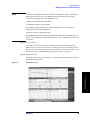
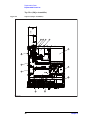
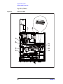
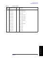
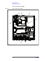
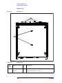
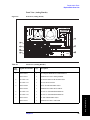
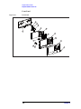
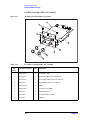
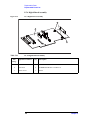
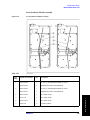
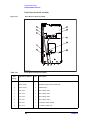
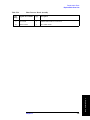
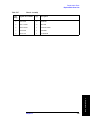
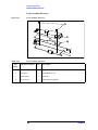
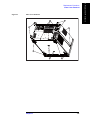
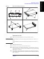
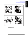
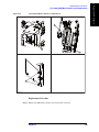
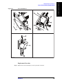
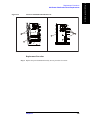
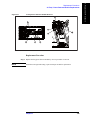
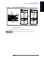
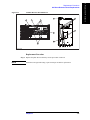
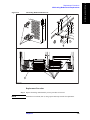
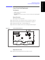
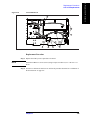
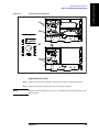
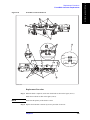
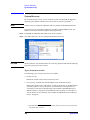
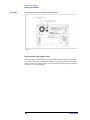
Refer to Figure 6-26 for this procedure.
Step 1. Remove the outer cover as described in “Outer Cover Removal” on page 136.
Step 2. Remove the front panel as described in “Front Panel Removal” on page 138.
Step 3. Remove the front panel cover as described in “Front Panel Cover Removal” on page 180.
Step 4. Remove the inverter assemby as described in “A52 Inverter Assembly Replacement” on
page 182.
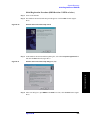
Step 5. Release the clamped cables from the clamps (item 1) on the LCD.
Step 6. Disconnect the cable (item 2) from the prove power.
Step 7. Remove the two TORX T10 screws (item 3) fastening the probe power and lift it (item 4).
Step 8. Remove the two TORX T15 screws (item 5) fastening the LCD to the front panel.
Step 9. Disconnect the cable (item 6) from the LCD.
184
Chapter 6