1
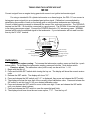
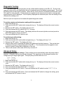
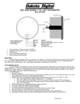
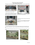
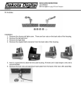
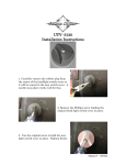
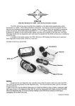
DSL-1 E DIESEL TACH INTERFACE UNIT This unit can provide a tachometer signal to drive a standard ignition system tachometer. The input signal can be from a tachometer output from the alternator, from a gear tooth sensor reading the flywheel teeth, or from an engine timing gear sensor. In addition to the setup mode calibration using gear tooth count, fine adjustment can be done during normal operation to fine tune the gauge needle position if needed. The + and – buttons allow fine adjustment to be performed with the engine running. Here is a general overview of the DSL-1’s control functions. Each of the different applications below will be described in detail starting on page 2 in this manual. Setup Set input mode: Select the input mode depending on your application. : alternator ‘W’ terminal tach signal : flywheel gear tooth sensor signal : timing gear tooth sensor signal 1. Begin with the key off. 2. Press and hold the SET switch while turning the key on. The display will show the current version code. 3. Release the SET switch. The display will show “”. 4. Press and release the SET switch. The current input mode will be shown, , , or . Press and release the INC switch to change the input mode. Press and release the SET switch to save it. 5. The CAL value will be set next. See the detailed instructions listed later in the manual for your specific application. Set output mode: Select the output gauge cylinder count. 4, 6, or 8 1. Begin with the key off. 2. Press and hold the SET switch while turning the key on. The display will show the current version code. 3. Release the SET switch. The display will show “”. 4. Press and release the INC switch until “” is displayed. 5. Press and release the SET switch. The current cylinder count will be shown, , , or . A 2000 rpm output signal will be generated reflecting the current cylinder count for gauge testing. 6. Press and release the INC switch to change it; press and release the SET switch to save it. 1 MAN# 650530 ALTERNATOR TACH INTERFACE UNIT : 12V Accessory Power INC + SET OUT 3 NORMAL DSL-1 E HI VOLT NOT USED SIGNAL IN SENSOR GND GROUND POWER DIESEL TACH INTERFACE dakotadigital.com For using a standard 4-6-8 cylinder tachometer on a diesel engine, the DSL-1 E can convert a signal from the ‘W’ terminal on an alternator and convert it into a tachometer signal for a standard gas ignition system tachometer. Not all alternators have a ‘W’ terminal. The unit is adjustable to allow for the different numbers of poles on the alternator as well as different pulley sizes on the engine and alternator. Calibration should be done using a light tach or another known reference for engine speed. The DSL-1 E has an adjustable range of 4.00 to 0.250. Calibration can be set using the setup mode and display or adjusted in real time while the engine is running. Wiring instructions are provided below. - 1/2 rate tach output standard tach output GROUND Sensor ground (not used) high voltage tach output jumper to HI VOLT output for some early Toyota tachometers Alternator 'W' terminal Determining required calibration ratio. It is easiest to begin with the CAL ratio set to 1.00. The new calibration ratio to make the tach read correctly is found using the equation below. (Actual RPM) (Tachometer reading) = calibration ratio Calibration Adjust with engine running: To increase the tachometer reading, press and hold the + push button switch. To decrease the tachometer reading, press and hold the - push button switch. Preset or adjust: The calibration value can be set from 0.250 – 4.00. 1. Begin with the key off. 2. Press and hold the SET switch while turning the key on. The display will show the current version code. 3. Release the SET switch. The display will show “”. 4. Press and release the INC switch until “” is displayed, then press and release the SET switch. 5. The display will show the ones digit of the currently stored calibration value. Press and release the INC switch to set this from 0. - 4. for your desired calibration value. 6. Once finished Press the SET switch to move to the tenths digit. Press and release the INC switch until your desired value is shown. 7. Press the SET switch to move to the hundredths digit. Press and release the INC switch until your desired value is shown. 8. Press the SET switch to save the hundredths digit. If the value is 1.00 or higher the calibration value will be saved. The calibration set is done. 9. If the value is 0.99 or lower the thousands digit will now be set. Press and release the INC switch until the desired value is shown. Press the SET switch to save and finish. 10. The display should now show the next menu option, “”. Turn the key off. 2 MAN# 650530 FLYWHEEL TACH INTERFACE UNIT : Convert a signal from a flywheel gear-tooth sensor to an ignition tachometer signal. 12V Accessory Power INC + SET OUT 3 NORMAL DSL-1 E HI VOLT NOT USED SIGNAL IN SENSOR GND GROUND POWER DIESEL TACH INTERFACE dakotadigital.com For using a standard 4-6-8 cylinder tachometer on a diesel engine, the DSL-1 E can convert a flywheel sensor signal into a standard gas ignition signal. Calibration is accomplished by determining the number of teeth on the flywheel or using another tachometer as a reference. An inductive, gear-tooth sensor such as Dakota Digital, Inc. part # 620008 should be mounted so the teeth pass by the end of the sensor. The GROUND terminal on the DSL-1 E should be connected to a good ground. The SIGNAL IN terminal will connect to one terminal from the sensor and the SENSOR GND terminal will connect to the other. Connect the POWER terminal to 12V accessory power. NORMAL terminal will provide the standard signal to the tachometer. If your tachometer will not read from this then try the HI VOLT terminal. - 1/2 rate tach output standard tach output GROUND high voltage tach output jumper to HI VOLT output for some early Toyota tachometers Gear tooth sensor Calibration Adjust with engine running: To increase the tachometer reading, press and hold the + push button switch. To decrease the tachometer reading, press and hold the - push button switch. Preset or adjust: The calibration value (tooth count) can be set from 32 – 254. 1. Begin with the key off. 2. Press and hold the SET switch while turning the key on. The display will show the current version code. 3. Release the SET switch. The display will show “”. 4. Press and release the INC switch until “” is displayed, then press and release the SET switch. 5. The display will show the hundreds digit of the currently stored calibration value. Press and release the INC switch to set this from 0-2 for your desired calibration value. 6. Once finished press and release the SET switch to move to the tens digit. Press and release the INC switch until your desired value is shown. 7. Press and release the SET switch to move to the ones digit. Press and release the INC switch until your desired value is shown. 8. Press and release the SET switch to save the ones digit and finish. 9. The display should now show the next menu option, “”. Turn the key off. 3 MAN# 650530 TIMING GEAR TACH INTERFACE UNIT : Convert a signal from an engine timing gear-tooth sensor to an ignition tachometer signal. 12V Accessory Power INC + SET OUT 3 NORMAL DSL-1 E HI VOLT NOT USED SIGNAL IN SENSOR GND GROUND POWER DIESEL TACH INTERFACE dakotadigital.com For using a standard 4-6-8 cylinder tachometer on a diesel engine, the DSL-1 E can convert a timing gear sensor signal into an a standard gas ignition signal. Calibration is accomplished by determining the number of teeth on the timing gear or using another tachometer as a reference. Consult a vehicle service manual to determine the sensor color code and connection. The GROUND terminal on the DSL-1 E should be connected to a good ground. The SIGNAL IN terminal will connect to the timing gear sensor signal. Connect the POWER terminal to 12V accessory power. NORMAL terminal will provide the standard signal to the tachometer. If your tachometer will not read from this then try the HI VOLT terminal. - 1/2 rate tach output standard tach output GROUND Sensor ground (not used) high voltage tach output jumper to HI VOLT output for some early Toyota tachometers Timing gear signal Calibration Adjust with engine running: To increase the tachometer reading, press and hold the + push button switch. To decrease the tachometer reading, press and hold the - push button switch. Preset or adjust: The calibration value (tooth count) can be set from 1 – 64. 1. Begin with the key off. 2. Press and hold the SET switch while turning the key on. The display will show the current version code. 3. Release the SET switch. The display will show “”. 4. Press and release the INC switch until “” is displayed, then press and release the SET switch. 5. The display will show the tens digit of the currently stored calibration value. Press and release the INC switch to set this from 0-6 for your desired calibration value. 6. Press and release the SET switch to move to the ones digit. Press and release the INC switch until your desired value is shown. 7. Press and release the SET switch to save the ones digit and finish. 8. The display should now show the next menu option, “”. Turn the key off. 4 Diagnostic Testing The basic power up and operation can be verified with the display on the DSL-1E. The dot in the upper left corner will be on steady when the unit is powered up and not getting a speed signal. The dot will be flashing when a tach signal is present. When the key if first turned on, the display will show the current CAL value for a few seconds. If both switches are pressed at the same time the current, incoming tach signal frequency will be displayed. If the frequency displayed has a decimal point, then the reading is kHz, otherwise the reading is Hz. Both the input and outputs can be tested with special diagnostic modes. To test the outputs and tachometer reading with the engine off: 1. Begin with the key off. 2. Press and hold the SET switch while turning the key on. The display will show the current version code. 3. Release the SET switch. The display will show “”. 4. Press and release the INC switch until “” is shown. 5. Press and release the SET switch. The display will show the current cylinder count and provide a 2000 RPM signal on OUT1 and OUT2. 6. Press and release the SET switch to quit. To test the input while driving: 1. Begin with the key off. 2. Press and hold the INC switch while turning the key on. The display will show “”. 3. Release the SET switch. The display will show “”. 4. Anytime either switch is pressed the display will update and hold the frequency. This can be done to determine the type of signal being fed to the DSL-1. This information can be supplied to tech support to assist in setup and configuration of the unit. 5. The unit will remain in this mode until the key is turned off. Advanced Setup Change input signal settings: These settings are set automatically when the setup mode is selected. If needed, they can be manually changed. The signal type can be changed between low voltage and high voltage signal types. The input pullup can be turned on or off. : or : or 1. Begin with the key off. 2. Press and hold the SET switch while turning the key on. The display will show the current version code. 3. Release the SET switch. The display will show “”. 4. Press and release the INC switch until “” is shown. 5. Press and release the SET switch. Press and release the INC switch to select “”, “”, or “”. 6. Press and release the SET switch. Press and release the INC switch to change the setting, press and release the SET switch to save it. 5 Trouble shooting guide Problem Tachometer will not work. lights are off. Tachometer will not work. dot is on steady. Tachometer will not work. dot is flashing. Tachometer will not read at low RPM. Tachometer will not read at high RPM. Tachometer will read when the engine is off Possible Cause No power to DSL1. Solution _ Check the power and ground terminals on the DSL-1. Should be 11-15 V dc. No input signal. Test for 1-20 volts AC at the signal in terminal with the engine running. DSL-1 set for wrong input Change the Setup – option. type. See instructions on page 1. Grounding interference. Make sure both the speed sensor and DSL-1 are grounded at the same point. Wrong output type. Try switching from normal output to the high voltage output. High voltage boost required. Use HI VOLT to drive gauge and jumper NOT USED terminal over to HI VOLT. DSL-1 set for wrong input Change the Setup – option to . type. See instructions on page 1. Tach signal is too low. Check sensor connections for ground problems or shorts. Test the ground connection between DSL-1 and sensor. Check for another device loading down the sensor. DSL-1 set for wrong input Change the Setup – option to . type. See instructions on page 1. Ignition wire too close to Route the sensor signal and ignition sensor signal wire. or injector wires away from each other to avoid interference. Signal In and OUT wires Route the input and output wires away routed too close. from each other to avoid feedback. Ground interference. Make sure the speed sensor and DSL-1 are grounded together. Sensitivity set incorrectly Change the Setup – option to . SERVICE AND REPAIR DAKOTA DIGITAL offers complete service and repair of its product line. In addition, technical consultation is available to help you work through any questions or problems you may be having installing one of our products. Please read through the Troubleshooting Guide. There, you will find the solution to most problems. Should you ever need to send the unit back for repairs, please call our technical support line, (605) 332-6513, to request a Return Merchandise Authorization number. Package the product in a good quality box along with plenty of packing material. Ship the product by UPS or insured Parcel Post. Be sure to include the RMA number on the package, and include a complete description of the problem with RMA number, your full name and address (street address preferred), and a telephone number where you can be reached during the day. Any returns for warranty work must include a copy of the dated sales receipt from your place of purchase. Send no money. We will bill you after repair. Dakota Digital Limited Lifetime Warranty DAKOTA DIGITAL warrants to the ORIGINAL PURCHASER of this product that should it, under normal use and condition, be proven defective in material or workmanship for the lifetime of the original vehicle it was installed in, such defect(s) will be repaired or replaced at Dakota Digital’s option. This warranty does not cover nor extend to damage to the vehicle’s systems, and does not cover removal or reinstallation of the product. This Warranty does not apply to any product or part thereof which in the opinion of the Company has been damaged through alteration, improper installation, mishandling, misuse, neglect, or accident. This Warranty is in lieu of all other expressed warranties or liabilities. Any implied warranties, including any implied warranty of merchantability, shall be limited to the duration of this written warranty. No person or representative is authorized to assume, for Dakota Digital, any liability other than expressed herein in connection with the sale of this product. 6