1
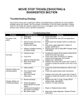
To Purchase This Item, Visit BMI Gaming | www.bmigaming.com | (800) 746-2255 | +1.561.391.7200
HORSE
PLAY
TM
OWNER’S MANUAL
Version 1.04
September 2005
BAY TEK GAMES INC.
1077 East Glenbrook Drive
Pulaski, WI 54162
E-mail: [email protected]
Web site: www.baytekgames.com
Service: ................... (920) 822-3951 ext. 1102
Parts: ...................... (920) 822-3951 ext. 1101
Fax: ......................................... (920) 822-8936
Service Fax: ........................... (920) 822-1496
Sales: ...................................... (920) 822-3951
To Purchase This Item, Visit BMI Gaming | www.bmigaming.com | (800) 746-2255 | +1.561.391.7200
TABLE OF CONTENTS
Safety Precautions ................................. 1
How the Game Works ............................ 1
Service Connections .............................. 2
Unpacking, Assembly and Installation.... 2
Hardware ............................................ 2
Assembly ............................................ 2
Sounds................................................... 6
Counters ................................................ 6
Rubber Balls .......................................... 6
Gen 5 Main Board Schematics ............ 24
Communications – Serial EEprom ....... 25
Input Section A – Configuration Switches
............................................................. 26
Input Section B – Inputs RE, RC ......... 27
Output Section A – Chase Lights, Q13 Q16...................................................... 28
Output Section B – Q17 – Q24 ............ 29
Output Section C – Q5 – Q12.............. 30
Power Section ..................................... 31
Processor Section – Input RD ............. 32
PROGRAMMING SECTION...................... 8
SPARE PARTS – HORSE PLAY............ 33
Programmable Dipswitches ................... 8
Group S1 Dipswitches ........................ 9
Group S2 Dipswitches ...................... 10
Ticket Patterns.................................. 11
TECHNICAL SUPPORT ......................... 35
PREVENTIVE MAINTENANCE SECTION
................................................................ 12
NOTES.................................................... 38
OPERATION AND SETUP SECTION....... 1
Maintenance Chart............................... 12
TROUBLESHOOTING & DIAGNOSTICS
SECTION................................................. 13
Troubleshooting Strategy ..................... 13
Diagnose Power Supply....................... 15
SERVICE AND REPAIR SECTION......... 16
Firing Solenoid Replacement ............... 16
Lift Cylinder Control Valve Replacement
............................................................. 16
Ball Sorter Gearmotor .......................... 17
Teeth Reset Gearmotor Replacement . 17
Circuit Boards and Sensors ................. 18
ELECTRICAL DRAWINGS SECTIONS.. 19
12 Volt Jumper Cable (J1) Connector .. 19
Volume Cable (J2) Connector.............. 19
Jumper (J3) Connector ........................ 20
Jumper (J4) Connector ........................ 21
Jumper (J5) Connector ........................ 22
Connectors........................................... 23
Horse Play™
WARRANTY INFORMATION ................. 36
REPAIR RECORD .................................. 37
To Purchase This Item, Visit BMI Gaming | www.bmigaming.com | (800) 746-2255 | +1.561.391.7200
OPERATION AND SETUP SECTION
Safety Precautions
this manual. See Programming Section on page
8 for dipswitch settings.
CAUTION: Electrical Shock
Hazard.
Do not perform maintenance
or repair of this equipment
with power ON. Unplug the
unit from the wall outlet or shut off power at
the power strip inside the cabinet.
CAUTION: Electrical Shock
Hazard.
Always plug game into a
grounded circuit.
WARNING: Use of flammable
substances can cause severe
burns or personal injury.
Always use non-flammable
solvents for cleaning parts and
surfaces of this game. Do not use flammable
substances such as gasoline, kerosene or
thinners.
How the Game Works
Horse Play is a game of skill and good aim. The
player shoots black rubber balls attempting to
knock out the horse’s teeth. Each knockout
increases the number of tickets won and
dispensed at the end of the game.
Figure 1 Game Target
The owner can set the number of balls per coin,
coins per play, ticket payout, free play and
more. See Programming Section on page 8.
The teeth must be knock fully backward. Hitting
the teeth and slightly moving them will not score
a hit. There is a 2.5 second delay before each
ball can be shot. If the game does not register a
shot after three minutes, the game ends and all
credits clear.
NOTE: The score table (Standard or New
Jersey), which is determined by setting the
dipswitches, should match the Knock Down
Tickets decal on the game Panel (Figure 2).
Additional sets of numbers are included with
Horse Play™
Figure 2 Knock Down Panel
1
To Purchase This Item, Visit BMI Gaming | www.bmigaming.com | (800) 746-2255 | +1.561.391.7200
Figure 3 Installation Hardware and Screw Bit
Service Connections
This game requires a pneumatic air supply with
a minimum air pressure of 85 psi (5.86 bars).
Bay Tek
offers two portable compressor
models, a 13 gallon (p/n A5AC1002) and a 20
gallon (Recommended) (p/n A5AC1003). Bay
Tek supplies a 3/8”-1/2” pipe reducer for the air
hose connection. Customers must supply any
other needed fittings and piping.
All Bay Tek games are 110V or 220V(optional)
and draw 2-3 amps at startup. Outlets should
be rated for 20 amps or higher.
IMPORTANT: Be sure that the electrical power
outlets match the game requirements. See
outlet labeling at rear bottom of game cabinet.
Unpacking, Assembly and
Installation
Hardware
The installation kit consists of:
(6) 1/4 – 20 x 1-1/4” Bolts and plain washers
(8) 1/4 – 20 x 1” Bolts and plain washers
(54) #10 x 5/8 Black wood screws
(4) #10 – 24 x 1/2 Black self-tapping screws
(2) #10 – 32 Nylon Locknuts
(1) Square bit (driver)
(4) Connector plates (yellow)
(12) Black balls
(1) 3/8” to 1/2" Pipe Reducer
(1) Owner’s Manual
(6) #8 Black screws
1/4 –20 X 1” LG.
1/4 –20 X 1-1/4” LG.
#10 x 5/8 WOOD SCREW
#10 – 32 LOCKNUT
Horse Play™
#10 x 1/2 SELF TAPPING
BIT
Inspect hardware package to insure all needed
material is there and identified.
Assembly
1. Inspect the game for any damaged, loose or
missing parts. If damage is found please
contact the carrier first. Then contact Bay Tek
at: [email protected], or phone (920)
822-3951 to order replacement parts.
CAUTION:
Lifting
Hazard.
Lifting heavy objects can cause
back, neck and other injuries.
Be sure adequate lifting and
moving devices are available
when unloading, unpacking and moving this
game.
The game is shipped with four primary cabinet
Assemblies, stools and metal ball screens. The
cabinets are identified as the Target (rear)
cabinet, Ramp (middle) cabinet, Shooting
(front) cabinet and the Marquee.
2. Place the rear cabinet near or at its final
location.
3. Open the rear cabinet door, uncoil the power
cord and feed the cord through the hole under
the door opening. Do not plug the power cord
into the wall outlet at this time.
4. Uncoil other wiring cables.
5. Place the middle cabinet in front of and
close to the rear cabinet. Feed the white phone
cable from the rear cabinet through the middle
cabinet. Plug the middle cabinet power cable
into the power strip located on the back wall of
the rear cabinet. See Figure 4. Plug the lights
and target cable connectors into the matching
connectors from the middle cabinet.
NOTE: The cables in the middle cabinet are
universal cables therefore the number and color
of wires does not matter. Match connector size
only. See Figure 5
2
To Purchase This Item, Visit BMI Gaming | www.bmigaming.com | (800) 746-2255 | +1.561.391.7200
6. Using the #8 black screws attach the score
box to the middle cabinet.
a. Install the middle screen by placing it
over the two threaded studs on the ball
grate. Secure with two #10-32 nylon
locknuts. See Figure 7.
Figure 4 Power Strip with Circuit Breaker
Figure 5 Wire Harness from front cabinet
6. Push the middle and rear cabinets together.
Be careful not to pinch any wiring. Secure with
two connector plates and four 1/4-20 x 1” bolts
and plain washers.
Figure 6 Connector Plates w/ 1/4 - 20 x 1" Bolts
7. Installing the middle metal screens.
Horse Play™
3
To Purchase This Item, Visit BMI Gaming | www.bmigaming.com | (800) 746-2255 | +1.561.391.7200
the rear cabinet. Continue with six #10 x
5/8” wood screws in the remaining holes.
#10 – 24
SELF-TAPPING
SCREWS
Figure 7 Installing Middle Screen
b. Attach the rear vertical frame of the
middle screen to the cabinet with four black
#10 x 5/8” wood screws.
#10 X 5/8 SCREWS
c. Attach the front of the screen to the
sloped surface with two black #10 x 5/8”
wood screws.
d. The grates in the bottom of the middle
cabinet attach to the rear cabinet with six
black #10 x 5/8” wood screws.
Figure 8 Side Screen
#10 x 5/8 SCREWS
8. Installing the outside metal screens. See
Figure 8. The outside screens are marked
left and right. Place the screens on the
middle cabinet frame and push tight up
against the rear cabinet.
1/4” X 1-1/4” BOLTS / WASHERS
a. Secure the vertical legs of the screens
to the front of the middle cabinet with
sixteen black #10 x 5/8” wood screws.
Secure the screen to the horizontal edge of
the cabinet with six black #10 x 5/8” wood
screws through holes on the inside of the
screen frame.
b. Install the two yellow top rails which
overlap the tops of the outside screens and
the rear cabinet. Attach the front of the rails
to the screens using four black #10-24 x
1/2" self-tapping metal screws. At the back
of each rail, use a 1/4-20 x 1-1/4” bolt with a
plain washer screwed into recessed nuts in
Horse Play™
Figure 9 Installing Top Rails
9. Installing the Marquee.
a. Position the marquee on top of the
yellow rails and pass the power cord and
wire bundle through the hole and into the
rear cabinet. Plug the power cord and
4
To Purchase This Item, Visit BMI Gaming | www.bmigaming.com | (800) 746-2255 | +1.561.391.7200
speaker wire into connectors in the rear
cabinet.
#10 - 5/8 SCREWS
1/4 – 20 x 1-1/4” BOLT / WASHER
Figure 10 Marquee Cables
b. Secure the marquee to the rear cabinet
with four 1/4-20 x 1-1/4” bolts and plain
washers screwed into recessed nuts. See
Figure 9.
c. Secure the marquee to the middle
screen with two #10 x 5/8” wood screws.
#10 x 5/8 SCREWS
Figure 11 Middle Screen Attachment
Figure 12 Installing Marquee
10. Install the shooting cabinet.
a. Tip the cabinet to align and install the
dowel pins in the stool bases with holes in
the bottom of the cabinet.
b. Position the front cabinet near the
middle cabinet. Uncoil and pull the air hose
through the middle cabinet and out the hole
in the bottom of the rear cabinet.
NOTE: The cables in the middle cabinet are
universal cables therefore the number and
color of wires does not matter. Match
connector size only.
c. Plug all cable connectors from the
middle cabinet into plugs in the front
cabinet. Plug the white phone cable into left
cable socket on the main board.
d. Attach the marquee to the yellow rails
using four #10 x 5/8” wood screws.
LEFT CABLE
SOCKET
Figure 13 Socket location on Main Board
Horse Play™
5
To Purchase This Item, Visit BMI Gaming | www.bmigaming.com | (800) 746-2255 | +1.561.391.7200
11. Push the front and middle cabinets together.
Be careful not to pinch any wiring.
12. Lock the front and middle cabinets together
with two connecting plates. Secure each plate
with two 1/4-20 x 1” bolts and plain washers.
13. At the rear of the cabinet, attach the air
hose to the building’s air supply or portable air
compressor. Set the air pressure at the
regulator for 70 psi (4.83 bars). See Service
Connections on page 2 for more information.
14. Fill the ticket tray in the front door panel.
The ‘Low’ Ticket light will illuminate when there
is approximately a 1/2" stack of tickets left in the
ticket dispenser bin.
18. Once everything is set and working
properly, close and lock the front and rear door
panels.
19. Clean all surfaces of the game with mild
soap and water. Do not use solvents to clean
the game decal surfaces. The game is now
ready to play.
Sounds
An audio chip provides music and other
sound effects as play progresses to enhance
the visual effects of the game. A volume
control is located on the inside of the front
door panel.
Counters
LOW
TICKET
LIGHT
Two counters are mounted on the inside of the
front door panel. One counter tracks the
number of games played and the other counter
tracks the total number of tickets dispensed.
The counters cannot be reset.
Figure 14 Low Ticket Light
15. Plug in the power cord into the wall outlet
and turn on the power strip at the bottom of the
rear cabinet.
16. Place the 12 black balls, shipped with this
game, in the return chute.
NOTE: The game is shipped with balls loaded
in the lift tube. In the event new balls must be
loaded, the easiest way is to drop them down
the gun barrel. Sixteen (16) balls are needed in
the lift tube.
17. Test the game. If something is not working
properly, review the troubleshooting section
first. If the problem cannot be resolved, contact
the Bay Tek service department at:
[email protected], or phone (920)
822-3951.
Horse Play™
Figure 15 Game Counters and Volume Control
Rubber Balls
The black rubber balls are coated with teflon®
to increase the life of the ball. While very
durable, the coating will eventually wear off and
the rubber material will then begin to wear
rapidly. As the balls wear down they will not
provide a good seal in the firing tube and poor
6
To Purchase This Item, Visit BMI Gaming | www.bmigaming.com | (800) 746-2255 | +1.561.391.7200
firing and miss-fires will occur. This can be
corrected somewhat by increased air pressure
to the fire cylinder but at some point it will be
necessary to replace the balls due to wear.
NOTE: The game is shipped with balls loaded
in the lift tube. In the event balls must be
loaded, the easiest way is to drop them down
the gun barrel. Sixteen (16) balls are needed in
the lift tube.
Ball Removal
WARNING: The ball chute air cylinder can
pinch, cut or sever fingers during ball
removal.
Insure air pressure is OFF and system
pressure is released before attempting to
remove balls from the lift system.
AIR SHUT-OFF
Turn off the air supply shut off valve located in
the front cabinet. Release the air system
pressure by firing the gun once. Remove the
spring from the pawl that supports the balls in
the tube and pull the pawl back out of the way.
Use a short stick to push the balls out into the
chute where they can be removed.
Horse Play™
7
To Purchase This Item, Visit BMI Gaming | www.bmigaming.com | (800) 746-2255 | +1.561.391.7200
PROGRAMMING SECTION
The number of coins required for each game
credit, free play, number of balls per credit,
tickets payout, etc., are programmable by
dipswitches located on the main circuit board.
Programmable Dipswitches
The main circuit board is located on the inside
back wall of the cabinet. Be sure power is off
before setting these switches.
Figure 16 Location of dipswitches on Main Circuit
Board
IMPORTANT: Power must be OFF to the game when setting dipswitches. Turn OFF the power strip
inside the cabinet. Set the dipswitches to the desired settings, wait 30 seconds and then turn ON power
at the power strip.
MAIN BOARD
S1
ON
Horse Play™
1 2
3 4
5 6
7 8
ON
1 2 3
S2
4 5
6 7
8
8
To Purchase This Item, Visit BMI Gaming | www.bmigaming.com | (800) 746-2255 | +1.561.391.7200
Group S1 Dipswitches
Sets the Ticket Pattern Number. The
Ticket Pattern Number corresponds with
the ticket pattern tables on page 11.
Sets the Number of Balls per game
credit.
Note: The time between shots is 2.5
seconds and cannot be changed.
Not used on this game and should
remain in the disabled/OFF position.
Sets the Attract Mode. During ‘Attract’
mode the audio will play select tracks
from the audio bank embedded in the
software.
Not used on this game and should
remain in the disabled/OFF position.
* Indicates the factory default setting.
Value
or Mode
1
2
3
1
OFF
OFF
OFF
2
OFF
OFF
ON
3
OFF
ON
OFF
4
OFF
ON
ON
5
ON
OFF
OFF
6*
ON
OFF
ON
7
ON
ON
OFF
8
ON
ON
ON
4
5
6*
OFF
OFF
5
OFF
ON
4
ON
OFF
3
ON
ON
7
8
OFF
Disable *
Enabled*
ON
OFF
Disabled
OFF
Disable *
S1
ON
Horse Play™
6
1 2 3 4 5 6 7
8
9
To Purchase This Item, Visit BMI Gaming | www.bmigaming.com | (800) 746-2255 | +1.561.391.7200
Group S2 Dipswitches
Sets the number of Coins Per Credit.
Determines the number of coins
required per game credit. Each credit
allows the player to shoot the number
of balls determined by Group S1
switches 1,2,3. The Free Play position
allows the operator to set up
demonstrations, etc. without inserting
coins.
Not used on this game and should
remain in the disabled/OFF position.
Sets the Table Option. Allows the
operator to choose between the
‘Standard’ or ‘New Jersey’ Ticket
Pattern Tables.
Clear EPROM Option. Allows the
operator to clear all game credits,
tickets owed, etc.
Must follow this procedure; 1, Turn Off
power. 2. Set switch to ON. 3, Turn ON
power. 4. Wait for all items to clear. 5.
Turn OFF power. 6. Set switch to OFF.
7. Turn ON power.
Not used on this game and should
remain in the disabled/OFF position.
* Indicates the factory default setting.
Value or
Mode
1
1Coin *
OFF
OFF OFF
2 Coins
OFF
OFF
ON
3 Coins
OFF
ON
OFF
4 Coins
OFF
ON
ON
5 Coins
ON
OFF
OFF
6 Coins
ON
OFF
ON
Free Play
ON
ON
OFF
8 Coins
ON
ON
ON
Disable *
2
3
4
6
7
8
OFF OFF
New Jersey
ON
Standard *
OFF
Enable
ON
Disable *
OFF
OFF
Disable *
S1
ON
Horse Play™
5
1 2 3 4 5 6 7
8
10
To Purchase This Item, Visit BMI Gaming | www.bmigaming.com | (800) 746-2255 | +1.561.391.7200
Ticket Patterns
STANDARD (BANK 2, DIP 6 OFF)
PATTERN #
TEETH KNOCKED DOWN
1
2
3
4
5
6
7
8
0
1
1
2
3
3
4
4
0
1
1
1
2
3
3
4
4
0
2
2
2
4
4
5
6
8
0
3
2
2
4
4
5
6
8
0
4
3
5
6
5
7
8
10
0
5
3
5
6
5
7
8
10
0
6
4
6
8
6
9
10
12
0
NEW JERSEY (BANK 2, DIP 6 ON)
PATTERN #
Horse Play™
TEETH KNOCKED DOWN
1
2
3
4
5
6
7
8
0
1
2
3
4
5
6
7
8
1
1
2
3
4
5
6
7
8
2
1
2
3
4
5
6
7
8
3
1
2
3
4
5
6
7
8
4
1
2
3
4
5
6
7
8
5
1
2
3
4
5
6
7
8
6
1
2
3
4
5
6
7
8
11
To Purchase This Item, Visit BMI Gaming | www.bmigaming.com | (800) 746-2255 | +1.561.391.7200
PREVENTIVE MAINTENANCE SECTION
Maintenance Chart
Use the following maintenance schedule as a
guide only. Actual maintenance intervals will
depend on usage and environmental conditions
at the location of the game.
Keep a log of all inspections, even if no problem
exists, with date and time of inspection, action
taken.
A sample Repair Record form is
included at the end of this manual.
This game does not require any lubrication
however periodic cleaning is required.
IMPORTANT: Do not use cleaning solvents on
game graphics. Use only a mild soap solution
and dry with a clean lint free cloth.
IMPORTANT: The game should be shut OFF
for cleaning and maintenance.
Daily
Inspect air system and insure pressure is set between 40 psi
and 50 psi.
Inspect game for physical damage. Repair as necessary.
Check all game lighting. Repair/replace as necessary.
Clean outside surfaces and stools. Balls leave black marks
on surfaces.
Fill ticket tray.
Empty coin tray.
Clean/vacuum the ball return area.
Open game and clean inner surfaces as necessary.
Play game to insure it is working properly.
Check to insure proper number of balls are in the game.
Check balls for wear and damage. Note: As the balls wear
some adjustment of the ball lift cylinder air pressure may be
required. See Service and Repair on page 16.
Blow paper dust from ticket mechanism
Check all hardware for tightness.
If using non-filtered air, dump air pressure then remove and
drain water from hoses.
Clean gun barrel with compressed air.
Horse Play™
Weekly
Monthly
X
X
X
X
X
X
X
X
X
X
X
X
X
X
X
12
To Purchase This Item, Visit BMI Gaming | www.bmigaming.com | (800) 746-2255 | +1.561.391.7200
TROUBLESHOOTING & DIAGNOSTICS SECTION
Troubleshooting Strategy
Use common sense and a systematic method of troubleshooting to determine the exact problem,
probable cause and remedy. Use the process of elimination to find the faulty component. Always check
for the simple and obvious causes first such as unplugged, loose or broken wires and bad sensors,
bent, pinched, stuck or jammed components.
Troubleshooting Chart
Problem
Probable Cause
No power to the game.
a. Unplugged.
b. Blown fuse
c. Game circuit breaker
tripped.
d. Building circuit breaker
tripped.
e. Power supply faulty.
Guns won’t shoot balls.
a.
b.
c.
d.
Air pressure is good but
balls do not shoot.
a.
Balls misfire or shoot
two at a time.
Ball lift system not
working properly.
Hits do not score.
No air pressure.
Air pressure too low.
Trigger not working.
Balls worn too much.
Not enough balls or no
balls in lift chute.
b. Balls stuck in return chute
or lift chute.
c. Balls worn too much and
do not provide proper
height in the lift tube.
a. Ball height problem.
b. Bent lifter tube.
a. Air pressure needs
adjustment to lift cylinder.
b. Solenoid bad.
a. Target sensor not
working.
b. Cable bad.
Remedy
a. Check wall outlet.
b. Check transformer fuse (220 volt
applications only).
c. Reset power strip breaker switch on
inside rear wall.
d. Check building circuits.
e. Diagnose power supply as described
in the following section.
a. Turn on air compressor.
b. Set air pressure to 70 to 80 psi (4.83
– 5.52 bars).
c. Check continuity to trigger switch and
to fire solenoid.
d. Replace balls.
a. Check for proper number of balls in
game.
b. Clear all jams.
c. Replace worn balls.
a.
b.
a.
b.
a.
b.
Horse Play™
Check for worn balls. Replace with
new balls.
Straighten out tube.
Adjust air pressure to both ends of
the lift cylinder.
Check continuity between lifter
solenoid and main circuit board.
Replace solenoid if bad.
Check alignment of emitter and
detector for that tooth. Replace as
necessary.
Check continuity between sensor
and main circuit board.
13
To Purchase This Item, Visit BMI Gaming | www.bmigaming.com | (800) 746-2255 | +1.561.391.7200
Troubleshooting Chart
Problem
Probable Cause
Remedy
a. Replace fuse located in the wiring
near the main circuit board.
b. Replace gearmotor assembly.
c. Check the linkage between the reset
arm and gearmotor. Check connector
cam setscrew on the gearmotor.
a. Check continuity of wiring to sensor
from main board.
b. Replace sensor.
Teeth won’t reset.
a. In-line fuse blown.
b. Gearmotor bad.
c. Linkage problem.
Teeth reset bar rotates
up multiple times.
a. Bad wiring.
b. Faulty sensor.
No Audio.
a. Volume too low.
b. Loose wire.
c. Main circuit board
malfunction.
Lighting not working
properly.
Tickets do not dispense.
a.
b.
a.
b.
Burned out lights.
Cable problem.
Faulty cable to dispenser.
Faulty cable to main circuit
board.
c. Ticket dispenser not
working.
d. Main circuit board
malfunction.
a. Replace bulbs.
b. Check and repair wiring.
a. Check wiring continuity. Check for
pinched, broken or disconnected
cable. Replace as necessary.
b. Check wiring continuity. Check for
pinched, broken or disconnected
cable to main circuit board.
c. Replace dispenser with spare working
dispenser.
d. Replace main board with a spare Gen
5 board if possible to isolate the
problem to the main circuit board.
Wrong number of tickets
dispensed.
a. Ticket Pattern or Ticket
Table dipswitches set
wrong.
b. Dirty opto-sensor on ticket
dispenser.
c. Faulty ticket dispenser.
d. Main circuit board
malfunction.
a. Check and reset dipswitches.
b. Clean with compressed air and if
necessary wipe with isopropyl alcohol
on a cotton swab.
c. Replace with spare working
dispenser.
d. Replace main board with a spare Gen
5 board if possible to isolate the
problem to the main circuit board.
Horse Play™
a. Increase the volume at the volume
control at the inside of the front door
panel.
b. Check audio cable connections to
speaker, volume control and main
circuit board.
c. Replace main board with a spare Gen
5 board if possible to isolate the
problem to the main circuit board.
14
To Purchase This Item, Visit BMI Gaming | www.bmigaming.com | (800) 746-2255 | +1.561.391.7200
Diagnose Power Supply
Use the following procedure to check the power
supply for Gen 5 games.
12 V OUT
Check the small green LED light on the power
supply circuit board. If the light is out there is a
short somewhere. If the light dims, there is an
overload in one of the circuits such as a bad
solenoid.
Turn power OFF. Disconnect all 12 volt
output wires only. Turn power ON.
Green LED Light
comes ON.
Green LED Light
remains OFF.
LIGHT
Figure 17 Power Supply
Replace Power
Supply.
Turn power OFF. Unplug all outputs from the Gen 5 Main Board.
Reconnect the 12 volt output wires to the Power Supply. Turn power
ON.
Green LED Light
comes ON.
Turn power OFF.
Reconnect the outputs
at the Main Circuit
Board one at a time.
Wait 3 minutes
between tests to turn
power ON.
Green LED Light
comes ON.
Horse Play™
Green LED Light
remains OFF.
Short in Main Board
- Replace.
Green LED Light
remains OFF.
Green LED Light
dims.
That cable is OK.
That cable or related
component is shorted out.
See Jumper Cable Pin-Outs
to see which component might
be at fault.
A related component such as
a solenoid is causing an
overload. See Jumper Cable
Pin-Outs to see which
component might be at fault.
15
To Purchase This Item, Visit BMI Gaming | www.bmigaming.com | (800) 746-2255 | +1.561.391.7200
SERVICE AND REPAIR SECTION
CAUTION: Static electricity
could harm circuit boards
and processor chips. Always
ground yourself by cable or
by touching metal surfaces
prior to removing or servicing electronic
equipment in this game. Avoid working on
carpeted surfaces.
attached to which terminal. Turn on the
power and test the unit.
Lift Cylinder Control Valve
Replacement
The directional control valve and solenoid are
replaced together.
CAUTION: Electrical Shock
Hazard.
Do not perform maintenance
or repair of this equipment
with power ON. Unplug the
unit from the wall outlet or shut off power at
the power strip inside the cabinet.
Firing Solenoid Replacement
AIR CONTROL VALVE
SHUT-OFF
VALVE
Shut off power to the game at the power strip
located in the rear ‘target’ cabinet.
1. Remove the two wire clips from the
solenoid.
2. Remove the hex nut holding the solenoid to
the quick release valve.
AIR REGULATOR
Figure 19 Air Controls
1. Shut OFF air pressure at the air shut-off
valve or the air regulator. Release system
pressure by firing the guns.
2. Disconnect the three air lines in to and out
of the control valve.
3. Disconnect the wiring connector from the
solenoid. Remove the mounting screws and
remove from the game.
4. Install the new plug, re-attached the wire
connector from the solenoid and re-attached
the air lines.
Figure 18 Ball Firing Solenoid
5. Return power and air pressure to the game
and test by firing the gun several times to
insure that the balls are being loaded
properly into the lift tube.
3. Install the new solenoid and re-attach the
wires. It doesn’t matter which wire is
Horse Play™
16
To Purchase This Item, Visit BMI Gaming | www.bmigaming.com | (800) 746-2255 | +1.561.391.7200
Ball Sorter Gearmotor
The ball sorter gearmotor assembly, in the
middle cabinet, oscillates the paddles for the
ball return chutes to keep the balls from
becoming jammed in the chutes. Replace as
follows.
6. Reconnect the wire connector.
7. Slide the two cabinets together, being
careful not to pinch any wiring, and secure
with the two connector plates.
Teeth Reset Gearmotor
Replacement
CAM
REMOVE CAM
SETSCREW
LOCKNUTS
Figure 20 Ball Sorter Gearmotor
1. Remove the four bolts and washers from
the two connector plates holding the front
and middle cabinets together. Slide the front
cabinet away from the middle cabinet
slightly to gain access to the gearmotor
assembly.
2. Pull the two wires up out of the hole in the
frame to expose the connector. Unplug the
connector.
3. Remove the setscrew holding the connector
cam assembly to the gearbox shaft and pull
the cam off the shaft.
4. Remove the four locknuts that secure the
gearmotor assembly to the frame.
5. Install the new gearmotor assembly with the
four locknuts. The hole in the connector
cam is flat on one side so the gearbox shaft
may have to be rotated slightly to allow the
cam to be installed. Secure with the
setscrew.
Horse Play™
FOUR LOCKNUTS
Figure 21 Propeller Motor
1. Open the access door in the rear cabinet
and unplug the gearmotor wiring at the
connector.
2. Pull the tooth reset arm downward to
manually rotate the connector cam to gain
access to the setscrew. Loosen the
setscrew and remove the cam from the
shaft.
3. Remove the four locknuts mounting the
motor/gearbox assembly in the mounting
frame. Remove the gearmotor assembly
from the game.
4. Install the new gearmotor and secure with
the four locknuts.
8. Install the connector cam assembly onto the
motor shaft and secure with the setscrew.
The hole in the connector cam is flat on one
side so the gearbox shaft may have to be
17
To Purchase This Item, Visit BMI Gaming | www.bmigaming.com | (800) 746-2255 | +1.561.391.7200
rotated slightly to allow the cam to be
installed. Secure with the setscrew.
5. Reconnect the wire connector.
Circuit Boards and Sensors
Target Score Sensors
The score sensors are mounted to a small
circuit board and consist of an emitter and a
detector on opposite sides of the target flag. To
replace the sensor board;
1. Carefully unplug all wiring connectors.
2. Remove the four Phillips head screws at the
four corners of the board and remove the
board from the mounting panel.
3. Before installing the new board, check to be
sure that the dipswitches are set in the
same position as the old board.
NOTE: If swapping the circuit board with a
spare Gen 5 board for testing purposes, be
sure to also swap out the software chip. Use
extreme care to prevent static electricity and to
prevent bending socket pins.
4. Install the board and reconnect the wiring
connectors and the white display cable.
UNPLUG HERE
TWO MACHINE BOLTS
Figure 22 Target Score Sensors
1. Open the access door of the rear cabinet
and unplug the sensor wiring at the
connectors on the sensor circuit board.
2. Unbolt the sensor boards.
3. Replace the sensor boards and reconnect
the wire cables.
SOFTWARE CHIP
Figure 23 Main Circuit Board Replacement
5. Re-test the game.
4. Test the sensors by moving the tooth so the
tooth flag no longer blocks the sensors and
scores a hit.
Main Circuit Board
Replacing the main Gen 5 circuit board.
Horse Play™
18
To Purchase This Item, Visit BMI Gaming | www.bmigaming.com | (800) 746-2255 | +1.561.391.7200
ELECTRICAL DRAWINGS SECTIONS
J1
View Direction
DISPLAY
& CHASE
J3
J4
J5
All
connector
drawings
are as
Viewed
from the
pin out
position.
J2
DIPSWITCHES
Figure 24 Typical Gen 5 Main Board
12 Volt Jumper Cable (J1)
Connector
Volume Cable (J2) Connector
PIN – OUT
PIN – OUT
IN FROM
POWER
SUPPLY,
TO MAIN
BOARD
12 VOLT
INPUT
WHITE
12 VOLT
GROUND
GREEN
12 VOLT
INPUT
WHITE
RIGHT AUDIO
OUTPUT
GREEN
LEFT AUDIO
OUTPUT
BLACK
RIGHT AUDIO
GROUND
RED
LEFT AUDIO
GROUND
WHITE
12 VOLT
GROUND
GREEN
Horse Play™
19
To Purchase This Item, Visit BMI Gaming | www.bmigaming.com | (800) 746-2255 | +1.561.391.7200
Jumper (J3) Connector
PIN - OUT
LEFT GAME TRIGGER GROUND
WHITE
LEFT GAME TRIGGER
RED
RIGHT GAME ‘LO’ SIGNAL
WHITE
UNUSED
TAN
GREEN
RIGHT GAME TRIGGER
BLACK
LEFT GAME ‘LO’ SIGNAL
GREEN
UNUSED
ORANGE
UNUSED
UNUSED
GREY
PINK
TOOTH # 1
RED
TOOTH # 3
BLUE
TOOTH # 5
GREEN
RIGHT RACK HOME SENSOR
YELLOW
Horse Play™
RIGHT GAME TRIGGER GROUND
TOOTH # 2
WHITE
TOOTH # 4
BROWN
TOOTH # 6
BLACK
LEFT RACK HOME SENSOR
PURPLE
20
To Purchase This Item, Visit BMI Gaming | www.bmigaming.com | (800) 746-2255 | +1.561.391.7200
Jumper (J4) Connector
Control Box Cable
PIN – OUT
GAME METER SIGNAL
BROWN
COUNTER POWER +12V
PINK
R. GAME COIN DOOR +12V
ORANGE
TICKET METER SIGNAL
TAN
GROUND
GREEN
LEFT GAME COIN IN
GRAY
RIGHT GAME COIN IN
GRAY
GROUNDS/ LEFT DISPENSER
GROUND
GREEN & 2 BLACK
"Lo" TICKET GROUNDS
2 YELLOW
LEFT GAME DISPENSER
ENABLE
WHITE
RIGHT GAME DISPENSER
GROUND
BLACK
RIGHT GAME
DISPENSER ENABLE
WHITE
Horse Play™
LEFT GAME DISPENSER
NOTCH SIGNAL
BLUE
LEFT DISPENSER +12V
RED
LEFT COIN DOOR +12V
ORANGE
RIGHT GAME DISPENSER
NOTCH SIGNAL
BLUE
RIGHT GAME DISPENSER
+12V
RED
21
To Purchase This Item, Visit BMI Gaming | www.bmigaming.com | (800) 746-2255 | +1.561.391.7200
Jumper (J5) Connector
PIN - OUT
UNUSED
RED
LEFT RESET MOTOR
ORANGE
*HAS INLINE FUSE
UNUSED
WHITE
RIGHT RESET MOTOR
GRAY
*HAS INLINE FUSE
LEFT GAME, LO TICKET LIGHT
BLUE
UNUSED
PINK
RIGHT GAME, LO TICKET LIGHT
BROWN
UNUSED
TAN
UNUSED
GREEN
RIGHT GAME LIFT
SOLENOID
BLACK
LEFT RACK OUTPUT
BLACK
RIGHT RACK
OUTPUT
RIGHT GAME FIRE
SOLENOID
GREEN
LEFT GAME LIFT SOLENOID
BLACK
YELLOW
UNUSED
PURPLE
Horse Play™
LEFT GAME FIRE SOLENOID
BROWN
22
To Purchase This Item, Visit BMI Gaming | www.bmigaming.com | (800) 746-2255 | +1.561.391.7200
Connectors
View Direction
The cables and connectors used in the ramp
“middle” section are universal therefore the
number and color of wires does not matter.
Match size of connector only. Below is a
diagram showing the Inputs to that cable from
the target cabinet.
TARGET - OUTPUTS
1
BROWN
LEFT
MOTOR
BLACK
LEFT LOW
TICKET
X
X
X
BLACK
RIGHT
LOW
TICKET
X
X
RED
RIGHT
RACK
BROWN
RIGHT
MOTOR
X
RED
LEFT RACK
X
X
+
13
3
15
TARGET - INPUTS
2 GRAY
2 BLUE
TOOTH 1
TOOTH 4
2 WHITE
2 PURPLE
TOOTH 2
TOOTH 5
2 ORANGE
2 YELLOW
TOOTH 3
TOOTH 6
Horse Play™
GREEN
RIGHT
RACK
SENSOR
X
X
GREEN
LEFT RACK
SENSOR
X
X
X
X
X
23
To Purchase This Item, Visit BMI Gaming | www.bmigaming.com | (800) 746-2255 | +1.561.391.7200
Gen 5 Main Board Schematics
Horse Play™
24
To Purchase This Item, Visit BMI Gaming | www.bmigaming.com | (800) 746-2255 | +1.561.391.7200
Communications – Serial EEprom
Horse Play™
25
To Purchase This Item, Visit BMI Gaming | www.bmigaming.com | (800) 746-2255 | +1.561.391.7200
Input Section A – Configuration Switches
Horse Play™
26
To Purchase This Item, Visit BMI Gaming | www.bmigaming.com | (800) 746-2255 | +1.561.391.7200
Input Section B – Inputs RE, RC
Horse Play™
27
To Purchase This Item, Visit BMI Gaming | www.bmigaming.com | (800) 746-2255 | +1.561.391.7200
Output Section A – Chase Lights, Q13 - Q16
Horse Play™
28
To Purchase This Item, Visit BMI Gaming | www.bmigaming.com | (800) 746-2255 | +1.561.391.7200
Output Section B – Q17 – Q24
Horse Play™
29
To Purchase This Item, Visit BMI Gaming | www.bmigaming.com | (800) 746-2255 | +1.561.391.7200
Output Section C – Q5 – Q12
Horse Play™
30
To Purchase This Item, Visit BMI Gaming | www.bmigaming.com | (800) 746-2255 | +1.561.391.7200
Power Section
Horse Play™
31
To Purchase This Item, Visit BMI Gaming | www.bmigaming.com | (800) 746-2255 | +1.561.391.7200
Processor Section – Input RD
Horse Play™
32
To Purchase This Item, Visit BMI Gaming | www.bmigaming.com | (800) 746-2255 | +1.561.391.7200
SPARE PARTS – HORSE PLAY
Always use genuine Bay Tek replacement parts. For 24 hour pricing and ordering visit our web
site at www.baytekgames.com.
Description
Part #
FRONT CABINET ASSY ................................................................................. AAGC7900
BASE, MACHINED BALL LIFT .................................................................... A5BA7103
BALL LIFT CYLINDER ................................................................................. A5BL7101
BALL LIFT MAC VALVE .............................................................................. A5VA7103
RUBBER BOOT ...........................................................................................A5BO7100
COVER, RED FIBERGLASS TOP .............................................................. A5CO7001
BARREL ASSY ........................................................................................... AABR7500
FRONT BUMPER ........................................................................................A5BU7100
GRIP ........................................................................................................... A5GR7100
SWIVEL, PIVOT – 2 PIECES .....................................................................AASW7100
BLACK COIN BOX.......................................................................................A5CB2050
TICKET DISPENSER......................................................................................... A5TD1
EPROM, HORSE PLAY ................................................................................ AAEP-HP
MICRO, HORSE PLAY .................................................................................AAMC-HP
MAIN BOARD ................................................................................................AAMB5A
STOOL ASSY, RED .....................................................................................AAST7301
STOOL PEDESTAL .................................................................................... A5BA7501
STOOL BASE ............................................................................................. A5SB3051
RED STOOL SEAT .........................................................................A5ST-PAD-RED/M
DECALS
FACEPLATE MARQUEE, HORSEPLAY .......................................................... A5FP7900
SIDE DECAL, 2 PER FRONT SIDE...................................................................A5DC7901
DOOR, SMALL DECAL, 2 PER .........................................................................A5DC7902
MIDDEL DECAL, SMALL, 1 PER ......................................................................A5DC7903
WHITE BOARD DECAL, 1 PER ........................................................................A5DC7904
BUFFER ASSY.................................................................................................AABU7100
PRESSURE GAUGE .................................................................................. A5PG7100
RESEVOIR ..................................................................................................A5RE7100
REGULATOR, AIR .......................................................................................A5RE7101
BOOM VALVE ............................................................................................. A5VA7100
MIDDLE CABINET ASSEMBLY ..................................................................... AAMC7900
BALL GRATE ( 1 PIECE/ BOTH SIDES) .................................................... A5GR7001
HALOGEN LAMPS, 20 WATT ..................................................................... A5LA9050
LIGHT DIFFUSER........................................................................................A5AC7002
PANEL, LEFT SCREEN .............................................................................. A5PA7000
PANEL, RIGHT SCREEN ............................................................................ A5PA7001
PANEL, MIDDLE SCREEN .......................................................................... A5PA7002
PANEL, SCREEN DIVIDER ......................................................................... A5PA7003
Horse Play™
33
To Purchase This Item, Visit BMI Gaming | www.bmigaming.com | (800) 746-2255 | +1.561.391.7200
MOTOR, GEAR, BALL SORTER ................................................................AAMO1002
INSTRUCTION PANEL FACEPLATE .......................................................... A5FP7902
TARGET CABINET ASSY ............................................................................... AATC7900
FACEPLATE, PLAYFIELD ........................................................................... A5FP1001
RESET BAR................................................................................................. A5BA7900
POWER SUPPLY ........................................................................................ A5PS1001
TOOTH SPACER ......................................................................................... A5SP7900
TOOTH.........................................................................................................A5TO7900
TEETH SENSOR .........................................................................................AASE3904
TEETH RESET MOTOR .............................................................................AAMO1002
Horse Play™
34
To Purchase This Item, Visit BMI Gaming | www.bmigaming.com | (800) 746-2255 | +1.561.391.7200
TECHNICAL SUPPORT
Horse Play™
35
To Purchase This Item, Visit BMI Gaming | www.bmigaming.com | (800) 746-2255 | +1.561.391.7200
WARRANTY INFORMATION
Bay Tek Games, Inc. warrants to the original purchaser that the game will be free of defects in
workmanship and materials for a period of six months from the date of installation.
Bay Tek Games, Inc. will, without charge, repair or replace at its option defective product or component
parts upon notification to the factory service department. Serial number identification will be required
for warranty consideration.
Warranty replacement part(s) will be shipped immediately via ground service, along with a Return
Material Authorization (RMA) number for the return of the defective part(s). Defective parts must be
shipped back to Bay Tek Games, Inc. unless otherwise instructed.
This warranty does not apply in the event of any misuse or abuse of the product, or as a result of any
unauthorized repairs or alterations. This warranty does not apply if the serial number is altered,
defaced or removed from its original position.
Should your game need servicing, determine the serial number from the logic unit of the game, and call
920-822-3951 or email [email protected]
REPAIR OF NON-WARRANTY UNITS
Should your game need servicing, determine the serial number from the logic, and call 920-822-3951 or
email [email protected]. An estimate of repair charges will be quoted to you for approval.
Proceed in one of the two following ways:
Request immediate shipment of advanced replacement parts.
Send in the defective unit for repair and return.
If advanced replacement(s) are requested, you will receive with your parts an RMA number for the
return of the faulty part(s). You must return defective parts within 14 days to avoid additional charges.
Should you choose to return parts for repair, include the following:
Name, address and phone number including area code.
Game serial number information.
A purchase order number, work order number or signed authorization to perform service.
Repair and Return parts will be shipped back using the same mode of transportation under which they
were received. Repairs are warranted for a period of thirty (30) days from the date installed into
service.
For future reference;
Serial number ____________________________
Date of Installation____________________
Installed by ______________________________
Horse Play™
36
To Purchase This Item, Visit BMI Gaming | www.bmigaming.com | (800) 746-2255 | +1.561.391.7200
REPAIR RECORD
Make copies of this form.
Game_______________________ Serial Number______________
Date
Initials
Horse Play™
Maintenance Performed
Parts Replaced
Cause/Notes
37
To Purchase This Item, Visit BMI Gaming | www.bmigaming.com | (800) 746-2255 | +1.561.391.7200
NOTES
Horse Play™
38