1
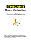
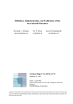
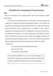
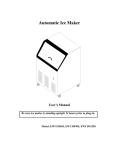
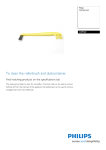
MMS Tote & Platform Lift
MMS-30
Service Manual
LIFT PRODUCTS INC
PO BOX 349
ELM GROVE WI 53122
262-521-5720 FAX 262-521-5725
Toll Free 877-543-8776
Model: MMS-30
S/N ________________________________
Customer____________________________
REGISTRATION INFORMATION
(To validate your warranty and receive updated service bulletins, please complete this form)
Date_______________
Model No.________________
How did you first hear of Lift Products?
____Magazine Ad (Specify which magazine)_____________________________________
____Recommended by a dealer (Name of Dealer)_________________________________
____Received information in the mail
____Internet
____Other (Please specify)___________________________________________________
What factors caused you to choose Lift Products?____________________________________
____________________________________________________________________________
____________________________________________________________________________
Describe how and where products are being used?____________________________________
____________________________________________________________________________
____________________________________________________________________________
Name of person completing this form______________________________________________
Title________________________________________________________________________
Company____________________________________________________________________
Street Address________________________________________________________________
City, State, Zip________________________________________________________________
Phone________________________ Fax No.________________________________________
Purchased From:
Name of Dealer_______________________________________________________________
Street Address________________________________________________________________
City, State, Zip________________________________________________________________
Phone No._____________________Fax No.________________________________________
Please fax this form to 262-521-5725.
CONTENTS
1. External Shape & Parameter Form
2. Names of Parts
3. Assembly and Debug
4. Attention and Warning
5. Operational Instructions
6. Daily Maintenance and Regular Inspection
7. Hydraulic Principle Drawing
8. Display of the Combination
9. Lists of the Parts
1
Thank you very much for using this series of platform lifts.
This operation manual has a description of the right operational methods to ensure safety and
the maintenance methods to extend the use lifetime. The operator shall read carefully and
completely understand it before using the platform lift.
This series of platform lifts are mainly used to load, lift and pile goods or take down goods from
a certain height on the flat and solid floor. It is widely used in various plants, markets and
warehouses.
1.
External Shape and Parameter Form
Technical parameters of PF series of platform lifts.
Model
MMS-30
Capacity
880 Lbs.
Lowered
8.875”
Table Height
Raised
53”
Platform Size (LxW)
25” x 22.75”
Overall Size (LxWxH) 38” x 22.5” x 57.5”
Casters
6”
Pumps to Full Lift
49
Weight
183 Lbs.
2
2.
Name of the Parts
1. Front Wheel
2. Chassis Assembly
3. Work Platform
4. Cylinder Assembly
5. Chains and Wheel
6. Slideway Handrail Assembly
7. Footstep Lever
Back Wheel
3. Installation and Debug
The parts are packed when delivered out of the factory. The user can install quickly and easily
according to the part numbers in the following order. Please have two 13, 14, or 17 spanners
and other necessary tools besides when fixing.
1. Confirm No. 11 is the platform assembly; No. 12, 13 are the handrail and cylinder assembly;
No. 14 is the chassis assembly; No. 16 is the connecting bolts (4 sets). Confirm all these are
available.
2. On the float floor, put No. 11 the platform on No. 14 the chassis according to the drawing.
3. Make No. 12 handrail go through No. 11 platforms and four rolling wheels 15, till the
position of No. 14 chassis angle iron. And also ensure the positioning hole on the bottom of the
cylinder pump plate is identical with the positioning bolt of No. 14 chassis cylinder. Connect
tightly and deadly No. 12 the handrail and No. 14 chassis with No. 16 the bolts.
4. Connect tightly the bolts of No. 13 cylinder chains and No. 11 platform connecting plates,
and use a split safe.
5. The platform lift height after being installed can be adjusted the parameter
3
6. Make sure all the parts are fixed and the bolts connected tightly and have been adjusted
well.
7. When operated without load, the platform lift raised and falls stably and normally.
8. When operated with the rated load, the platform lift rises and falls stably, the foot wheels
move flexibly and the brake works effectively.
4.
5. 9. Attention and Warning
1. The platform lift shall be used on the flat and hard floor.
2. The load shall not exceed the max. load. Transport goods strictly according to the
load curved to assure the load balance.
Operational Instructions
1. Lock the brake. And close the falling valve pole.
2. Operate the rising footstep pole to make the platform rise stably to the max. height.
Turn open the falling valve pole, and the platforms fall. Turn and close the falling
valve pole so that the platforms can stop at any height without sliding down.
3. When the load exceeds 1.2 times of the rated load, the safety valve of the cylinder
works so that the platforms cannot rise and the safety of the operation and equipment are assured.
4. When driving the platform lift load, make sure the platforms fall to the lowest position to ensure safety.
5. The falling speed of the platforms is adjustable by adjusting the angle of the positioning ring on the falling valve pole.
6. Don’t operate the rising footstep pole quickly. Otherwise, the cylinder will run empty.
7. The falling vale shall be turned open slowly with heavy load to make sure the platforms fall slowly. Otherwise, dangers will happen.
8. When the rising operation or stops at any height are done with heavy loads, the falling pole shall be closed tightly. Otherwise, the platforms will fall.
Daily Maintenance and Regular Inspection
1. Daily check if there are any deformations, looseness or abnormal noises of the connecting bolts, wheels, rolling wheels, lifting chains and wheel, the parts of hydraulic
cylinder, moving parts.
2. Daily check if there is any oil leakage of the hydraulic system.
3. Check monthly the wear and tear of the platforms, rolling wheels, chains and wheel.
4. After the lifting cylinder runs for 20 hours accumulative in the beginning. The hydraulic oil shall be charged. Afterwards the oil shall be changed once every 300 hours.
When the accumulated hours are not so much, change the oil once every 18 months.
Please fill in the specified hydraulic oil at the following temperatures listed below:
When changing the oil, adjust the pole of the pillar piston to the lowest position. The oil
shall be filled to the position of the filling hole.
4
Temperature
-5°C ~ +45°C
-15°C ~ -5°C
7. Hydraulic Principle Drawing
1.
2.
3.
4.
5.
6.
8. Hydraulic Oil
L-HM68 hydraulic oil (equivalent to ISOVG68)
L-HM46 hydraulic oil (equivalent to ISOVG46)
Out-pushing Cylinder
Turning Lifting and Falling Valve
Safety Valve
Oil Returning Valve
Work Valve
Work Cylinder
Exploded View and Part List
5
PARTS LIST FOR MMS-30
NO Name
QTY
REMARK
NO NAME
1
Slideway HandRail
1
41
Roller Chains
2
Nut
2
42
Oil-Free Bearing
3
Washer
2
43
Chains & Wheel
4
Internal Hex Bolt
2
44
Chains Cover
5
Hex Bolt
4
45
Chains Axle
6
Nut
4
46
Bolt
7
Spin
4
47
Bolt
8
Hex Bolt
4
48
Piston Pole
9
Washer
4
49
Dust-Proof Ring
10
Rolling Wheel
4
50
O-Ring
11
Oil-Free Bearing
4
51
Nylon Shield Ring
12
RB Axle
4
52
Inside Piston Sleeve
13
Fixed Platform
1
53
Pump Pole
14
Front Wheel Axle
2
54
Internal Cylinder
15
Split Shield Ring
4
55
Pump Spring Cover
16
Washer
4
56
Eccentric Sealing
17
Bearing
4
57
Oil Pump Spring
18
Front Wheel
2
58
Fixed Ear
19
Chassis Assembly
1
59
Pillar Spin
20
Lid Nut
2
60
Valve Inner
21
Internal-Teethed
2
61
O-Ring
22
Back Wheel
2
62
Valve Pole Pipe
23
Internal Hex Bolt
2
63
Outside Cylinder
24
Copper Washer
2
64
Pump Plate
25
Cone Spring
2
65
Dust-Proof Ring
26
Steel Ball
4
66
O-Ring
27
Bolt Plug
2
67
Nylon Ring
28
O-Ring
2
68
Pump Glove
29
Bolt
1
69
Oil Cup
30
Spring
1
70
Short Axle
31
Short Pin
1
71
Pump Base
32
Base Connecting
1
72
Nut
Damageable
QTY
1
1
1
1
1
1
1
1
1
2
1
1
1
1
1
1
1
2
1
1
2
1
1
1
1
2
1
1
2
1
1
1
REMARK
Damageable
Damageable
Damageable
Damageable
Damageable
6
PARTS LIST FOR MMS-30
NO Name
QTY
REMARK
NO NAME
33
Positioning Plate
1
73
Pump Pin Axle
34
Torsion Spring
1
74
Pump Ring
35
Positioning Bolt
2
75
Oil-Free Bearing
36
Positioning Ring
2
76
Steel Ball
37
Single-Direction
1
77
Axle Sleeve
38
Handle
1
78
Foot Step Lever
39
Split Pin
2
79
Rubber Glove
40
Chains Bolt
2
QTY
1
1
1
1
1
1
1
REMARK
7