1
A N T E K 9000F | U S E R ' S M A N U A L
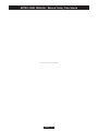
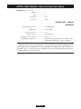
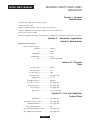
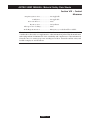
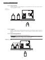
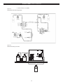
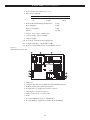
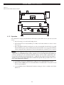
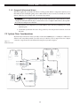
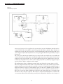
Figure 7.4
9000F Boat Inject System
Carrier gas (1) Oxygen (2) are supplied to the system at the rear panel of the Furnace Module and are
routed to the flow meter assembly (3) on the front panel of the Furnace Module. These flow meters
and their associated needle valves provide for control and monitoring of all system gas flows. The argon
carrier supplies only the Inlet Argon flow meter. Oxygen supplies the Inlet Oxygen and Pyro Oxygen
flow meters.
The carrier gases, Inlet Argon and Inlet Oxygen, are mixed at the exit of the flow meter assembly and
routed to the Carrier Loop (4) on the rear panel. From the Carrier loop, the now mixed carrier gas is
transferred to the pyrolysis tube (5) to sweep the sample into the heated combustion zone. Oxygen,
from the Pyro Oxygen flow meter, is also routed to the pyrolysis tube (5). This large supply of oxygen
provides for the complete combustion of the sample.
All combustion products, including Reagent B, exit the pyrolysis tube via a Receiving vessel (6).
There the sample is then mixed into the Receiving Solution (Reagent A). The dual headed peristaltic
pump feeds in Reagent A through the top of the Receiving Vessel and pulls the sample/Reagent A
mixture from the Receiving Vessel through the Ion Selective Electrode (ISE) Flow cell (7) and then
pumps it out to waste. The Ion Specific Sensing Electrode (8) in conjunction with its Reference
Electrode (9) senses the change in millivolt potential due to the change in fluoride concentration and
this data is collected by the computer. The software, using the Nernst Equation, calculates the
concentration of fluoride based upon the potential (mV) reading and the calibration curve being used.
41