1
VIEßMANN LON Local Operating Network Manual for Commercial, domestic and industrial boiler systems Wall-mounted gas and oil boilers Heat pumps with Vitotronic 200 control unit, Model WO1A 5719 291 GB 11/2010 Vitoligno 300-P solid fuel boiler with Vitotronic 200 control unit, Model FO1 and FW1 Oil/gas condensing boilers with Vitotronic 200 control unit, Model KW6/KW6A General Information General Information Safety Information Target Group These instructions are intended exclusively for authorized, qualified personnel. Work on gas installations must only be carried out by installers approved by the relevant gas supply company. Work on electrical equipment must only be carried out by qualified electricians. Initial start-up must be carried out by the system installer or a qualified person nominated by the installer. Regulations The following must be observed when working on this system: Statutory regulations regarding the prevention of accidents Statutory regulations regarding environmental protection Codes of practice of the relevant trade associations All relevant safety regulations as defined by authorities having local jurisdiction. Service ! Please note Service on safety-related parts can compromise the safe operation of the system. Defective components must be replaced with genuine Viessmann spare parts. Additional Components, Spare, Wear and Tear Parts ! Warning Spare, wear and tear parts that have not been tested together with the equipment can compromise its function. The installation of nonapproved components and non-authorized modifications and alterations can compromise safety and may invalidate your warranty. For replacements, only use genuine spare parts supplied or approved by Viessmann. Working on the Equipment Where gas is used as the fuel, close the main gas shut-off valve and safeguard it against unintentional reopening. Isolate the system from the power supply (e.g. at the separate fuse or a main switch) and check that it is de-energized. Safeguard the system against reconnection. Warning Electronic assemblies can be damaged by electrostatic discharge. Before beginning work, grounded objects, such as heating or water pipes, must be touched to dissipate any static charge. 5719 291 GB ! 2 VIEßMANN LON General Information Safety and Liability Danger Vitocom radio signals (in the case of communication via mobile network) may interfere particularly with pacemakers, hearing aids and defibrillators. The immediate vicinity of the operational Vitocom must be avoided if any such equipment is used. ! Warning The Vitocom only sends faults relating to connected Vitotronic control units and components connected to the Vitocom's configured inputs. For technical details, see the installation and service instructions for these devices. Requirements for fault messages: The Vitotronic control units and the Vitocom must be configured correctly. The Vitocom message paths must be established. The heating system and functionality of the messaging device must be reviewed at regular intervals. In order for signals to be transmitted in the event of power failure, we recommend the use of a UPS (uninterruptible power supply). For increased operational reliability of the heating system, we recommend the planning of supplementary measures, e.g. frost protection or monitoring for water damage. Liability Viessmann accepts no liability for loss of profit, unattained savings, or other direct or indirect consequential losses resulting from use of the Vitocom or related software, or for damage resulting from inappropriate use. The Viessmann General Terms and Conditions apply, which are included in each current Viessmann pricelist. Viessmann accepts no liability for SMS or e-mail services, which are provided by network carriers. Terms and conditions of the respective network carriers apply. 5458 766 Important Note The reproduction of common names, trade names, trademarks, etc. in this document does not imply, even in the absence of a specific statement, that such names are exempt from the relevant protective laws and regulations and therefore free for general use. LON VIEßMANN 3 General Information Product Information/ Applicability Information The information provided in this LON manual applies to the following control units: The letter (A, B, etc.) indicates the assignment/part no. of the LON module (see below). Heating circuit control units Vitotronic 050, Model HK1M Vitotronic 050, Model HK1W Vitotronic 050, Model HK1S Vitotronic 050, Model HK3W Vitotronic 050, Model HK3S Vitotronic 200-H, Model HK1M Vitotronic 200-H, Model HK1W Vitotronic 200-H, Model HK1S Vitotronic 200-H, Model HK3W Vitotronic 200-H, Model HK3S B B A B A B B A B A Boiler control units for constant / elevated boiler temperature Vitotronic 100, Model GC1 Vitotronic 100, Model GC4 Vitotronic 100, Model HC1 Vitotronic 100, Model HC1A B B C C Boiler control units for weather compensated / outdoor reset operation Vitotronic 200, Model FW1 (Vitoligno 300-P) Vitotronic 200, Model FO1 (Vitoligno 300-P) Vitotronic 200, Model GW1 Vitotronic 200, Model HO1 Vitotronic 200, Model HO1A Vitotronic 200, Model KW6 Vitotronic 200, Model KW6A Vitotronic 300, Model GW2 Vitotronic 300, Model GW4 B B B C C C C B B Cascade control units Vitotronic 300-K, Model MW1 Vitotronic 300-K, Model MW1S Vitotronic 300-K, Model MW2 Vitotronic 300-K, Model MW2S Vitotronic 333, Model MW1 Vitotronic 333, Model MW1S Vitotronic 333, Model MW2 Vitotronic 333, Model MW2S D D E D D D E D Heat pump control unit Vitotronic 200, Model WO1A (Vitocal) B E for single or cascade lag devices for cascade lead device LON module assignment A = LON module 7172 173 for boiler and heating control is factory supplied B = LON module 7172 173 for boiler and heating control is an accessory C = LON module 7179 113 for boiler and heating control is an accessory D = LON module 7172 174 for cascade control is factory supplied E = LON module 7172 174 for cascade control is an accessory 5719 291 GB If the incorrect version of the communication module is plugged into the device, the error message "BF" (incorrect communication module) appears. 4 VIEßMANN LON Contents Contents General Information................................................................................................................. 2 Safety Instructions ............................................................................................................ 2 Safety and Liability ........................................................................................................... 3 Product Information/ Applicability Information .................................................................. 4 Contents ................................................................................. Fehler! Textmarke nicht definiert. Introduction .............................................................................................................................. 6 LON technology ....................................................................................................................... 7 Fundamentals of a LON Network .................................................................................... 7 Operation of a LON Network ............................................................................................ 9 Graphical Layout of Information Structure ................. Fehler! Textmarke nicht definiert. Physical network structure ................................................................................................... 14 Topologies ...................................................................................................................... 14 Large-scale Networks ..................................................................................................... 17 Start-up of LON Network with Viessmann Controls ........................................................... 18 Start-up Procedure ......................................................................................................... 18 Overview: Functional Objects of Devices ........................................................................... 25 General Information ........................................................................................................ 25 Vitotronic 100, Models GC1, GC4 .................................................................................. 26 Vitotronic 100, Models HC1, HC1A ................................................................................ 27 Vitotronic 200, Model GW1............................................................................................. 28 Vitotronic 200, Models HO1, FO1, FW1, KW6 ............................................................... 29 Vitotronic 200, Models HO1A, KW6A and Vitotronic 300, Models GW2, GW4 ............. 31 Vitotronic 333, Models MW1, MW1S, MW2 and MW2S Vitotronic 300-K, Models MW1, MW1S, MW2 and MW2S ................................................................................................ 33 Vitotronic 050, Model HK1M, Vitotronic 200-H, Model HK1M ........................................ 35 Vitotronic 050, Models HK1W and HK1S Vitotronic 200-H, Models HK1W and HK1S . 36 Vitotronic 050, Models HK3W and HK3S Vitotronic 200-H, Models HK3W and HK3S . 37 Vitotronic 200 Model WO1A (stand-alone device) ......................................................... 39 Vitotronic 200 Model WO1A (external control) ............................................................... 41 Vitotronic 200 Model WO1A (cascade master control) .................................................. 42 Description of Functional Objects ....................................................................................... 44 General Information ........................................................................................................ 44 Node Object .................................................................................................................... 45 Heating Circuit Controller Object .................................................................................... 51 Domestic Hot Water Controller Object ........................................................................... 56 Local Flow Demand Manager Object ............................................................................. 58 CentralFflow Demand Manager Object .......................................................................... 60 Production Manager Object (cascade controller) ........................................................... 66 Boiler Controller Object .................................................................................................. 70 Information on Logical Binding ............................................................................................ 75 Information for Self-installation (Selfbinding).................................................................. 75 Device Binding with Start-up Software (Toolbinding) ..................................................... 75 Additional Information on Toolbinding ............................................................................ 82 Additional Information .......................................................................................................... 83 5458 766 Overview: Coding Addresses Affecting LON Communication ....................................... 83 Index .......................................................................... Fehler! Textmarke nicht definiert. Applicable Literature/ Websites ...................................................................................... 88 LON VIEßMANN 5 Contents Introduction This document has been prepared with various purposes in mind and for use by various target groups: The chapter "LON Technology" is directed towards heating contractors of central heating systems and other target groups, who are confronted with this technology for the first time. This chapter then, provides these target groups with a general overview of LON technology without detailed information concerning Viessmann control units and their communication. The chapter "Physical Network Structure" outlines network wiring information and is directed toward network planning specialists and heating contractors of central heating systems. This chapter provides recommendations for network development with Viessmann controls. The chapter "Start-up of LON Networks with Viessmann Controls" describes the settings to be performed on each control for communication between devices. This chapter targets heating contractors of central heating systems and systems integration specialists who initialize network communications. The chapter "Overview: Functional Objects of Devices" offers an overview of the functional objects and network variables contained in the devices. It targets network planning and system integration specialists wanting to exchange data between Viessmann controls and other devices. The chapter "Description of functional objects” is directed toward network planning and system integration specialists and describes how network variables operate, i.e. what needs to be done to create interoperable functions by means of network variables. The chapter "Information on Logical Connections" is designed for system integration specialists. It outlines the connection of Viessmann controls and allows the system integration specialist to recreate connections produced in selfbinding and in toolbinding mode. 5719 291 GB The chapter "Additional Information" features a listing of applicable publications and webpage addresses for further information on this topic. This chapter also includes a list of the coding addresses that influence LON communication between devices. 6 VIEßMANN LON LON Technology LON Technology Fundamentals of a LON Network What does "LON" mean? "LON" means "Local Operating Network Technology" and it is a network technology for the creation of automated networks. “Local Operating” refers to the fact that network participants are governed by their own "intelligence" and can therefore make their own, independent, local decisions without relying on assistance from the central network node. Network participants - referred to as nodes in the LONWORKS Technology structure - can be control units, sensors, computers and communication devices, etc. Transmitted data consists of measured values, metered values, messages and activation or deactivation signals. Who is who? The LONWORKS Technology originated at the U.S.-based Echelon Corporation that was founded in 1986. The U.S.-based "LonMark Interoperability Association” is an independent association of manufacturers, end-users and system integration specialists comprising more than 100 companies worldwide. It sets technical guidelines, promotes and fosters the LONMARK interoperability standard worldwide and awards the LONMARK prize for interoperable products. Viessmann is a member of this organization. In Germany, the independent "LonMark Deutschland e.V" serves as an association of manufacturers, end customers and system integrators from German-speaking countries. It was established in 1995 and sees itself as an information hub and representation of German interests in the market and in standardisation bodies. Viessmann is also a member of this association. LONWORKS Components LONWORKS technology encompasses all components required for the development, start-up and operation of automated networks: hardware, software and the know-how. The neuron chip is an electric circuit developed specifically for the LONWORKS Technology by Toshiba and Cypress, and constitutes principal hardware component of the LON technology. The chip is physically located on the network node – in Viessmann networks on the communication module – and allows data exchange between individual control units. 5458 766 Transceivers are used for interfacing with the transfer medium. The transfer medium can be anything from a twisted pair wires to a radio transceiver. A transceiver is a component that acts both as a data transmitter and a data receiver. The transceiver provides the physical connection to the network and ensures that network nodes from different manufacturers comply with the physical requirements for communication on the respective transfer medium. The network node receives its "intelligence" from the software contained on the neuron chip. This software is both the application program, which safeguards the functionality of the node as part of the application process, as well as the operating system, which provides the communication functions. When communicating, the LonTalk Protocol is used. The LonTalk Protocol is a communication protocol stored permanently on the neuron chip. This protocol ensures that the structure of the message exchange between network nodes adheres to strict rules. Similar to the worldwide telephone system, strict requirements were put in place within the LON Technology to ensure that data exchange between devices of difference manufacturers can take place. LON VIEßMANN 7 LON Technology 5719 291 GB Another significant component for the creation of interoperable network nodes is the know-how. Options contained in the LONWORKS concept, such as the implementation of Standard Network Variable Types (SNVTs), support the development of network nodes that can communicate with foreign network nodes without prior consultation. 8 VIEßMANN LON LON Technology Operation of the LON Network Network Variable Concept A network node communicates with other nodes in the network using so-called network variables (NVs). The function of network variables can be illustrated with the following analogy: in an electrical installation, terminal A of a switch is connected to terminal B of a lamp to turn the lamp on and off. Elektroinstallation Electrical Installation Switch Schalter Lamp Lampe Cable Leitung L A B N Network Variables Communication Netzvariablen-Kommunikation Lamp Switch Schalter Lampe Switch on! Schalte! Transfer Übertragungsmedium medium Light on? Licht ein? When communication with network variables, the application program in the node "switch" interprets the signal from the electrical contact and writes it, in case of change, to the output network variable “switch on!” Then the neuron ensures that the network variable is released to the transfer medium (network). When the information arrives at the node "lamp", the information is interpreted by the application program and the lamp is switched on. 5458 766 Now the neuron of the switch requires information regarding which node is designated to receive the sent data. The receiving node "lamp" also requires information regarding which data and from which sender it is to receive with the input network variable “light on”. This information is generated at the so-called binding process. Binding also determines which output network variable (see terminals in the electrical installation, which switch controls which lamp) of a sender is to be connected with which input network variable from which receiver (see wiring of a cable in electrical installation). LON VIEßMANN 9 LON Technology Logical Connections In the LON Network, devices are physically connected to each other via the respective transfer media. For example, all devices are connected with a twisted pair of wires and are equipped with a matching transceiver. This physical connection alone, however, is not sufficient for data exchange and cooperation of the connected devices. Because physically all devices are connected to “the same wire", and all devices have access to all information through input network variables (see terminal in electrical installation example), each device must be informed as to which information is addressed to it. Such settings – which data must be sent to which receiver or which data must be received by which sender – are referred to as logical connections. Such logical connections are generated in the so-called binding process. This can take place with the help of a computer (e.g. notebook PC), that is connected to the network and a software package - LONWORKS start-up software (binding tool). Should a system contain only Viessmann control units, which are set up for communication as recommended by Viessmann, the connection (binding) takes place in a different manner: Viessmann controls are equipped with a built-in start-up program, which generates the logical connections required by Viessmann controls for joint operation. This requires only a few configuration adjustments. This procedure is referred to as selfbinding. Addressing and Logical Network Structuring Aside from its physical structure, any large network also requires a logical structure. The purpose of a network is to facilitate the exchange of data between various network participants. In order for a LON node to address another node or even a completely different group of nodes, each node within the network requires a unique address. This can be explained by a comparison with the telephone network. Each network participant in the telephone network has his/ her own worldwide unique participant address, consisting of the country code, area code and participant's number. Similarly, each LON node in a LON network is designated a unique logical address. This takes place when binding each node into the network, either with the binding tool or, in the case of Viessmann control units, by manually configuring a system address and a participant number during start-up. The logical address of a LON node is divided into three hierarchical parts: Domain ID, Subnet ID and Node-ID. LON network English Number range Domain ID 1 ... 248 Subnet ID 1 K 255 Node ID 1 K 127 Controls via selfbinding derived from: Always fixed System number Participant number Comparison: Telephone network Country code Area code Participant number If a node wants to send a message to another node (for example, because the value of a connected network variable has changed), it will use the logical address as the receiver address (e.g. Domain: 001, Subnet: 15, Node: 27). 5719 291 GB In addition to this logical address, each neuron chip has a physical address, designated by a unique 48-bit serial number, called the Neuron ID. This is not normally used when exchanging data messages between nodes; instead the logical address is used. The neuron ID is used for the initial introduction of a node to a network as well as for network management and diagnostic functions. 10 VIEßMANN LON LON Technology Logical Address Structure offers the following advantages: • Defective nodes are easier to replace. • Data messages are shorter than when the neuron ID is used. • In large-scale networks, the BUS load can be reduced by using routers. With routers, networks can be divided into separate subnets. Routers ensure that only those messages intended for participants of a specific subnet pass into that subnet. This way, the BUS load of respective subnets is reduced accordingly. Group Address Structure Aside from structuring a network into domains and subnets, nodes can also be assigned to logical groups. This becomes particularly practical if multiple participants are to receive the same message. This way, for example, a main disconnect button can send the shut-off message in one single message to all participants in the "lamps" group. Without this group definition, the message would have to be sent to each lamp individually. The following limits apply to the group address structure: up to 256 groups may be defined within a domain. Each node can participate in up to 15 groups. Viessmann control units also use the group addressing during selfbinding. Accordingly, all devices containing a heating circuit controller belong to a group called “load”. These now behave in accordance with certain messages regarding heat production. Transfer Media The neuron chip is designed for connection to various transfer media. Transmission via a twisted pair of wires at different transmission speeds with and without superimposed direct current for power supply to smaller network nodes is most often used. Alternately, information exchange can take place using existing power lines. Fibre optics and wireless transmission are other available transfer media. Various transfer media may also be used within one system. In order to copy data from one medium to another, routers are used. Viessmann controls can be equipped with communication modules for the twisted pair of wires. Communication Properties In a LONWORKS network, all devices have equal rights. There is no BUS master permitting transmission. The design of the neuron chips ensures that message collision is prevented. Nevertheless, collisions can never be completely avoided, especially in networks with a high communication rate. 5458 766 Various mechanisms ensure that, depending on the importance of the messages, these arrive at their intended recipients. Data transmitted without a return receipt (unacknowledged) is relatively unreliable, since lost messages are not repeated. For important data, repeated message sending, message receipt (acknowledgement) or a request-response procedure can verify a safe transmission. These connection properties can be selected during start-up for each individual connection, using the binding tool. LON VIEßMANN 11 LON Technology Graphical Layout of Information Structure In order to illustrate the complex functional structure of a LONWORKS node in a structured and clear manner, an illustration of each function segment is required: The node – i.e. the device and its functions as a whole – is first divided into its functional components. For example, one functional component could be a heating circuit control. This functional component comprises all the input and output configuration variables for the applicable heating circuit control. Instead of "functional component", the term "functional object" or "object" is used. One node can therefore have more than one functional object. 12 VIEßMANN 5719 291 GB In addition to the application functions of a device, a node may contain a node object, in which all network variables are stored that are applicable to the node as a whole and not to a single application function. LON LON Technology The following illustration is used for exact representation of an object (functional object) within a node. 5458 766 The object itself is illustrated by a rounded rectangle; a description may be inserted into the upper segment. Input variables are represented by arrows on the left whose names start with the letters "nvi". Output variables are shown as arrows on the right, their names start with the letters "nvo". LON VIEßMANN 13 Physical Network Structuring Physical Network Structuring For each transfer medium - more precisely, for each transceiver type – certain rules apply, which must be followed to ensure uninterrupted communication between all participating BUS devices. These rules apply to: • Wiring structure (topology) of the LON devices • Maximum wire lengths • Maximum permissible number of devices • Layout of the BUS end Viessmann communication modules contain the transceiver type FTT 10-A. The rules applicable to this transceiver type are specified below. For further information regarding specific wiring requirements, visit www.echelon.com. More information can also be found in the LonWorks Installation Handbook (2nd edition) (ISBN 3-8007-2687-4). Maximum Number of Nodes A maximum of 64 nodes are permissible for transceiver type FTT 10-A in one network segment. For large-scale networks, a division into network segments is required (see chapter entitled "Large-Scale Networks"). Safety Instructions When connecting devices or installing wires, take note that in all instances the requirements of low and extra voltage circuits, i.e. 0.3 inches/ 8 mm air distance and access clearance to live components are observed. In case of field-supplied and installed components, an “electrically safe separation” must be ensured. Topologies BUS or Line Topologies Networks with an FTT 10-A receiver can be composed of different topologies. However, Viessmann recommends the use, where possible, of line or BUS structures for the following reasons: As opposed to free topology, this unique form of network topology allows for a significant increase of the maximum permissible wire length. Within this structure, the maximum cable length for FTT 10-A networks is reached. • Viessmann communication modules, with two RJ45 plug-in connectors each and ready-made connecting cables (Viessmann part no. 7143 495), allow for easy installation. • When using line structuring, not like ring topology, wiring is reverse polarity-protected. This means the BUS wires can be reversed. • Viessmann end of line resistors (Viessmann part no. 7143497) are designed specifically for this BUS structure. 5719 291 GB • 14 VIEßMANN LON Physical Network Structuring BUS or Line Topology Network node Terminator resistor Networks with BUS or line structuring structuring using Viessmann components can be set up as follows: a) Mit Systemleitung With system wiring Heating HeizkreisCircuit Conrol regelung Heating HeizkreisCircuit Conrol regelung Control Regelung 1 7mft. 7m/ 23 Terminator resistor 1 Abschlußwiderstand 7143 497 (2 pcs) 7143 497 (2 Stück) 1 7m ft. 7m/ 23 2 2 2 7142 495 b) Mit Systemleitung und Kupplung With system wiring and couplingzur forVerlängerung extension Heating HeizkreisCircuit Conrol regelung Control Regelung 1 7m 7m/ 23 ft. 2 7mft. 7m/ 23 3 Heating HeizkreisCircuit Conrol regelung 7m/ 7m23 ft. 2 2 3 2 3 3 LONLONKupplung coupling 7143 7143496 496 4 Anschlußdose (bauseits)connect Field connections, Adern 1 und 2 sowie Schirm shield and wires 1 and 2 anschließen 1 7m23 ft. 7m/ x mal 7m23 ft. x times 7m/ LONVerbindungsleitung LON connecting cable 7143 495 5 Field-supplied Datenleitung (bauseits) data wiring c) Mit bauseitiger Anschlu Anschluss ssdose dose und With field-supplied connection boxVerlängerung and extension 1 Heating HeizkreisCircuit Conrol regelung Heating Heizkreisregelung Circuit Conrol Control Regelung 2 1 4 4 4 7m/ 23 7mft 7m23 ft. 7m/ 2 1 2 2 4 7m/ 7m 23 ft. 2 5 7m23 ft. 7m/ 1 2 1 2 1 2 5 For networks with BUS or line topologies, a terminator resistor (Viessmann Part Part No. 7243 497, package of two) must be installed at both ends of the network segments, in order to buffer reflections of data signals at the cable ends. This terminator resistor is not only a standard resistor, but rather a specific RC circuit. It is equipped with an RJ45 plug-in connector and can be plugged in at the communication module. For networks with FTT 10-A transceivers, the following maximum values are possible for BUS and line topologies: Recommended cable types TIA 568 Category 5 (Cat. 5) cable JY(ST)Y 2x2x0.8 mm (phone cable) Total maximum cable length 2950 ft/ 900 m 2460 ft/ 750 m 5458 766 For transition to field-supplied wiring, the LON Connection Terminal (Viessmann part no. 7171 784) can be used. For communication, wires1 and 2, as well as shielding are always required. LON VIEßMANN 15 Physical Network Structuring Free Topology Free topology allows the installation of any networks, regardless of structure, in buildings buildings.. As the name FTT (Free Topology Transceiver) suggests, the BUS line can be installed with any number of branches when transceiver type FTT 10-A is used. Star-shaped, ring-shaped and line structures are all possible, as well as any combination combination of the three. Free Topology Ring Topology Star Topology Combination Topology K = Network node A = Terminator resistor For networks with free topology, a network segment with a special terminator (52.3Ω, not supplied by Viessmann – e.g. available from Echelon) must be connected in order to dampen reflections of data signals at the cable ends. For networks with FTT 10-A and free topology, the following maximum values are possible: Recommended cable type TIA 568 Category 5 (Cat. 5) cable JY(ST)Y 2x2x0.8 mm (phone cable) Max. distance between nodes 823 ft/ 250 m 1049 ft/ 320 m Max. cable length 1476 ft/ 450 m 1640 ft/ 500 m 5719 291 GB The maximum distances between nodes as specified in the table refer to the maximum distances between any two nodes - not only to the maximum distance between neighbouring nodes! The specified maximum distances also apply to distances between each node and the BUS termination; i.e., depending on the type of cable, no node may be installed more than 823 or 1049 ft or 250 or 320 m cable length away from the terminator resistor. 16 VIEßMANN LON Physical Network Structuring Large-scale Networks Large-scale networks must be divided into several network segments in order to function properly. With each additional network segment, another 64 nodes can be installed. Maximum cable lengths are applicable to one segment only. For the connection of network segments, routers and repeaters are used: Repeaters are devices with two BUS connections, reinforcing signal strength. Since repeaters only amplify the messages (rather than reproducing them), a maximum of two repeaters may be connected in a logical series. After that, a router is required for message reproduction. Routers – like repeaters – are devices with two BUS connectors. Their application range, however, exceeds that of repeaters. Routers are equipped with a message filter function and can therefore decide which messages to forward to the other BUS side. This function allows the reduction of the communication load (= number of messages per time unit) within individual network segments. The decision whether or not to forward a message is made by the router by evaluating the logical destination address in the message header. The router is therefore seen as a device which performs logical network structuring, rather than physical network structuring. 5458 766 Another difference between repeaters and routers is the fact that routers can be equipped with two different transceivers. This allows different transfer media to be connected to each other. This way, for example, an extension to a building may be built using a twisted pair of wires, while in the existing building Power Line Technology (information transfer via 120/ 240V line voltage) was used. LON VIEßMANN 17 Start-up of a LON Network with Viessmann Controls Start-up of a LON Network with Viessmann Controls Start-up Procedure In this chapter we will discuss the required steps for the start-up of a LONWORKS Network with Viessmann controls. (For the Vitotronic 200, Model WO1A heat pump control, see service manual) 1. Installation and Connection All controls must be installed and connected according to the accompanying Installation Instructions. The communication module must be connected according to the applicable Installation Instructions. 2. Network Installation The communication modules of the control units must be connected via BUS cables or field-connected (for longer cable lengths). All terminator resistors must be connected as described in the chapter "Physical Network Structure". 3. Network Configuration When activating control units, they connect into one system automatically using the integrated self-installation mechanisms to form a system. For complete start-up of communication functions, the following steps are required (depending on system type): 3a. Systems without Data Exchange with Devices from Other Manufacturers For systems with Viessmann control units without data exchange with devices from other manufacturers, the following configuration parameter (coding address) adjustments are required (factory settings are printed in bold): on boiler control units for constant / elevated temperature operation: CA Description: Function (hex) 01 Single/ Multiple boiler system: determines whether it is dealing with a single or multiple boiler system 07 Boiler number: determines the number of a boiler in a multiple boiler system 77 Participant number: determines node address via selfbinding 98 System number: determines the subnet number via selfbinding 79 System fault manager: determines whether the device should record all fault messages from the heating system, check participants for failure and generate a complied fault message Value 1 2 1 ... 4 Adjustment necessary? Only for multiple boiler systems: Single boiler system Multiple boiler system Only for multiple boiler systems: Boiler number 1 ... 4 Only if the participant number "1" has already been assigned to another participant: 1 ... 99 Participant number 1 ... 99 Only if several independent heating systems are present in one network: 1 ... 5 System number 1 ... 5 Only if device is to check other devices for fault/ failure (Please note: only one control unit per heating system can be the fault manager!): Device is not fault manager 0 1 Device is fault manager (Vitotronic 100 HC1 and HC1A cannot be fault managers) 5719 291 GB CA = Coding Address 18 VIEßMANN LON Start-up of a LON Network with Viessmann Controls on boiler control units for weather compensated / outdoor reset operation: CA Description: Function (hex) 77 Participant number: determines the node address via selfbinding 98 System number: determines subnet address via selfbinding 79 System fault manager: determines whether device should record all fault messages of the heating system, check participants for failure and generate a compiled fault message Sending time information: allows the device to send the time to all other nodes in a domain 7B Value Only if participant number "1" has already been assigned to another participant: 1 ... 99 Participant number 1 ... 99 Only if several independent heating systems are present in one network: 1 ... 5 System number 1 ... 5 Only if device is NOT to check other devices for fault/ failure (Please note: only one control unit per heating system can be the fault manager!): 0 Device is not the fault manager Device is the fault manager 1 0 1 81 Receiving time information from LON: allows the setting of a node clock according to time information provided by the network 0 1 2 3 97 Sending/ Receiving outdoor temperature: allows the sending and receiving of the outdoor temperature within a subnet (please note: only one participant within a system must send the outdoor temperature) CA = Coding Address Adjustment necessary? 0 1 2 Only if device is NOT to send its time to the network (Please note: only one device per network must provide time information!): Device does not send time Device proves time information Only if device is to use the time provided by network to set its real time clock: Internal clock without daylight saving time Internal clock with daylight saving time Radio clock Device takes time from network Only if the device is to send the measured outdoor temperature to other devices or is to adopt the network outdoor temperature: Use local outdoor temperature Adopt outdoor temperature from LON Use outdoor temperature from outdoor sensor and send to LON on cascade control units: CA Description: Function (hex) 35 Number of boilers: determines number of boilers in a system 77 Participant number: specifies the node address via selfbinding 98 System number: determines the subnet address via selfbinding 79 System fault manager: determines whether device is to record all fault messages of the heating system, check participants for failure and generate a compiled fault message Send Time Information: allows the device to send the time to all other nodes in the domain 7B Value Adjustment necessary? Only if it is not a four-boiler system: Number of boilers 1 ... 4 Only if participant number "5" has already been assigned to another participant: 1 ... 99 Participant number 1 ... 99 Participant number 5, factory default setting 5 Only if several independent heating systems are present in one network: 1 ... 5 System number 1 ... 5 Only if the device is NOT to check other devices for fault/ failure (Please note: only one control unit per heating system can be the fault manager!): 0 Device is not the fault manager Device is the fault manager 1 1 ... 4 5458 766 0 1 Only if the device is NOT to send its time to the network (Please note: only one device per network must provide time information!): Device does not send time information Device provides time information LON VIEßMANN 19 Start-up of a LON Network with Viessmann Controls CA Description: Function (hex) 81 Receiving Time Information from LON: allows the setting of a node clock according to time information provided by the network Value 0 1 2 3 97 Sending/ Receiving Outdoor Temperature: allows the sending and receiving of the outdoor temperature within a subnet (Please note: only one participant within a system must send the outdoor temperature!) CA = Coding Address 0 1 2 Adjustment necessary? Only if the device is to use the time provided by the network to set its real time clock: Internal clock without daylight saving time Internal clock with daylight saving time Radio clock Device takes time from network Only if the device is to send the measured outdoor temperature to other devices or is to adopt the network outdoor temperature: Use local outdoor temperature Adopt outdoor temperature from LON Use outdoor temperature from outdoor sensor and send to LON on a Vitotronic 200, Model WO1A heat pump control, see "Vitotronic 200, Model WO1A Service Instructions". on a Vitotronic 300-K/ 333 MW2 and 300-K/333 MW2S, the following additional setting is required: CA Description: Function (hex) 89 Boiler connection: determines the communication BUS for boiler connection Value 1 0 Adjustment necessary? Whenever the LON communication BUS is used: Boilers connected via LON Boilers connected via KM BUS Note: If the coding address is not visible, coding address 8A must first be set to 176. Then coding address 89 is switched to visible. Afterwards, coding address 8A can be reset to 175. 5719 291 GB CA = Coding Address 20 VIEßMANN LON Start-up of a LON Network with Viessmann Controls on heating circuit controllers: CA Description: Function (hex) 77 Participant number: determines the node address via selfbinding 98 System number: determines subnet address via selfbinding 79 System fault manager (not available with Vitotronic 050HK1M): determines whether device is to record all fault messages of the heating system, check participants for failure and generate a compiled fault message Sending Time Information: allows the device to send the time to all other nodes in a domain 7B Value Only if the participant number "10" has already been assigned to another participant: 1 ... 99 Participant number 1 ... 99 Participant number 10, factory setting 10 Only if several independent heating systems are present in one network: 1 ... 5 System number 1 ... 5 Only if the device is to check other devices for fault/ failure (Please note: only one control unit per heating system can be the fault manager!): Device is not the fault manager 0 1 Device is the fault manager 0 1 81 Sending/ Receiving of Outdoor Temperature: allows the sending and receiving of the outdoor within a subnet (Please note: only one participant within a system may send the outdoor temperature!) 0 1 2 3 0 1 2 Only if the device is to send its time to the network (Please note: only one device per network must provide time information!): Device does not transmit the time Device transmits the time Only if the device is to use the time provided by the network to set its real time clock: Internal clock without daylight saving time Internal clock with daylight saving time Radio clock Devices take time from network Only if the device is to send the measured outdoor temperature to other devices or is to adopt the network outdoor temperature: Use local outdoor temperature Adopt outdoor temperature from LON Use outdoor temperature from outdoor sensor and send to LON 5458 766 97 Receiving Time Information from LON: allows the setting of a node clock according to the time information provided by the network Adjustment necessary? LON VIEßMANN 21 Start-up of a LON Network with Viessmann Controls 3b. System with Data Exchange with Devices from Other Manufacturers Note Please observe the coding specified in section 3a. For systems with data exchange with other devices from other manufacturers, or for systems with Viessmann controls located on opposite sides of a router that must correspond with each other, start-up software (binding tool) is required for the logical connection of these devices. The toolbinding process should be performed by the system integrator. The system integrator has the task of logically combining the various devices in the system to one main function. In chapter “Connecting Devices via Start-up Software (Toolbinding)” all logical connections required for the harmonization of Viessmann devices are described. During toolbinding, all necessary information for connecting the devices is produced with the help of a computer and the LONWORKS Binding Tool software (connected to the network) and is written to the nodes. The process is as follows: • • • • • All devices in the network are identified and introduced to the tool. Objects used by these devices are identified and named. On the monitor, the user connects all output variables to the input variables of the objects. Depending on which tool is used, this takes place in a graphical or text format. Everything else is usually done by the application program. The tool sends a series of network management messages via BUS to the nodes, reconfiguring them. The toolbinding option also requires the adjustment of the configuration parameter (coding addresses) as described in 3a. This is the only way to ensure the desired function. From this point on, the node will automatically send changes to its output variables to all predetermined recipients, while its input variables will receive all the data from the BUS addressed to it. 4. Participant Check Once the binding process is completed and the parameters have been set, a participant check must be performed. This participant check shows if all Viessmann control units are communicating with each other. Before doing this, update the participant list of the fault manager (press the D button during the participant check to erase the list, and wait for ca. 2 minutes until the list reappears). 5719 291 GB The procedure is dependent on the respective control unit model. A description for the execution of the participant check must be taken from the respective service documentation. 22 VIEßMANN LON Start-up of a LON Network with Viessmann Controls Example: Performing a Participant Check Communication with the system devices connected to the fault manager is tested by means of a participant check. Communication of control units connected to the fault manager is checked with the Participant Check. Prerequisite: Control must be programmed as fault manager (coding "79:1“) The LON Participant Number has to e programmed in all controls Participant list in fault manager has to be current Participant Check 1. Press and for 2 seconds. simultaneously Participant Check Participant Number Serial List Number 2. Select desired Participant with + or . 3. Activate Check with . Display will indicate "Check OK“ if communication between both control units is established. If no communication is the case, "Check not OK“ is displayed. 4. To check other participants refer to points 2 and 3. Participant Check is finished. 5458 766 5. Press and simultaneously for 2 seconds. "Check“ is flashing in display until Participant Check is finished. Display and all LEDs are flashing for 60 seconds on dialed-up participant. Check for LON connections and fault messages on respective control unit. LON VIEßMANN 23 Start-up of a LON Network with Viessmann Controls Example: Performing a participant check with the Vitotronic 200, Model WO1A (black programming unit) Communication of control units connected to the fault manager is checked with the Participant Check. Prerequisite: Control must be programmed as fault manager (set parameter 7779 "LON fault manager" to 1) The LON Participant Number has to be programmed in all controls Participant list in fault manager has to be current Performing the participant check: 1. Press OK and å simultaneously for approx. 4 seconds. 2. "Service functions" 3. "Participant Check" 4. Select desired participant (e.g. participant 10). The participant check for the selected participant is initiated. Successfully tested participants are designated as "OK". Unsuccessfully tested participants are designated as "Not OK". Note If the participant check is carried out by another control unit, the participant number and "Wink" appear on the display for approx. 1 min. Note To carry out another participant check, create a new participant list with menu item "Delete list?” 5. Configuration for the Heating System 5719 291 GB Following the participant check, a configuration for the heating system (adjustment of hydraulic layout, burner etc.) of the system can be performed. For more detailed information, please refer to the Installation and Service Instructions of Viessmann controls as well as those of other system components. 24 VIEßMANN LON Overview: Functional Objects of Devices Overview: Functional Objects of Devices General Information 5458 766 Communication modules provide the required functional objects and network variables required by all devices. Depending on the device and its configuration, network variables and/or entire objects may not be functional. LON VIEßMANN 25 Overview: Functional Objects of Devices 5719 291 GB Vitotronic 100, Models GC1, GC4 26 VIEßMANN LON Overview: Functional Objects of Devices 5458 766 Vitotronic 100, Models HC1, HC1A LON VIEßMANN 27 Overview: Functional Objects of Devices 5719 291 GB Vitotronic 200, Model GW1 28 VIEßMANN LON Overview: Functional Objects of Devices 5458 766 Vitotronic 200, Models HO1, FO1, FW1, KW6 (Continued on following page) LON VIEßMANN 29 Overview: Functional Objects of Devices Continued: Vitotronic 200, Model HO1 K 5719 291 GB Note For the Vitotronic 200, Models FO1 and FW1, heating circuit 1 is also controlled (mixer M1). 30 VIEßMANN LON Overview: Functional Objects of Devices 5458 766 Vitotronic 200, Models HO1A, KW6A and Vitotronic 300, Models GW2, GW4 (Continued on following page) LON VIEßMANN 31 Overview: Functional Objects of Devices 5719 291 GB Continued: Vitotronic 200, HO1A, KW6A and Vitotronic 300, GW2, GW4 32 VIEßMANN LON Overview: Functional Objects of Devices 5458 766 Vitotronic 333, Models MW1, MW1S, MW2 and MW2S Vitotronic 300-K, Models MW1, MW1S, MW2 and MW2S (Continued on following page) LON VIEßMANN 33 Overview: Functional Objects of Devices In the case of the Vitotronic 333, 300-K Model MW2, the PM objects only function when communication with the boiler control units takes place via the LON module (coding address "89:1") – otherwise, communication with the boiler control units takes place via the KM BUS. 34 VIEßMANN LON 5719 291 GB Continued: Vitotronic 333, Models MW1, MW1S, MW2 and MW2S, Vitotronic 300-K, Models MW1, MW1S, MW2 and MW2S Overview: Functional Objects of Devices 5458 766 Vitotronic 050, Model HK1M, Vitotronic 200-H, Model HK1M LON VIEßMANN 35 Overview: Functional Objects of Devices 5719 291 GB Vitotronic 050, Models HK1W and HK1S Vitotronic 200-H, Models HK1W and HK1S 36 VIEßMANN LON Overview: Functional Objects of Devices 5458 766 Vitotronic 050, Models HK3W and HK3S Vitotronic 200-H, Models HK3W and HK3S (Continued on following page) LON VIEßMANN 37 Overview: Functional Objects of Devices 5719 291 GB Continued: Vitotronic 050, Models HK3W and HK3S, Vitotronic 200-H, Models HK3W and HK3S 38 VIEßMANN LON Overview: Functional Objects of Devices 5458 766 Vitotronic 200 Model WO1A (stand-alone device) (Continued on following page) LON VIEßMANN 39 Overview: Functional Objects of Devices Continued: Vitotronic 200, Model WO1A (stand-alone device) 5719 291 GB Please note: Depending on system configuration, one or more of the function objects and/or network variables may not function. 40 VIEßMANN LON Overview: Functional Objects of Devices 5458 766 Vitotronic 200 Model WO1A (external control) LON VIEßMANN 41 Overview: Functional Objects of Devices (Continued on following page) 42 VIEßMANN LON 5719 291 GB Vitotronic 200 Model WO1A (cascade master) Overview: Functional Objects of Devices 5458 766 Continued: Vitotronic 200, Model WO1A (cascade master) Please note; Depending on system configuration, one or more of the function objects and/or network variables may not function. LON VIEßMANN 43 Description of Functional Objects Description of Functional Objects General Information The description of the function objects of Viessmann control units explains in detail the meaning and function of each individual network variable. First, it must be determined whether a network variable is event-oriented or transmitted cyclically. In the tables for the input network variables (nvi K), the column “RcvHrtBeat” indicates whether a cyclical reception of these network variables is expected. If “Yes” appears in this column, it is expected that the network variable is received cyclically. If no message was received during the “Receive-Heart-Beat-Time” for this network variable, the default value is used internally until another message is received. The “Receive-Heart-Beat-Time” is adjustable (in minutes) with coding address “9C” on the control unit. The factory default setting is set to 20 minutes. The “Receive-Heart-Beat-Time” should always constitute a multiple of the “SendHeartBeat-Time”. If “No” appears in the column “RcvHrtBeat”, the network variable is received sporadically. In the tables for the output network variables (nvo K), the column “SendHrtBeat” indicates whether the network variable is sent cyclically. If “Yes” appears in this column, the network variable is sent cyclically. Cyclical sending takes place with the “SendHeartBeat-Time”. The “SendHeartBeat-Time” is adjustable via a binding tool as a configuration parameter “nciSndHrtBt” (in seconds). The factory default setting is set to 60 seconds. If the “SendHeartBeat-Time” is drastically increased, the “Receive-Heart-Beat-Time” is to be adjusted accordingly (see above). If “No” appears in the column “SndHrtBeat”, this network variable is only transmitted sporadically, e.g. when changing the value by a certain amount. The column "SNVT Type" determines which data type or data format is used. Data types starting with "SNVT ... " are Standard Network Variable Types, i.e. data types defined as standard data formats by LONMARK. Data types starting with "UNVT ... " are User-Defined Network Variable Types, i.e. Viessmann-defined data formats. Since heat pump behaviour (Vitocal devices) differs greatly from that of pure heat generators due to their advanced features (optional cooling function), these are, in part, described separately in connection with the general object description. 5719 291 GB Note: 44 VIEßMANN LON Description of Functional Objects Node Object LonMark requires a node object for each node. It contains variables that are applicable to the device in general and not only to one single functional object. At the very least, network variables listed as "Mandatory Network Variables" must be available. Viessmann controls (for exceptions see chapter "Overview: Functional Objects of Devices") generally provide the above illustrated network variables. Configuration Parameter (configuration properties) of the node object: Name SNVT type nciNetConfig SNVT_config_src nciSndHrtBt SNVT_time_sec Description Tool/ selfbinding: see "LonMark Application Layer Interoperability Guidelines", version 3.2, chapter 3 (determines if selfbinding or toolbinding occurs), 0 = CFG_LOCAL (factory default setting, self-installed) 1 = CFG_EXTERNAL (tool-installed) SendHeartBeat, send repeat rate: time for cyclical transmission of network variables in segments of 100 milliseconds, factory default setting = 60.0 sec RcvHrt Beat No No Both of these configuration parameters can be changed with a binding tool. "nciNetConfig" determines if a node is bound by tool or selfbinding. The factory setting is "CFG_LOCAL" (selfbinding). 5458 766 With “nciSndHrtBt” the “SendHeartBeat-Time” is set. It determines how often cyclical transmission of network variables takes place. This time should only be changed if absolutely necessary, for example when the communication load must be reduced. It should be verified, if the Receive-Heart-Beat-Time (configuration parameter 9C) requires adjustment. LON VIEßMANN 45 Description of Functional Objects Input network variables of the node object: Name SNVT Type nviNode Request nviNode TimeSet SNVT_obj_request Object request, see "LONMARK Application Layer Interoperability Guidelines", version 3.2, chapter 3 SNVT_time_stamp Time of day input: with this network variable the internal actual clock time of the device can be set. For Vitotronic 100, Model GC1, it is always activated; for all other control devices only if coding address "81:3" is selected. It is recommended to designate one device in the network as the time of day sender and the other devices as the time recipients. This ensures that the clocks of all devices in the network are synchronized. SNVT_alarm Fault message input: this input variable receives fault messages from all other Viessmann devices in the system. This function is used by the central fault manager to receive cyclical fault messages from the participants. Fault messages are transmitted cyclically, using SendHeartBeat. This variable is only functional if coding address "79:1" is selected. (For Vitotronic 200, Model WO1A, parameter 7779 "LON fault manager" set to 1.) (This variable is not available for Vitotronic 050, Model HK1M and Vitotronic 100, Model HC1.) SNVT_temp_p Outdoor ambient temperature, outdoor temperature input: instead of using the temperature measured by the outdoor temperature sensor installed directly on the device, the outdoor temperature measured by another device may be used. The outdoor temperature, received via nviNodeOATemp is only functional if coding address "97:1" has been selected. If no temperature value is received during the Receive-Heart-Beat-Time, a default value of 32°F/ 0°C is used. nviNode Alarm nviNode OATemp Description RcvHrt Beat No No No Yes Output, network variables of the node object: Name SNVT Type nvoNode Status nvoNode Alarm SNVT_obj_ status Object status: see "LonMark Application Layer Interoperability Guidelines", version 3.2, chapter 3 SNVT_alarm Output for fault messages: the last error message is transmitted cyclically. If there is no fault, the fault code "00" is transmitted. A message is generated for every participant failure. (For content of data structure and meaning of fault code see below.) SNVT_time_stamp Time of day output: output variable of the time synchronization of other devices (only applicable for devices with their own system clock). This network variable is only activated if coding address "7B:1" is selected. SNVT_ temp_p Outdoor temperature output: sends the actual outdoor temperature to be used in other devices (only for devices equipped with an outdoor temperature sensor input). This network variable is only activated if coding address "97:2" is selected. SNVT_state Relay status output: logical status of the device's control signals: structure in which logical signals of the control unit are being exported. If the corresponding signals are available for each control unit (see below), the following applies: 1=on, 0=off or not available. nvoNode TimeSet nvoNode OATemp SndHrt Beat No Yes Yes Yes Yes 5719 291 GB nvoNode RlyState Description 46 VIEßMANN LON Description of Functional Objects Logical signals of control units in nvoNodeRlyState: Vitotronic Bit 0 1 2 3 4 5 6 7 8 9 10 11 12 13 14 15 Logical signal DHW loading pump Recirculation pump Heating circuit pump 1 Heating circuit pump 2 Heating circuit pump 3 Setback contact HKP 1 Setback contact HKP 2 Setback contact HKP 3 Supply pump Primary pump heat exchanger set for DHW tank loading Pump for loading system Boiler circuit or common supply pump Internal pump Shunt pump Diverting valve in space heating position Flue gas heat exchanger pump ThermControl switching contact Diverting valve in DHW position Burner stage 1 Burner fault Compiled fault message 050, 200-H HK1M 050, 200-H HK1W HK1S 050, 200-H HK3W HK3S 100 GC1 GC4 100 HC1 HC1A 200 GW1 200 HO1 KW6 200 HO1A KW6A 300 GW2 GW4 300-K 333 MW1 MW1S 300-K 333 MW2 MW2S x x k - k k x x k k k k k k k k k k k k k k k k x - k k x x k k k x k x k - k k k k k k k k k k k k k k k k k k k k k k k k k k k - - - k k k k k k k k k - - - k - x k k - x k k - k - k - - - - x - x - x - - - - - k - k - k - - - - - - k - k - - - - - - x x - x x x - x x x - - - 5458 766 x = always available for this device k = dependent on configuration of device - = not available for this device The signals are “high active” i.e. a “1” means “contact closed” specifically “function activated”. LON VIEßMANN 47 Description of Functional Objects Logical signals of the Vitotronic 200, Model FO1, FW1 in nvoNodeRlyState: Bit Logical signal Vitotronic 200, Model FO1 and FW1 0 DHW loading pump k 1 Recirculation pump k 2 Heating circuit pump M1 k 3 Heating circuit pump M2 k 4 -- 5 Setback contact HKP M1 k 6 Setback contact HKP M2 k 7 8 -Supply pump 9 10 k -- Return temperature elevation pump k 11 -- 12 -- 13 Soft start contact k 14 Burner ON x 15 Compiled fault x x = always available on this device k = dependent on the device configuration - = not available on this device The signals are "high active", i.e. a "1" means "contact closed" or "function active" 5719 291 GB Note: Logical signals of the device's control function are output in this structure. Apart from the control functions, other special functions are taken into consideration on the control unit relays, e.g. relay test, pump kick, flue gas inspection function. The effect of these special functions is not reflected in the logical signals of nvoNodeRlyState. 48 VIEßMANN LON Description of Functional Objects Logical signals of the Vitotronic 200 Model WO1A in nvoNodeRlyState: Bit Logical signal Single stage Two stage DHW loading pump Secondary pump 2 0 0x8000 1 0x4000 Recirculation pump 2 0x2000 Heating circuit pump 1 3 0x1000 Heating circuit pump 2 4 0x0800 NC (Natural Cooling) control input for buffer bypass in cooling mode 5 0x0400 E-heating stage 1 6 0x0200 E-heating stage 2 7 0x0100 8 0x0080 9 0x0040 N/A Compressor 2 Active Cooling or refrigerant circuit reversal Primary source Heating/ DHW 2 10 0x0020 Secondary pump 1 11 0x0010 External control of heat generators 12 0x0008 Tank reheating 13 0x0004 N/A Heating/ DHW 1 14 0x0002 Compressor 1 15 0x0001 Compiled fault message 5458 766 The bit count in the table corresponds to the Motorola notation. In this case, bit 0 is the highest value bit (here 215). LON VIEßMANN 49 Description of Functional Objects Content of the data structure SNVT_alarm for Viessmann control units: Byte 0 ... 5 Name location 6 ... 7 8 object_id alarm_type 9 priority_level Content for Viessmann control units Sending location (6-digit ASCII), factory default setting: "VI " (VI + 4 blanks) Object identification of node object Alarm type: 0 = AL_NO_CONDITION (in case of no fault), 1 = AL_ALM_CONDITION (in case of fault) Priority level: 0 = lowest priority (in case of no fault), 9 = HVAC alarms (in case of fault) Always contains the nvoNodeAlarm index Recognition Viessmann devices: always 0x1917 Bit 27 unused Bit 26 Bit 25 0 = Participant is not the fault manager 1 = Participant is the fault manager Bit 24 Warning that content changed (content of fault buffer has changed since last receipt acknowledgement by Vitocom 300) Bit 23 System number Bit 22 Bit 21 Bit 20 Participant number Fault send time 10 K 11 12 K 13 14 index_to_SNVT value[0 K 1] value[2] 15 16 K 17 18 19 20 21 22 23 K 24 25 K 26 27 value[3] year month day hour minute second millisecond Always 0 alarm_limit[0 K 1] Always 0 alarm_limit[2] Fault code (high byte): in case of participant failure, the fault manager enters the participant number of the participant with failure, otherwise 0. alarm_limit[3] Fault code (low byte) 28 5719 291 GB Note See fault codes in the device service instructions. 50 VIEßMANN LON Description of Functional Objects Heating Circuit Controller Object The heating circuit controller object constitutes the interface between the heating circuit control and the room temperature control. The communication module provides a functional object of this type for each heating circuit control loop of a control. Within the control unit, however, certain heating circuits can be deactivated with coding address "00". This means that the corresponding functional object is also not functional. Heating circuit 3 - Mixing valve circuit M3 - Mixing valve circuit M3 Mixing valve circuit M3 Mixing valve circuit M3 5458 766 The table below shows the maximum number of accessories for each control unit: Control unit Heating circuit 1 Heating circuit 2 Vitotronic 050 HK1M Mixing valve circuit M1 Vitotronic 200-H HK1M Vitotronic 050 HK1W, Mixing valve circuit M1 Vitotronic 050 HK1S Vitotronic 200-H HK1W Vitotronic 200-H HK1S Vitotronic 050 HK3W, Mixing valve circuit M1 Mixing valve circuit M2 Vitotronic 050 HK3S Vitotronic 200-H HK3W Vitotronic 200-H HK3S Vitotronic 100 HC1 Vitotronic 100 HC1A Vitotronic 100 GC1 Vitotronic 100 GC4 Vitotronic 200 GW1 System circuit A1 Vitotronic 200 HO1 System circuit A1 Mixing valve circuit M2 Vitotronic 200 KW6 Vitotronic 200 HO1A System circuit A1 Mixing valve circuit M2 Vitotronic 200 KW6A Vitotronic 200 WO1A Vitotronic 200 WO1A (external control) Vitotronic 300 GW2 System circuit A1 Mixing valve circuit M2 Vitotronic 300 GW4 Vitotronic 300-K MW1, System circuit A1 Mixing valve circuit M2 Vitotronic 300-K MW1S Vitotronic 300-K MW2 Vitotronic 300-K MW2S Vitotronic 333 MW1, Vitotronic 333 MW1S Vitotronic 333 MW2 Vitotronic 333 MW2S Vitotronic 200 FO1 Mixing valve circuit M1 Mixing valve circuit M2 Vitotronic 200 FW1 LON VIEßMANN 51 Description of Functional Objects Input network variables of the heating circuit controller object (HCC): SNVT Type Description nviHCCx ApplicMd SNVT_ hvac_mode nviHCCx SpaceSet SNVT_ temp_p nviHCCx FlowTSet SNVT_ temp_p Heating circuit operating mode: determines how the heating circuit is to be influenced; see description below. If no message is received during the Receive-Heart-Beat-Time, the default 0xFF (=HVAC_AUTO) is used. Room setpoint temperature: only functions if nviHCCxApplicMd is set to HVAC_HEAT. If no message is received during the ReceiveHeart-Beat-Time, a default value of 68°F/ 20°C is used. Supply setpoint temperature: functions only if nviHCCxApplicMd is set to HVAC_FLOW_TEMP. If no message is received during Receive-Heart-Beat-Time, although nviHCCxApplicMd is still received with HVAC_FLOW_TEMP, a default value of 68°F/ 20°C is used. RcvHrt Beat Yes Yes Yes 5719 291 GB Name 52 VIEßMANN LON Description of Functional Objects The network variable nviHCCxApplicMode of the heating circuit controller object has the following effect: Value Name 0 HVAC_AUTO 0xFF (default value) 1 2 (3) (4) (5) 6 7 8 100 Description The heating circuit control operates according to the internal settings on the control unit. Network variables nviHCCxSpaceSet and nviHCCxFlowTSet are not functional. This is the factory default setting, which is also adopted if no message for nviHCCxApplicMd is received during the "Receive-Heart-Beat-Time". HVAC_HEAT The heating circuit control operates according to the heating curve and uses nviHCCxSpaceSet as room temperature setpoint, i.e. operating mode switch, timer and room setpoint temperature setting of the heating circuit are disabled. Frost protection and economy mode (e.g. automatic warm weather shut-down) can be activated. The network variable nviHCCxFlowTSet is not functional. HVAC_MRNG_ The heating circuit control operates according to the heating curve and uses the WRM_UP reduced room setpoint temperature of the control unit as room setpoint value, i.e. operating mode switch and timer of the heating circuit are disabled. Frost protection and economy mode (e.g. automatic warm weather shut-down) can be activated. Network variables nviHCCxSpaceSet and nviHCCxFlowTSet are not functional. HVAC_OFF The heating circuit control is turned off and only activates for frost protection (freezeup temperature limit can be set with coding address) with a reduced room setpoint temperature. Network variables nviHCCxSpaceSet and nviHCCxFlowTSet are not functional. HVAC_TEST The heating circuit control operates according to the heating curve and uses the normal room setpoint temperature of the control unit as the room setpoint value, i.e. operating mode switch and timer of the heating circuit are disabled. Frost protection and economy mode (e.g. automatic warm weather shut-down) can be activated. Network variables nviHCCxSpaceSet and nviHCCxFlowTSet are not functional. HVAC_EMERG_ The heating circuit control operates with a set supply setpoint temperature of 68°F/ HEAT 20°C, i.e. heating curve, operating mode switch, timer, frost protection and economy more are disabled. Network variables nviHCCxSpaceSet and nviHCCxFlowTSet are not functional. HVAC_FLOW_ The heating circuit control operates with a supply setpoint temperature according to TEMP nviHCCxFlowTSet, i.e. heating curve, operating mode switch, timer, frost protection and economy mode are disabled. The coding address for the supply temperature maximum remains active. The network variable nviHCCxSpaceSet is not functional. Output network variables of the heating circuit controller object (HCC): Name SNVT Type Actual operating status of the heating circuit control: outputs the currently active value of nviHCCxApplicMd (see description above) Effective room setpoint temperature: outputs the currently effective room setpoint temperature. SndHrt Beat Yes Yes 5458 766 nvoHCCxUnit UNVT_hvac_ state mode nvoHCCxEffRm SNVT_temp_p setp Description LON VIEßMANN 53 Description of Functional Objects Implementation of the network variable nviHCCxApplicMode in the Vitotronic 200 WO1A: If a default value is provided for a heating circuit via LON (ApplicMode not equal to HVAC_NUL), all internal requests for this heating circuit are switched off. If a buffer tank has been configured, the heating circuit requests are forwarded to the buffer tank. This only applies only to heating demands; cooling demands have no effect on the buffer tank. In modulating systems (without buffer), return temperature control applies in heating mode, i.e. the setpoint return temperature (supply setpoint value -5 K) is used. Supply temperature control applies in cooling mode. LON Internal Illustration Demand Room setpoint temperature Supply setpoint temp Evaluation internal demand Auto None - N/A - - N/A - Yes Reduced Auto Low SpaceSetp - N/A - No Standard Auto Medium SpaceSetp HCC.ApplicMode Operating method Operating mode HVAC_NUL Non LON HVAC_ECONOMY HVAC_AUTO Standard Auto None No - N/A - - N/A - No - N/A - 2) - N/A - No HVAC_MRNG_ WARMUP Reduced Heat Low HVAC_HEAT Standard Heat Medium SpaceSetp - N/A - No HVAC_MAX_HEAT Standard Heat High SpaceSetp - N/A - No HVAC_FREE_COOL Standard Cool Minimum SpaceSetp - N/A - No HVAC_COOL Standard Cool Medium SpaceSetp - N/A - No HVAC_DEHUMID Standard Cool High SpaceSetp - N/A - No HVAC_EMERG_COOL Standard Cool Maximum SpaceSetp - N/A - No HVAC_FLOW_TEMP (Viessmann-specific) Fixed value Heat Medium - N/A - FlowTSetp No HVAC_EMERG_HEAT Fixed value Heat Maximum - N/A - 68°F/ 20°C No Standby Auto None - N/A - - N/A - No HVAC_OFF - all others - like HVAC_OFF 1) Parameter "standard room setpoint temperature" 2) Parameter "reduced room setpoint temperature" Value Designation 54 Description 255 HVAC_NUL Only the internal heating circuit demands are processed. 13 HVAC_ECONOMY The heating circuit uses nviHCCxSpaceSet as the room setpoint temperature, i.e. operating mode selector, timer and room setpoint temperature setting of the heating circuit are disabled. Frost protection and economy functions (e.g. automatic warm weather shut-down) can be active. The network variable nviHCCxFlowTSet is not functional. The supply temperature calculation continues according to the heating circuit settings, according to the heating curve, room temperature feedback or room control. No booster heater is requested. Only heating mode is possible on the heating circuit; no cooling demands are made. There is no access to the separate cooling circuit. VIEßMANN LON 5719 291 GB HVAC_TEST - N/A - 1) Description of Functional Objects Value Designation Description HVAC_AUTO Room setpoint value and supply setpoint value are determined in the same way as for HVAC_ECONOMY, although a booster heater can be activated. A cooling demand is made if the cooling period is active and cooling activation conditions are met. Cooling starts with Natural Cooling (for DHW), Active Cooling activation is time-delayed. 7 HVAC_TEST The room setpoint value is the standard room setpoint temperature specified by the control. The supply setpoint temperature is calculated according to the heating circuit controller setting. No heating or cooling possible. 2 HVAC_MRNG_WARMUP The room setpoint value is the reduced room setpoint temperature value specified by the control unit. The supply setpoint temperature is calculated according to the heating circuit control setting. Heating without booster heater. Only heating, no cooling possible. 1 HVAC_HEAT The heating circuit uses nviHCCxSpaceSet as the room setpoint temperature; the supply setpoint temperature is calculated according to the heating circuit control setting. Only heating, no cooling possible. Delayed booster heater activated, if necessary. 12 HVAC_MAX_HEAT The heating circuit uses nviHCCxSpaceSet as the room setpoint temperature; the supply setpoint temperature is calculated according to the heating circuit control setting. Only heating, no cooling possible. Booster heater activated immediately. 10 HVAC_FREE_COOL The heating circuit uses nviHCCxSpaceSet as the room setpoint temperature. The supply setpoint temperature is still calculated, depending on the heating circuit settings, according to the cooling curve, room temperature feedback or room control. Cooling only with circulation of the secondary circuit (primary circuit remains off). 3 HVAC_COOL The heating circuit uses nviHCCxSpaceSet as the room setpoint temperature. The supply setpoint temperature is calculated according to the heating circuit setting. Cooling starts with Natural Cooling (for DHW), Active Cooling activation is delayed. 14 HVAC_DEHUMID The heating circuit uses nviHCCxSpaceSet as the room setpoint temperature. The supply setpoint temperature is calculated according to the heating circuit setting. Cooling starts immediately with Active Cooling. 16 HVAC_EMERG_COOL The heating circuit uses nviHCCxSpaceSet as the room setpoint temperature. The supply setpoint temperature is calculated according to the heating circuit setting. Cooling starts immediately with Active Cooling, even if the activation conditions have not been met. 100 HVAC_FLOW_TEMP (Viessmann-specific) The heating circuit control unit operates with a supply setpoint temperature according to nviHCCxFlowTSet, i.e. heating curve, operating mode selector, timer, frost protection and economy functions are disabled. The coding address for maximum supply temperature continues to be active. The network variable nviHCCxSpaceSet is not functional. Heating with delayed activation of a booster heater, if required; no cooling. 8 HVAC_EMERG_HEAT The heating circuit control unit operates with a supply setpoint temperature of 68°F/ 20°C. Network variable nviHCCxSpaceSet is not functional. Heating with immediate activation of a booster heater, even if the activation conditions have not been met. No cooling. 6 HVAC_OFF The heating circuit control unit is switched off and only active with the reduced room setpoint temperature during frost protection (freeze-up protection threshold can be set with coding address). Network variables nviHCCxSpaceSet and nviHCCxFlowTSet are not functional. - all others - Like HVAC_OFF 5458 766 0 LON VIEßMANN 55 Description of Functional Objects Domestic Hot Water Controller Object The domestic hot water controller object allows for the possibility to influence domestic hot water production. With coding address “00” the domestic hot water control of the unit can be deactivated. At the same time, this functional object becomes non-functional. Input network variables of the domestic hot water controller object (DHWC): Name SNVT Type Description nviDHWC Setpt nviDHWC ApplicMd SNVT_ temp_p DHW setpoint temperature is used if nviDHWCApplicMd = HVAC_HEAT DHW operating mode: (see description below). If no message is received during the Receive-Heart-Beat-Time, a default value of 0xFF (=HVAC_AUTO) is used. SNVT_ hvac_ mode RcvHrt Beat No Yes The network variable nviDHWCApplicMd has the following function: Value Name Description 0 HVAC_AUTO Both the DHW controller and the recirculation pump operate according to the internal 0xFF setting on the control unit. The network variable nviDHWCSetpt is not functional. This is the factory default setting, which is used in case no message is received for nviDHWCApplicMd during "Receive-Heart-Beat-Time". 1 HVAC_HEAT The DHW controller is operational and uses nviDHWCSetpt as the DHW setpoint temperature, i.e. operating mode switch, timer and DHW setpoint temperature of the control are disabled. The recirculation pump is activated with configuration parameter setting of 64:1 and 64:2 and deactivated with 64:0. (3) HVAC_OFF The DHW controller is turned off and only activates for frost protection (freeze-up (4) temperature limit = DHW tank temperature 50°F/ 10°C). The network variable (5) nviDHWCSetpt is not functional. The recirculation pump is turned off. 6 Output network variables of the domestic hot water controller: Name SNVT Type Description Yes 5719 291 GB nvoDHWCAct SNVT_temp_p Actual DHW temperature in °C Temp nvoDHWCEffSetpt SNVT_temp_p Actual resulting DHW setpoint temperature in °C SndHrt Beat Yes 56 VIEßMANN LON Description of Functional Objects Implementation of the network variable nviDHWCApplicMode in the Vitotronic 200 WO1A: A DHW request via the LON DHWC with ApplicMode not equal to HVAC_NUL or HVAC_AUTO overwrites the internal DHW requests. For ApplicModes HVAC_NUL and HVAC_AUTO, however, only the internal requests are active. The requirement is determined internally within the methods. In addition, a request can also come from the external heating circuits via CFDM.ConsDmd. This is dealt with in the same way as an internal request and thereby OR-ed. LON Internal Illustration DHWC.ApplicMode Operating method Evaluation of DHW Operating requests and mode Demand Setpoint temperature CFDM.ConsDmd HVAC_NUL Non LON Auto - - N/A - Yes HVAC_AUTO Non LON Auto - - N/A - Yes HVAC_MRNG_WARMUP HVAC_HEAT HVAC_OFF as for HVAC_AUTO Fixed value Heat - Setpoint No Standby Auto - - N/A - No - all others - Value Designation Description HVAC_NUL Only the internal DHW request applies. 0 HVAC_AUTO Only the internal DHW request applies. 2 HVAC_MRNG_WARMU P Only the internal DHW request applies. 1 HVAC_HEAT The DHW controller uses nviDHWCSetpt as the DHW setpoint temperature, i.e. operating mode selector, timer and DHW setpoint temperature control are disabled. The internal DHW request is overwritten, i.e. if nviDHWCSetpt is less than the internal DHW setpoint value, the former is still used. In the case of two DHW sensors, the lower sensor is used for switching off. If necessary, a second heater is connected as backup. 6 HVAC_OFF The DHW controller is deactivated and only activates in case of frost protection (frost limit = tank temperature 50°F/ 10°C). The network variable nviDHWCSetpt is not functional. The recirculation pump remains active. The solar pump is enabled until the maximum DHW temperature is reached. - all others - as for HVAC_OFF 5458 766 255 like HVAC_OFF LON VIEßMANN 57 Description of Functional Objects Local Flow Demand Manager Object The local flow demand manager object facilitates data exchange among Viessmann control units and is not required for the integration of external components. The local flow demand manager object collects all internal temperature requirements in a Viessmann control unit without its own heat production management (Vitotronic 200-H heating circuit control units). It then passes these on to a device which controls heat production. Upon return, the local flow demand manager object forwards status messages, received from the heat production management, to the internal heating loads (heating circuits and DHW heating). 5719 291 GB The network variables of all LFDM objects in a system are connected to corresponding network variables of the CFDM objects in a system. 58 VIEßMANN LON Description of Functional Objects Input Network Variables of Local Flow Demand Manager (LFDM): Name SNVT Type Description nviLFDMProd State UNVT_Prod System status: data structure (4 bytes) for transmitting heat production State status to heat consumers: Byte [0]: Output reduction in 0.5% increments (e.g. for TSA function) as requested by the consumers, 0 = default value Byte [1]: Reduction/ request for heat dissipation: bit 0: output reduction is critical bit 1: active DHW tank load bit 2: DHW request to central DHW storage tank bit 3: unused bit 4: heat dissipation requested due to critical excess heat (overheating) bit 5: likewise for non-critical excess heat (boiler water temperature significantly higher than setpoint value) bit 6: residual heat in boiler (after end of demand) bit 7: unused 0x00 = default value Byte [2]: Production status: at least one ... bit 0: boiler is logged off (disabled or off) bit 1: boiler received log-off request (soft disabled) bit 2: boiler fault bit 3: boiler set to economy mode bit 4-7: unused Default values: bit 0 = 1 (off), bit 1 ... 3 = 0 Byte [3]: Central functions: bit 0: central control activated bit 1: central holiday program bit 2: central operating mode "continuous standby mode" bit 3: central operating mode "DHW production only" bit 4: central operating mode "space heating and DHW production" bit 5 - 7: unused 0x00 = default value RcvHrt Beat Yes Output Network Variables of Local Flow Demand Manager (LFDM): Meaning of SNVT Type Description Name nvoLFDMCons UNVT_Demand Flow temperature demand by heating circuit controls: transfer of Dmd consumer demand for heat to heat production: Byte[0], Byte[1]: Supply setpoint temperature (Temp_p) Byte[2], Byte[3]: Attributes for heat demand (state): bit 0: temperature request is maximum value bit 1 – 7: unused bit 8: DHW request to storage tank in central device of the system (independent of temperature request) bit 9 – 15: unused Byte[4] ... Byte[9]: Neuron ID of the sender (6 Bytes) SndHrt Beat Yes 5458 766 The network variable nvoLFDMConsDmd is the result of the maximum value calculation of the requested supply temperatures of all the consumers. The forwarded value contains (among other information) the neuron ID of the node. LON VIEßMANN 59 Description of Functional Objects Central Flow Demand Manager Object The central flow demand manager object collects the demands from heat consumers in the network and calculates the maximum value of all the incoming temperature requests at input nviCFDMConsDmd (requests from Viessmann heating circuit control units). The network variables nviCFDMConsDmd and nvoCFDMProdState are bound to the corresponding system network variables of all LFDM objects. Senior systems (such as building management systems, air conditioning systems, ventilation systems, etc.) can influence heat production via other input network variables. These can set additional temperature or load requests (no output demand for Vitotronic 200 FO1, FW1) or even completely shut off heat production. The functional object calculates from the maximum value of the requests from external heat consumers (nviCFDMConsDmd), other input network variables, and the internal requests of the control unit itself (heating circuit controller and other requests contained within the device, e.g. digital inputs). 5719 291 GB Furthermore, the CFDM passes on the signals for output reduction or forced heat absorption to the consumer, specifically the inferior LFDMs in its segment. Data received from the internal heating circuits regarding the central heating circuit control and data from the internal DHW tank control regarding the DHW loading status are likewise passed on to the external consumer. 60 VIEßMANN LON Description of Functional Objects Input Network Variables of CFDM: Name SNVT Type nviCFDMProd SNVT_switch Cmd (not for Vitotronic 300-K, 333 Model MW1, MW2) nviCFDM SNVT_hvac_ mode ApplicMd nviCFDMSetp SNVT_temp_p oint nviCFDMCons UNVT_ Demand Dmd Description Systems or boiler setpoint output: Byte [0] value: 0 ... 200 in 0.5% increments (200 = 100%) Minimum output in % of boiler/ system rated output, 0 = default value Byte [1] status: 0 = boiler/ system off, 1 = boiler/ system on, 0xFF = auto = default value This input variable takes priority over all other commands/ requests, i.e. when, for example, status = 0, the boiler/ system will be shut off, regardless of other remaining requests. System operating mode (see table below) Supply setpoint temperature (the system can be selectively controlled by temperature or output; the output command takes priority, see above), default value = 32°F/ 0°C Supply temperature requests by heating circuit controls: Byte[0], Byte[1]: Supply setpoint temperature (Temp_p) Byte[2], Byte[3]: Attributes for heat demand (state): bit 0: temperature request is maximum value bit 1 – 7: unused bit 8: DHW demand to central DHW tank (independent of the temperature request) bit 9 – 15: unused Byte[4] ... Byte[9]: Neuron ID of sender (6 bytes) Default values: Byte[0] ... Byte[9] = 0 (request = 32°F/ 0°C) RcvHrt Beat Yes Yes Yes Yes The network variable nviCFDMProdCmd has the highest priority. With it, an output preset for the system can be set. This preset overrides all other requests. For example, if status = 0, heat production is deactivated, i.e. this value has the same effect as the digital input "external lock-out", which is available on several control units. If status = 1, the boiler/ system output can be preset with the value; for values below the minimum boiler output, the minimum output is produced. If no preset is made via nviCFDMProdCmd or the status = 0xFF, all other demands become effective and nviCFDMApplicMd is evaluated. The network variable nviCFDMApplicMd of the central flow demand manager object has the following effect: Value 0 1 0xFF 2 (3) (4) (5) 6 (9) 7 Description Internal demands of the control unit (heating circuit controls and digital inputs), demands of the external heating circuit controls via nviCFDMConsDmd and demands via nviCFDMSetpoint are evaluated. If all demands are reduced to 32°F/ 0°C, then under certain circumstances, minimum boiler water temperature is maintained. HVAC_MRNG_ Internal demands of the control unit (heating circuit controls and digital inputs), WRM_UP demands of the external heating circuit controls via nviCFDMConsDmd and demands via nviCFDMSetpoint are ignored. However, the minimum boiler water temperature is maintained. HVAC_OFF Heat production is shut off. Internal demands of the control unit (heating circuit controls and digital inputs), demands of the external heating circuit controls via nviCFDMConsDmd and demands via nviCFDMSetpoint are ignored. Minimum boiler water temperature is not maintained. HVAC_TEST HVAC_LOW_ FIRE Heat production takes place the base boiler output, for example, base output of the system lead boiler. Internal demands of the control unit (heating circuit controls and digital inputs), demands of the external heating circuit controls via nviCFDMConsDmd and demands via nviCFDMSetpoint are ignored. However, minimum and maximum boiler water temperatures are maintained. 5458 766 111 Title HVAC_AUTO HVAC_HEAT (default value) LON VIEßMANN 61 Description of Functional Objects Value Title Description 8 HVAC_EMERG Heat production works with rated output or total output of the system lead boiler. _ HEAT Internal demands of the control unit (heating circuit controls and digital inputs), demands of the external heating circuit controls via nviCFDMConsDmd and demands 112 HVAC_HIGH_ via nviCFDMSetpoint are ignored. However, minimum and maximum boiler water FIRE temperatures are maintained, i.e. when the electronic maximum boiler water temperature limit is reached, under certain circumstances, boiler output is reduced. Output Network Variables of CFDM: Name SNVT Type nvoCFDMPwr State SNVT_switch Actual system output in % of rated system output: Byte [0] value: 0 ... 200 in 0.5% increments (200 = 100%) Minimum output in % of boiler/ system rated output, 0 = default value Byte [1] status: 0 = boiler/ system off, 1 = boiler/ system on SNVT_temp_p Active system/ boiler setpoint temperature value SndHrt Beat Yes Yes SNVT_temp_p System supply temperature/ actual boiler water temperature Yes UNVT_ ProdState Yes System production status: information to the heat consumer (Viessmann heating circuit controls): Byte [0]: Output reduction in 0.5% increments (e.g. for TSA function) requested by the consumers Byte [1]: Reduction/ request for heat dissipation: bit 0: output reduction is critical bit 1: DHW tank load is active bit 2: DHW demand to central DHW tank bit 3: unused bit 4: heat dissipation requested due to critical excess heat (overheating) bit 5: likewise for non-critical excess heat (boiler water temperature significantly higher than setpoint) bit 6: residual heat in boiler (after request ended) bit 7: unused Byte [2]: Production status: at least one ... bit 0: boiler is logged off (disabled or off) bit 1: boiler received log off request (soft disabled) bit 2: boiler fault bit 3: boiler set to economy mode bit 4-7: unused Byte [3]: Central functions: bit 0: central control active bit 1: central holiday program active bit 2: central operating mode "continuous standby mode" bit 3: central operating mode "DHW production only" bit 4: central operating mode "space heating and DHW production" bit 5 - 7: unused 5719 291 GB nvoCFDMEff Setpt nvoCFDM SupplyT nvoCFDMProd State Description 62 VIEßMANN LON Description of Functional Objects Implementation of the network variable nviCFDMApplicMd in the Vitotronic 200 WO1A: Coupling takes place via the CFDM heat pump. LON Internal Illustration CFDM.ApplicMode Operating method Operating mode Demand Minimum output Setpoint temperature Eval. internal HC demand HVAC_NUL Non LON Auto None 0% - N/A - Yes HVAC_MRNG_WARMUP as for HVAC_NUL HVAC_AUTO Fixed value Auto Medium 0% Setpoint Yes HVAC_ECONOMY Fixed value Auto Low 0% Setpoint Yes HVAC_LOW_FIRE (Viessmann-specific) Fixed value Heat Low 0% 68°F/ 20°C No HVAC_TEST as for HVAC_LOW_FIRE HVAC_HEAT Fixed value Heat Medium 0% Setpoint Yes HVAC_MAX_HEAT Fixed value Heat High 100% - N/A - Yes HVAC_HIGH_FIRE (Viessmann-specific) Fixed value Heat High 0% Parameter "Max. HP supply" No HVAC_EMERG_HEAT as for HVAC_HIGH_FIRE HVAC_FREE_COOL Fixed value Cool Minimum 0% Setpoint Yes HVAC_COOL Fixed value Cool Medium 0% Setpoint Yes HVAC_DEHUMID Fixed value Cool Medium 100% - N/A - Yes HVAC_EMERG_COOL Fixed value Cool Maximum 100% - N/A - Yes Standby Off None 0% - N/A - No HVAC_OFF - all others - like HVAC_OFF Along with CFDM.ApplicMod, CFDM.ProdCmd also enters into the determination of operating mode. 5458 766 If CFDM.ProdCmd.Status = 0x00, the behaviour is the same as ApplicMode HVAC_OFF; if CFDM.ProdCmd.Status = 0xff, the behaviour is according to the table; if CFDM.ProdCmd.Status = 0x01, the minimum output transferred via CFDM.ProdCmd.Value is used, contrary to the table. Contrary to the behaviour at NR/GWG (NR wall-mounted boilers), the transferred setpoint temperature is also active if the minimum output is specified. The minimum output can be specified with network variable nviCFDMConsDmd. The compressor can then be immediately switched on with the predetermined output, even if activation conditions have not been met. Despite minimum output specification, the setpoint temperature control is still active. The compressor can therefore also increase its output beyond the minimum output, if this is necessary to reach the setpoint temperature. However, it is not possible to modulate below the minimum temperature. If the deactivation temperature is reached, the compressor continues to run at minimum output until the maximum supply temperature of the compressor is reached. The cooling circuit protection limits of the compressor are the only deactivation conditions that still apply. Pure temperature control only applies at a minimum output of 0% and the compressor shuts down when the setpoint shutdown temperature is reached. If the CFDM is part of a cascade master, the lag heat pump is switched on, depending on the setpoint temperature specified. The setpoint temperature pertains to the shared supply of all heat pumps in the cascade. If the minimum output is greater than 0, an appropriate number of compressors is switched on depending on the total number of heat pumps in the cascade. If run-time equalization is active, a lag heat pump can also be switched on first, even though the demand is requested at the cascade master. If the CFDM is part of a master/ slave machine, the slave machine switches on immediately if the minimum default output is 100%; otherwise, after a time delay in accordance with the activation integral. If a master/ slave machine is a lag heat pump and not the cascade master, and the cascade achieves a minimum output of 100%, then only all master machine in the cascade switch on immediately; the slave machine, with the exception of the cascade master, switch on with a time delay using the activation integral. LON VIEßMANN 63 Description of Functional Objects Value Designation HVAC_NUL Only the internal heating/ cooling request and heating demands respectively from an external heating circuit are accepted. External setpoint default values are not active. 2 HVAC_MRNG_WARMUP like HVAC_NUL 0 HVAC_AUTO Minimum setpoint default value via nviCFDMConsDmd and total setpoint supply default value via nviCFDMSetpoint. Heating if necessary with a booster heater that switches on after a time delay. Cooling to setpoint value with Natural Cooling and time delayed Active Cooling. Internal demands are accepted. 13 HVAC_ECONOMY Minimum setpoint default value via nviCFDMConsDmd and total setpoint supply default value via nviCFDMSetpoint. Heating without booster heater. Cooling only with Natural Cooling. Internal demands are accepted. 111 HVAC_LOW_FIRE (Viessmann-specific) Minimum setpoint default value via nviCFDMConsDmd and total setpoint supply default value is 68°F/ 20°C. Heating without booster heater. No cooling. Internal demands are suppressed. 7 HVAC_TEST like HVAC_LOW_FIRE 1 HVAC_HEAT Minimum setpoint default value via nviCFDMConsDmd and total setpoint supply default value via nviCFDMSetpoint. Heating if necessary with a booster heater that switches on after a time delay. No cooling. Internal demands are accepted. 12 HVAC_MAX_HEAT Heating if necessary with a booster heater that immediately switches on. No cooling. Internal demands are accepted. 112 HVAC_HIGH_FIRE (Viessmann-specific) Minimum setpoint default value via nviCFDMConsDmd and total setpoint supply default value is the maximum supply temperature. Heating if necessary with a booster heater that switches on immediately. No cooling. Internal demands are suppressed. 8 HVAC_EMERG_HEAT like HVAC_HIGH_FIRE 10 HVAC_FREE_COOL Minimum setpoint default value via nviCFDMConsDmd and total setpoint supply default value via nviCFDMSetpoint. Cooling only with Natural Cooling. Internal demands are accepted. 3 HVAC_COOL Minimum setpoint default value via nviCFDMConsDmd and total setpoint supply default value via nviCFDMSetpoint. Cooling to setpoint value with Natural Cooling and delayed Active Cooling. Internal demands are accepted. 14 HVAC_DEHUMID Immediate cooling with Active Cooling. Internal demands are accepted. 16 HVAC_EMERG_COOL Immediate cooling with Active Cooling, even if Active Cooling not enabled. Internal demands are accepted. 6 HVAC_OFF Internal demands of the control unit (internal and digital inputs), demands received from external heating circuit controllers and demands via nviCFDMConsDmd and nviCFDMSetpoint are ignored. Only frost protection remains active. - all others - like HVAC_OFF 5719 291 GB 255 Description 64 VIEßMANN LON Description of Functional Objects Assigning nvoCFDMProd State to the Vitotronic 200 WO1A: System Control: status info Byte [0] output reduction requested by the consumers, source as overloaded Byte [1] reduction/ request heat dissipation: bit 0: output reduction is critical bit 1: DHW loading active bit 4: heat dissipation is critical bit 5: heat dissipation is not critical Byte [2] heat pump status: bit 0: hydro lock-out bit 1: external lock-out bit 2: HPC (heat pump control) fault bit 3: Operating mode manual bit 4-7: heat pump status: (enumeration) 0 - off, 1 - heating preparation, 2 - heating, 3 - off interval, 4 - cooling preparation, 5 - cooling, 6 - defrost preparation, 7 - defrosting Byte [3] central functions: bit 1: central holiday program active bit 2-7: SPF (seasonal performance factor) Vitotronic 200 FO1, FW1: limitations for CFDM object Output demands are ignored. (They have the same effect as locking out the system and must not be used.) This applies to output demands via the nviCFDMProdCmd network variable as well as the nviCFDM ApplicMd network variable. 5458 766 Supported attributes nvoCFDMProd State: Output reduction DHW loading active DHW demand to central tank LON VIEßMANN 65 Description of Functional Objects Production Manager Object (Cascade control) 5719 291 GB The production manager object contains the technical control functions of the cascade control in a multiple boiler system. The purpose is to control heat production based on heat demand and heat dissipation. Depending on heat demand, boiler status and internal settings, individual boilers are either switched on or off. The production manager object contains interfaces PM1 ... PM4 for data exchange between up to four boilers. Interfaces PM1 K PM4 are bound to the boiler controller objects of these boilers. Thus, interfaces must always be bound starting with PM1. In a two-boiler system, for example, boilers must be bound to interfaces PM1 and PM2. 66 VIEßMANN LON Description of Functional Objects Input Network Variables of the Production Manager (PM) per Boiler: Name SNVT Type Description nviPMxBlrState SNVT_ switch Current actual boiler output in % of rated output: Burner type Status Byte[0]: value Byte[1]: status single stage OFF 0 = 0% 0 = OFF ON 200 = 100% 1 = ON Two stage OFF1 0 = 0% 0 = OFF STAGE1 100 = 50% 1 = ON STAGE2 200 = 100% 1 = ON Modulating OFF 0 = 0% 0 = OFF MOD 1 ... 200 = 1 = ON 0.5 ... 100% Current actual boiler water temperature Boiler status: boiler status to cascade control: Byte [0]: Output reduction in 0.5% increments (e.g. for TSA function) requested by consumer, default = 0% Byte [1]: Reduction/ request of heat dissipation: bit 20: output reduction critical bit 21 to 23: reserved bit 24: heat dissipation requested due to critical excess heat (overheating) bit 25: likewise for non-critical excess heat (boiler water temperature significantly higher than setpoint) bit 26: residual heat in boiler (after request ended) bit 27: unused Default = 0x00 Byte [2]: Boiler/ isolation valve status: bit 20: boiler is logged off (disabled or off) bit 21: boiler received log off request (soft disabled) bit 22: boiler fault bit 23: boiler set to economy mode bit 24 to 27: isolation valve (IV) status: (enumeration) 0 - IV_CLOSED, 1 - IV_PREHEAT, 2 - IV_CONTROL_CLOSED, 3 - IV_CONTROL, 4 - IV_CONTROL_OPEN, 5 - IV_OPEN, 6 - IV_TIME_DELAY_CLOSED Default values: bit 20 = 1 (off), bit 21 ... bit 23 = 0, bit 24 ... bit 27 = IV_CLOSED Byte[3], Byte[4]: Operating hours burner stage 1 (in hours), default = 0 Byte [5]: Burner status: bit 20 to 21: burner type (enumeration, as per configuration parameter settings on boiler, under consideration of input "changeover staging/ modulating") bit 22 to 27: unused Default = two stage Byte [6], Byte[7]: Rated output in kW (configuration parameter), default = 0 Byte [8]: Relative output of low-fire stage in 0.5% increments of rated burner output (configuration parameter is evaluated in full percentage points) Default = 60% Byte [9]: Return temperature control from boiler coding card (in full degree Celsius), default = 127°F/ 53°C Yes Yes 5458 766 nviPMxSupplyT SNVT_ temp_p nviPMxBoCState UNVT_ BoC State RcvHrt Beat Yes LON VIEßMANN 67 Description of Functional Objects Output Network Variables of the Production Manager (PM) per Boiler: Name SNVT Type Description nvoPMxBoilerC md SNVT_switch Boiler setpoint output: Burner type Byte[0]: value in 0.5% increments Single stage 0 = 0% 1 ... 200 = 100% Two stage any 1 ... 100 = 50% 101 ... 200 = 100% Modulating 0 = 0% 1 ... 200 = 0.5 ... 100% All burners any RcvHrt Beat Yes Byte[1]: status 0 = OFF 1 = ON 0 = OFF 1 = ON 1 = ON Burner status 0 = OFF 1 = ON OFF MOD OFF ON OFF STAGE1 STAGE2 0xFF according to = default nvoPMxApplicMd This network variable takes priority over all other commands/ requests, i.e. if status = 0, the boiler will be shut off, regardless of the value of other input network variables. nvoPMxApplicM SNVT_hvac_ Boiler operating mode, see table in chapter "Boiler Controller d mode Object" nvoPMxSetpoint SNVT_temp_p Boiler setpoint temperature: (the boiler can either be temperature controlled and/ or output controlled; the output command takes priority, see above) Yes Yes 5719 291 GB For a description of network variable function and operation of the boiler control, see section "Boiler Controller Object" on page 71. 68 VIEßMANN LON Description of Functional Objects Assigning nviPMxBoCState to the Vitotronic 200 WO1A: External Control: status info Byte [0] output reduction requested by the consumers as source overloaded Byte [1] reduction/ request heat dissipation: bit 0: output reduction is critical bit 1: DHW loading active bit 4: heat dissipation is critical bit 5: heat dissipation is not critical Byte [2] heat pump status: bit 0: hydro lock-out bit 1: external lock-out bit 2: HPC (heat pump control) fault bit 3: Operating mode manual bit 4-7: HPC (heat pump control) status: (enumeration) 0 - off, 1 - heating preparation, 2 - heating, 3 - off interval, 4 - cooling preparation, 5 - cooling, 6 - defrost preparation, 7 - defrosting Byte [3+4] compressor operating hours Byte [5] configuration: bit 0-1: compressor 1/2 variable speed bit 2: HP enabled for DHW bit 3: HP enabled for HC bit 4: HP enabled for COOL bit 5: HP enabled for POOL bit 6: HP enabled for SOLAR bit 7: reserved Byte [6+7] heat quantity (last 12 months) in 10 kWh (limited to 65535, equivalent to 655350 kWh!) Byte [8] SPF (seasonal performance factor) 5458 766 Byte [9] return temperature (actual) LON VIEßMANN 69 Description of Functional Objects Boiler Controller Object The boiler controller object depicts the interface of the boiler control in a multiple boiler system (coding address 01:2). In a single boiler system (coding address 01:1), this object is not active – in a single boiler system, external demands are bound to the CFDM object, the central demand manager of a system, and are processed together with the device demands of internal and external heating circuit controls. In a multiple boiler system, the operation of the boiler controller takes place via three input network variables. In this case, the boiler control is entirely mandated by the cascade control – the internal demands of the device (boiler setpoint temperature and DHW production in a Vitotronic 100, Model GC1 or HC1A) are not functional. 5719 291 GB Depending on the chosen control strategy, a cascade control can request an output in % of the boiler rated output, a boiler setpoint temperature, or both from the boiler. 70 VIEßMANN LON Description of Functional Objects Input Network Variables of the Boiler Controller Object (BoC): Name SNVT Type Description nviBoC BoilerCmd SNVT_switch Boiler setpoint output: Burner type Byte[0]: value in 0.5% increments Single stage 0 = 0% 1 ... 200 = 100% Two stage any 1 ... 100 = 50% 101 ... 200 = 100% Modulating 0 = 0% 1 ... 200 = 0.5 ... 100% All burners any nviBoCApplic Md nviBoC Setpoint RcvHrt Beat Yes Byte[1]: status Burner status 0 = OFF 1 = ON 0 = OFF 1 = ON 1 = ON OFF ON OFF STAGE1 STAGE2 0 = OFF 1 = ON OFF MOD 0xFF After = default nviBoCApplicMd This network variable takes priority over all other commands/ requests, i.e. when status = 0, the boiler will be shut off, regardless of the value of other input network variables. SNVT_hvac_mode Boiler operating mode: see description below Yes SNVT_temp_p Yes Boiler setpoint temperature: (the boiler can either be temperature controlled or output controlled; the output command nviBoCBoilerCmd takes priority, see above) Commercial and industrial boilers: default = 261°F/ 127°C (boiler runs up to the maximum value if no more values have been received) Wall-mounted gas boilers: default = 32°F/ 0°C (wall-mounted gas boiler switches off if no more values are received) 5458 766 The network variable nviBoCBoilerCmd takes highest priority. With it, an output preset for the boiler can be set. This preset overrides all other requests. For example, if status = 0, the boiler will be shut off. If status = 1, the boiler setpoint output can be preset with the value; for values below the minimum boiler output, the minimum output is produced. If no preset is made via input nviBoCBoilerCmd or status = 0xFF, the other demands become effective with nviBoCApplicMd being evaluated first. LON VIEßMANN 71 Description of Functional Objects The network variable nviBoCApplicMd of the boiler controller object has the following function: Value 0 1 0xFF 2 (3) (4) (5) 6 (9) 7 111 8 112 110 Title HVAC_AUTO HVAC_HEAT (default value) HVAC_MRNG_ WRM_UP HVAC_OFF Description The request via nviBoCSetpoint is evaluated. If nviBoCSetpoint is reduced to 32°F/ 0°C, then, under certain circumstances, the minimum boiler water temperature is maintained, depending on the boiler model. If there is no request to the boiler, then depending on boiler type, under certain circumstances, the minimum boiler water temperature is maintained. The boiler is shut off. The isolation valve is closed. Requests via nviBoCSetpoint are ignored. Minimum boiler water temperature is not maintained. HVAC_TEST HVAC_LOW_ FIRE HVAC_EMERG_ HEAT HVAC_HIGH_ FIRE HVAC_ SLAVE_ ACTIVE The boiler is running on low-fire. The request via nviBoCSetpoint is ignored. However, minimum and maximum boiler water temperatures are maintained. The boiler operates at rated output. The request via nviBoCSetpoint is ignored. However, minimum and maximum boiler water temperatures are maintained. The boiler takes temperature and output requests into consideration, i.e. at the very least, the boiler operates at the setpoint output transmitted by nviBoCBoilerCmd value and the setpoint temperature transmitted by nviBoCSetpoint, whereas the minimum and maximum boiler water temperatures are maintained. 5719 291 GB The local input “disabled” is always evaluated and takes priority, even with control via nviBoCBoilerCmd. 72 VIEßMANN LON Description of Functional Objects Output Network Variables of the Boiler Controller Object: Name SNVT Type Description SndHrt Beat Yes nvoBoCBlr State SNVT_switch nvoBoCEff Setpt nvoBoC SupplyT nvoBoC BoCState SNVT_temp_p Current actual boiler output in % of rated output: Burner Status Byte[0]: Value Byte[1]: Status type Single OFF 0 = 0% 0 = OFF stage ON 200 = 100% 1 = ON Two stage OFF1 0 = 0% 0 = OFF STAGE1 1 = ON STAGE2 200 = 100% 1 = ON Modulating OFF 0 = 0% 0 = OFF MOD 1 ... 200 = 1 = ON 0.5 ... 100% Current effective boiler setpoint temperature SNVT_temp_p Current actual boiler water temperature Yes UNVT_ BoCState Boiler status: boiler status to cascade control: Byte [0]: Output reduction in 0.5% increments (e.g. for TSA function) demanded by the consumers Byte [1]: Reduction/ request for heat dissipation: bit 20: output reduction is critical bit 21 to 23: reserved bit 24: heat dissipation requested due to critical excess heat (overheating) bit 25: likewise with non-critical excess heat (boiler water temperature significantly higher than setpoint) bit 26: residual heat in boiler (after request ended) bit 27: unused Byte [2]: Boiler/ isolation valve status: bit 20: boiler is logged off (disabled or off) bit 21: boiler received log off request (soft disabled) bit 22: boiler fault bit 23: boiler set to economy mode bit 24 to 27: isolation valve (IV) status: (enumeration) 0 - IV_CLOSED, 1 - IV_PREHEAT, 2 - IV_CONTROL_CLOSED, 3 - IV_CONTROL, 4 - IV_CONTROL_OPEN, 5 - IV_OPEN, 6 - IV_TIME-DELAY_CLOSED Byte [3], Byte[4]: operating hours burner stage 1 (in hours) Byte [5]: Burner status: bit 20 to 21: burner type (enumeration, as per configuration parameter set on boiler, with consideration of input "changeover staging/ modulating") bit 22 to 27: unused Byte[6], Byte[7]: Rated output in kW (configuration parameter) Byte [8]: Relative output of low-fire in 0.5% increments of rated burner output (configuration parameter is processed in full percentage points) Byte [9]: Setpoint value of return temperature control from boiler coding card (in full degrees Celsius) Yes 5458 766 Yes LON VIEßMANN 73 Description of Functional Objects External control (via LON BOC object) of the Vitotronic 200 WO1A To facilitate external control via the BOC object, the system schematic must be set to AS_Fremd [SS_external] (system schematic for non-Viessmann controls). As a result of this, all internal demands are ignored and the heat pump only operates as a generator. Coupling takes place via the heat pump CFDM. The illustration of BOC.BoilerCmd and BOC.ApplicMode takes place in the same way as the system control, although no internal HC demands are evaluated. In the case of HVAC_NUL, no demand exists from the LON side and other sources are evaluated. In addition, ApplicMode HVAC_HEAT_DHW (Viessmann-specific, 113) is supported. This corresponds to ApplicMode HVAC_HEAT, although the heat pump affects the DHW production, rather than the heating circuits. Assigning the nvoBoCBoCState: External Control: status info Byte [0] output reduction requested by the consumers as source overloaded Byte [1] reduction/ request heat dissipation: bit 0: output reduction is critical bit 1: DHW loading active bit 4: heat dissipation is critical bit 5: heat dissipation is not critical Byte [2] heat pump status: bit 0: hydro lock-out bit 1: external lock-out bit 2: HPC (heat pump control) fault bit 3: Operating mode manual bit 4-7: HPC status: (enumeration) 0 - off, 1 - heating preparation, 2 - heating, 3 - off interval, 4 - cooling preparation, 5 - cooling, 6 - defrost preparation, 7 - defrosting Byte [3+4] compressor operating hours Byte [5] configuration: bit 0-1: compressor 1/2 variable speed bit 2: HP enabled for DHW bit 3: HP enabled for HC bit 4: HP enabled for COOL bit 5: HP enabled for POOL bit 6: HP enabled for SOLAR bit 7: reserved Byte [6+7] heat quantity (last 12 months) in 10 kWh (limited to 65535 (equivalent to 655350 kWh)) Byte [8] SPF (seasonal performance factor) 5719 291 GB Byte [9] return temperature (actual) 74 VIEßMANN LON Information for Logical Binding Information for Logical Binding Information for Self-installation (Selfbinding) Viessmann self-installation (selfbinding) takes place as follows: After the network has been activated, the processor of the electronic circuit board sends information regarding device type and several configuration parameters to the communication module. If the configuration parameter nciNetConfig is set to “CONFIG_LOCAL” (factory default setting), the self-installation process is started. The communication module completes the address table and the network variable table with information based on configuration data received from the circuit board processor. Certain parameters are thereby established: • • • • • • All Viessmann devices belong to domain 07 when self-installed. The system number (coding address 98) becomes the subnet address. The participant number (coding address 77) becomes the node address. Depending on the configuration, group affiliations “alarm“, “producer“, “consumer“ and “Production manager“ are entered into the address table. In addition, depending on the device, address table entries for domain broadcast and subnet broadcast are created. Depending on the type of device and configuration parameter settings, the required network variables are assigned to the corresponding address table information. If selfbinding is active, the configuration parameters 01, 07, 35, 77, 79, 7B, 81, 97 and 98 influence the logical connections between the devices and the control functions. If the devices are bound via start-up software (toolbinding), the logical connections of the devices have no effect. For proper function, the setting of these configuration parameters is necessary. This document contains an overview of coding addresses and their effects in the "Additional Information" section. Further information must be taken from the respective control unit installation and service instructions. Device Binding with Start-up Software (Toolbinding) In the factory default setting, Viessmann control units are bound via the self-installation process (selfbinding). This self-installation process establishes all necessary connections for data exchange between Viessmann control units. However, it does not cover the entire range of requirements. In particular, the following requirements cannot be covered by selfbinding: • • • • • • • If data must be exchanged between Viessmann control units and devices from other manufacturers. If, in addition to the relay outputs of the control unit, logical signals of the control processor must be used via an input/ output module. If, for example, via an external 0-10V analogue signal, a heat demand is connected for heat production. If Viessmann control units in a system are located, for example, on both sides of a router due to long cabling. If data exchanged between Viessmann control units must take place in a different manner than prescribed by the selfbinding process, e.g. if the outdoor temperatures of three sensors must be distributed to two devices. If more than five Viessmann heating plants are installed in a network. Other possible requirements. 5458 766 If one of the aforementioned requirements applies, the system must be configured via start-up software (toolbinding). When configuring with start-up software, all other bindings that would otherwise have been established by the self-installation process, must be performed as well. LON VIEßMANN 75 Information for Logical Binding To support the toolbinding configuration, the control units provide the following functions: • By pressing + and – simultaneously (approx. 2s) or via "Menu -> Service -> Service functions -> Service PIN", a service PIN message is released. • The service LED (VL2) on the communication module shows the node status according to the generally applicable regulations. A second LED (VL1) shows the proper operation of the second communication module processor by flashing (0.5 sec. on/ 1.0 sec. off). • When a node receives a wink message, the entire display of the device and all LEDs of the programming unit flash for one minute or until a button is pressed. • XIF files can be generated with the binding tool or from the self-documentation of the node. • At the diagnostic level of the control units, it is possible to see if a device has been bound by selfbinding or toolbinding. To update this display after toolbinding is complete, the device must first be turned off and then turned on again. Overview A general overview of the connections generated by the Viessmann selfbinding process is illustrated below: Description The network variables of the LFDMs of all heating circuit control units (devices without their own heat generation) are bound to the corresponding network variables of the system CFDM. Only one CFDM may be active per system. Between the BoCs and the PM In a multi-boiler system, the network variables of the BoCs are bound to the of the system corresponding network variables of the PM1 ... PM4 (starting with PM1). Between the fault manager The nviNodeAlarm network variables of the control unit designated as the fault and all other devices of the manager, as well as one of the network variables nviNodeAlarm1 to system nviNodeAlarm5 of the Vitocom 300, if present, receive data from the nvoAlarm network variables of all devices in the system. Between the time of day The nvoNodeTimeSet network variable of the device designated as the time information sender and the sender is bound to the nviNodeTimeSet network variables of all other devices in time of day information the domain. receiver Between the outdoor The network variable nvoNodeOATemp of the device which is to send the temperature sender and the outdoor temperature is bound to the network variable nviNodeOATemp of all outdoor temperature receiver other units of the system. 5719 291 GB Connections Between all LFDMs and the CFDM of the system 76 VIEßMANN LON Information for Logical Binding nviLFDMProd State nvoLFDM ConsDmd Object Comm. Network variable nvoCFDMProd State nviCFDM ConsDmd Device In a single boiler system or in a multiple boiler system 5458 766 of the system Network variable CFDM Heating circuit control units LFDM Device Object Binding between the Central Flow Demand Manager (CFDM) of the system and all Local Flow Demand Managers (LFDMs) of the system: These bindings are required if one or more heating circuit control must send a demand for heat to a single boiler system or a multiple boiler system. LON VIEßMANN 77 Information for Logical Binding Binding between the Production Manager (PM) and the Boiler Controllers (BoCs) in a multiple boiler system: These bindings establish the connections between the cascade control of the multiple boiler system and the boiler controls of each individual boiler. These bindings are required for each multiple boiler system with a cascade control unit and one to four boiler control units with elevated temperature of the individual boilers. The number of boilers can be set from 1 to 4 on the Vitotronic cascade control unit using coding address 35. nviPM1BlrState nvoBoCBlrState nviPM1SupplyT nvoBoCSupplyT nviPM1BoCState nvoBoCBoCState nvoPM1BoilerCmd nviBoCBoilerCmd nvoPM1ApplicMd nviBoCApplicMd nvoPM1Setpoint nviBoCSetpoint Device: Setting of coding addresses Boiler control unit with elevated temperature of the first boiler in a multiple boiler system: Coding address 01:2 (multiple boiler) Coding address 07:1 (boiler number, factory default setting) Comm. Network variable Object Network variable BoC PM1 Cascade control unit Device Object Boiler 1 of the system: nvoBoCBlrState nviPM2SupplyT nvoBoCSupplyT nviPM2BoCState nvoBoCBoCState nvoPM2BoilerCmd nviBoCBoilerCmd nvoPM2ApplicMd nviBoCApplicMd nvoPM2Setpoint nviBoCSetpoint 5719 291 GB nviPM2BlrState Device: Setting of coding addresses Boiler control unit with elevated temperature of the second boiler (if applicable) in a multiple boiler system: Coding address 01:2 (multiple boiler) Coding address 07:2 (boiler number) Comm. Network variable Object Network variable BoC PM2 Cascade control unit Device Object Boiler 2 (if applicable) of the system: 78 VIEßMANN LON Information for Logical Binding nviPM3BlrState nvoBoCBlrState nviPM3SupplyT nvoBoCSupplyT nviPM3BoCState nvoBoCBoCState nvoPM3BoilerCmd nviBoCBoilerCmd nvoPM3ApplicMd nviBoCApplicMd nvoPM3Setpoint nviBoCSetpoint Device: Setting of coding addresses Boiler control unit with elevated temperature of the third boiler (if applicable) in a multiple boiler system: Coding address 01:2 (multiple boiler) Coding address 07:3 (boiler number) Comm. Network variable Object Network variable BoC PM3 Cascade control unit Device Object Boiler 3 (if applicable) of the system: nvoBoCBlrState nviPM4SupplyT nvoBoCSupplyT nviPM4BoCState nvoBoCBoCState nvoPM4BoilerCmd nviBoCBoilerCmd nvoPM4ApplicMd nviBoCApplicMd nvoPM4Setpoint nviBoCSetpoint Device: Setting of coding addresses Boiler control unit with elevated temperature operation of the fourth boiler (if applicable) in a multiple boiler system: Coding address 01:2 (multiple boiler) Coding address 07:4 (boiler number) nviPM4BlrState Object Comm. Network variable BoC PM4 Network variable 5458 766 Cascade control unit Device Object Boiler 4 (if applicable) of the system: LON VIEßMANN 79 Information for Logical Binding Bindings between the Fault Manager of the system and all other devices: In a Viessmann heating system, any control unit (apart from Vitotronic 050 HK1M, Vitotronic 200-H HK1M, Vitotronic 100 HC1 and Vitotronic 100 HC1A) can be designated as fault manager. This control unit monitors all other control units in the system for failure. It generates a fault message if a participant drops out and its cyclical nvoNodeAlarm message is not received by the fault manager during the Receive-Heart-Beat-Time. In addition, the compiled fault function is activated and the “missing” participant is shown on the display. Some devices are designated as fault managers as their factory default settings, i.e. for these controls, coding address 79 is set to "1" as the factory default setting. The factory default setting for all other devices is "0", i.e. their input network variable nviNodeAlarm is not active. nviNodeAlarm nvoNodeAlarm nvoNodeAlarm nviNode Alarm1 or nviNode Alarm2 K depending on system number nviNodeAlarm nvoNodeAlarm Node Node Node Node nvoNodeAlarm Object Comm. Network variable nviNode Alarm1 or nviNode Alarm2Kdepending on system number Node System fault manager: coding address 79:1 Node All control units of the system except the fault manager: coding address 79:0 Vitocom 200/300 (if applicable) Network variable Node All control units of the system except the fault manager: coding address 79:0 Node Device: Setting of coding addresses Object In addition to the control unit which is designated as the system fault manager, the Vitocom 300 (if applicable) is automatically the fault manager, i.e. all network variables nvoNodeAlarm of all control units must also be bound to this fault manager. Device: Setting of coding addresses System fault manager (can be any control unit except Vitotronic 050 HK1M, 200-H HK1M, 100 HC1 and 100 HC1A): coding address 79:1 Vitocom 300 (if applicable) System fault manager (can be any control unit apart from Vitotronic 050 HK1M, 200-H HK1M, 100 HC1 and 100 HC1A): coding address 79:1 Vitocom 300 (if applicable) 5719 291 GB Participant monitoring and fault messaging takes place with the registration of the participant number. This is why an individual, unique participant number must also be assigned to each device of the heating system at the time of toolbinding. Contrary to the node address, this number can be determined arbitrarily and is set in coding address 77. If there are several Viessmann heating systems in one network, each individual device must be assigned to systems 1 ... 5 using coding address 98 via toolbinding. 80 VIEßMANN LON Information for Logical Binding Binding between the Time of Day Sender and all other devices in a network: In the factory default setting and via selfbinding, some devices send their time and date via nvoNodeTimeSet to the entire Viessmann domain. Sending of time information can be deactivated using coding address 7B or it can also be activated on other control units equipped with a real time clock. nviNodeTime Set nvoNodeTime Set nviNodeTime Set Node nvoNodeTime Set Object Comm. Network variable Node Time sender (one control unit in network): coding address 7B:1 Network variable Node Time of day sender (one control within the network): coding address 7B:1 Node Device: Setting of coding addresses Object It is recommended that the time on all devices be synchronized. This means that one device must be designated as the time of day sender – e.g. equipped with a DCF77 radio receiver (Viessmann accessories) – and all other devices as time of day receivers. The Vitocom 300 (if applicable) must also be provided with the current time information. Device: Setting of coding addresses All other control units in the network: coding address 81:3 (For Vitotronic 200, Model WO1A, parameter 77FF "time via LON" must be set to 2.) Vitocom 300 (if applicable) Binding between the outdoor temperature sender and the outdoor temperature receiver: In the factory default setting and via selfbinding, some devices send their measured outdoor temperature via nvoNodeOATemp throughout the subnet of the heating system. Sending of the outdoor temperature can be deactivated using coding address 97 or it can also be activated on other control units equipped with an outdoor temperature sensor. nvoNode OATemp nviNode OATemp Object Comm. Network variable Node Network variable Device: Setting of coding addresses Outdoor temperature receiver: coding address 97:1 5458 766 Outdoor temperature sender: coding address 97:2 Node Device: Setting of coding addresses Object During toolbinding, the distribution of the outdoor temperature can be set as desired within the network. This way, groups of devices with the same outdoor temperature can be formed. Please note that coding address 97 must be set to "2" for the outdoor temperature sender and to "1" for the outdoor temperature receiver. LON VIEßMANN 81 Information for Logical Binding Additional Information on Toolbinding Exchange of communication modules In the Viessmann selfbinding process, the binding of devices is renewed each time the power is turned on and changes to relevant configuration parameters (coding addresses) have been made. The processor on the electronic circuit board relays all necessary parameters that influence the selfbinding process to the neuron chip on the communication module. If communication modules of the same type are exchanged in a selfbinding system, the binding is not influenced, as all the required information is retrieved from the processor of the electronic circuit board when the power is turned on. The situation is different for toolbinding. The binding tool writes the binding information to the neuron chip, i.e. the EEPROM. The configuration parameters of the control processor no longer influence the binding process. Only the internal functions (i.e. sending/ receiving time of day information, sending/ receiving outdoor temperature, single/ multiple boiler system, etc.) are influenced by the configuration parameters. If a communication module is exchanged in a tool-bound system, the binding within such a system must be renewed by toolbinding. If the communication module of boiler 1 in a tool-bound system is exchanged with that of boiler 2, boiler 1 now operates as boiler 2 and vice versa – although the display and the configuration parameter still show boiler 1. Because the participant check of the control units runs via the participant address, a reversal cannot be detected with this test. The binding can only be checked with the binding tool or a network management tool. Fault management Selfbinding takes place during initial start-up of the heating system. Devices that are preset to the fault manager as the factory default setting (coding address 79:1, Vitotronic 200 WO1A 7779:1) compile a participant list of the connected Viessmann devices. A Viessmann device is detected, for example, by the network address of the device. If the system is subject to toolbinding at a later point - which also results in a change of address - the participant list of the fault manager must be deleted (page 21), so as to allow the fault manager to build a new, consistent list. Program IDs of LON application programs Comments No alias entries possible Up to 10 alias entries possible No alias entries possible Up to 10 alias entries possible No alias entries possible Up to 10 alias entries possible 5719 291 GB Program ID Description 90 00 80 53 00 03 04 01 LON communication module for heating circuit and boiler control 90 00 80 53 00 03 04 02 LON communication module for heating circuit and boiler control 90 00 80 52 00 03 04 01 LON communication module for cascade control 90 00 80 52 00 03 04 02 LON communication module for cascade control 90 00 80 46 14 03 04 01 Vitocom 300 FA3, FI1 or FE1 90 00 80 46 14 03 04 02 Vitocom 300 FA3, FI1 or FE1 90 00 80 46 14 06 04 03 Vitocom 200 GP1 and GP1E; Vitocom 300 GP2/FA5/FI2 82 VIEßMANN LON Additional Information Additional Information Overview: Coding addresses with an effect on LON communication 5458 766 CA (hex) 00 Designation Effect System schematic Activates HCCx and DHWC objects Values 00:1 HCC1 active 00:2 HCC1 and DHWC active 00:3 HCC2 active 00:4 HCC2 and DHWC active 00:5 HCC1 and HCC2 active 00:6 HCC1, HCC2 and DHWC active 00:7 HCC2 and HCC3 active 00:8 HCC2, HCC3 and DHWC active 00:9 HCC1, HCC2 and HCC3 active 00:10 HCC1, HCC2, HCC3 and DHWC active 01 System type Activates BoC object 01:1 BoC inactive (single boiler system) 01:2 BoC active (multiple boiler system) 07 Boiler number Specifies which PM object the boiler is 07:1 Boiler 1 connected to in selfbinding for multiple 07:2 Boiler 2 boiler systems. In toolbinding, only the 07:3 Boiler 3 displayed boiler number is affected. 07:4 Boiler 4 35 Number of Specifies how many boilers are 35:1 One boiler boilers connected to the cascade ... 35:4 Four boilers 76 Communication Indicates whether the communication 76:1 LON communication module module module has been detected Other values: incorrect/ missing module 77 Participant Specifies the node address in selfbinding; 77:1 Participant 1 number in toolbinding it serves to number the ... participants for identification, e.g. in case 77:99 Participant 99 of failure 78 Enable Enables LON communication 78:0 LON communication locked (disabled) communication 78:1 LON communication enabled 79 Fault manager Specifies whether a device should 79:0 no fault manager monitor the other devices for failure 79:1 fault manager 7b Send time of Specifies whether the device should send 7b:0 Do not send time of day day the time of day to other devices 7b:1 Send time of day 81 Time of Day Specifies where the device receives the 81:0 Only manual time of day setting time of day from 81:1 Automatic day light saving time 81:2 DCF77 radio clock receiver 81:3 Accept time of day from LON 89 Boiler Specifies the communication BUS for 89:0 KM BUS connection connecting the boiler 89:1 LON (only for Vitotronic 300-K, Model MW2) Note: If the coding address is not visible, coding address 8A must first be set to 176. Then coding address 89 is made visible. Afterwards, coding address 8A can be reset to 175. 97 Outdoor Specifies how to proceed with the 97:0 No transfer via LON temperature outdoor temperature 97:1 Accept outdoor temperature from LON 97:2 Send outdoor temperature on LON 98 System number Specifies the subnet address in 98:1 System 1 selfbinding; in toolbinding it serves to ... number the participants for identification, 98:5 System 5 e.g. in case of failure 9C Receive-Heart- Specifies the amount of time after which 9C:0 No monitoring Beat-Time the default value should be used for a 9C:2 Two minutes network input variable if no other value is ... received. 9C:60 Sixty minutes (normally set to 20 minutes) CA = Coding Address LON VIEßMANN 83 Additional Information Only for Vitotronic 200, Model WO1A: 7710 Enable LON communicatio n module 7777 LON participant number 7779 LON fault manager 7797 Outdoor temperature 84 VIEßMANN Effect Values Number of the lag heat pump in a heat pump cascade via LON. Numbers within a LON must be unique. Note Lag heat pumps that are connected via external extension H1 do not need to be numbered. Activate LON communication module after installation in the control unit. "1" to "4" Range of numbers in LON addresses. The addresses of LON participants consist of three different parts, like a telephone network (country code, area code, participant number). The first part is permanently set to the same value for all Viessmann devices. The other parts consist of the system number and the participant number. This enables participants to be grouped according to system number, for example, to separate the external heat source in the LON as well. Note To avoid communication conflicts, every participant number within a system may only be assigned once. The Vitocom communication interface always has participant number 99. Device is the fault manager within a system. This parameter specifies whether the device should collect and display all system fault messages. Furthermore, the control unit monitors all participants for failure and generates compiled fault messages. Note Only one device may be configured as the fault manager within a system. Exception: the Vitocom communication interfaces may be additional fault managers. If several participants use the actual outdoor temperature value, it can be made centrally available through one device within a system. All other participants in the same system can receive the temperature values. Note Only one participant within a system may send the outdoor temperature. "0" LON communication module is not activated. "1" LON communication module is installed and activated. "1" to "99" "0" Device is not fault manager. "1" Device is fault manager. "0" Device acquires the outdoor temperature from the locally connected outdoor temperature sensor. "1" Device receives outdoor temperature from another LON participant within the same system. "2" Device sends the outdoor temperature from the locally connected outdoor temperature sensor. All LON participants within the same system can receive these values. LON 5719 291 GB Param Designation eter 5707 Heat pump number in cascade (LON) Additional Information Param Designation eter 7798 LON system number Interval for data transfer via LON 77FF Time of day via LON Values Number ranges in LON addresses. The addresses of LON participants consist of three different parts, like a telephone network (country code, area code, participant number). The first part is permanently set to the same value for all Viessmann devices. The other parts consist of the system number and the participant number. This enables participants to be grouped according to system number, for example, to separate the external heat source in the LON as well. Receipt interval for the values and messages sent via LON. If a measurement or message within this cycle time, the control will set the value or status to an internal default value until the relevant value is received again. This parameter specifies the source from which the control unit receives the time of day and whether this is sent via LON to other participants. Note Only one participant within a system may send the time of day. "1" to "5" "0" to "60" minutes "0" Device receives the time of day from the internal clock of the control unit "1" Device receives the time of day from another LON participant within the same system. "2" Device sends the time of day from the internal clock of the control unit. All LON participants within the same system can receive the time of day signal. 5458 766 779C Effect LON VIEßMANN 85 5719 291 GB Additional Information 86 VIEßMANN LON Additional Information 19 4 7 9 71 70 18 14 60 60 45 45 18 18 45 14 56 56 10 7 82 80 16 16 12 66 11 52 51 17 59 58 10 47, 48 7 7 7 7 14 14 9 7 10 10 12, 45 7 47, 48 Object 12 Operating system 7 outside temperature sender 81 PM 66 Product Information 4 Program ID 82, 83, 84 Recommended cable types 15 Repeaters 17 Routers 17 Safety and Liability 3 Safety instructions 14 Safety Instructions 2 Self-binding 75 Self-installation mechanisms 18 Service LED 76 Service PIN message 76 Single/multi-boiler system 18 SNVT_alarm 50 Standard Network Variable Types 8 Subnet ID 10 Subscriber check 22 Subscriber number 18 System fault manager 18 System number 18 Terminator 16 Tool binding 22, 75 Topologies 14 Transceiver 7 Transfer media 11 Transmit time 19 Vitotronic 050 HK1M 35 Vitotronic 050 HK1W 36 Vitotronic 050 HK3W, HK3S 37 Vitotronic 100 GC1, GC4 26 Vitotronic 100 HC1, HC1A 27 Vitotronic 200 GW1 28 Vitotronic 200 HK3W, HK3S 37 Vitotronic 200 HO1, FO1, FW1, KW6 29 Vitotronic 200 HO1A, KW6A 31 Vitotronic 200 WO1A 39 Vitotronic 200-H HK1M 35 Vitotronic 200-H HK1W, HK1S 36 Vitotronic 300 GW2, GW4 31 Vitotronic 300-K MW1, MW1S, MW2 and MW2S33 Vitotronic 333 MW1, MW1S, MW2, MW2S 33 Wink message 76 5458 766 Keyword Index Accept time from the LON Applicability Application program Binding BoC Boiler controller object Boiler number BUS terminator Central flow demand manager object CFDM CFG_EXTERNAL CFG_LOCAL Coding addresses Configuration parameter Configuration properties Connecting cable DHW controller object DHWC Domain ID Echelon Fault management fault manager Free topology FTT 10-A Function object Generation manager object Group addressing HCC Heating circuit controller object Large-scale networks LFDM Local flow demand manager object Logical connections Logical signals of the control units LON LONMARK LonTalk Protocol LONWORKS Maximum cable length Maximum number of nodes Network variables Neuron Chip Neuron ID Node ID Node object Nodes nvoNodeRlyState LON VIEßMANN 87 Additional Information Reference Literature/ Websites Literature [1] LON Nutzerorganisation e. V.: LONWORKS Installation Handbook, VDE Verlag, Berlin, Offenbach [2] Tiersch, F.: LONWORKS Technology – Challenges and Opportunities, DESOTRON Verlagsgesellschaft Dr. Günter Hartmann & Partner GbR, Erfurt, 1998 Websites Viessmann Werke GmbH & Co. KG Control technology and data communication: www.viessmann.de/de/software/Infos-Regelungstechnik-Datenkommunikation.html LON Nutzerorganisation e. V. (LNO Germany): LONMARK Interoperability Association: www.lonmark.org www.lonmark.de www.echelon.com 5719 291 GB Echelon Corporation: www.lno.de 88 VIEßMANN LON


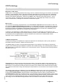

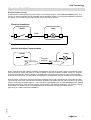

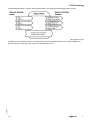
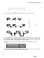


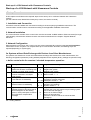
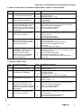

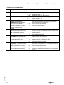


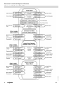
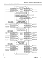
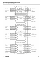

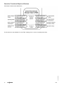

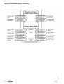

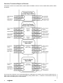
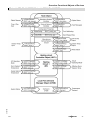


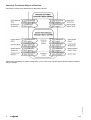

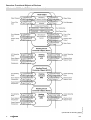
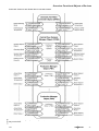
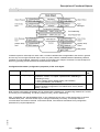
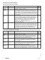
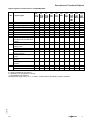
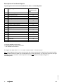

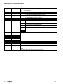
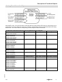
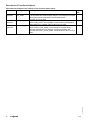
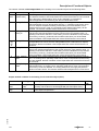


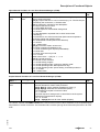

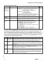
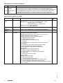
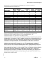
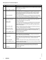

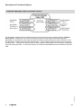
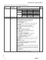
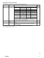
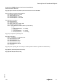
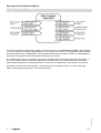

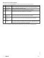
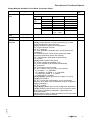

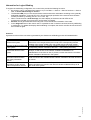
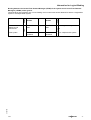

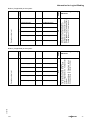
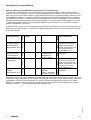


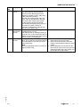

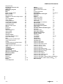
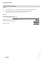
![[7]2.1 MB - Viessmann](http://vs1.manualzilla.com/store/data/006789242_1-8ec4150154a79f40dba494ec59412080-150x150.png)