1
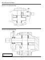
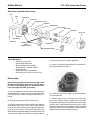
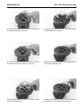
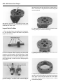
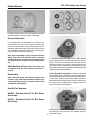
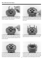
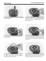
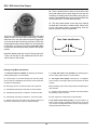
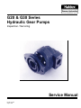
G20 & G30 Series
Hydraulic Gear Pumps
Inspection / Servicing
Service Manual
No. SD - 97105
August 1997
G20 / G30 Series Gear Pumps
G20 Series Cross Sectional Drawing
G30 Series Cross Sectional Drawing
Note: The drawings on this
page are not proportional in
size.
2
G20 / G30 Series Gear Pumps
Haldex Barnes
G20 Series Exploded View Drawing
Nut
Stud
Lockwasher
Front Cover
Square Section O-ring
Seal Gland
Seal Retainer
Center Section
Driven Gear
Wear Plate
Rear Cover
Shaft Seal
Seal Retainer
Shaft Seal
Assembly Notches
(Refer to
paragraph 3 below)
Drive Gear
Wear Plates (G30 Series)
Tools Required
•
•
•
•
•
•
4. Remove key from drive shaft if applicable.
Socket Set (1/2” drive)
Internal Snap Ring Pliers
Shaft Seal Sleeve or clear tape
Torque Wrench - 200 lb-ft capacity
Plastic hammer
Torque wrench box end adapters
(Sturtevant Co. P/N BX-11/16 & BX-7/8)
5. Clamp pump across protected ports in large vise or
holding fixture with shaft end up.
Disassembly
Note:The following general instructions apply to both
the G20 and G30 Series gear pumps, the G20 Series
is shown in the photographs. The following instructions also apply to double gear pumps.
1. It is very important to work in a clean work area when
repairing hydraulic products. Plug ports and wash exterior of pump with a proper cleaning solvent before continuing.
6. Loosen and remove the eight nuts and lockwashers
from the stud bolts.
7. Remove pump from vise and place on clean work
bench. Use a plastic mallet to separate the front cover
from the rest of the pump. The two dowel pins which align
the front cover, center section and rear cover are a tight
fit and will require the use of the plastic mallet to separate
these parts. (Do not use a screwdriver or other pry tool to
separate these parts as damage will result).
2. Remove port plugs and drain oil from pump.
3. It is not necessary to mark the outside of pump before
disassembly as the front cover, center section and rear
cover all have notches cast into the edges of these parts.
By lining up the notches of these three parts the pump
will be properly assembled and proper rotation of the pump
will be assured. (Refer to exploded view drawing above).
3
G20 / G30 Series Gear Pumps
Identifying marks
on intersecting teeth
8. Remove front cover. Identify intersecting teeth of drive
and driven gears with a marking fluid before removing
from pump. Carefully remove drive gear from pump and
place on work bench.
11. Remove the eight studs from rear cover.
9. Remove driven gear from pump and place on clean
work bench.
12. Remove wear plate from rear cover.
10. Remove center section from pump .
13. Remove seal retainer from rear cover and discard as
it will be replaced as a new part.
4
G20 / G30 Series Gear Pumps
Haldex Barnes
14. Remove the seal gland from rear cover and discard
as it will be replaced as a new part.
17. Remove seal retainer from front cover and discard as
it will be replaced as a new part.
15. Remove square cross section o-ring from rear cover
and discard as it will be replaced as a new part.
18. Remove seal gland from front cover and discard as it
will be replaced as a new part.
16. Remove wear plate from front cover. Remove rubber
plug from seal weep hole.
19. Remove square cross section o-ring from front cover
and discard as it will be replaced as a new part.
5
G20 / G30 Series Gear Pumps
gear teeth are sharp, they will mill into the wear plates. If
wear on the face of the gears has occurred, the gears
must be replaced.
20. Remove seal retainer if applicable from front cover
and use a screwdriver or seal removal tool to remove the
shaft seal from front cover.
5. Inspect bearings in front cover for excessive wear,
scoring, flaking or movement of bearings.
Inspect Parts For Wear
1. Clean and dry all parts thoroughly prior to inspection.
It is not necessary to inspect the seals as they will be
replaced as new items.
Check these points
2. Check drive gear spline for twisted or broken teeth,
nicks or excessive wear. Inspect gear journals for
scratches and discoloration. Any discoloration of shaft
requires replacement of drive gear. Inspect gear teeth for
spalding, scratches or excessive wear. Replace if necessary. Light stoning of teeth to remove sharp edges is
permissable.
Check gear face
6. Inspect bearings in rear cover for excessive wear, scoring, flaking or movement of bearings.
Check edge of gear teeth
4. Inspect gear face of both the drive gear and driven
gear for scoring or excessive wear. If the face edge of
6
7. Inspect the gear pockets inside the center section. It is
normal for the surface inside the gear housing to show a
clean “wipe” on the inside gear pocket wall on the intake
side. There should not be excessive wear or deep
scratches and gauges.
G20 / G30 Series Gear Pumps
Haldex Barnes
G20 Wear Plate
G30 Wear Plate
8. Inspect bronze side of both wear plates for erosion,
pitting, scratches or scoring, replace if damaged.
Contents of typical G20 Series Seal Repair Kit.
General Information
It is important that the relationship of the front cover,
center section and rear cover is correct. Notches cast
into the outside surface of these three parts must be
aligned for proper reassembly of this pump. Failure to properly assemble this pump will result in low flow, low pressure and possible damage to the pump.
Note: Upon reassembly of pump, all parts should be
lightly oiled with clean hydraulic fluid or approved
assembly fluid. Use small amounts of graphite grease
to hold seal retainer and seal in place during assembly.
1. Install new shaft seal in front cover, make sure the
spring loaded member of shaft seal faces the inside of
pump. Press the seal into the seal bore until the seal
reaches the bottom of the bore. Uniform pressure must
be used to prevent misalignment or damage to the seal.
Retain with retaining ring if applicable. Coat seal land with
graphite grease after installation.
Shaft Rotation of Pump (Note: This pump is not
bi-rotational and the shaft rotation cannot be reversed).
Double Shaft Seal arrangement - Install first shaft seal
and retaining ring as instructed in the paragraph above.
Next install a new outer shaft seal which has a larger O.D.
in seal cavity. Make sure the spring loaded member of
shaft seal faces the inside of pump. Uniform pressure must
be used to prevent misalignment or damage to the seal.
Press until seal is seated properly.
Reassembly
(Note: New seal glands, seal retainers, square cross
section o-rings, shaft seals should be installed upon
reassembly of pump and are included in the seal kits
available for these pumps).
Seal Kit Part Numbers:
866855 - Standard Seal Kit for G20 Series
Gear Pump.
920097 - Standard Seal Kit for G30 Series
Gear Pump.
7
2. Place rear cover on clean work bench with seal cavity
area facing up. Coat seal cavity with graphite grease to
hold seals in place.
G20 / G30 Series Gear Pumps
3. Coat both the seal gland and plastic seal retainer with
graphite grease. Carefully install the seal gland in the
groove in the seal retainer, make sure the seal gland is
seated completely in the seal retainer.
6. Apply a light coating of graphite grease to the square
cross section o-ring and carefully install in groove in rear
cover. Be very careful that the o-ring does not twist in the
groove, it must be flat in the groove or the pump will leak
at this seam.
4. Install the assembled seal gland and seal retainer in
the cavity in the rear cover. Very carefully press this assembly in place until it is firmly seated in the machined
recess. This is important for proper installation of the
bronze wear plate.
7. Install the eight studs in the rear cover. The course
thread end of the studs thread into the rear cover. Torque
studs to 300-420 lb-in / 25-35 lb-ft / or 33.9 - 47.5 Nm.
5. Lubricate the bronze face of the wear plate and install
over the seal retainer. When properly placed the bronze
face will be next to the gears and flush with the surface of
the rear cover. This photo shows the G20 wear plate, the
G30 wear plate covers the full surface of the cover plates.
8. Install center section over studs, make very sure the
notches are in alignment with the notch in the rear cover.
It may be necessary to use a plastic mallet to seat the
center section due to the tight fit of the dowel pins.Hold
the wearplate in position while tapping center section.
8
Haldex Barnes
G20 / G30 Series Gear Pumps
9. Lubricate the drive gear and driven gear and install the
gears in the proper bearings in the rear cover. Align marked
gear teeth at this time.
12. Install the assembled seal gland and seal retainer in
the cavity in the front cover. Very carefully press this assembly in place until it is firmly seated in the machined
recess. This is important for proper installation of the
bronze wear plate.
10. Place front cover on clean work bench with seal cavity area facing up. Coat seal cavity with graphite grease to
hold seals in place.
13. Apply a light coating of graphite grease to the square
cross section o-ring and carefully install in groove in front
cover. Be very carefull that the o-ring does not twist in the
groove, it must be flat in the groove or the pump will leak
at this seam.
11. Coat both the seal gland and plastic seal retainer
with graphite grease. Carefully install the seal gland in
the groove in the seal retainer, make sure the gland is
seated completely in the seal retainer.
14. Lubricate the steel side of the bronze wear plate with
graphite grease and install over the seal retainer. When
properly positioned, the bronze face will be next to the
gears and flush with the surface of the front cover.
G20 / G30 Series Gear Pumps
16. Place a small amount of clean oil in the inlet of the
pump and rotate the drive shaft away from the inlet one
revolution. No binding should be evident during this operation. The breakaway torque to turn the drive shaft must
not exceed 35 lb-ft / 47.5 Nm after assembly.
17. The name plate located on the end cover contains
the build date code and the model number. Please refer
to this information when corresponding with the
Barnes Hydraulics Service Department.
15. Place a seal sleeve (sleeve must be used with keyed
shafts) or tape over drive shaft end and very carefully
slide front cover over drive shaft and studs. Engage front
cover over dowel pins. Press firmly until front cover is fully
seated against center section. Make sure all notches are
in alignment, if not pump is incorrectly assembled. Make
sure all seals and wear plate have stayed in their proper
position.
Date Code Identification:
3 4 97
Month
Year
Week of Month
Install lock washers and nuts on studs. Torque nuts to 6575 lb-ft / 88-101 Nm on G20 models and 145-155 lb-ft /
196-210 Nm on G30 models.
Placing Pump Back Into Service
1. If shop test stand is available, the following procedure for
testing rebuilt pumps is recommended:
2. If shop test stand is not available, the following procedure for testing rebuilt pumps is recommended:
A. Mount pump on test stand making sure that the proper
level of clean oil is available in the reservoir. Check suction line
for leaks and obstructions.
A. For engine driven pumps, mount pump on equipment
and run pump at 1/2 engine speed at zero pressure for three
minutes.
B. Start pump and run for three minutes at zero pressure.
B. By operating control valve, build pressure intermittently for
three minutes.
C. Intermittently load pump to 500 P.S.I. for three minutes.
D. Intermittently load pump to 1000 P.S.I. for three minutes.
C. Increase engine speed to full throttle and build pressure
intermittently for three minutes.
E. Intermittently load pump to 2000 P.S.I. for three minutes.
D. Stop engine and check pump for external leaks.
F. Remove pump from test stand and check for freeness of
drive shaft. Check pump for signs of external leakage.
E. For electric motor driven pumps, run pump at little or no
load for three minutes, gradually increase load on pump and
cycle each succeeding load for three minutes. Check pump for
external leaks after break-in test.
10
G20 / G30 Series Gear Pumps
Haldex Barnes
Single or Double Pump Trouble Shooting
PUMP TROUBLE
PROBABLE CAUSE
REMEDY
1. Pump does not develop full pressure.
a. System relief valve set too low or leaking.
b. Oil viscosity too low. (oil too thin)
c. Pump is worn out.
d. Seal Retainer O-ring pinched.
a. Check system relief valve for proper setting.
b. Change to proper viscosity oil.
c. Repair or replace pump.
d. Disassemble pump and check o-ring.
2. Pump will not pump oil.
a. Reservoir low or empty.
b. Suction strainer clogged.
c. Incorrect shaft rotation.
a. Fill reservoir to proper level.
b. Clean suction strainer.
c. Check for proper rotation of pump shaft.
3. Noisy pump caused by cavitation.
a. Oil too thick.
b. Oil suction filter plugged.
c. Suction line plugged or too small.
a. Change to proper viscosity.
b. Clean filters.
c. Clean line and check for proper size.
4. Oil heating.
a. Oil supply low.
b. Contaminated oil.
c. Setting of relief valve too high or too low.
d. Oil viscosity too low.
a. Fill reservoir to proper level.
b. Drain reservoir and refill with clean oil.
c. Set to correct pressure.
d. Drain reservoir and fill with proper viscosity.
5. Foaming oil.
a. Low oil level.
b. Air leaking into suction line.
c. Wrong kind of oil.
a. Fill reservoir to proper level.
b. Tighten fittings, check condition of line.
c. Drain reservoir, fill with non-foaming oil.
6. Shaft seal leakage.
a. Worn shaft seal or cut seal lip.
b. Worn shaft in seal area.
c. Wrong pump shaft rotation.
a. Replace shaft seal.
b. Replace drive shaft and seal.
c. Check for proper rotation of pump shaft.
NOTES
11
G20 / G30 Series Gear Pumps
AUTHORIZED DISTRIBUTOR
214 JAMES FARM ROAD
STATESVILLE, NC 28677 USA
PHONE: (704) 873-2587
FAX, SERVICE DEPT.: (704) 838-7987
Form No. SD-97105
2222 - 15TH STREET
ROCKFORD, IL 61104 USA
PHONE: (815) 398-4400
FAX, SERVICE DEPT.: (815) 398-9817
FAX, SALES DEPT.: (815) 398-5977
Copyright Barnes Hydraulics 1997
All Rights Reserved
Printed in USA
POSTFACH 1507 • 95014 HOF
SELIGENWEG 12 • 95028 HOF
GERMANY
PHONE: (49) 9281 8950
FAX: (49) 9281 87133
RINGVAGEN 3 • BOX 95
S-280 40 SKANES FAGERHULT
SWEDEN
PHONE: (46) 433 302 90
FAX: (46) 433 305 46