1
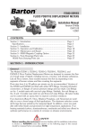
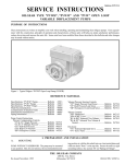
F500 SERIES
FLOCO POSITIVE DISPLACEMENT METERS
Installation Manual
Version 02E65a
ID#11500
5/2002
CONTENTS
Section 1 - Introduction ..........................................................
Section 2 - Installation ............................................................
Section 3 - Operation and Calibration ......................................
Section 4 - Maintenance and Repair ........................................
Section 5 - M500 Magnetic Coupling Option............................
Section 6 - Parts Drawings/Parts Lists......................................
M500 Parts Drawing/Parts List ...........................................
Page 1
Page 4
Page 9
Page 12
Page 17
Page 23
Page 30
SECTION 1 - INTRODUCTION
General
The Models F500-1, F500-2, and F500-3 Floco Positive Displacement Meters
are designed to measure the flow of a broad range of liquids, including viscous,
corrosive, and abrasive substances. Like all Floco meters, these models measure
the flow by separating it into segments of known volume and then counting
the segments. The rotor design allows small soild particles and sediment to pass
through without causing damage or malfunction. Bridge seals prevent liquid from
passing to the outlet port without being measured.
F500-1 and F500-2 have identical parts, except for housing thread connections.
The Model 500 Magnetic Coupling Assembly is used on the register side of the
meter. A low pressure seal is used on the sampler side when a sampler is used
(see FRA Sampler manual for details). F500-3 parts are identical to the F500-1
and -2, except for the sideplate assemblies.
Floco Positive Displacement Meters are made up of five basic components:
body, bridge, rotor, side plates and register. The fluid passing through the
meter is divided into segments by the blades of the rotor. Three segments pass
through the meter each time the rotor completes a revolution. By counting rotor
revolutions, a measure of the fluid is obtained.
SAFETY
Before installing this instrument, become familiar with the installation instructions
in Section 2. WARNING notes that appear on the following pages of this manual
should be reviewed before proceeding: NONE.
Liquid entering the meter is deflected downward by the bridge against the rotor
blades. The force of the liquid on each successive blade causes the rotor to turn.
The liquid between the blades is moved to the outlet port, where it is discharged
as the bridge reduces the volume of the flow segment.
The rotor is magnetically coupled to the register drive shaft which is connected
to the register by appropriate calibration gears. The design of the rotor allows
small particles to pass through the meter without causing damage or malfunction.
Performance Data
The graphs on the next page can be used as a guide in selecting the appropriate
Floco meters for a particular application.
Meter Accuracy with Various Component Materials
This graph shows the relative effect on the accuracy of the four most popular
combinations of bridge and elastomer materials for a fluid of 100 SSU, and a
two-inch Floco Industrial Meter. The pressure drop across the meter was not
effected by changing bridge and elastomer material.
An increase in the viscosity would flatten these curves, while a decrease in the
viscosity would cause the curves to droop more, but the relative positions would
remain the same.
The steel bridge and Buna-N elastomer gave the best accuracy over the full
range of the meter.
By selecting the proper calibration gears, it is possible to calibrate the meter for
optimum accuracy on the fluid being measured at the normal operating point.
Similar curves on the three-inch Floco Industrial Meter would show the same
relative relations.
Accuracy and Pressure Drop
The next two graphs show the relationship of flow rate, pressure drop across
the Floco meter, and accuracy for fluids of various viscosities flowing in a meter
with a steel bridge, stainless steel rotor, and teflon elastomers. The viscosities
used were 44,100 and 400 SSU.
Water at 68°F has a viscosity of 31 SSU, which would give curves for accuracy
and pressure drop very close to those of the 44 SSU viscosity tested.
The steel bridge, stainless steel rotor, with teflon elastomers was selected as it is
being used more and more on industrial applications on corrosive fluid. When
the fluid is abrasive, the elastomers should be changed to Viton or Buna-N, if
fluid compatibility will allow. The customer is actually in the best position to
determine the choice of materials compatible with his service. You should advise
him of the material available and let his experience help determine the proper
choice of material.
A review of the Accuracy and Pressure Drop graphs will show that the pressure
drop on the three-inch Floco meter is about 50% of the pressure drop on
the one- and two-inch Floco meters. If this parameter is more important than
the slight difference in accuracy and cost, then the three-inch size should be
recommended.
Measurements have been made which indicate that Floco meters will work well
with fluid viscosities at least as high as 10,000 SSU.
2
3
SECTION 2 - INSTALLATION
Unpacking
Check the shipment for damage and, if any is noted, file a claim with the.
transportation company and notify the nearest Barton Sales Office as soon as
possible.
Precautions
The following precautions must be observed to assure safe and effective performance of Floco meters:
Lines: The flow lines upstream of the Floco meter should be purged to remove
scale, rocks, welding slag or other debris prior to installing the meter, if no
bypass manifold is used.
Control Valves: Control valves should be opened slowly to permit charging
of the Floco meter with liquid before normal operation begins. Sudden surges
of pressure or gas can severly damage the Floco meter assembly if the valves
are not opened slowly.
Liquids with Gas or Vapor: If the liquid to be measured contains gas or
vapor, a separator or air eliminator must be used ahead of the Floco meter to
prevent rotor damage.
Mounting
The meter may be mounted either horizontally or vertically. When mounting
horizontally, orient the nameplate upward. When mounting vertically, the liquid
flow should be downward.
Typical Installations (pages 5-8)
Separators (page 5)
1. The meter may be mounted on any liquid/gas separator that has been or
may be adapted to liquid level controllers.
2. Liquid level height should be maintained at least 18 inches above liquid
outlet.
3. The liquid level control valve should always be downstream from meter.
4. Isolation valves and a bypass manifold should be included in the mounting
assembly to permit normal operation if meter repairs are necessary.
4
Typical Installations (continued)
5
Typical Installations (continued)
Oil Treaters
1. The Floco meter may be mounted on both oil and water outlets. The
downcomer in either case should be at least two times flow line pipe
diameter, and never less than 4 inches O.D..
2. The liquid level in each downcomer should be adjusted so that minimum
liquid height after dump is six feet.
3. Liquid level control valves should always be downstream from the meter.
4. Throttling controls should not be used.
5. The meter manifold should include a bypass with isolation valves to permit
normal operation if meter repairs are necessary.
Flow Line (page 7)
1. The meter may be mounted in a flow line, but should have a control valve or
back pressure valve downstream from the meter.
2. The meter manifold should include a bypass manifold with isolation valves
to permit normal operation if meter repairs are necessary.
6
3.
Where gas or air is present in the flow line, a gas eliminator should be
installed ahead of the meter.
7
Typical Installations (continued)
Waterflood Injection
1. The meter may be mounted either near the injection well or in a meter
manifold near the injection pump.
2. The meter manifold should include a bypass manifold with isolation valves
to permit normal operation if meter repairs are necessary.
3. The flow rate control valve should always be installed downstream from
the meter.
4. If pulsation or vibration is possible, a pulsation dampener should be installed
ahead of the meter. Severe pulsation can cause rotor damage.
8
SECTION 3 - OPERATION/CALIBRATION
Startup Procedures (General)
Specific application procedures are on pages 4-8.
1. Start with isolation valves closed.
2. Permit flow through the bypass for a time sufficient to purge the flow lines
of gas and other undesirables. During the startup phase, adjust the liquid
level controls (where applicable).
3. Open the isolation valve ahead of the meter slowly to equalize the pressure
across the meter.
4. Open the downstream isolation valve or control valve slowly to allow the
meter to start operating.
5. Close the bypass valve.
6. Adjust downstream control valve to obtain proper flow rate through meter.
NOTICE: The Floco meter does not normally require an upstream strainer.
However, in applications where large solid fragments may enter the flow lines,
a filter may be used without modifying the meter. If the liquid stream contains
dissolved gas or vapors, a gas eliminator should be installed ahead of the meter.
Proving
The Floco Positive Displacement Meter may be calibrated by three proving
methods: Gravimetric Proving, Volumetric Proving, or Master Meter Proving.
Meter proving by any method is basically a laboratory operation and should be
performed carefully to obtain accurate data and exact mathematical calculations.
(Refer to American Petroleum Institute API Standard 1101, August 1960.)
A. Gravimetric Proving
A method used when the metered liquid contains entrained gas or vapor,
paraffin, wax, sand or other solids, or is heavy or viscous.
This method requires careful weighing of the quantity of liquid that passes
through the meter. The net weight of the metered liquid is converted to
volume (corrected for temperature and pressure where necessary). The
metered volume is compared to the computed volume and the correct meter
factor is obtained.
B. Volumetric Proving
A method that requires fewer calculations than Gravimetric Proving; therefore, requires less time to perform. However, errors may result if the liquid
is viscous or contains entrained gas or vapor, solids, paraffins, or other
impurities which may adhere to the calibrating vessel.
This method requires the use of a vessel calibrated for a known volume. The
calibration vessel must be cleaned thoroughly before and after each use. The
metered volume through the meter is compared to the true volume of the
calibrated vessel to obtain the correct meter factor.
C. Master Meter Proving
A method that requires installing a meter of known accuracy into a prover
loop. The readings of the production meter (meter being calibrated) are
compared after the test with the readings of the master meter.
9
Calibration
After the meter is proved and the true volume and meter volume are obtained,
the meter may be calibrated by changing two nonslip, positive-drive change
gears, located between the register assembly and the gear case assembly. These
gears may be changed while the meter is in operation.
Selection
Selection of the correct change gears is done by dividing the true volume into
the metered volume:
True Volume: 100 barrels (gallons, liters, etc.)
Metered Volume: 104 barrels (gallons, liters, etc.)
104/100 X 100 = 104% (now being registered)
The tables that follow indicate gear changes required to calibrate meteres to
approximately 100% accuracy when percent registered is known.
Example: The Floco meter registers 104 barrels. True volume is 100 barrels.
Using formula above, % registered is calculated to be 104%. For a one- or twoinch meter, the 0.670-30 driven gear and the 0.670-26 drive gear will return
the meter to approximately 100% accuracy. For a three-inch meter, gears would
change to 0.460-22 and 0.860-38. These charts are correct only if % registered
is calculated from meters with standard gears, as underlined in the two charts.
Accuracy
It must be noted that all positive displacement meters require a meter factor
number for extreme accuracy. The meter factor number may be determined by
dividing the true (calculated) volume by the metered volume:
True Volume /Metered Volume = Meter Factor
The metered volume for future accounting is then multiplied by the meter factor
to obtain the true volume: True Volume x Meter Factor = True Volume
10
11
SECTION 4 - MAINTENANCE AND REPAIR
Maintenance
Regular inspection and preventive maintenance of Floco meters will ensure a
long and trouble-free service life. The following procedure is suggested as a
maintenance program. However, this program should be adapted to the type of
liquid metered, based on corrosive and abrasive qualities.
1. Inspect the register assembly semi-annually: All gears shall turn freely and
assembly shall be free of scale and corrosion.
2. Lubricate magnetic coupling and gears with one ounce of light oil.
3. If the meter accuracy changes, inspect the rotor assembly. Inspect specifically the edges of the hinges and the rotor hub (where a positive seal
is required) for separation or splitting of the elastomer. Replace the rotor
blades or rotor body if splitting or separation of the elastomer is apparent or
if portions of the elastomer are missing.
4. Inspect bearings every 25,000 barrels (4,000 cubic meters) for excessive
wear. Tests on brine indicate satisfactory service even after metering
100,000 barrels (16,000 cubic meters). Replace bearings if rotor shafts
become scored, if bearings surface shows excessive wear, or if bearing
becomes out of round.
5. Inspect bridge and bridge seals semi-annually or whenever sideplate is
removed. Bridge seals should not be split, chipped or elongated.
6. Liners should be inspected annually for excessive wear or scoring. If liner is
excessively worn, replace with new liner (refer to para. A. Body on next
page). If slightly scored, the liner may be polished with a fine emery cloth.
7. Inspect the wearplates whenever the sideplate is removed or whenever the
meter accuracy varies. If the wearplates show excessive wear (worn through
chrome plating), reverse or replace the plates. Do not confuse a normal
wear pattern with excessive wear. The rotor will normally wear a pattern
on the wearplate.
Tools Required For Maintenance And Troubleshooting
12
Troubleshooting
NOTE: Visual inspection of the rotor assembly and the magnetic coupling will
reveal most causes of malfunctions in the Floco Meters.
Problem
Possible
Sources
Probable Cause
Corrective Action
Rotor Hinge
Broken Hinge
Replace Hinge
Broken or Worn Shaft
Replace Rotor Body
Inspect Bearing Surfaces (wear of
these surfaces may be the cause of
shaft failure)
Rotor Shaft
No Flow
Indication
Remove Register and observe worm
gear.
Magnetic
Coupling
Slipping Magnetic Coupling
If it is rotating, check register for
excessive drag. Determine the cause
and correct.
If worm gear is not rotating, trouble is
in magnetic coupling.
Low Flow
Indication
Bypass
Valve
Valve Leak
Repair or Replace Valve
Wearplates
Plate Worn
Reverse or Replace Wearplates
Calibration
Gears
Worn or Incorrect Gears
Replace Gears
Bridge Seals Worn Seals
Rotor Hinge
High Flow
Indication
Excessive
Rotor Spin
Replace Bridge Seals
Worn or Broken Hinges
Replace Hinges
Slow Closing Rotor Hinges due to large
change in viscosity of service fluid
Recalibrate Meter Using Service Fluid
Gas in Liquid
Install Gas Eliminator ahead of meter
or raise liquid level in vessel to a
height sufficient to prevent gas flow.
Inspec Rotor Assembly for wear or
damage.
Repair Procedures
Numbers in parentheses (#) are items in parts drawing/lists starting on page 23.
A. Body
1. Remove the sideplates (9) and the rotor assembly (18).
2. Remove bridge screws (28) and washers (29) using 7/32-inch hex key.
3. Remove the bridge (25).
4. Remove the liner wedge (19), by prying out with a screwdriver.
5. Remove the liner (17). The liner should slide out of the body freely.
6. Clean the meter body by removing scale deposits or rust with a wire
brush and emery cloth. Apply a thin coat of rust inhibitor to all
machined surfaces.
7. Replace the liner. Attach one sideplate assembly with three bolts, but
without the O-ring. Insert the liner, positioned with its edges equally
spaced from the bridge screws and snug against the sideplate.
8. Insert the wedge (19) between the bridge screws with the wedge apex
against the bridge.
9. Insert the bridge with the screws very loose.
13
10. Tighten the bridge screws evenly until the wedge is slightly flattened.
Check the liner clearance to the sideplate with a 0.0015” to 0.002”
feeler gage. If the feeler gage slides beneath the liner, tap the liner (with
a hardwood or plastic mallet). Tighten the bridge screws until the bridge
is snug against the liner.
11. With the liner wedged in place, remove the bridge and sideplate. Dress
the edges of the liner until they are smooth and flush with the meter
body facings.
12. Replace the bridge, leaving the bridge screws loose. Do not tighten the
bridge screws until the sideplate assemblies are attached and snug. The
sideplates will align the bridge in the correct position when the bridge
screws are tightened.
13. Replace the bridge seals (24) and body seal O-rings (20).
14. Proceed to further assembly as required.
B. Rotor
Inspect all rubber covered parts. Some visible wear is normal and will not
affect the accuracy of the meter. If the rubber coating is missing from any
part, replace the part.
Inspect for broken springs, broken or missing boots, missing or damaged
rotor blade hinge grommets.
Replacement of hinge assemblies:
1. Remove retaining clips (14) from hinge pins (13).
2. Remove hinge pins with pliers allowing hinges, springs and grommets
to be removed.
3. To assemble rotor, insert hinge pin in appropriate hole in web so that
hinge arm will slip on.
4. Insert spring with grommets in place so that holes are aligned with pin.
5. Insert hinge pin through all grommet holes and through pin hole in
opposite web.
6. Hold hinge pin firmly in place and insert retaining clip.
NOTICE
Hinge pin should be firmly in place without wobble or lateral movement.
7. Repeat steps 1 through 6 for each hub section.
C. Sideplate
NOTE: Sideplate bushings are designed with left-hand threads.
1. Remove register and register adapter, magnetic coupling assembly, or
blind nut from sideplate.
2. Unscrew bearing nut (6) with a wide blade screwdriver.
3. Slide out bearing assembly.
4. Remove wearplate (30) from the sideplate.
5. Remove O-ring (56).
6. To remove bushing, place sideplate face down on flat surface such as 2
x 8-inch wood block with a 1/2-inch O.D. hole bored in wood.
Continued on next page...
14
7.
Using bushing insertion tool 1434 or similar flat tool, place tool against
bushing and tap sharply with a small hammer. The bushing is pressed
in place and will fall out easily when the pressure is released.
8. To replace bushing, turn sideplate face up, insert the bushing using tool
1434, and tap with small hammer until bushing is flush with sideplate
face. Do not dent or sear bushing or sideplate. Bushing must be flush
with sideplate to within 0.003 of an inch.
9. Replace O-ring (5) and wearplate (30).
10. Insert bearing assembly (12) taking care that bearing sleeve lugs fit into
lug slots in bushing.
11. Insert and tighten bearing nut (6).
D. Magnetic Coupling
Note: Reference parts drawing and list pages 30-31.
1. Remove driven magnet assembly.
2. Remove flange bearing from housing bearing assembly. Do not beat
end of housing bearing assembly on hard surface to remove bushing. Instead, use small needle nose pliers with smooth surfaces that will
not damage the bearing.
3. Remove drive coupling and shaft assembly with drive magnet as one
unit from the housing bearing assembly.
4. Remove all O-rings.
5. Remove retaining ring with flat surface of standard screwdriver or
E-018 Truarc applicator and slide drive magnet off end of drive
coupling and shaft assembly.
6. Clean parts with petroleum cleaning (Stoddard) solvent.
7. Inspect all parts for excessive/uneven wear. Replace all worn parts.
8. Place a drop of oil on each O-ring and work the oil into the surface.
9. Apply a heavy coat of grease to outside of housing bearing assembly.
10. Install 0-ring onto housing bearing assembly.
11. Install drive pin in drive coupling and shaft assembly. Slide drive magnet
over drive coupling and shaft assembly. Secure drive magnet with
retaining ring by using E-018 Truarc applicator. E-ring fits into groove
in the drive coupling and shaft assembly.
12. Slide drive coupling and shaft assembly with drive magnet attached into
housing bearing assembly, aligning end of shaft into bearing in the
inside of bearing housing assembly.
13. Install 0-rings on bushing and then insert bushing (larger inside diameter [approx. 7/16-inch] end first) into bearing housing.
14. Slide driven magnet assembly over housing bearing assembly.
15. Slowly start threading housing bearing assembly onto bushing of register sideplate assembly (left-hand thread) and at the same time rotate
driven magnet assembly back and forth until slot of drive coupling and
shaft assembly is engaged into rotor shaft. If drive coupling and shaft
assembly is not properly engaged onto rotor shaft, housing assembly
will not thread properly and will jam.
15
16. When it is determined that drive coupling and shaft assembly is firmly
engaged onto rotor shaft, continue to thread the housing bearing
assembly onto register sideplate assembly until it is tight against O-ring.
Tighten securely with one-inch open-end wrench. The housing bearing
assembly will move approximately 1/4-inch into bushing of sideplate
assembly when completely tightened.
17. Push register adapter over driven magnet assembly so the worm is in alignment with worm gear and register adapter is tight against the sideplate.
Secure with two 10-32 x 1/2 screws.
18. Re-install calibration gears, register assembly, register gasket and register cover using two screws.
16
SECTION 5 - M500 MAGNETIC COUPLING OPTION
Introduction
The Floco M500 Magnetic Coupling transmits power from the rotor to a
standard small register, small reset register, large numeric reset register/ticket
printer, and other accessories. A magnet on the rotor side is magnetically
coupled to a magnet on the register side — eliminating pressure seals.
The M500 can be installed on applicable meter already in use, provided the
rated torque limit is not exceeded. The register adapter (0000.2931.0) is used
with the F500 Series meters.
M500 Installation
If the M500 was ordered separately, turn worm gear by hand and check that the
drive coupling (0500.1024.B) and shaft assembly rotates.
Make sure the torque demanded from the worm in the coupling is limited to a
maximum of 12 ounce-inches.
Tools Required for Installation and Repair:
• 7/8-inch open-end wrench (to remove LP seal housing)
• 1-inch open-end wrench (to install magnetic coupling)
• Standard Screwdriver (for removal of screws)
• Can of lightweight Oil (Lubrication)
• E-018 Truac Applicator (to remove retaining rings)
• 1/32-inch Pin Punch & Small Ballpeen Hammer (to remove/install worm pin)
Note: Letters in parentheses (X) correspond to items in illustration on page 18.
A. Preliminary Procedure
The following preliminary procedure is necessary to mount the magnetic
coupling on the applicable meter if the coupling was ordered as a separate
item. If a complete meter was ordered with the magnetic coupling included,
omit the mounting instructions in this supplement and mount the entire
meter as directed in the installation section of the applicable technical
manual.
1. Close isolation valves upstream and downstream from the Floco meter.
2. Relieve pressure from Floco meter, using a method suited to the
particular installation.
B. Removal of Low Pressure Seal Assembly (Refer to page 18)
1. Remove the two 10-32 x 1/2 screws (B) that secure register box
assembly (A) to the register adapter assembly (H), lift off register box
assembly, register gasket (C), and register assembly (D), and remove
drive calibration gear (E) from register adapter assembly.
2. Remove the two 10-32 x 1/2 screws (I) that secure register adapter
assembly (H) over low pressure seal.
3. Using a 7/8-inch open-end wrench, remove low pressure seal housing
(left-hand thread) from register sideplate assembly (M).
C. Mounting the Model 500 Magnetic Coupling
1. Remove coupling housing (L) from register adapter (H).
17
2.
18
Slowly start threading coupling housing Q onto bushing of register
sideplate assembly (M) (left-hand thread) and at the same time rotate
worm (J) back and forth until slot of drive coupling and shaft assembly
(N) is engaged onto rotor shaft (0). If drive coupling and shaft assembly
is not properly engaged onto rotor shaft, housing assembly will not
thread properly and will jam.
C. Mounting the Model 500 Magnetic Coupling (Continued)
3. When it is determined that drive coupling and shaft assembly (N) is
firmly engaged onto rotor shaft (0), continue to thread coupling housing
(L) onto register sideplateassembly (M) until coupling housing is tight
against 0ring. Tighten securely with 1-inch open-end wrench. Coupling
housing (L) will move approximately V4 inch onto bushing or sideplate
assembly to be completely tightened.
4. Push register adapter (H) over coupling housing (L) so that magnetic
drive assembly and worm (J) is in alignment with worm gear (G) and
tight against flange of sideplate assembly (M), and secure with two
10-32 x 1/2 screws. If necessary, install worm gear assembly (G) in
register adapter.
5. Install drive calibration gear (E) which was previously removed onto
end of split shaft of worm gear assembly (G), with small hub of gear
facing up.
6. Place register assembly (D) over register adapter assembly (H), set
register gasket (C) in flange of register assembly, place register box
assembly (A) over register assembly, and secure with the two 10-32
x 1/2 screws.
M500 Troubleshooting And Repair
Servicing
The servicing information in this section refers only to the Model 500 Magnetic
Coupling, which has replaced the low-pressure seal. To service those portions of
the meter that were not changed by the installation of the magnetic coupling,
refer to the applicable sections or pages as directed.
Troubleshooting Suggestions
If regularly maintained, Floco meters will provide long trouble-free service. If
trouble becomes evident, the source of trouble will usually be found in the
magnetic coupling, rotor assembly, or bearings.
Maintenance
A. Register Removal (refer to page 18)
Regular inspection and preventive maintenance on the magnetic couplings
of Floco meters, in addition to the prescribed maintenance of the other
major parts of the meter, will ensure many months of trouble-free service.
It is suggested that the following maintenance program be performed
semiannually. However, this program should be adapted to the type of liquid
metered, based on corrosive and abrasive qualities. Only the maintenance
of the magnetic coupling is described in detail in this supplement; refer to
the maintenance section in the main portion of the manual as directed for
maintenance of other parts of the meter.
Remove Register as follows:
1. Close isolation valves upstream and downstream from Floco meter.
2. Relieve pressure on meter.
19
3.
Remove screws (B) that secure register box assembly (A) to register
adapter (H), and remove register box assembly, register gasket (C), and
register assembly (D).
4. Remove screws (I) that secure register adapter (H) to register sideplate
assembly (M) of body assembly, and slide register adapter off coupling
housing.
5. Use a 1-inch open-end wrench to loosen coupling housing (L) from
bushing of register sideplate assembly (M) (left-hand thread) and then
continue to unscrew and finally separate coupling housing from sideplate assembly.
B. Magnetic Coupling Maintenance
Refer to the following troubleshooting table for suggestions and inspection
procedures.
Troubleshooting Table:
NOTE: The following procedure assumes that register and magnetic coupling have already been removed from meter and that coupling housing has
been removed from register adapter as previously described.
1. Disassembly of Magnetic Coupling (refer to pages 30-31):
a. Remove magnet drive assembly with worm.
b. Drive out roll pin from worm if necessary to replace with new
worm.
c. Remove bushing from housing bearing assembly. Do not beat end
of housing bearing assembly on hard surfaces to remove bushing.
Remove with small needle nose pliers that have smooth surfaces
so as not to damage bushing.
20
d.
2.
3.
Remove drive coupling and shaft assembly with drive magnet as
one unit from the housing bearing assembly.
e. Remove all O-rings.
f. Remove retaining ring with flat surface of standard screwdriver or
E-018 Truac applicator and slide drive magnet off end of drive
coupling and shaft assembly.
g. Clean parts with petroleum cleaning (Stoddard) solvent.
Inspection of Magnetic Coupling Parts
a. Inspect all parts closely for signs of excessive or uneven wear.
b. Check that drive magnet slot is aligned against drive pin of shaft.
If necessary, push magnet tight against pin and reset retaining ring
with E-018 Truac applicator.
c. Replace all worn parts.
NOTE: Make sure new 0-rings are of the same material as the original
0-rings or of a material compatible with fluid conditions.
Reassembly of Magnetic Coupling:
NOTE: Before reassembling magnetic coupling place one drop of oil
on each 0-ring used in reassembly and work oil onto all surfaces of
0-ring. Lubricate bearing surfaces with oil or good grease lubricant.
a. Install 0-ring onto housing bearing assembly.
b. Install drive pin in drive coupling and shaft assembly. Slide drive
magnet over drive coupling and shaft assembly. Secure drive
magnet with retaining ring by using E-018 Truac applicator.
Retaining ring fits into groove in the drive coupling and shaft
assembly.
c. Slide drive coupling and shaft assembly with drive magnet attached
into housing bearing assembly, aligning end of shaft into bearing in
the inside of bearing housing assembly.
d. Install 0-rings on bushing and then insert bushing into bearing
housing assembly, with end having larger inside diameter (about
7/16”) being inserted first.
e. Install worm over shaft on drive magnet assembly and align holes
for worm pin. Drive roll pin through holes in worm and shaft,
being careful not to bend or distort shaft or assembly.
f. Slide magnet drive assembly over housing bearing assembly).
g. Refer to page 18. Assuming register sideplate assembly (M) has
been reinstalled on body, slowly start threading coupling housing
(L) onto bushing of sideplate assembly (left-hand thread) and at
the same time rotate worm (J) back and forth until slot of drive
coupling and shaft assembly (N) is engaged onto rotor shaft (0). If
drive coupling/shaft assembly is not properly engaged onto rotor
shaft, housing assembly will not thread properly and will jam.
21
B.
22
Magnetic Coupling Maintenance (continued)
h. When it is determined that drive coupling and shaft assembly is firmly
engaged onto rotor shaft (0), continue to thread coupling housing (L)
onto register sideplate assembly (M) until it is tight against 0-ring.
Tighten securely with 1-inch open-end wrench. Coupling housing will
move approximately 1/4-inch onto bushing of sideplate assembly to be
completely tightened.
i. Push register adapter (H) over coupling housing (L) so that magnetic
drive assembly and worm (J) is in alignment with worm gear (G) and
tight against flange of register sideplate assembly (M), and secure with
the two screws (I).
j. Pour enough lightweight lubricating oil into register adapter (H) to
cover approximately half the thickness of toothed section of worm
gear (G).
k. Place register assembly (D) over register adapter (H), set register gasket
(C) in flange of register assembly, place register box assembly (A) over
register assembly, and secure with the two 10-32 x 1/2 screws (B).
NOTE: Drive and driven magnets are of sintered material (very hard) and
could be broken if struck a direct hard blow with a hammer.
SECTION 6 - PARTS LIST/DRAWING
F500
23
SECTION 6 - PARTS LIST/DRAWING (Continued)
F500 Parts List
24
F500 Parts List Continued
25
SECTION 6 - PARTS LIST/DRAWING (Continued)
F500 Parts List Continued
26
F500 Parts List Continued
27
SECTION 6 - PARTS LIST/DRAWING (Continued)
F500 Parts List Continued
28
Large Numeral Register Mounting Assembly Parts List
29
SECTION 6 - PARTS LIST/DRAWING (Continued)
M500 Parts Drawing/Parts List
30
M500 Parts Drawing/Parts List (continued)
31
Product Warranty
A.
Warranty
Cameron International Corporation ("Cameron") warrants that at the time of shipment, the
products manufactured by Cameron and sold hereunder will be free from defects in material and workmanship, and will conform to the specifications furnished by or approved by
Cameron.
B.
Warranty Adjustment
(1)
If any defect within this warranty appears, Buyer shall notify Cameron immediately.
(2)
Cameron agrees to repair or furnish a replacement for, but not install, any product
which within one (1) year from the date of shipment by Cameron shall, upon test and
examination by Cameron, prove defective within the above warranty.
(3)
No product will be accepted for return or replacement without the written authorization of Cameron. Upon such authorization, and in accordance with instructions by
Cameron, the product will be returned shipping charges prepaid by Buyer. Replacements made under this warranty will be shipped prepaid.
C. Exclusions from Warranty
(1)
THE FOREGOING WARRANTY IS IN LIEU OF AND EXCLUDES ALL OTHER EXPRESSED OR IMPLIED WARRANTIES OF MERCHANTABILITY, OR FITNESS FOR
A PARTICULAR PURPOSE, OR OTHERWISE.
(2)
Components manufactured by any supplier other than Cameron shall bear only the warranty made by the manufacturer of that product, and Cameron assumes no responsibility
for the performance or reliability of the unit as a whole.
(3)
"In no event shall Cameron be liable for indirect, incidental, or consequential damages
nor shall the liability of Cameron arising in connection with any products sold hereunder
(whether such liability arises from a claim based on contract, warranty, tort, or otherwise)
exceed the actual amount paid by Buyer to Cameron for the products delivered hereunder."
(4)
The warranty does not extend to any product manufactured by Cameron which has been
subjected to misuse, neglect, accident, improper installation or to use in violation of instructions furnished by Cameron.
(5)
The warranty does not extend to or apply to any unit which has been repaired or altered
at any place other than at Cameron's factory or service locations by persons not expressly
approved by Cameron.
Product Brand
Barton® is a registered trademark of Cameron International Corporation ("Cameron").
MEASUREMENT SYSTEMS
Formerly: NuFlo Measurement Systems • Barton Instrument Systems • Caldon, Inc.
HOUSTON
HEAD OFFICE
ASIA
PACIFIC
281.582.9500
603.2287.1039
[email protected]
NORTH
AMERICA
EUROPE,
MIDDLE EAST
& AFRICA
1.800.654.3760
[email protected]
44.1243.826741
[email protected]
USA • CANADA • UK • SCOTLAND • CHINA • UAE
ALGERIA • MALAYSIA • SINGAPORE • www.c-a-m.com/flo