1
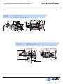
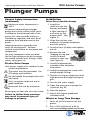
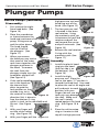
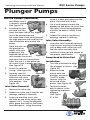
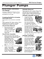
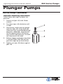
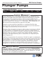
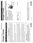
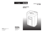
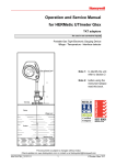
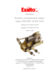
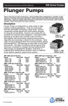
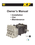
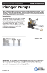
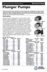
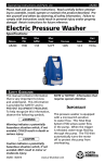
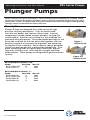
Operating Operating Instructions Instructions and and Parts Parts Manual Manual RSV RSV Series Series Pumps Pumps Plunger Pumps Please read and save these instructions. Read carefully before attempting to assemble, install, operate or maintain the product described. Protect yourself and others by observing all safety information. Failure to comply with instructions could result in personal injury and/or property damage! Retain instructions for future reference. Description Plunger Pumps are designed for a wide variety of high pressure washing applications. They are constructed with die-cast bodies and feature a brass head. Internal components include coated ceramic plungers for long life and durability. Precision cast cooling fins are anodized for maximum heat dissipation. Oversized needle bearings on the drive side, and ball on the non-drive side together with the precision supports assure positive alignment and centering in relation to the crankcase. Valve cages of special designed Ultra-Form provide positive seating and extended life. Onepiece connecting rods are special alloy aluminum, bronze rods over 4,000 psi units, oversized for strength and load disbursement. These pumps are designed for gasoline driven systems. Figure 1 Hollow Shaft Figure 2 Hollow Shaft RSV 3400 rpm D Version - 3/4” Model Max GPM Max PSI RSV2.5G25D-F25 2.5 2500 RSV3G25D-F25 3 2500 RSV 3400 rpm D Version - 1” Model Max GPM Max PSI RSV3G35D-F40 3 3500 RSV3.5G35D-F40 3.5 3500 RSV4G40D-F40 4 3000 RSV4G40D-F40 4 4000 NORTH AMERICA Form RSV-OM 0607 First Choice When Quality Matters High Performance Pumps RSV Series Pumps Operating Instructions and Parts Manual Plunger Pumps $ VERSION & (OLLOW SHAFT PUMP v 236 $ VERSION & (OLLOW SHAFT PUMP v 2 2 ª ª ' ' ' 236 . ª NORTH AMERICA First Choice When Quality Matters RSV Series Pumps Operating Instructions and Parts Manual Plunger Pumps Formulas Nozzles: Impact Force (lbs.) = .0526 x GPM x √PSI Nozzle # = GPM x 4000 √ PSI GPM= Nozzle # x PSI √4000 PSI = (GPM/Nozzle #)2 x 4000 Horse Power: GPM x PSI = Hydraulic HP 1714 GPM x PSI = EBHP 1457 EBHP x 1457 = GPM PSI EBHP x 1457 = PSI GPM HP loss due to altitude = 3% per 1000 FT above sea level Pump Speed and Flow: Rated GPM = Desired GPM Rated RPM Desired RPM Conversions Gallons x 3.785412 = Liters Gallons x 128 = Oz. PSI x .06896 = Bar Bar x 14.5038 = PSI 1 inches = 25.4 millimeters Liters x .2642 = Gallons (US) Ft. Lbs. x 1.356 = Newton Meters Inch Lbs. x .11298 = Newton Meters Newton Meters x .737562 = Ft. Lbs. (force) Newton Meters x 8.85 = In. Lbs. (force) Temperature = 1.8(C° + 17.78) = F°,.555(F° - 32) = C° 1 U.S. Gallon of freshwater = 8.33 lbs. 1 PSI = 2.31 feet of water 1 PSI = 2.04 inches of mercury 1 Foot of water = .433 PSI 1 Foot of water = .885 inches of mercury 1 Meter of water = 3.28 feet of water Kilograms x 2.2 = Lbs. Motor Pulley Ø = Pump Pulley Ø Pump RPM Motor RPM General Safety Information WARNINGS Gasoline Drive Pumps The pump is designed to pump nonflammable or non-explosive fluids. These pumps are intended to pump clean filtered water only. Do not operate in or around an explosive environment. Always wear safety glasses or goggles and appropriate clothing. Do not alter the pump from the manufacturers design. Do not allow children to operate the pump. Never point the high-pressure discharge at a person, any part of the body or animals. Do not operate gasoline engines in a confined area; always have adequate ventilation. Do not exceed the pump specifications in speed or pressure. NORTH AMERICA First Choice When Quality Matters RSV Series Pumps Operating Instructions and Parts Manual Plunger Pumps General Safety Information (continued) Maximum water temperature is 140°F. All positive displacement plunger pumps must have a safety relief valve installed on the discharge side of the pump, this valve could be either an unloader or regulator and must be of adequate flow and pressure for the pump. Adequate protective guards must cover all moving parts. Perform routine maintenance on the pump and components. Use only components that are rated for the flow and pressure of the pump, this would include hose, fittings, safety valves, spray guns etc. Electric Drive Pumps Your power supply must conform to the system requirements. The motor must be grounded. Use GFCI plugs and receivers. Do not handle the pump/motor with wet hands. Only use power cords that are in good condition. Never pull the unit by the power cord. Never spray or clean the unit with water Failure to follow these warnings may result in personal injury or damage to property. Installation Direct Drive Gasoline Pumps 1. Install the shaft key into the keyway and apply a light coating of anti-seize on the engine shaft. (See Figure 3) Figure 3 2. Align the two key ways and push the pump completely onto the engine. 3. Install all four (4) bolts and tighten evenly. 4. Remove the red shipping oil cap and install the black crankcase vent cap. (See Figure 4) Figure 4 5. Install the appropriate unloader valve and other accessories. 6. Install the appropriate water inlet and discharge fittings. 7. Connect the water supply hose and high-pressure discharge hose/spray gun. 8. Turn on the water supply. 9. Open the spray gun to purge the system of any air. 10. Start the engine. 11. Adjust the engine speed and unloader valve. Winter or Long Time Storage 1. Drain all of the water out of the pump. 2. Run a 50% solution of a RV or non-toxic/biodegradable antifreeze NORTH AMERICA First Choice When Quality Matters RSV Series Pumps Operating Instructions and Parts Manual Plunger Pumps Installation (continued) down on the pliers, the valve will lift out. (See Figure 6) through the pump. 3. Flush the pump with fresh water before the next use. 4. In freezing conditions failure to do this may cause internal pump damage. 5. For long periods of storage in non-freezing areas the solution will keep the seals and O-rings lubricated. 4. 5. Service Pumps Use a small probe to move the poppet up and down to assure that the valve is functioning properly and that no debris is stuck in the valve. (See Figure 7) Inspect the valve o-ring for any damage, replace if necessary. Figure 6 Figure 7 Servicing the Valves Discharge Valve Assembly: The inlet and discharge valves in this series pumps are all the same. The valves are located under the six 19mm hex plugs. The inlet valves are located on the inside portion of the head under the seal assemblies and the discharge valves are located on the top row of the pump head. 1. Tools required: #8-32x” machine screw and diagonal pliers, screw driver, 19mm socket, ratchet, and torque wrench. 3. Discharge Valve Removal: 1. Remove the valve cap. (See Figure 5) 2. Inspect the valve cap O-ring for any damage, replace if necessary. 3. Insert the valve assembly squarely into the port pushing it into place with a deap well socket (you will feel the valve assembly seat). (See Figure 8) Install the valve cap and torque to the proper specification. (See Figure 9) Figure 8 Figure 9 Servicing the Packings/Seals and Inlet Valves Figure 5 Screw the machine screw into the hole on top of the valve cage (approx 1/8”). Using the diagonal pliers grasp the screw at the lowest reachable point. Using the pump head as a base, push To access the water seals and inlet valves for inspection or replacement, you will first need to remove the head of the pump. Tools required: 5mm hex socket, ratchet, (2) long screwdrivers, channel lock pliers, mechanics pick and torque wrench. NORTH AMERICA First Choice When Quality Matters RSV Series Pumps Operating Instructions and Parts Manual Plunger Pumps Service Pumps (continued) high-pressure seal and head ring out of the head. (See Figure 15) Disassembly: 1. First remove the eight 5mm head bolts. (See Figure 10) 2. Place the screwdrivers as shown between the head and crankcase of the Figure 10 pump, lifting one up and the other down. The head should start to lift off of 8. the plungers. (See Figure 11) 3. When you remove the head you may notice that some of the water seals have stayed on the plungers and some in the head. To remove the seals from the plungers simple turn the assemblies and pull off. (See Figure 12) 7. Figure 11 5. With your finger pull out the white restop ring. (See Figure 14) Figure 16 Figure 17 1. Install the plastic head ring into the head (the flat side is on the bottom). (See Figure 18) 2. Install the highFigure 18 pressure seal. Place the seal so the open “V” portion is toward the head ring. You need to place the seal at an angle and pull and push to work the seal into position with your fingers (do not use any tools you may damage the seal). Make sure Figure 19 the seal is totally seated against the head ring. (See Figure 19 & 20) 3. Place the white restop ring so it mates to the top of the high pressure Figure 12 If the seal assemblies are in the head use the channel lock pliers to grab the seal retainer on the outside ring, twist the retainer in either Figure 13 direction (this is done to free the retainer O-ring which is stuck to the manifold) and lift out. (See Figure 13) Figure 15 Remove the seal retainer O-ring with the mechanics pick. (See Figure 17) Assembly: 4. 6. The low-pressure seal is located in the brass seal retainer. Using the mechanics pick, go in between the seal and retainer and pull the seal toward the center and pull outwards. (See Figure 16) Figure 20 With your finger pull the Figure 14 NORTH AMERICA First Choice When Quality Matters RSV Series Pumps Operating Instructions and Parts Manual Plunger Pumps Service Pumps (continued) 4. head as a base, push down on the pliers, the valve will lift out. seal (Make sure it is squarely seated). (See Figure 21) 4. Installing the lowpressure seal You want the open side of the Figure 21 seal to be pointed toward the water side of the head (toward the high-pressure seal) and the flat side toward the drive end of the pump. Use a small probe to move the poppet up and down to assure that the valve is functioning properly and that no debris is stuck in the valve. 5. Inspect the valve o-ring for any damage, replace if necessary. Place the seal into the gland at an angle, with your finger push the exposed side of the Figure 22 seal towards the center and work the seal into position. After the seal is in the gland you can work it into it proper position.. (See Figure 22) 5. Install the retainer O-ring. (See Figure 23) 6. Squarely seat the retainer into the head and push with even pressure until it snaps into position. (See Figure 24) Inlet Valve Removal: Inlet Valve Assembly: 1. Insert the valve assembly squarely into the port pushing it into place with a deap well socket (you will feel the valve assembly seat). 3. Install the valve cap and torque to the proper specification. Pump Head to Drive End Installation 1. Turn the crankshaft to align the plungers as shown. (See Figure 25) Figure 25 2. Place the head evenly onto the plungers and push it until it makes contact with the drive end of the pump. (See Figure 26) Figure 23 Figure 24 1. Remove the valve cap. 2. Inspect the valve cap O-ring for any damage, replace if necessary. 3. Screw the machine screw into the hole on top of the valve cage (approx 1/8”). Using the diagonal pliers grasp the screw at the lowest reachable point. Using the pump 3. Torque the head bolt as shown in the tightening sequence diagram. (See Figure 27 & 28) Figure 26 Figure 27 Figure 28 NORTH AMERICA First Choice When Quality Matters RSV Series Pumps Operating Instructions and Parts Manual Plunger Pumps Service Pumps (continued) Oil Change Change oil after first 50 hours of use. Then every 500 hours. Refer to parts breakdown for oil type. Unloader Removal: Tools required: 3/8” rachet, 22mm deep well socket, crescent wrench, small hammer, 6mm x approximately 8mm or longer, medium strength thread locker. Unloader assembly removal: Servicing the Built-in Unloader and Check Valve 1. Using the 22mm socket rotate the pressure adjusting cap so both set of hexes are alligned. Use screw to remove Figure 32 the complete unloader assembly. (See Figure 32) 1. Screw the 6mm bolt into the unloader piston seat, grab the bolt with the crescent wrench just under the head. Using the hammer tap the bottom of the wrench. The seat will pop Figure 33 out. (See Figure 33) These partw are serviced as assenbled kits. Tools required: 3/8” drive ratchet, 19mm deepwell socket, medium strength thread locker, needle nose pliers. Check Valve Removal: 1. Remove the chemical injector discharge nipple. Use the needle nose pliers to lift out the check valve. (See Figure 29) Figure 29 Check Valve Assembly: 1. 2. Place the check valve into the discharge outlet with the pointed side going in first (NOTE: older model pumps have springs that go into the hollow portion of the valve, newer models do not have springs.) (See Figure Figure 30 30) Unloader assembly: 1. Inspect the o-rings on the injection nipple, if damaged 2. replace. Place small amount of thread locker on the thread and tighten. (See Figure 31) Figure 31 Piston seat installation screw the new seat onto the bolt (NOTE: the flat side is the bottom). Push squarly into the unloader base and tap into place with the hammer. (Remove the bolt) (See Figures 34 & 35) Figure 34 Place a small amount of thread locker on the unloader cartride threads and screw into the Figure 35 base and tighten. NORTH AMERICA First Choice When Quality Matters Operating Instructions and Parts Manual RSV Series Pumps Plunger Pumps Service Pumps (continued) Unloader Adjusting Instructions Follow these easy steps to adjust the pressure: 1. Loosen nut (pos. #3) with 10mm wrench. 2. Turn brass (pos. #4) clockwise until it stops. 3. Start pump, watch pressure gauge and turn (pos. #2) using 3mm hex clockwise until recommended/rated pressure is obtained. Line pressure will be approximately 200 psi less then actual head pressure. DO NOT set line pressure to rated. 4. Release trigger and make sure there is minimal spike (200-300 psi) (Repeat this step two or three times). 5. Tighten nut (pos. #3) down against (pos. #4). 2 3 4 NORTH AMERICA First Choice When Quality Matters RSV Series Pumps Operating Instructions and Parts Manual Plunger Pumps Troubleshooting Symptom Possible Cause(s) Oil leak between crankcase and pumping section Frequent or premature failure of the packing Worn rod oil seals Corrective Action Replace crankcase piston rod seals 1 Cracked, damaged or worn plunger 1 Replace plungers 2 Overpressure to inlet manifold 2 Reduce inlet pressure 3 Material in the fluid being pumped 3 Install proper filtration on pump inlet plumbing 4 Excessive pressure and/or temperature of fluid being pumped 4 Check pressures and fluid inlet temperature; be sure they are within specified range 5 Running pump dry 5 Do not run pump without water Pump runs but produces no flow Pump is not primed Flood suction then restart pump Pump fails to prime Air is trapped inside pump Disconnect discharge hose from pump. Flood suction hose, restart pump and run pump until all air has been evacuated Pump looses prime, chattering noise, pressure fluctuates Low pressure at nozzle Pressure gauge fluctuates Low pressure 1 Air leak in suction hose or inlet 1 Remove suction line and inspect it for a loose liner or debris lodged in hose. Avoid all unnecessary bends. Do not kink hose 2 Clogged suction strainer 2 Clean strainer 1 Unloader valve is by-passing 1 Make sure unloader is adjusted property and by-pass seat is not leaking 2 Incorrect or worn nozzle 2 Make sure nozzle is matched to the flow and pressure of the pump. If the nozzle is worn, replace 3 Worn packing or valves 3 Replace packing or valves 1 Valves worn or blocked by foreign bodies 1 Clean or replace valves 2 Packing worn 2 Replace packing 1 Worn nozzle 1 Replace with nozzle of proper size 2 Belt slippage 2 Tighten or replace with correct belt NORTH AMERICA First Choice When Quality Matters RSV Series Pumps Operating Instructions and Parts Manual Plunger Pumps Troubleshooting (cont.) Symptom Low pressure (cont.) Pump runs extremely rough, pressure very low Possible Cause(s) Air leak in inlet plumbing 3 Disassemble, reseal and reassemble 4 Relief valve stuck, partially plugged or improperly adjusted valve seat worn 4 Clean and adjust relief valve; check for worn or dirty valve seats 5 Worn packing. Abrasive in pumped in cavitation. Inadequate water 5 Install proper filter suction at inlet manifold must be limited to lifting less than 20 feet of water or 8.5 psi vacuum 6 Worn inlet, discharge valve blocked or dirty 6 Replace inlet and discharge valve 1 Inlet restrictions and/or air leaks. 1 Clean out foreign material 2 Stuck inlet or discharge valve 2 Replace worn valves Water leakage from under manifold Slight leak, oil leaking in the area of crankshaft Worn packing or cracked plunger Loud knocking noise in pump Install new packing or plunger 1 Worn crankshaft seal or improperly installed oil seal o-ring 1 Remove oil seal retainer and replace damaged 0-ring and/or seals 2 Bad bearing 2 Replace bearing Excessive play in the end of the crankshaft pulley Water in crankcase Corrective Action 3 Worn main bearing from excessive tension on drive belt Replace crankcase bearing and/or tension drive belt 1 Humid air condensing into water inside the crankcase 1 Change oil intervals 2 Worn packing and/or cracked plunger 2 Replace packing. Replace plunger 1 Cavitation or sucking air 1 Check water supply is turned on 2 Pulley loose on crankshaft 2 Check key and tighten set screw 3 Broken or worn bearing 3 Replace bearing NORTH AMERICA First Choice When Quality Matters RSV Series Pumps Operating Instructions and Parts Manual RSV 3400 rpm Pumps Plunger 55 1 56 2 3 46 4 12 23 20 5 4 6 7 8 9 10 11 12 13 14 15 16 17 18 19 21 47 22 25 49 50 52 51 53 45 69 30 17 31 32 33 67 34 11 35 58 26 29 27 35 36 37 "D" VERSION Ø 3/4” 59 33 24 54 48 38 39 40 41 42 43 51(3) 58 59 28 35(6) 64 62 38(3) 71 66 1(3) 42(3) 40(3) Water Seals Kit 2189 19(1) 22(1) 21(1) 26(1) O-Rings Kit 2190 Pistons TYPEKit F402187 41(3) 44(3) 51(3)51(3) Repair Kits40 42(3) 54 51(3) 35(6) Valves Pistons 64 46 Kit 2186 Kit 2187 Pistons Oil Seals WaterPistons Seals Kit 2187 Kit 2188 Kit 2189 Kit 2187 54 41(3) 44(3) 38(3) 54 51 (3) 54 51(3) 41(3)41(3) 44(3)44(3) 38(3)38(3) 42(3) 51(3) 40(3) 3535 (6) (6) 42(3)42(3) 64 46 (1) 7(1) 12(2) 19(1) 2237 (3) 36(3) 40(3)40(3) Valves Oil Seals (1) 15(1) 21 Valves 8(1)Pistons Pistons 64 Water Seals 46(1) 2664 46 37(3) KitKit 2186 Kit 17 2187 Kit 2188 Kit 2189 37 (3) (2) 2186 Oil Seals Water Seals 9(1) Kit 2187O-Rings Support Ring Pistons Oil Seals Water Seals 18(1) Kit 2188 Kit 2189 11(4) Kit 2191 KitKit 2190 Kit 2187 2188 Kit 2189 5454 4141 (3) (3) 4444 (3) 3838 (3) (3) (3) 54 1 6 44(3) 11 4242 (3) 2 (3) 7 12 7(1) 12(2) 19(1) 22(1) 8 13 4040 (3) 36(3) (3) 14 8(1) 15(1) 21(1) 326(1) 9 6464 2246 (1) (2) 19 (1) (1)46 (1) (2)12 22 19 (1) 7(1) 712 3737 (3) 15 4(2) 36(3)9(1) 17(2) (3) 10 36 (3) Oil Seals Water Seals Support Ring 26 (1) 15 (1) 21 (1) O-Rings (1) (1) 21(1) Oil Seals Seals 26(1) 8(1) 815 64 Water 5 46 11(4) 18(1) KitKit 2188 KitKit 2189 Kit 2191 917 (1) (2)17(2) 2188 Support RingKit 2190 9 (1) 2189 O-Rings Oil Seals Support Ring Unloader O-Rings 18(4)(1)18(1) Kit 2190 11(4)11 Kit 2191 Kit 2188 Kit 2191 Kit 2280 Kit 2190 1 6 11 2 7 12 1 1 6 6 11 11 8 13 3 14 9 2 2 7 7 12 12 2222 (1) (2) 19(1) 7(1)7(1)1212 (1) (2) 19(1) 13 15 4(2) 8 8 3636 (3) 10 (3) 3 3 9 9 13 2626 (1) (1) 21(1) 8(1)8(1)1515 (1) (1) 21(1) 14 14 5 15 4(2) (2) 4(2)Ring 36(3)9(1)9(1)1717 (2) 10 10 15 Support O-Rings Support Unloader O-Rings 5 (1) 1111 (4) 1818 5 Ring (1) (4) Kit 2191 KitKit 2190 Kit 2191 Kit 2280 2190 Support Ring Unloader Unloader Kit 2191 Kit 2280 Kit 2280 1 1 6 6 1111 2 2 7 7 1212 First Choice When Quality Matters 1 8 8 1313 6 11 3 3 9 9 1414 2 7 12 1515 4(2)4(2) 10 8 13 10 3 14 9 5 Valves Valves Kit 2186 Kit 2186 Valves Kit 2186 66 TYPE F25 "D" VERSION Ø 1” Valves Kit 2186 35(6) 70 68 67 35(6)35(6) 64 44 (3) 37(3) NORTH AMERICA RSV Series Pumps Operating Instructions and Parts Manual Plunger Pumps Pos. Code 1 2 3 4 5 6 7 8 9 10 11 12 13 14 15 16 17 18 19 20 21 22 23 24 25 26 27 28 29 30 31 32 33 34 35 36 37 38 1980300 2760420 1980540 1980220 2760410 2760400 2260100 660190 2760210 2760050 1200690 394280 2260070 2760090 770140 1982520 480480 1250280 1560520 2760230 2760270 1470210 2760120 2760200 2760130 1460430 801080 1381550 2760020 2760140 1982240 1981800 2760260 2760180 2769050 2760220 1342761 1981580 Description Qty. Pos. Code Nut M6 1 Grub screw M6x12 1 Unloader knob 1 Spring plate 2 Spring 1 Valve piston 1 O-Ring Ø6.02x2.62 1 O-Ring Ø6.07x1.78 1 Ring 1 Piston guide 1 O-Ring Ø15.6x1.78 4 O-Ring Ø12.42x1.78 2 By-pass jet 1 Seat 1 O-Ring Ø11.11x1.78 1 Hose nipple 1 O-Ring Ø4.48x1.78 2 Ball 1 Spring 1 Detergent injector 3/8” G 1 O-Ring Ø12x1 1 O-Ring Ø9x1 1 Injector insert 1 Spring 1 Jet 1 O-Ring Ø4x2.5 1 Bolt M6x50 (92 in/lbs) 8 Lockwasher 8 Head 1 Ez-start plug 1 Ball 1 Spring 1 Plug 1/4” G 2 Plug (442 in/lbs) 3 Complete valve 6 Support ring 3 Gasket 3 Ring 1 39 40 41 42 43 44 45 46 47 48 Description Qty. 1981570 Piston guide 3 770260 O-Ring Ø23.52x1.78 3 1260440 Gasket 3 640070 O-Ring Ø13.95x2.62 3 2760310 Spacer 3 1260460 Oil seal 3 2760010 Pump body 1 1266740 Bearing cap 1 1260790 Circlip Øi52 1 1780550 Snap ring 1 2760340 Bearing mrx 1 1780490 Bearing ln 1 880130 Oil cap 1 2760040 Piston 3 1780050 Piston pin 3 1780040 Con rod Aluminum mrx 3 1780710 Con rod Bronze ln 3 2760280 O-Ring Ø101.27x2.62 1 802190 Bolt M6x12 (71 in/lbs) 4 2760110 Rear cover 1 2760350 Bearing mrx 1 1321190 Bearing ln 1 1321080 Snap ring 1 2769201 Complete pump head 1 480671 Oil seal 1 180030 Bolt M8x20 4 820440 Set screw M6 1 1780340 Hollow shaft Ø1” ml 1 1780920 Hollow shaft Ø1” 1 1780330 Hollow shaft Ø1” rn 1 1780590 Hollow shaft Ø3/4” 1 1780600 Hollow shaft Ø3/4” x1 1780580 Flange F25 x 1 2760290 Flange F40 mlrn 1 AR64516 Oil 1 Oil Capacity - 12 oz 49 50 51 52 53 54 55 56 58 59 62 64 66 67 68 69 70 71 Legend Ø 15 For RSV2.5G25 Ø 15 For x RSV3G25 Ø 15 For RSV3.5G35 For m RSV3G30 For l RSV3G35 Ø 15 For r RSV4G30 For n RSV4G35 RSV4G40 NORTH AMERICA First Choice When Quality Matters Operating Instructions and Parts Manual RSV Series Pumps Plunger Pumps Notes NORTH AMERICA First Choice When Quality Matters Operating Instructions and Parts Manual RSV Series Pumps Plunger Pumps Notes NORTH AMERICA First Choice When Quality Matters RSV Series Pumps Operating Instructions and Parts Manual Plunger Pumps Torque Specifications Oil Capacity 12 Manifold (Head) Piston Nut 92/(5) N/A in/lbs:(ft/lbs) Rear Cover 71/(6) Side Cover Valve Cap Connecting Rods N/A 442/(37) N/A Limited Warranty Annovi Reverberi (A.R.) Cam Shaft Plunger Pumps are warranted for a period of five years and Axial Radial Pumps are warranted for a period of one year to the original purchaser. Electric Pressure Washers are warranted for a period of one year to the original purchaser. This is from the date shipped from factory or U.S. Warehouse. AR, ArrowLine and GF accessories are warranted for a period of 90 days. Warranty covers manufacturing defects or workmanship that may develop under normal use and service in a manner up to the directions and usage recommended by the manufacturer. Warranty does not apply to misuse or when pump or accessory is altered or used in excess of recommended speeds, pressures, temperatures or handling fluids not suitable for pump or accessory material construction. Warranty does not apply to normal wear, freight damage, freezing damage or damage caused by parts or accessories not supplied by AR North America, Inc. Liability of manufacturer for warranty is limited to repair or replacement at the option of the manufacturer when such products are found to be of original defect or workmanship at the time it was shipped from factory. This warranty is in lieu of all other warranties, expressed or implied, including any warranty of merchantability and of any and all other obligations or liabilities on the part of the manufacturers or equipment. Warranty Returns Items returned for warranty consideration must have a Returned Merchandise Authorization (RMA) number. All unauthorized returns will be refused and shipped back to sender. Please fax requests to: 763-3982009 or e-mail to [email protected]. NORTH AMERICA First Choice When Quality Matters