1
138
Maintenance Section
31200243
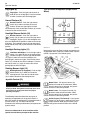
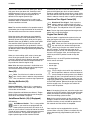
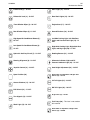
Horn (30) -10 AMP
Ground for Quick Coupler (34)
Electrical Monitoring System (31) - 15 AMP
Power for Quick Coupler (35)
Electrical Monitoring System (32) - 20 AMP
Crab Steering (36)
Reverse Backup Lights (37)
Circle Steer (38)
Frame Level (39)
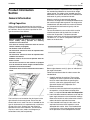
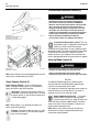
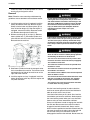
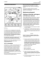
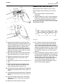
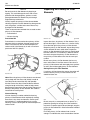
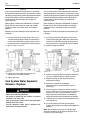
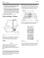
Illustration 270
g01056973
For Tier II machines, the fuse for the fuel pump is
located in the engine compartment next to the circuit
breakers. Remove the protective cover in order to
access the fuse.
Relays
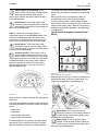
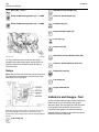
Ground for Auxiliary Diverter Valve (40)
Power for Auxiliary Diverter Valve (41)
Differential Lock (42)
Note: Your machine may not utilize all of the relays that
are listed here. You should only replace these relays
with relays of the same type.
Fuel Pump (43)
Engine Solenoid (44)
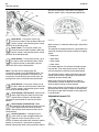
Indicators and Gauges - Test
Check for broken indicator lights, broken switches or
broken lenses on the instrument panel gauges.
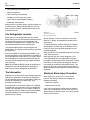
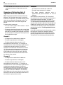
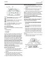
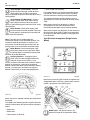
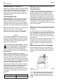
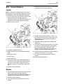
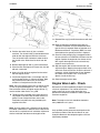
Illustration 271
g00951212
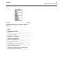
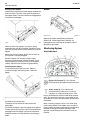
Illustration 271 shows the location of the relays on the fuse
panel. A pictograph is located on the access cover. The
location of the relay matches the location of the pictograph on
the film.
Fuel Pump (33)
Start the engine. Run the engine until the instrument
panel gauges have stabilized. Check that the
instrument panel gauges are operating correctly.
Stop the engine and perform any necessary repairs
before the machine is operated.