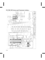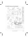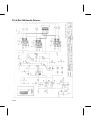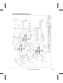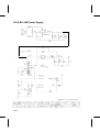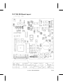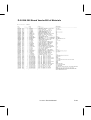
1
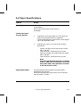
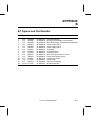
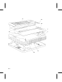
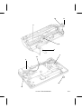
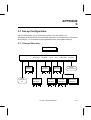
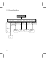
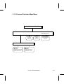
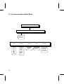
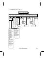
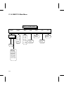
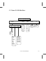
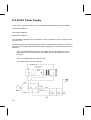
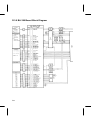
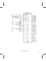
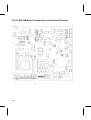
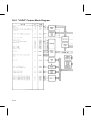
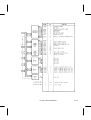
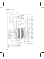
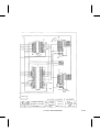
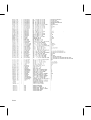
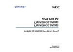
APPENDIX
A
A.1 Printer Specifications
Feature
Range
Printing Method:
Impact Dot Matrix, 9 pin
Protocols:
Digital's Conformance Level-2 (for sixel graphics)
IBM Proprinter III (4201/4202-III)
Epson FX-1050
Interfaces:
Serial,via 6 pin DECconnect type connector
Parallel, via 36 pin Centronics type connector
Selectable Baud Rates:
150, 300, 600, 1200, 2400, 4800, 9600
Selectable Data Bits
and Parity:
7-Even, 7-Odd, 7-Space, 7-Mark, 7-None
8-Even, 8-Odd, 8-None
Print Modes:
HSD, Draft, NLQ1/2
Quiet (double passes)
Average Print Speeds:
Print
Speed
HSD
Draft
NLQ1
NLQ2
300 CPS
240 CPS
55 CPS
55 CPS
Text Printing Pitches:
- Horizontal:
- Vertical:
from 5 cpi to 20 cpi
from 2 lpi to 12 lpi, and 1, 2, or 4 lines per centimeter
Graphic Resolutions:
- Horizontal:
- Vertical:
1/60", 1/72", 1/80", 1/90", 1/120", 1/144", 1/180", 1/240"
1/72", 1/144"
LA 310 - Service Manual
A-1
Feature
Range
Character Sets:
DEC PPL2
ASCII
DEC Supplemental
Dec VT100 Special Graphics
DEC Technical
ISO Latin-1 Supplemental
National Replacement Character (NCR) Sets:
British
Dec Finnish
French
Dec French/Canadian
German
Iso Italian
JIS Roman
DEC Norway/Denmark
ISO Spanish
DEC Swedish
Norway/Denmark
DEC Dutch
DEC Swiss
DEC Portuguese
Legal
DEC Hebrew Character Sets:
DEC 7-bit Hebrew
DEC 7-bit Hebrew Supplemental
ISO Latin Hebrew Supplemental
Greek Character Sets:
DEC Greek Supplemental
ISO Latin Greek Supplemental
Turkish Character Sets:
DEC 7-bit Turkish
DEC 8-bit Turkish Supplemental
ISO Latin-5 Supplemental
JIS Katana
A-2
Feature
Range
Character Sets:
IBM PP III and Epson FX
USA (Code Page 437)
Multilingual (Code Page 850)
Portugal (Code Page 860)
Norway (Code Page 865)
National Spain (Code Page 220)
Greece (Code Page 210)
Canada-French (Code Page 863)
Hebrew (Code Page 862)
Turkey (Code Page 857)
Input Buffer:
16K characters with down-loadable character set capabi
lity
32K characters with no down-loadable character set
capability
Serial Communications
Features:
Data flow control: Xon/Xoff or DTR
Disconnect on Fault: Drop DTR or Pulse DTR or Break
Dec PPL2 specifics: Auto answerback message,
Answerback on ENQ, Disconnect on EOT, Initialization
report
Optional Cards:
Character set cartridge
Font cartridge
Optional emulation
Resident Typestiles:
High Speed Draft
Draft Sans Serif
NLQ1 Sans Serif
NLQ2 Serifed
Print Attributes:
Underline
Double Underline
Overline
Italic
Strike-through
Shadow Bold
Double Width
LA 310 - Service Manual
A-3
Feature
Range
Dimensions:
Width= 605 mm,
Depth= 378 mm,
Height= 110 mm.
Weight:
10 kg
Power Requirements:
120 V @ 1.6 A, 50/60 Hz, 50 W
220 V @ 1.0 A, 50/60 Hz, 50 W
240 V @ 1.0 A, 50/60 Hz, 50 W
A-4
A.2 Paper Specifications
Feature
Range
Paper Types:
Pinfeed (tractor media)
Single sheets
Up to 4 part forms (with no pull tractor)
Envelopes
Continuous Paper
(Tractor Media):
1.
Single part continuous paper up to 16" (40.6 cm)
wide including perforations is supported.
The allowable weight for these forms is 56 to 90 g/m2
(15 to 24 pounds per ream).
2.
Multiple part forms: up to 16" wide including
perforation:
-
-
-
Single-sheet Paper:
4 parts (1 original and 3 copies) with carbon:
150 to 270 g/m2
Total thickness: .013"maximum (0.4 mm)
4 parts (1 original and 3 copies) without carbon:
130 to 220 g/m2
Total thickness: .013"maximum (0.4 mm)
Note
Hole spacing should be 12.7 mm +/- 0.25mm
(0.50" +/- 0.01") non accumulative over 50.8
mm (2.00") with a hole diameter of 3.8mm
to 4.1 mm (0.15" to 0.16").
Single-sheet plain bond, typewriter quality paper
between 60 and 100 g/m2.
Hand-fed multiple-part forms (0.013" max. thickness)
and up to 16.5" in width.
LA 310 - Service Manual
A-5
APPENDIX
B
B.1 Spares and Part Number
Ref. Pag. Seller's P/N DEC P/N
1
2
3
4
4
4
5
6
7
8
9
10
11
12
13
B-2
B-3
B-3
B-3
B-3
B-3
B-3
B-3
B-2
B-2
B-2
B-3
B-3
B-2
B-2/3
755800M
413414F
413413E
728795G
728796H
728797A
756412U
755812U
757113Z
758274T
758135G
757637E
757701P
758275U
757717E
29-30357-01
29-30358-01
29-30359-01
29-30361-01
29-30362-01
29-30360-01
29-30363-01
29-30364-01
29-30365-01
29-30367-01
29-30366-01
29-30370-01
29-30369-01
29-30368-01
29-30372-01
Description
Console Assembly
Mechanical Assembly (no Printhead)
Main Board (with Firmware and Interfaces)
Power Supply 220 V
Power Supply 240 V
Power Supply 115 V
Printhead
Printhead Cable
Console Overlay
Main Casing (includes SI cover)
Paper Guide Panel Group
Paper Select Lever
Platen Knob
Top Cover Assembly
Miscellaneous Kit
LA 310 - Service Manual
B-1
9
13
13
7
1
12
8
13
B-2
10
11
2
5
6
3
13
4
13
13
LA 310 - Service Manual
B-3
APPENDIX
C
C.1 Set-up Configuration
Set-up mode enables you to customize the printer for your specific use.
This appendix shows the structure of the Set-up menus, and can be used in conjunction
with Chapter 3. In the following figures,bolded items are the default settings.
C.1.1 Set-up Directory
Set-up Directory
PRINT
GENERAL
PROTOCOL
SELECTION
GENERAL
Main Menu
PRINT
Configuration
list
COMMUNICATIONS
COMMS
Main Menu
PROTOCOL
SELECTION
Main Menu
DEC
PPL2
IBM
PP III
OPTIONAL
EMULATION
IBM PP III
Main Menu
DEC
PPL2
Main Menu
LA 310 - Service Manual
EPSON
FX-1050
Main Menu
FACTORY
DEFAULT
Recall
Factory Defaults
CARD
EMULATION
Main Menu
C-1
C.1.2 General Main Menu
General Main Menu
Form
Length
Paper Print Typestyle NLQ
Backward
Auto
Width Quality
Direction Motion Advance
3"
3.5"
4"
5.5"
6"
7"
8"
8.5"
11" (A)
11 2/3" (A4)
12"
14"
15"
USER
Forced HSD
Forced NLQ!
Forced NLQ2
Soft/Control
Internal
Card Style 1
Card Style 2
1"-8"
8"
13.6"
C-2
Bidirectional
Unidirectional
Bottom
of form
Not Selected
Selected
Enabled
Disabled
0
1 inch
Input
Buffer
16 k
32 k
Error Paper
Beep Out
Selected
Not selected
1 Beep
3 Beeps
Continuous
Off
C.1.3 Protocol Selection Main Menu
Protocol Selection Main Menu
PORT- DEPENDENT
DEC PPL2
DEC PPL2
Protocol
Selected
SERIAL PORT
DEC PPL2
IBM PP III
EPSON FX-1050 OR
CARD EMULATION
IBM PP III
IBM PPP III
Protocol
Selected
EPSON FX-1050 OR
CARD EMULATION
EPSON FX-1050
or Card Emulation
Selected
PARALLEL PORT
DEC PPL2
IBM PP III
EPSON FX-1050 OR
CARD EMULATION
LA 310 - Service Manual
C-3
C.1.4 Communications Main Menu
Communications Main Menu
PORT SELECTION
SERIAL COMMUNICATIONS
Automatic
Serial Port
Parallel Port
C-4
BAUD
RATE
DATA
FORMAT
BUFFER
CONTROL
MONITOR
DSR
DISCONNECT
ON FAULT
150
300
600
1200
2400
4800
9600
7-Space
7-Mark
7-None
7-Even
7-Odd
8-None
8-Even
8-Odd
Xon/Xoff
DTR
Not selected
Selected
Not selected
Drop DTR
Pulse DTR
Break Signal
C.1.5 DEC PPL2 Main Menu
DEC PPL2 Main Menu
Character Horizontal Vertical Printer Disconnect Init.
Sets
Pitch
Pitch
ID
on EOT Report
GO User
Char Pref.
5
6
6.6
8.25
8.55
9
10
12
13.2
15
16.5
17.1
18
ASCII
British
French
DEC Finnish
DEC French-Can
German
ISO Italian
JIS Roman
DEC Norw/Dan
ISO Spanish
DEC Swedish
Norweg/Danish
DEC Dutch
DEC Swiss
DEC Portug
Legal
DEC 7 Hebrew
DEC Hebrew Sup.
DEC Greek Sup.
DEC 7 Turkish
DEC 8 Turkish
JIS Katana
DEC Supplement
DEC Spec Graph
Dec Thecnical
User Pref Set
.
.
.
cpi
cpi
cpi
cpi
cpi
cpi
cpi
cpi
cpi
cpi
cpi
cpi
cpi
2
3
4
6
8
12
1
2
4
lpi
lpi
lpi
lpi
lpi
lpi
lpcm
lpcm
lpcm
Auto Answerback Auto
LF
CR
Answerback on ENQ
Wrap on CR on LF
Not Selected
Selected
LA50
LA120
LA210
DEC PPL2
Not Selected
Selected
Not Selected
Selected
Not Selected
Selected
Not Selected
Selected
Not selected
Selected
Not Selected
Selected
DEC Supplement
ISO Latin-1
DEC 8 Turkish
ISO Lat-Hebrew
ISO Lat-Greek
DEC Greek Sup
ISO Latin-5
JIS Katana
DEC 7 Hebrew
DEC Hebrew Sup
Dec Thecnical
.
.
.
LA 310 - Service Manual
C-5
C.1.6 IBM PP III Main Menu
IBM PP III Main Menu
Character
Sets
C-Set National
1/2
Set
C-Set 1
C-Set 2
USA (437)
Multi (850)
Portug (860)
Norway (865)
Spain (220)
Greece (210)
Can-Fr (863)
Turkey (857)
Hebrew (862)
.
.
C-6
Horizontal
Pitch
5
cpi
6
cpi
8.55 cpi
10
cpi
12
cpi
17.1 cpi
Proport.
Prop. Enl.
Vertical
Pitch
2
3
4
6
8
72/7
1
2
4
lpi
lpi
lpi
lpi
lpi
lpi
lpcm
lpcm
lpcm
12 cpi
/Cond.
Slashed
0
LF
on CR
Normal 0
Slashed 0
12 cpi
20 cpi
CR
on LF
Not Selected
Selected
Not selected
Selected
C.1.7 Epson FX-1050 Main Menu
Epson FX-1050 Main Menu
Character
Sets
Graphic
/Italic
National
ASCII
Horizontal
Pitch
Code
Page
5
cpi
6
cpi
8.55 cpi
10
cpi
12
cpi
17.1 cpi
Proport.
Prop. Enl.
Vertical
Pitch
2
3
4
6
8
72/7
1
2
4
lpi
lpi
lpi
lpi
lpi
lpi
lpcm
lpcm
lpcm
Slashed
0
LF
on CR
Normal 0
Slashed 0
Not Selected
Selected
Graphic 1
Graphic 2
Italic 1
Italic 2
USA
France
Germany
U.K.
Denmark 1
Sweden
Italy
Spain 1
Japan
Norway
Denmark 2
Spain 2
Latin America
USA (437)
Multi (850)
Portug (860)
Norway (865)
Spain (220)
Greece (210)
Can-Fr (863)
Turkey (857)
Hebrew (862)
.
.
LA 310 - Service Manual
C-7
APPENDIX
D
D.1 General Block Diagram
MAINS
GROUP
SERIAL
INTERFACE
PARALLEL
INTERFACE
PRINT
GROUP
9 NEEDLES
PULL SPROCKET
SPROCKET PAPER
PRESENT
MICROSWITCH
BA 298 BOARD
PAPER
MOTOR
CARRIAGE
TRANSPORT
MOTOR
-
PAPER PRESENT
PHOTOSENSOR
CPU MPD 7810 MHz
CUSTOM "LOGO"
EPROM 128 KB
RAM 32 KB
E2PROM 256 BIT
STEP MOTOR DRIVER IC-200
NEEDLES DRIVER L6221
CARRIAGE RESET
PHOTOSENSOR
PAPER MODE
MICROSWITCH
(PLATEN -SPROCKET)
MEMORY
CARD
CONSOLE
COVER
OPEN
(DRY REED)
LA 310 - Service Manual
D-1
D.2 DC\AC Power Supply
The printer is set by the factory to be connected to the following nominal voltages:
120 V±10%, 50/60 Hz
220 V±10%, 50/60 Hz
240 V±10%, 50/60 Hz
The secondary voltage of the transformer is 29.5 V effective (±0.5 V) and the max.
current is 3 A.
The mains group is provided with a 630 mA fuse for the 220/240 V and with a 1.25 A fuse
for 120 V. The voltages generated by the power supplier (on the mother board) are the
following:
-
+35 V not stabilized for the motor and needle drivers (the motor circuit is
protected by a 1.6 A fuse (F3) and the needle circuit is protected by a 3.15 A
fuse (F2)).
-
+50 V not stabilized for the needle circuit
-
+5 V stabilized for the logic voltage.
MAINS GROUP
630 mA (220-240 V)
1.25 A (115 V)
J3
To page D-3
D-2
From page D-2
LA 310 - Service Manual
D-3
D.3 BA 298 Board
D.3.1 I/O Signal General Description
This diagram shows the functional blocks of the mother board BA 298 and the external
components interfacing the board. For each I/O signal of the board the following are
indicated: name, logic level, function, the connector abbreviation containing it and the
relevant pin.
The function and the level of the board internal signals are described in the specific
pages of the CPU MPD 7810 and “LOGO” custom. The signal direction is shown by the
arrows on the single lines.
Ther functional blocks of the board contain a function abbreviation (when the block
corresponds to an integrated circuit), a brief description of the function carried out and
a reference number of the schematics logic drawing.
Example: the block marked with the DR35 abbreviation identifies the diode rectifier
bridge shown in the 01 logic diagram.
The left hand side of the general diagram shows the connectors interfacing the mains
group, the optional memory card, the optional serial and parallel interface and the
console.
The right side shows the connectors interfacing the drivers and the signal devices of the
printer.
Board BA 298 is divided into the following functional blocks:
D.3.2 CPU and EPROM-SRAM-E2PROM Memories
The CPU operates with a basic firmware contained in a single 64 Kbyte EPROM. This
firmware emulates the IBM Proprinter III and EPSON FX1050 printers.
The memory card may also contain an additional emulation or an extension of the
character generator. In any case , the emulation or the additional character set can be
used alternately.
The SRAM has a capacity of 32 Kbytes and can be expanded with the memory card.
The E2PROM contains 256 bits (16x16) at sequential access which can be cancelled or
rewritten with the set-up procedure of the printer parameters.
D-4
D.3.3 “LOGO” Custom
It groups most of the I/O printer functions. The interface signals and the custom
functional blocks are shown in pages 1-5 and 1-9.
D.3.4 Needle Drive Circuit
It includes the needle command storage circuit DKHO, the darlington switches KQ22
and the needle fire timing logic. The firing configuration is caused by signals DAD007 and AGO09 for the ninth needle.
The needle power circuit is protected by fuse PF8N which interrupts the +35 V when the
printhead is overheated.
The max. supply voltage is 2.2 A.
D.3.5 Paper and Carriage Motor Drive Circuit
The power circuit is based on components CMA7. The motor phase signals are generated
by the “LOGO” custom whilst the motor phase timing is referred to the CPU.
D.3.6 Console LED Drive Circuit
The console LEDs are driven by the display driver DD04.
D.3.7 Reverse Channel, CTS, RTS Signal Storing Circuit
This circuit, formed by F/F DHT4 and and/or ports, activates the drive signals of the
serial interface in output from the printer.
D.3.8 Console Signals, Sensors and Microswitches
These signals are asynchronous with respect to the CPU events and therefore are
handled by the interrupt logic. The interrupts are generated for paper end signal, carriage reset and console key command.
LA 310 - Service Manual
D-5
D.3.9 BA 298 Board Block Diagram
D-6
LA 310 - Service Manual
D-7
D.3.10 BA 298 Board Component Location and Function
D-8
Connectors
J1
J2
J3
J4
J5
J6
J7
J8
J9
J12
J13
Serial Interface
Centronics Interface
AC Mains
Memory Card
Paper on platen photosensor
Paper on sprocket microswitch
Console
Carriage reset photosensor
Paper motor
Printhead needles
Carriage motor
Components
DR1
F2
F3
US1
US2
US3
US4
US5
US6, US7
US8
US10
U1
U2
U3
U4
U5, U7, U10
U6, U8, U9
SW1
S1
Rectifier Bridge
3.15 A Fuse
1.6 A Fuse
Custom LOGO SPLCC
EPROM 1 Kbit
4D Flip Flop
Display Driver
Traspar. Latch
RAM 32 K
LM339 Voltage Comparator
78C10 CPU
IC87 Power Switch Regulator
Powered Dual RS-232 TX-RX
Differential Line Receiver
Display Driver
Needle Darlington
Step Motor Driver
Paper Feeding Selection Switch
Firmware EPROM
LA 310 - Service Manual
D-9
D.4 “LOGO” Custom (84 PINS)
This custom concentrates in a single chip the main I/O and interface functions of the
LA310 MultiPrinter.
The custom basic timing is the same used by the CPU and the data exchange between
CPU and printer is carried out by the data bus and the address bus.
The functions of the custom are the following:
-
Testing the Memory Card insertion.
This function is performed by signals M-PRMCO-SECU1 which make a loop
among pins 2, 1, 59 and 60 of the Memory Card when the latter is correctly
inserted in the mother board connector.
The ground signal applied to pin 2 passes through the loop and brings signal
SECU1 low.
If the Memory Card is wronly inserted the reset signal RESSA is generated.
-
Baud Rate generation.
It generates the transmission clock for the serial interface data. Signal TXCLK
should have a different frequency depending on the line speed (150-9600 bps).
-
Address bus decoding.
The decoding of signals ADR13, 14, 15 selects the logic groups internal to the
custom.
-
Data bus decoding.
This function is enabled by signal ALEAA (Address Latch Enable) and supplies
the least significant address bus.
-
Handling the console local status.
When the local key is pressed and the printer is on line, signals CSLED (chip select
of the console) and LED09 (Local LED switch on) are generated.
-
Timing of the E2PROM serial signals.
It generates signals CSEEP (E2PROM chip select) and CKEEP (serialization
clock of E2PROM I/O data).
D-10
-
3 motor phase signal generation (paper).
It scans the sequence of FASA3, B3, C3, D3 signals which cause the clockwise/
counter-clockwise motion of the step motor.
-
DC motor driving.
Not used on LA 310.
-
2 motor phase signal generation (carriage transport).
It scans the sequence of FASA2, B2, C2, D2 signals which cause the clockwise/
counter-clockwise motion of the step motor.
-
1 motor phase signal generation.
Not used on LA 310.
-
EPROM-RAM memory addressing.
It generates signals CSEP1-CSEM1 (chip select of the basic EPROM and of the
EPROM on the Memory Card), CSRA1-CSRM1 (chip select of the basic RAM and
of the Memory Card of the RAM), APA13, 14, 15 (memory page address).
-
Italic, Double height, Superscripts, Subscripts character generation.
These types of printing are activated by means of special commands sent by the
system.
-
Parallel Interface signal handling.
It transfers the character present on bus DACE0-7 each time it receives the ready
character strobe STROB. It signals to the system the character received status
and the conditions of printer busy, paper end, malfunction and printer selected.
LA 310 - Service Manual
D-11
D.4.1 "LOGO" Custom Block Diagram
D-12
LA 310 - Service Manual
D-13
D.5 Schematics
D.5.1 BA 298 Logic and Memory
D-14
LA 310 - Service Manual
D-15
D.5.2 BA 298 Custom and Centronics Interface
D-16
D.5.3 BA 298 Console and Serial Interface
LA 310 - Service Manual
D-17
D.5.4 BA 298 Needle Drivers
D-18
D.5.5 BA 298 Motor Drivers
LA 310 - Service Manual
D-19
D.5.6 BA 298 Power Supply
D-20
D.5.7 BA 298 Board Layout
LA 310 - Service Manual
D-21
D-22
D.5.8 BA 298 Board Vendor Bill of Materials
LA 310 - Service Manual
D-23
D-24