1
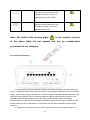
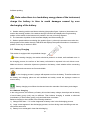
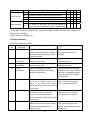
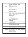
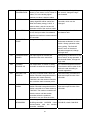
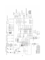
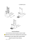
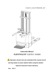
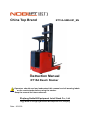
China Top Brand
RT15A-SMS-001_EN
Instruction Manual
RT15A Reach Stacker
Operators should read and understand this manual and all warning labels
on the reach stacker before using the stacker.
Keep the manual for future reference.
Zhejiang Noblelift Equipment Joint Stock Co., Ltd
Jingyi Road of Changxing Economic Development Zone, Zhejiang
Date:2012.03
Table of Contents
INTRODUCTION ..................................................................................................1
1
GUIDELINES FOR SAFE OPERATION....................................................2
2
TECHNICAL MANUAL .................................................................................5
3
TRANSPORT AND TRIAL RUN .................................................................9
4
DRIVING MANUAL ..................................................................................... 11
5
MAINTENANCE, RECHARGING AND REPLACEMENT OF THE
ACCUMULATOR................................................................................................16
6
MAINTENANCE AND SERVICE MANUAL ............................................23
Introduction
Welcome to use this series of reach stackers. This manual gives clear information on how to
master safe operation of the reach stackers.
The differences between various reach stackers are described in detail in this manual. During
operation and maintenance, please refer to the contents corresponding to the reach stacker types
you are using.
The safety instructions and important precautions are indicated with the following icons:
1.
---- This icon indicates the existence of a hazard that could result in personal injury if
the safety instruction is not observed.
2.
---- This icon indicates that a failure to observe the described instruction could lead to
equipment damage.
3.
---- This icon refers to general notes and instructions before use.
Most parts of the product are made from recyclable steel. The recycling and disposal of
cast-offs resulted during use, maintenance, cleaning and disassembling the product has to comply
with local regulations without pollution to the environment. The recycling and disposal of the
cast-offs should only be operated by specialised personnel in the designated area. The cast-offs
such as hydraulic oil, batteries and electronic units, if improperly disposed, may be hazardous to the
environment and human health.
Due to continuous product improvement, Noblelift reserves the right to make changes in
product designs and specifications without prior notice. For the latest product parameters, please
feel free to contact us. Note: All parameters provided herein are as of the publication date of the
Instruction Manual.
1
1
Guidelines for Safe Operation
1.1 Requirements for the driver: The stacker should only be operated by personnel trained in
operating the stacker.
1.2 The right, duty and responsibility of driver: Clear with his own right and duty, the driver
should be trained in operating the stacker and also knows the contents in this operation manual
very well.
1.3 Unauthorized persons are prohibited to use: The driver is responsible for managing the
stacker in use, and must prevent any unauthorized person from driving or operating the stacker.
It’s prohibited to transfer and raise the person by the stacker.
1.4 Malfunction and Defects: In case malfunction or defects occurs with the stacker, the driver
should immediately inform the supervisor. If the stacker can not be operated safely, e.g. with
worn wheels and brake malfunction, always stop using it until repaired completely.
1.5 Repair:The driver is not allowed to make any repair or change without professional training
and clear authorization. The operator is not allowed to change the position of switch, safety
devices and so on or make them invalid.
All original spare parts from the factory are strictly verified by Quality Assurance Department.
Only use spare parts from the manufacturer for the guarantee of the safety
and reliability of stacker operation. The replaced material such as oil or fuel should be collected
and disposed of according to local environment protection and health regulations.
1.6 Dangerous area: Dangerous area generally refers to these locations, in which reach stacker
or its lifting mechanism (e.g. fork or accessories) is moving, lifting or lowering, thus being
dangerous to persons in this area, or in which the stacker is handling loads. Generally the
scope of this area extends to locations to which the loads or accessories on the stacker is
lowered.
Unauthorized persons must be ordered to leave dangerous areas. The driver should
always give warning if there is any risk of human injury. If the warned persons still stay in
dangerous area, the driver should stop the stacker immediately.
1.7 High-risk environment: when working in high risk environments the truck must be equipped
with specialized safety device. As working in oil depot, the truck should be equipped with
anti-static devices.
Ordinary truck usually is not equipped with these devices
1.8 Safety devices and warning signs:Sufficient attention should be paid to safety devices,
warning signs and precautions described in above sections in this manual.
2
1.9 Driving in public places: The stacker is prohibited to drive in public places except for special
areas.
1.10 Space between vehicles: Remember to keep a proper distance from the vehicle ahead,
since it may stop suddenly at any moment.
1.11 Passengers: Never carry or lift person with this stacker.
1.12 Headroom: Never use the stacker in areas where the headroom is lower than the height of
overhead guard or mast or loads.
1.13 Operation in a lift or loading platform: If the load capacity of the lift or platform is sufficient
and the space is enough for stacker operation, they can be used for transportation with the
permission from the stacker user. The stacker must be confirmed by its driver himself before
entering the lift or loading platform. When entering the lift, the loads must enter ahead. And
locate the stacker in a suitable position to prevent from contacting walls around. If passengers
take the lift together with the stacker, they have to enter after the stacker enters and stops firmly,
and leave before the stacker.
When calculating the weight, it must be the sum total of goods and light weight.
1.14 Driving passageway and working area: The stacker must be driven in designated
passageway. Non-related persons must leave the working area. Loads must be stacked in
designated locations.
1.15 Operation Management: Driving speeds must be suitable to local conditions. Always drive in
lower speed when passing curved passageways, narrow passageways, sight blind spot or
rotary doors or any obstructed places. It is prohibited to make an abrupt stop (unless in
emergency), rapid U-turn and chase with each other in sight blind spot or obstructed places.
Never operate the stacker with the body stretching out of it.
1.16 Visibility: The driver must keep his eyes on moving direction and have a clear view of the
road ahead. In case the loads carried block sight of the driver, the stacker has to be driven
reversely. If this is not practical, another person should walk in front of the stacker, giving
corresponding guidance and warning to the driver.
1.17 Passing a ramp: Only known ramps are permitted to pass. And the ramps must be clean,
anti-skid and meet specification requirements of the stacker. Loads on the fork must face the
downward slope. Never turn around, drive obliquely or stop on a slope. Pass a ramp in lower
speed and get ready for braking at any time.
1.18 Load capacity of the floor: Check if the load capacity of the floor suit for the driving of the
stacker .
1.19 Transportation: The fork should be kept lower than 300mm from the floor during
non-transportation driving. It is better to driver in reverse direction of the fork to get good vision
and mobility. Driving with the fork forward may cause unpredictable mobility problems.
3
1.20 Features of load: The carried goods must be safe and reliable. The height of carried goods
should not exceed the height of the fork carrier or backrest.
1.21 Driving on loading platform or approach bridge: Before driving the stacker onto loading
platform or approach bridge of a truck, make sure to check the max. load capacity of the
approach bridge and if it is equipped with anti-sliding devices. The driver must also check the
max. load capacity of the truck or platform and if there are devices such as brake cushion block
to prevent the truck or platform from moving.
1.22 Safe Parking: The stacker should be parked in a designated specialized parking area. The
parking place should be horizontal and firm. If the stacker is equipped with parking brake device,
start this device when parking. Pay attention to safety when parking the stacker. Never park the
stacker on a slope or on a ramp. The fork must be lowered down to the lowest position after
parking to avoid accident because of sudden lowering. Turn the electric lock to “OFF” position to
prevent unauthorized operation. In order to avoid unauthorized personel to use this stacker, the
operator should remove the switch key when leaving the position.
If the truck will not in use for a period after parking. Such as off work, and does not need to
charge, the battery plug should be unplugged.
1.23 Signalling: Warning signals can be sent by the horn on the stacker to catch people’s
attention.
1.24 Protection shoes: According to EU standard EN-345:1-S1, standard protective shoes must
be worn when operating the stacker.
1.25 Truck modification: No modifications or alterations to a powered industrial truck, which
may affect, for example, capacity, stability or safety requirements of the truck, shall be made
without the prior written approval of the original truck manufacturer, its authorized
representative, or a successor thereof. When the manufacturer or its successor approve a
modification or alteration, they shall also make and approve appropriate changes to capacity
plate, decals, tags and operation and maintenance handbooks.
Only in the event that the truck manufacturer is no longer in business and there is no
successor in the interest to the business, the user may arrange for a modification or alteration to
a powered industrial truck, provided, however, that the user shall:
a) arrange a industrial truck and its safety expert to design, test and complete the
modification or alteration;
b) maintain a permanent record of the design, test(s) and implementation of the
modification or alteration;
c) approve and make appropriate changes to the rated capacity plate(s), decals, tags and
instruction handbook;
d) affix a permanent and readily visible label to the truck stating the manner in which the
truck has been modified or altered together with the date of the modification or alteration, and
the name and address of the organisation that accomplished the tasks.
Failure to comply with these instructions will invalidate the guarantee. The guarantee is
also invalidated if the stackers are exported by the customer (or a third party) illegally without
the consent of Noblelift.
4
2
Technical Manual
RT15A series of reach stacker are designed for short and medium distance high-strength
transportation on flat road surface, the max. load capacity can reach 1500kg.
2.1
2.1.1
Technical feature
Load capacity under different heights and different load centers
Lifting height h3 mm
3000
3300
3500
4000
4500
5000
5300
6000
7000
8000
Load center distance ( C )
mm
Actual load capacity ( Q ) kg
1500
1200
1500
1200
1500
1200
1500
1200
1500
1200
1500
1200
1500
1200
1200
900
1000
800
800
600
500
600
2.1.2 Mast parameter
Item
Dual mast
Triple mast
Enclosed mast height
h1 mm
Lift height
h3 mm
2100
2250
2350
2600
2850
2230
2400
2565
2730
3065
3400
3000
3300
3500
4000
4500
4500
5000
5500
6000
7000
8000
5
Extended mast
height
h4 mm
3865
4165
4365
4865
5365
5365
5865
6365
6865
7865
8865
2.1.3 Structure
6
Other
Electric motor
Performance
Dimensions
Wheel types
Weight
Characteristics
RT15-A Technical data
1.1
1.2
1.4
1.5
1.6
1.7
Manufacturer`s type designation
Drive (battery, diesel, petrol, natural gas,electric)
Operator type ((hand, pedestrian, stand-on, sit-down,
order-picker)
Rated load capacity
Load centre distance
Distance between fork backrest and front wheel
Wheelbase
2.1
Service weight(including battery)
3.1
3.2
3.3
3.4
3.6
3.7
4.1
4.2
4.3
4.4
4.5
4.6
4.7
4.8
4.9
4.10
4.11
4.12
4.13
4.14
4.15
4.16
4.17
5.1
Tyres (rubber, high-elastomer, pneumatic, polyurethane)
Tyre size
driving wheel
Tyre size
load wheel
Caster wheel (dimensions)
Wheels, number front/rear (x=driven wheels)
caster/load
wheel
Tread, front
Tread, rear
Lowered mast height
Free lift height
Lift height
Extended mast height
Height of overhead guard of driving
Height of stand board
Height of steering wheel
Lowest height of fork
Overall length
L ength between fork backrest and vehicle body
Overall width
Fork dimensions
Fork carriage width
Overall fork width
Ground clearance
Aisle width for pallets 800x1000 lengthways
Turning radius
Drive speed, laden/ unladen
5.2
5.3
5.4
Gradebility, laden/ unladen
5.5
6.1
6.2
6.3
6.4
6.5
6.6
7.1
7.2
Serivice brake
Drive motor
Lifting motor
Battery acc.to DIN 43531/35/36 A, B, C, no
Battery voltage, nominal capacity K5
Battery weight
Battery dimensions l /w / h
Type of drive control
Noise level at operator’s ears
1.3
3.5
RT15A
electric
Stand-on
Q
C
X
y
kg
mm
mm
mm
1500
500
180
1482
kg
3500(lifting 5300)
mm
mm
mm
polyurethane
Φ343×140
Φ267×106
Φ180×70
1x 2 / 2
b10
b11
h1
h2
h3
h4
h6
h7
h14
h13
l1
l2
b1
s/e/l
b3
b5
m1
Ast
Wa
mm
mm
mm
mm
mm
mm
mm
mm
mm
mm
mm
mm
mm
mm
mm
mm
mm
mm
mm
km / h
660
1010
See mast table
See mast table
See mast table
See mast table
2330
350
1320
35
1855
1325
1130
35 / 100 / 920
760
760
80
2700
1748
9.5 / 9.5
Lift speed, laden/ unladen
mm/s
280 / 310
Lowering speed, laden/ unladen
mm/s
350/ 320
%
kw
kw
V/Ah
kg
mm
dB
7
10 / 15
electromagnetic
5.5
8.6
43531 B
48 / 360
660
1020 / 412/ 540
MOSFET Control, AC
<70
This table is made according to regulation VDI 2198 , only provides with the technical data
of standard stackers. Technical data of non-standard stackers and trucks with accessories or other
optionals are different from the table above. We reserve the right to update technical data of this
stacker.
48V/360Ah battery is optional, the battery is in accordance with DIN standard, the battery
compartment dimension l/w/h is: 1020/ 412/ 500 mm.
2.2
Technical Standards
Continuous noise level should be less than 70dB(A) according to ISO4871 standard.
Continuous noise level is an average value of noise measured at the driver’s ear during
travelling, lifting and being standby.
Electromagnetic Compatibility (EMC)
The manufacturer confirms that the stacker complies with EN12895 and other relevant standards
on limits of electromagnet radiation and interference, and has been tested on static discharge.
Never modify any part of electrical system without written permission from the
manufacturer.
2.3 Operation Conditions
Ambient temperature: 5℃~40℃
Special devices have to be used under a temperature below 5℃ or in very humid
environment,
Altitude: up to 2000m.
If there is a quality problem or need to order spare parts, please indicate the serial number
of the stacker and parts number.
8
3
Transport and Trial Run
3.1 Transport with A Crane
Load capacity of the crane in use must be sufficient (larger than the net weight of stacker;
see the nameplate on the stacker).
The hook holes are specially designed for convenient transportation of the stacker.
— Park the stacker in a safe position.
— Hooks of the crane must be applied at hook holes.
Hooks of the crane must be applied at hook holes, ensuring the stacker will not be slipped
down.
3.2 Trial Run
The stacker can only use accumulator as power supply. Changing to use AC power will
damage the electric circuit. Cables connecting the accumulator should be less than six meters.
To ensure the normal work of the stacker after delivery or transportation, the following
operations have to be completed:
— Check the completeness of the stacker and devices.
— If necessary, install batteries without damaging the connection cable.
— Recharge the accumulator immediately.
— If customers want to replace the accumulator with a maintenance-free one, make sure
that the new accumulator matches the accumulator coulombmeter (or is permitted by
service technician of the manufacturer).
3.3 Towing of Stackers without Driving Ability
When towing the stacker without driving ability, release electromagnetic brake before moving.
— Press emergency control button and turn the power supply switch to “OFF” position.
— Open the cover of electric unit.
— Release 3 screws counter clockwise on the electromagnetic brake until the brake does
not impede the stacker from moving.
Now, you can tow the stacker.
After arriving at the destination location, recover the stacker to original status.
9
3.4
Assembling
Sometimes, in order to transport conveniently, the mast assemblies are apart. Now, you need to
assemble according to the following steps. Some tools are needed, such as hoisting equipment,
wrench, etc.
3.4.1 Hoist the mast assemblies together with hoisting equipment.
3.4.2 Fix the mast to the forward frame with two high-strength bolts. Don't forget to assemble
washers and spring washers.
3.4.3 Adjust the washer number to make the mast vertical to the ground.
3.4.4 Tighten two bolts.
3.4.5 Connect the oil tube.
10
4
Driving Manual
Steering: 180° electric seamless steering, the steering motor will stop automatically when swerving
to +90° which eliminates any chance of overload.
Driving: 5.5 kW drive motor with powerful driving and convenient acceleration. Helical gears
technology of transmission case makes the driving more efficient and energy saving.
Hydraulic system: 8.6 kW hoisting motor is efficient and powerful. Sensitive hand control valve
allows lowering or lifting speed and height control at will.
Brakes: Equipped with two independent braking systems. Regenerative braking, when the operator
loosen the speed controller or turn the controller reversely, the motor will run automatically under a
generator state so as to realize flexible brake to protect the brake block of the electromagnetic
brake and realize energy recovery. Another way of braking is electromagnetic brake, which is only
used as a service brake and emergency brake.
Three-phase AC technology: The driving motor and steering motor are both use the three-phase
AC technology. Compared with traditional DC motor, the motor speed can be regulated smoothly
with a wide speed range and high efficiency. Avoiding the trouble of replacing motor carbon brush
which relatively realize the maintenance-free of the motor.
4.1 Stacker Appearance and Operation Board Introduction
1 Headlight
2 Display
3 Foot switch
11
11 Horn Button
9 Headlight Switch
8 Key Switch
7 Instrument
6 Emergency Stop Switch
12 Safe Handrail
10 Steering Wheel
1
Headlight
2
Display
3
Foot Switch
4
Speed Controller(accelerator)
5
Control Handle(including lifting and lowering control handle、forward/tilting/sidesway control
5 Control Handle
4 Accelerator
handle)
6
Emergency Stop Switch
7
Instrument(shows turning angles of the driving wheel、residual energy、current real-time
speed)
8
Power Key Switch
9
Headlight Switch
10 Steering Wheel
11 Horn Button
12 Safe Handrail
12
4.2 Safety features of the stacker
The stacker is equipped with adequate safety device to decrease the occurrence of the accidents.
A 、When the forks are lifted to 400m
and lead magnet steel to go through the
surface of magnetic control switch, the
driving speed decreases immediately to
achieve steady driving and safe
operation; when magnet steel lowers
with the forks and go through magnetic
control switch again, the driving speed
recovers. By controlling the fluctuating
range of lifting and lowering control
handle, it can certainly control the lifting
and lowering speed.
Speed
Limit
Switch
Magnet
Steel
Limit Switch
The function of this speed limit switch is
the same as that of the magnetic control
switch in the above picture: making the lifting
speed reduce when the forks are lifted to a
certain height. Limit switch is on the top, the
function is forks can not rise when they are
lifted to the highest point and reach the
limited lifting height to meet safety operation
requirement.
Speed Limit
Switch
B、Move the steering wheel to forward the driving wheel in straight line, the driving speed can reach
full speed, when the steering wheel turns for a certain angle, it makes the driving wheel turn a
certain angle accordingly to achieve turning effect. In turning process, when driving with the turning
angle exceed +20° from the straight line, the speed will decrease accordingly with the different
turning degrees, larger turning angle, slower speed in order to achieve stable turning and safe
driving.
13
C、 Turn on the power, the system starts self checking, when the electric system has fault, like open
circuit, short circuit or the control button is in active state, such as stepping on the foot switch firstly,
the speed controller is not in neutral position and so on, the stacker will not work and alarm fault,
then only after trouble shooting of the electric system, the stacker can continue to work.
D、Operation steps of normal driving:
open the emergency stop switch and
key switch firstly, and check whether
the acceleration handle is in neutral
position, it is effective only in neutral
position, then step on the foot switch,
operate the acceleration handle to
drive forward and backward, otherwise
the instrument will alarm the following
fault:
ALARM
79
ON NODE 2
While driving, if you loose the foot
switch suddenly, the stacker will brake
and stop immediately (the accelerator
is not in neutral position now), and the
instrument alarms fault, only after the
acceleration handle turns back to
neutral position, the fault will be
eliminated, continue the following operations to avoid misoperation and keep the stacker safer.
E、When the battery energy drops to 20%, the instrument
flashes, and flashes the fault code
"66"on the instrument prompting to perform recharging and lock the lifting function to limit the lifting
function of the forks, the stacker now can only drive rather than lifting to avoid safety accidents
caused by insufficient energy while lifting, and ensure personal safety, the function recovers after it
is fully charged.
The truck is equipped with full safety device to minimize the occurrence of accidents.
A) When the fork height exceeds 1000 mm, the drive speed will automatically reduce.
B) When the steering angle is over ±20°, the drive speed will automatically reduce.
C) When the electrical system has faults, the truck will automatically stop.
D) The truck can only drive after stepping on the pedal switch.
E) Before electrifying ( the power key switch turn to “ON” position), if any control button is active,
such as stepping on the pedal switch, the speed controller is not in the neutral position, etc., the
truck will not drive.
F)
If the controller temperature is over 75 ℃, the maximum current will reduce proportional with
the increasing of the temperature. The temperature of the controller should not exceed 100 ℃.
14
G) The protection level of the controller is IP54 which can prevent dust invasion and liquid splash.
H) When battery power is too low, the maximum current will reduce to half of the maximum
current.
4.3
Driving of the stacker
Before driving or handling the goods, the operator must ensure that all personnel leave
the dangerous zone.
A) Turn the key switch to “ON” position when entering the cab.
Before electrifying ( key switch turn to “ON” position), if any control button is in active. The
security feature will automatically lock the truck after electrifying,.
B) Hold the handle of the steering wheel with left hand and grip the speed controller with right
hand.
C) Step on the pedal switch with left foot to loosen the electromagnetic brake and keep stepping in
the process of driving.
D) When moving the speed controller forward or backward, the truck will move forward or
backward accordingly. The controller moves larger, the drive speed and acceleration are faster.
Acceleration and deceleration of the truck should be gentle, do not accelerate or decelerate
suddenly.
When driving on the slopes, loads on the fork must face the uphill.
E) Three braking methods are available:
-
Brake the truck by reducing the speed potentiometer input or turning the speed
potentiometer to the neutral position. This braking method is soft and stable,and should be
often used.
-
Reverse braking, for example,
change the driving direction, i.e. move the speed
potentiometer in reverse direction. The more the speed potentiometer moved, the faster
the brake works.
-
Put the speed controller in the neutral position first, then release the pedal switch to brake.
This method can only be used for emergency braking.
Driving in the opposite direction of the fork as much as possible to have a good view and
maneuverability.
15
5 Maintenance, Recharging and Replacement of the
Accumulator
5.1 Safety Operation Procedures for Lead-acid Accumulator
The stacker must be parked in a safe location before any operation is performed on the
accumulator.
5.1.1 Maintenance Technician
Only qualified technician can perform operations on the accumulator such as recharging,
maintenance and replacing. Before operation, carefully read instruction manuals including
operation manual, replenishment preparation and recharging requirements.
5.1.2 Fire Prevention Measures
Smoke or open fire is forbidden when operating the accumulator. The accumulator should be
away from inflammable materials for at least two meters when storage or recharging. The
accumulator storage place should be well ventilated and equipped with fire fighting devices.
5.1.3 Maintenance of the Accumulator
1) Keep the nuts on every battery cell dry and clean. Tighten every terminal and cable end and
brush them with grease to prevent corrosion. Bared terminals and terminal posts should be
covered with an antiskid insulating cover.
2) The cable lines of every two cells should be well-connected. Check the nuts on each pole for
loosen or sliding, if happens, tighten the nuts.
3) Keep the surface of accumulator clean and dry. After completing recharging, clean the spilled
acid with cotton yarns or brush, and clean with wet towel if necessary.
4)Avoid over recharging and over discharging, and fast charging and insufficient recharging are
also not allowed. Otherwise the life span of the accumulator may be affected.
5) It is forbidden to put conductive objects (including metal tools) on the accumulator, or short circuit
even explosion may be caused.
6) Never spill any harmful liquid or solid materials on surface of the accumulator. When using a
densimeter or a thermometer, make sure the surface is clean and clear.
7) Recharge the discharged accumulator in time. Delayed recharging may damage the accumulator.
Do not delay recharging for more than 24 hours. The outdoor accumulator may not easy to
charge In cold weather,. In this case, move it indoors to charge.
16
8) If the accumulator won’t be in use for a long time, it should be recharged once every month and
fully charged every time.
9) When charging or using, the battery must be supplied with distilled water regularly because of
evaporation, you have better check the battery electrolyte weekly, the liquid level must be kept
between the highest liquid level and the lowest liquid level of the battery.
The supply condition and filling amount of the distilled water are as follows:
Battery
cover
Note:When the electrolyte liquid level is not enough, do not supply acid blindly (test the
specific gravity after fully charged), the battery supply must be distilled water.
10)
When several battery cells have fault, you should find out fault causes and fault cells
immediately and repair. If can not be repaired, change them, monitor vitriol proporation of each
cell of the battery with gravitometer regularly (H2SO4 proporation1.27-1.29, fully charged).
Gravito
meter
17
11) Make sure the ambient environment is well-ventilated while charging, flammable gas (H2O
=H2↑+O2↑)may be produced during the battery charging process, prohibit smoking and open
fire at site to avoid risk of hydrogen explosion.
12) The electrolyte in the accumulator is toxic and corrosive. For this reason, always wear working
clothes and protective glasses to keep your body away from the electrolyte in accumulator
under any operation condition.
13) If your clothes, skin or eyes touch acid liquid in accumulator, wash with large amount of clean
water. When your skin or eyes touch acid liquid, wash with large amount of clean water and
also seek doctor’s treatment immediately. The spilled acid must be neutralized and treated
immediately.
14) The weight and dimension of the accumulator have a considerable effect on the stability of the
stacker. Therefore do not modify the type of accumulator without the approval of the
manufacturer.
15) Never discharge in large current, for example, performs driving and lifting simultaneously.
5.1.4 Disposition of Worn-out Accumulators
Scrapped accumulators should be recycled and stored in specified environment protection
areas or cast-off treatment zones according to local laws and regulations. These works should be
done by qualified specialized companies.
5.2 Specification of the Accumulator
Weight and dimension can be found on the nameplate of the accumulator.
Uninsulated terminal poles on the accumulator should be protected with an insulated cover.
When connecting the accumulator with the socket, make sure the stacker is powered off and the
switch is at “0” position. When replacing or assembling the accumulator, make sure the
accumulator is fixed securely in battery box.
5.3 Storage, Transportation and Installation of the Accumulator
The stacker should be parked on the level ground steadily. To avoid short circuit, the bared cable
ends and terminal posts should be covered with insulated covers. When the accumulator is pulled
out, arrange the connectors and cables of removed accumulator properly without blocking access
18
of the accumulator.
When handling the accumulator with a crane, make sure the load capacity is sufficient (the
weight of the accumulator is marked on both the nameplates of the accumulator and the stacker).
The hoisting device must be pulled vertically to avoid the damage of the accumulator box. The
hooks of the hoisting device should be safe and secure. Never let the hooks fall onto a single
battery .
—Press emergency stop switch and turn the power switch to “OFF” position.
—Step on the battery protection device to release the lock state of the accumulator box.
—Remove the connectors of accumulator cables.
—Connect the lifting device to hook holes.
—pull the accumulator out by side and move it away with handling equipment.
5.4
Instrument Indicator
SMART—DISPLAY is an intelligent instrument based on CAN BUS, the instrument can monitor the
electric system through real-time monitoring the performance of the whole truck by the bus.
1) Monitor the battery energy, when the battery energy decreases, the instrument will
continuously extinguish the LED backlight with a particular algorithm to indicate the residual energy
of the battery in order to check the energy.
2) Because the SMART—DISPLAY is a kind of intelligent instruments based on CAN-BUS, it
can share data with the controller. The instrument can also indicate the information of the truck in
the driving state, such as the angle of guide wheel and driving speed at the same time.
3) Monitor the entire bus system, when there is a failure in the bus node point, the instrument
will display in the form of fault code, and the stacker will stop working at the same time until
troubleshooting.
19
Instrument Overview
Buttons and Figures Description
Figure
Figures and
button names
Using methods and functions
System
self-check lamp
The light shines once when opening the
key and system conducts self checking .
Failure warning
light
The trouble light flashes indicating that
there is a fault of the stacker.
Battery energy
warning light
Energy warning light flashes indicating
that battery energy has run out.
Brake oil supply
warning light
Brake oil supply warning light
This function is
effective when
using mechanical
brake.
Brake light
Hand brake the warning light.
This function is
effective when
using mechanical
brake.
Safety warning
light
Seat safety switch warning light.
This function is
effective when
using seat safety
switch.
Number key
When the instrument is used as a
real-time control instrument of the
CAN-BUS network, this key is a
keyboard button: ENTER
Number key
When the instrument is used as a
real-time control instrument of the
CAN-BUS network, this key is a
keyboard button: ROLL UP
Number key
When the instrument is used as a
real-time control instrument of the
CAN-BUS network, this key is a
keyboard button: ROLL DOW
Number key
When the instrument is used as a
real-time control instrument of the
CAN-BUS network, this key is a
keyboard button: SET UP
20
Remarks
Number key
When the instrument is used as a
real-time control instrument of the
CAN-BUS network, this key is a
keyboard button: SET DOWN
Number key
When the instrument is used as a
real-time control instrument of the
CAN-BUS network, this key is a
keyboard button: OUT
Note: The button with warning signs
in the remarks column
of the above table, do not operate this key by unauthorized
personnels of our company.
5.4.1 Indicating Functions
1)Battery energy real-time monitoring display (the position that figure 3 points to) is in the
form of 10 segments on the lower part of the screen , each segment represents 10% of the battery
energy. As the battery energy reducing, the number of segment represents different battery energy.
When the energy remains 20%, the last two segments together with the battery symbol on the
instrument panel will start flashing at the same time, warning that the battery discharging
approaches the limit and must be recharged immediately. At this time the control system will shut
down the lifting function of the stacker, so the stacker can only drive and cannot perform lifting
operation.
2)When there is a failure of the truck, the instrument will show fault code in position 3 to
21
facilitate repairing.
Note: when there is a low battery energy alarm of the instrument,
charge the battery in time to avoid damages caused by over
discharging of the battery.
3) Stacker steering position real-time monitoring (the position figure 2 points to) instrument can
monitor the steering position of the stacker through CAN-BUS and displays the rough steering
position of the stacker in the instrument 2 position in the way of moving segment.
4) The instrument 2 position is the hourmeter display area when starting up.
5)Stacker speed real-time monitoring (the position figure 1 points to) instrument can monitor the
driving speed of the stacker through CAN-BUS and displays the speed information to instrument 1
position in the way of number in km/h.
5.5
Battery Charging
This stacker is equipped with a specialized charger.
Before starting charging, the stacker should be parked in a closed, well ventilated room. In
the charging process, the surface of the battery cell should be exposed in the air without cover.
Make sure that no conductive objects are placed on the battery, check whether all the connecting
part of cables and connectors are firm and reliable.
In the charging process, hydrogen will separate out from the battery. Therefore make sure
the battery and charging place are well ventilated and strictly control the hydrogen content to
ensure safety.
Battery charging must follow the relevant instruction manuals of the battery and charger.
5.5.1 Balance Charging
In the using process, the efficiency of battery is low when battery voltage, electrolyte and its density
of each battery group (unit) may be different. Then balance charging is needed to eliminate
inconsistency of each battery group (unit) and make them consistent.
Balance charging is also needed in the following situations:
1) Voltage lower than 1.7 V is often happened to battery units in the discharging process.
2) Large current appears in the discharging process, such as driving motor and lifting motor are
used at the same time.
3) Battery is not recharged in time after discharging.
22
4)
Battery that is not used for a long time should be charged before use.
It is suggested to perform balance charging once a month in the using process.
6 Maintenance and Service Manual
Never modify any spare parts, especially safety devices of the stacker without permission.
Never change the driving speed of the stacker. All spare parts provided by original
manufacturer are strictly tested. Only use spare parts from the manufacturer for the guarantee of
the safety and reliability of stacker operation. The replaced materials including oil and fuel should
be collected and disposed of according to local environment protection and health regulations.
6.1 Safety Procedures for Maintenance and Service
Maintenance Technician: The maintenance and service should only be performed by special
personnels trained by the manufacturer. After the technician sent by after-sales department of the
manufacturer completed maintenance and servicing work, they should sign on the service log.
Lifting of the Stacker: When the stacker needs to be raised up for repair, the lifting device must be
safe and reliable, and must be strictly fixed to hook holes. When the stacker is raised up, proper
measures such as using wedges and wooden blocks must be applied to prevent the stacker from
sliding down or tilting over.
Cleaning Operation: Flammable liquid can not be used for cleaning the stacker. Before cleaning,
take safety precautions to prevent electric sparks (e.g. sparks caused by short circuit). When
operating the accumulator, connectors on it must be disconnected. Use tools like soft air suction or
compressed air, non-conductive and anti-static brushes to clean electric and electronic
components.
If you are going to use water spray or high pressure cleaner to clean the stacker, all electric
and electronic components must be covered carefully in advance because moisture may cause
them malfunction. Never use steam nozzles for cleaning.
Operation of Electric System: Operation on the electric system should only be performed by
23
specially trained personnels. Before performing any operation on the electric system, precautions
must be made to prevent electric shock. When operating the accumulator, connectors on it must be
disconnected.
Welding Operation: To prevent electric components from being damaged, remove these electric
components before welding.
Installation: When repairing or replacing hydraulic components, electric and electronic
components, make sure to install them back to their original positions.
Wheels: Quality of the wheels has a significant effect on stability and driving performance of the
stacker. Modification on wheels can only be performed with the approval from the manufacturer.
When replacing wheels, ensure that the stacker is levelled as delivery state (wheels must be
replaced in pairs, i.e. replace right wheel together with left one).
Lifting Chain and Rollers: Chain and rollers will be worn quickly without good lubrication. Perform
periodic lubrication according to the following maintenance table. Shorten the lubrication period
under bad operation conditions (such as in dusty and hot environment).
Hydraulic Oil Pipes: The hydraulic oil pipes must be replaced every six years. Change the relevant
oil tubes of hydraulic system when changing the hydraulic asssemblies.
6.2 Routine Maintenance (Before Every Shift)
6.2.1 Check the liquid level of electrolyte of the accumulator.
The liquid level will be higher when recharging.
6.2.2 Check every pole, cable and their covers of the accumulator.
6.2.3 Check if the accumulator box is fixed securely.
6.2.4 Check the stacker for oil leakage.
6.2.5 Check the condition of the lifting chain, rollers, fork, oil pipes and horn.
6.2.6 Check the condition of the brake.
6.2.7 Check the wear and tear of drive wheels and load wheels.
6.3 Professional Maintenance Manual
It is very important for safe operation of the stacker to perform overall professional
maintenance. Failure in performing maintenance according to specified time intervals may cause
24
malfunctions of the stacker, and potential risks to human and equipments.
Maintenance periods listed in this manual apply to single shift a day under normal operation
conditions. If using in dusty environment, the ambient temperature varies remarkably or in
multi-shift situations, the maintenance period has to be shortened.
Maintain the stacker according to the following maintenance list. Maintenance periods are as
follows:
W1 = Every 50 work hours, but at least once a week.
M3 = Every 500 work hours, but at least once every three months.
M6 = Every 1000 work hours, but at least once every six months.
M12 = Every 2000 work hours, but at least once every 12 months.
Additional operations should be performed in trial run period:
(In initial 50 – 100 working hours or after two months:)
—Check the nuts on the wheels, and tighten them if necessary.
—Check the hydraulic components for leakage, and tighten them if necessary.
— Replace the hydraulic filter.
6.3.1 Regular maintenance of electrical system
(1) Check the touch spot for wear, replace it if it is worn. The touch spot of the contactor should be
inspected once every 3 months.
(2) Check the pedal or micro switch of the handle. Measure voltage drop at both ends of the micro
switch. Micro switch should have no resistance when closed, and has clear sound when released. It
should be checked once every 3 months.
(3)Check main circuit: battery -inverter- motor connecting cable. Make sure that the cable is well
insulated and the circuit is strickly fixed. It should be check once every 3 months.
(4)Check the pedal for mechanical movement. See if the spring can deform normally and the
potentiometer spring can stretch to the maximum level or setted level. It should be check once
every 3 months.
(5)Check the contactor for mechanical movement, the contactor should move flexibly without
adhesion. It should be check once every 3 months.
Maintenance List
Time interval of maintenance
Standard =●
Cooling storage =#
Cab & Mast
W1 M3 M6 M12
1.1
Check all bearing parts for damages
●
1.2
Check all bolt connections for looseness
●
25
Drive
Wheels
Steering
system
Braking system
2.1
Check the drive system for noise and leakage
●
2.2
Check oil level in drive system
●
2.3
Replace lubricant oil
3.1
Check for wear and tear
3.2
Check the bearings and make sure they fit well with
the wheels
a)
●
4.1
Check the steering control movement
●
5.1
Check the performance and adjust accordingly
5.2
Check the brake disc for wear
Check the connection of the brake, adjust if
necessary
Check performance and wear, and adjust
accordingly
●
6.2
Visually inspect the rollers for blockage
●
6.3
Check fork tips and pallet frame for wear and
damages
#
●
7.1
Check performance
#
●
7.2
Check all connections for leakage and damages
b) #
●
7.3
Check the cylinder for leakage and damages and if
the accessories are safe and secure
#
●
7.4
Check the oil level
#
●
#
●
element
c)
#
●
7.6
Check the pressure regulation of overflow valve is
correct
#
●
8.1
Check performance
●
8.2
Check all cable connections for safety, reliability and
damages
●
●
8.5
Check if the amperage of fuses is proper
Check if the switches and steering device is secure
and functions properly
Check the speed controller
8.6
Check if the function of the warning deviceis correct
9.1
Check the carbon brush and commutator for wear
9.2
Check safety of additional devices of motor
9.3
Use a vacuum cleaner to clean motor dust
5.3
6.1
Lifting device
Hydraulic
system
7.5
Electric system
8.3
8.4
Motor
10.1
Accumulator
10.2
10.3
Lubricant oil
Replace
hydraulic
oil
●
and
the
filter
#
Check the density and capacity of electrolyte, and
voltage of the accumulator
Check the safety devices on terminals and the
grease applicability
Clean the connector of accumulator and check the
connection
10.4
Check the cable for damages, replace if necessary
11.1
Grease the stacker according to time table for filling
26
●
●
●
●
#
●
●
●
●
#
●
#
●
#
●
●
#
●
up lubricant
General Test
Demonstration
12.1
Check the grounding connection of electric system
●
12.2
Check the travelling speed and braking distance
●
12.3
Check the lifting and lowering speed
●
12.4
Check the safety device and safety functions
●
13.1
Perform trial run under rated load
●
13.2
The stacker is proved to be safe and reliable to
personnels after completiing the above maintenance
#
●
a) After about initial 100 working hours, check the nuts of wheels, tighten them if necessary.
b) After about initial 100 working hours, check the hydraulic system connections for leakage and
tighten them if necessary.
c) After initial 500 working hours.
6.4 Repair Manual
Fault Code Comparation Table
Fault
code
Fault code
designation
Fault cause
Solution
8
WATCH DOG
It’s the self-diagnosis on the logic card
between traction and lifting controller.
This alarm (fault) can also be traction
or lifting controller.
Check CAN-BUS firstly, replace
the controller if there is no
problem.
17
LOGIC
FAILURE#3
Hardware failure of current protection
caused by logic card.
The logic card is damaged,
change logic card.
18
LOGIC
FAILURE#2
Hardware failure of voltage feedback
caused by logic card.
The logic card is damaged,
change logic card.
19
LOGIC
FAILURE#1
This undervoltage/overvoltage
protection fault signal is the trigger
caused by interruption.
The undervoltage/overvoltage
conditions really exist, hardware
failure of overvoltage protection
caused by logic card. Change
the logic card.
30
VMN LOW
Check the three-phrase connection of
the motor is correct; Check if the
power of the motor and stacker
matches with each other, power of the
inverter fault.
If there is no problem on the
motor and motor connecting
wire, change the controller.
31
VMN HIGH
Check the three-phrase connection of
the motor is correct; Check if the
power of the motor and stacker
matches with each other, power of the
inverter fault.
If there is no problem on the
motor and motor connecting
wire, change the controller.
53
STBY 1 HIGH
The output signal of the current sensor Current sensor fault, logic card
detected by the micro control system
fault; replace the logic card
exceeds the allowable range of
firstly, if fault still exists, change
non-run current.
power units.
27
60
When closing the switch, the inverter
charges the capacitance by a power
resistance and tests whether the
capacitance is fully charged in
stand-by time. If it is not charged, it will
produce alarm signal; the main
contactor is not pull-in.
The charging resistance has
broken circuit, charging circuit
fault, the power has some
problem.
When the electric lock is closed, the
micro processor tests whether the
main contactor drive has short circuit,
if so, alarm will be produced. First,
check the external circuit has short
circuit; or the impedance between
NLC(C26)and –BATT(cathode wire of
main contactor and cathode of battery)
is pulled lower.
If external causes can not be
found, change the controller.
After completing the initial diagnosis,
traction controller closes main
contactor, check the drive MOS pipe
drain voltage. If MOS pipe drain
voltage is not low, drive can not be
closed, fault signal is produced.
Change the controller.
75
CONTACTOR
DRIVER
76
COIL SHORTED
The drive protection circuit of the main
contactor and the electromagnetic
brake coil is broken.
If external causes can not be
found, change the controller.
37
CONTACTOR
COLSED
Before driving the main contactor, the
controller should firstly check if main
contactor touch spot is adherent. The
controller will drive the main circuit to
try to discharge the residual energy of
the capacitance in a short time. If
failed to diacharge, mistakes may
exist.
Suggest to check if
contactor touch spot
mechanical adhesion.
38
CONTACTOR
OPEN
The contactor is not closed and the
main contactor coil is drived by the
logic card, but the contactor is not
closed.
The coil breaks or not in a good
connection, the contactor touch
spot can not work normally.
82
ENCODER
ERROR
The alarm will be produced in the
following conditions: the provided
motor power is higher than 20Hz, and
the feedback signal of the encoder will
produce a jump higher than 20Hz in
dozens of milliseconds, it’s the
obvious encoder signal fault.
Suggest to check the wiring of
the encoder firstly, if the wiring
is correct, change the encoder.
74
CAP CHARGE
DRIVER
SHORTED
28
the
has
86
PEDAL WIRE
KO
Test the wiring failure in the
acccelerator(NPOT or PPOT has
broken wiring)will produce alarming
signal.
Check the contactor and the
connecting wires of the
contactor.
245
WRONG SET
BATTERY
The actural voltage of the battery is
not conform to the value setted inside
the controller.
Reset the controller parameters.
246
PUMP KO
Perform inter-checking between the
lifting and traction controller in order to
check each other’s function. If the
traction tests the fault of the lifting
controller, it will cut off the power
bridge and the main contactor to
ensure safety of the controller.
Reconnect the electric lock, if
does not work, check the bus.
246
MASTER KO
The lifting and traction controller
systems inter-check each other’s
function. The fault alarm will be
produced from the processor in the
following two conditions:
a :The lifting processor is from the
discontinuous signal of the traction
control system.
b :The lifting processor compares
the input signal with the relevant main
controller operation, and finds out
incoherent signal.
Reconnect the electric lock, if
does not work, check the bus.
250
INPUT
MISMATCH
The input status of lifting controller is
not conform to the status the traction
controller tested by the bus.
Reconnect the electric lock, if
does not work, check the bus.
253
AUX OUTPUT
KO
The micro processor tests the drive of
the electric braking coil, if the drive
output status is not conform to the
signal produced from the micro
processor, it starts to alarm.
First check if there is a external
short circuit, if not, change logic
card.
13
EEPROM KO
The memory of the parameter fault,
the controller will use initial parameter.
The fault still exists after the
electric lock is reclosed, then
change the logic card.
61
HIGH
TEMPERATURE
The temperature of the traction and/or
lifting controller exceeds 75℃. The
max. current will decrease in
proportion as the rise of the
temperature, at 100℃, the max.
current of two inverters will turn to
zero.
Temperature sensor fault, logic
card fault, change temperature
sensor or logic card.
29
65
MOTOR
TEMPERATURE
If the temperature switch (digital
sensor) of two motor or one of them is
broken, if it is the analog signal
reaches set value, it starts to alarm.
Check the wires firstly, if they
are normal, change the logic
card instead.
66
BATTERY LOW
If starts “battery check” function, a
battery algorithm will be carried out.
When the battery energy is 20%, it
starts to alarm, and the current will
decrease to half of the set level value.
It’s a normal set of the
controller, which can be
changed.
78
VCC NOT KO
When the traction allows the switch to
cut off, the input value of accelerator
signal is not conform to stored value of
the controller.
Accelerator proofread fault or
accelerator fault.
79
INCORRECT
START
Wrong traction request order.
Malfunction of forward,
backward accelerator or micro
switch. Wrong operation order;
wrong wiring. The fault still
exists if none of the above
situations happened, change
the logic card.
80
FORWARD+BAC
KWARD
The input signals of forward and
backward exist at the same time.
Wrong wiring; malfunction of the
micro switch; wrong operation. If
the fault still exists, change the
logic card.
249
THERMIC
SENSOR OK
The temperature of traction or lifting
controller exceeds the normal range.
It’s a normal temperature alarm.
The situation will not exist of the
device is used according to
normal regulations.
251
WAITING FOR
NODE #5
The lifting controller tests a fault, the
traction controller recognizes that the
processor is in alarm status by
CAN-BUS, thus the traction controller
can not let the main contactor pull in.
Check the lifting controller and
input and output circuits of the
controller.
251
WAITING FOR
NOD#3
The lifting controller tests a fault, the
traction controller recognizes that the
traction controller is in alarm status by
CAN-BUS. The traction controller can
drive the motor until the traction
controller solves the problems,
otherwise it can not drive the motor.
Check the lifting controller and
input and output circuits of the
controller.
247
NO CAN
MESSAGE#3
No message of the traction controller,
the lifting controller (NODE#5 )losts
communication with the traction
controller(NODE#3 ).
May be it is the problem of
CAN-BUS, check CAN-BUS.
30
247
NO CAN
MESSAGE#5
No message of the lifting controller,
the traction controller (NODE#5 )
losts communication with the lifting
controller(NODE#3 ).
May be it is the problem of
CAN-BUS, or the external fault
of logic card.
242
PUMP
WARNING
The
traction
controller
alarms,
prompting that the lifting controller is in
failure status.
Check the lifting controller and
input and output circuits of the
controller.
243
PUMP INC
START
The lifting controller alarms, prompting
that it starts abnormally.
Reclose the electric lock, if it
does not work, check the circuit.
244
PUMP VACC
NOT OK
The voltage value of the lifting
controller is not conform to the set
value.
Reset the lifting controller, if it
does not work, check the
controller and circuit.
If the above steps still can not solve problems, please contact after-sales service
department of the manufacturer and have the problems solved by specially trained technicians.
6.4.2 Preparation before Repair
To prevent possible accidents during maintenance and repair work, the following preparations
must be done:
— Park the stacker safely.
— Press the emergency stop switch and disconnect the connectors on accumulator.
When the fork needs to be lifted up or the stacker needs to be raised up for repairing,
precautions for preventing the fork or the stacker from tilting over or falling down suddenly must be
taken. For information on lifting of the stacker, see related hoisting parts in Chapter three
“Transportation and Trial Run”.
6.4.3 Check Hydraulic Oil Level
— Get the stacker ready for maintenance or repairing.
— Open front cover plate.
— Check hydraulic oil level in oil tank.
Check the hydraulic oil level only after the fork and main frame are lowered to their lowest
position.
6.4.5 Use Preparation after Maintenance or Repairing
Use the stacker only after the following operations have been completed.
— Clean the stacker.
— Check the braking function.
31
— Check the emergency stop switch function.
— Check the horn function.
6.5 Storage of the Stacker
If the stacker will be not in use for over two months, it must be stored in antifreeze and dry
locations. Take necessary protection measures before storing.
If the storage time is over six months, please consult the maintanence agency of the
manufacturer on additional protection measures.
During storing, the stacker should better be placed with the wheels off the ground for
protecting the wheels and the bearings within wheels.
6.5.1 Operations before Storing
— Clean the stacker thoroughly.
— Check the braking function.
— Check the hydraulic oil level, refill if necessary.
— Apply lubricant oil or grease to protect all parts.
— Refill grease according to detailed lubrication cycle table.
— Recharge the accumulator.
— Disconnect and clean the accumulator. Apply grease on terminal poles on accumulator.
Besides these, the accumulator must be protected according to special requirements stated
in accumulator instruction manual.
6.5.2 Cautions during Storage
Every month: Recharge the accumulator.
Operations related to accumulator
It is very important to recharge the accumulator periodically. Otherwise, the accumulator will
self discharge, resulting complete loss of capacity and the accumulator may become worn-out
thoroughly.
6.5.3 Trial Run Again
— Clean the stacker thoroughly.
— Refill grease according to lubrication cycle table.
— Clean the accumulator, apply pole lubricant on the terminal poles and reconnect the
connectors.
— Recharge the accumulator.
— Check if there is moisture in gearbox oil. If so, replace gearbox oil.
32
— Check if there is moisture in hydraulic oil. If so, replace hydraulic oil.
— Start up the stacker.
If the switches in electric system do not contact well, spray all exposed connectors with
contact detergent, and repeat this operation to remove oxide layer on these connectors.
Perform several electromagnetic brake tests immediately after trial run.
6.6 Electric Drawing
6.6.1 Circuit Diagram
6.6.2 Electric Wring Diagram
33
34