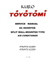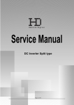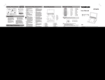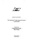
1
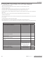
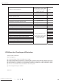
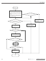
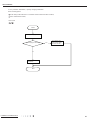
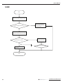
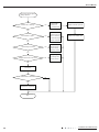
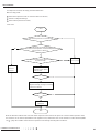
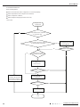
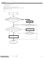
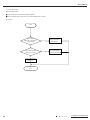
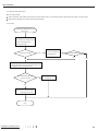
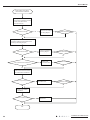
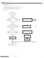
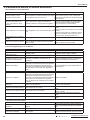
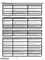
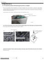
Service Manual
9. Maintenance
9.1 Precautions before Performing Inspection or Repair
There are high-capacity electrolytic capacitors on the outdoor mainboard. Thus, even the power is cut off, there is high voltage
inside the capacitors and it needs more than 20min to reduce the voltage to safety value. Touching the electrolytic capacitor within
20min after cutting the power will cause electric shock. If maintenance is needed, follow the steps below to discharge electricity of
electrolytic capacitor after power off.
(1) Open the top cover of outdoor unit and then remove the cover of electric box cover.
electric box cover
outdoor mainboard(AP1)
Fig.29
(2) As shown in the fig below, connect the plug of discharge resistance (about 100ohm, 20W) (if there is no discharge resistance,
you can use the plug of soldering iron) to point A and B of electrolytic capacitor. There will be sparks when touching them. Press
them forcibly for 30s to discharge electricity of electrolytic capacitor.
outdoor mainboard(AP1)
18K:
discharge resistance or
plug of soldering iron
24/28K:
A
B
A
B
B
A
Fig.30
(3) After finish discharging electricity, measure the voltage between point A and B with universal meter to make sure if electricity
discharging is completed, in order to prevent electric shock. If the voltage between the two points is below 20V, you can perform
maintenance safely.
Installation and Maintenance
27
Service Manual
9.2 Flashing LED of Indoor/Outdoor Unit and Primary Judgement
1. Requirement of malfunction display
When several malfunctions happen at the same time, malfunction codes will be displayed circularly.
2. Malfunction display method
(1) Hardware malfunction: it will be displayed immediately, please refer to “Malfunction status sheet”;
(2) Operation status: it will be displayed immediately, please refer to “Malfunction status sheet”;
(3) Other malfunction: It will be displayed after the compressor has been stopped for 200s, please refer to “Malfunction
status sheet”.
(Note: when the compressor starts up again, malfunction display waiting time (200s) will be cleared.)
3. Malfunction display control
Indoor unit displays malfunction code as shown in the sheet below. ODU communication light will be off for 1s and then blink
for 1s circularly.
4. Viewing malfunction code through remote controller
Enter viewing malfunction code: pressing light button for 6 times within 3S to view malfunction code;
Exit viewing malfunction code: pressing light button for 6 times within 3S or after the malfunction code is displayed for 5min.
Malfunction status sheet
Malfunction name
Zero cross detection circuit malfunction
Malfunction protection of jumper cap
Malfunction type
Hardware malfunction
Hardware malfunction
Nixie tube
U8
C5
Feedback of without IDU motor
Indoor ambient temperature sensor is open/short circuited
Hardware malfunction
Hardware malfunction
H6
F1
Indoor evaporator temperature sensor is open/short circuited
Liquid valve temperature sensor is open/short circuited
Hardware malfunction
Hardware malfunction
F2
b5
Gas valve temperature sensor is open/short circuited
Modular temperature sensor is open/short circuited
Hardware malfunction
Hardware malfunction
b7
P7
Outdoor ambient temperature sensor is open/short circuited
Outdoor condenser inlet pipe temperature sensor is
open/short circuited (commercial)
Outdoor condenser middle pipe temperature sensor is
open/short circuited
Outdoor condenser outlet pipe temperature sensor is
open/short circuited (commercial)
Outdoor discharge temperature sensor is open/short
circuited
Communication malfunction
Malfunction of phase current detection circuit for compressor
Compressor demagnetization protection
Hardware malfunction
Hardware malfunction
F4
A5
Hardware malfunction
F4
Hardware malfunction
A7
Hardware malfunction
F5
Hardware malfunction
Hardware malfunction
E6
U1
Malfunction of voltage dropping for DC bus-bar
Module high temperature protection
Refrigerant lacking or blockage protection of system (not
available for residential ODU)
Charging malfunction of capacitor
High pressure protection of system
Low pressure protection of system (reserved)
28
Viewing malfunction code
through remote controller within
200s; displayed directly on
nixietube after 200s
HE
U3
P8
F0
Hardware malfunction
PU
Hardware malfunction
Hardware malfunction
E1
E3
Installation and Maintenance
43
43
44
Service Manual
44
45
45
46
46
●
●
Communication failure
failure with
with Unit
Unit A
A
Communication
Communication failure
failure with
with Unit
Unit B
B
Communication
Communication
failure
with
Unit
C
Communication failure with Unit C
Communication failure
failure with
with Unit
Unit D
D
Communication
Ƽ
Ƽ
47 Unit
Unit A
A freeze
freeze protection
protection
47
48 Unit
Unit B
B freeze
freeze protection
protection
48
Compressor
overload
protection
49
Unit
C
freeze
protection
49 Unit C freeze protection
50 Unit
Unit D
D freeze
freeze protection
protection
50
51
Unit
A
overheating
prevention
protection
oor A
unoverheating
it and outdoor prevention
unit do not mprotection
atch
51 Ind
Unit
52
Unit
B
overheating
prevention
protection
M
a
l
f
u
n
c
t
i
o
n
o
f
m
e
m
o
r
y
c
h
i
p
52 Unit B overheating prevention protection
53 Wrong
Unit C
Cconnection
overheating
prevention protection
protection
of communication
wire or malfunction of
53
Unit
overheating
prevention
expansion valve
54 electronic
Unit D
D overheating
overheating
prevention protection
protection
54
Unit
prevention
55
55
56
56
57
57
58
58
○
○
●
●
Ƽ
Ƽ
Ƽ
Ƽ
○
○
○
○
Ƽ
○
Ƽ code ○
Viewing malfunction
○ within●
●
○
through remote controller
●
●
● on ●
200s; displayed directly
Ƽ
●
nixietube after Ƽ
200s
●
○
Ƽ
Hardware malfu○
nction Ƽ
●ction Ƽ
Ƽ
Hardware malfu●
n
Ƽ
Ƽ
Hardware malfunction
○
○
Malfunction
of complete units
detection or expansion valve malfunction
Hardware malfunction
Unit A
A communication
communication
wirecurrent
misconnection
●
Unit
wire
misconnection
or expansion valve malfunction
●
Ma
l
f
u
n
c
t
i
o
n
p
r
o
t
e
c
t
i
o
n
o
f
o
u
t
d
o
o
r
f
a
n
1
H
a
r
d
w
a
r
e
m
a
l
f
u
n
Unit B communication wire misconnection or expansion valve malfunction
Ƽction
Unit B communication wire misconnection or expansion valve malfunction
Ƽ
Detection
status of wrong wire
connection
of communication
wire valve malfunction
Unit C
C communication
communication
misconnection
or expansion
expansion
○
Unit
wire misconnection
or
valve malfunction
○
Operation status
orUnit
malfunction
of
electronic
expansion
valve
D communication
communication wire
wire misconnection
misconnection or
or expansion
expansion valve
valve malfunction
malfunction
●
Unit D
●
Mode conflict
Operation status
Refrigerant recycling mode
X-fan
Defrosting or oil return in heating mode
Ƽ
Ƽ
○
○
○
○
○
○
●
●
●
●
Operation status
Operation status
Operation status
Start failure of compressor
Note: discharge
discharge the
the position
position in
in below
below pictures
pictures with
with discharge
discharge resistance
resistance after
after open
open the
the top
top cover
cover and
and
Note:
High discharge temperature protection of compressor
check ifif the
the voltage
voltage is
is below
below 20V
20V with
with universal
universal meter,
meter, then
then begin
begin to
to check.
check.
check
Overload protection
Whole unit overcurrent protection
14/18K:
14/18K:
Compressor phase current protection
24/28K:
24/28K:
Compressor desynchronizing
Compressor phase-lacking/phase-inverse protection
IPM modular protection
Viewing malfunction code
through remote controller within
200s; displayed directly on
nixietube after 200s
●
●
●
●
Ƽ
Ƽ
Ƽ
Ƽ
Ƽ
Ƽ
Ƽ
Ƽ
H3
Ƽ
Ƽ
Ƽ
Ƽ
Ƽ
LƼ
P
Ƽ
EƼ
E
Ƽ
dn
Ƽ
●
●
●
●
●
●
●
●
●
●
●
●
●
●
●
●
●
●
●
●
●
●
○
○
Ƽ
Ƽ
Ƽ
Ƽ
○
○
○
○
E7
Ƽ
Ƽ
Ƽ
Ƽ
Ƽ
Ƽ
U5
○
○
L○
3
dd
○
Fo
AL
H1
Lc
E4
E8
E5
P5
H7
Ld
H5
DC bus-bar low voltage protection
DC bus-bar high voltage protection
PL
PH
PFC protection
The four-way valve is abnormal
HC
U7
9.3 Malfunction Checking and Elimination
1 IPM
IPM protection
protection malfunction:
malfunction:
1
Main checking
checking point:
point:
Main
●
●
●
●
If the
the input
input voltage
voltage of
of the
the unit
unit is
is within
within normal
normal range?
range?
If
If the
the connection
connection wire
wire of
of compressor
compressor is
is connected
connected well?
well? Is
Is itit loose?
loose? If
If the
the connection
connection sequence
sequence is
is correct?
correct?
If
●
●
●
●
If the
the resistance
resistance of
of compressor
compressor coil
coil is
is normal?
normal? If
If the
the isolation
isolation of
of compressor
compressor coil
coil with
with copper
copper pipe
pipe is
is good?
good?
If
If the
the unit
unit is
is overloaded?
overloaded? If
If the
the heat
heat radiation
radiation of
of the
the unit
unit is
is good?
good?
If
●
●
If the
the refrigerant
refrigerant charge
charge is
is suitable?
suitable?
If
Flow chart:
chart:
Flow
Installation and Maintenance
29
Service Manual
Energize the unit
Please check:
1. if the indoor and outdoor heat exchanges are
dirty, if there is obstacle to affect the radiation;
2. if the indoor and outdoor fans are running
normally;
3. if the pressure of the system is too high;
4. if the refrigerant is too much which causes
the high level of pressure;
If the above cases are existed?
Yes
No
Correct according to the service
manual and then energize the
unit to operate
No
If the wire of compressor is connected
well and correctly?
Yes
Reconnect the wire of the
compressor according to the
correct wiring method
Test the resistance between
the three phases
No
If the resistance is normal?
Yes
Test the isolation impedance
between the three phases of the
compressor and thecopper pipe
Yes
If the resistance is above 500M
?
No
Replace the
compressor
Malfunction is eliminated
Yes
No
Replace the outdoor
mainboard
End
30
Installation and Maintenance
Service Manual
2. PFC protection malfunction, capacity charging malfunction
Main checking points:
If the wiring of the induction is connected well and if the induction is broken;
If the mainboard is broken;
Flow chart:
Start
Check if power supply is normal
Power supply is abnormal?
Yes
Turn on the unit
after power supply
resumes normal
No
Replace the outdoor
mainboard
End
Installation and Maintenance
31
Service Manual
Start
Check If the power supply is normal
Turn on the unit after the
Power supply is abnormal
power supply resumes to
Yes
normal situation
No
Check if the outdoor induction is broken
The induction is broken
Replace the induction
Yes
No
Replace the outdoor
mainboard
No
Malfunction is eliminated
Yes
End
32
Installation and Maintenance
Service Manual
3. Compressor desynchronizing malfunction
Main checking points:
If the pressure of the system is too high;
If the eletric expansion valve is working normally or it is broken;
If the radiation of the unit is good;
Flow chart:
The unit appears desynchronizing
as soon as energizing and starting
The stop duration of the compressor is longer
No
than 3min?
Yes
The wiring of the compressor is
connected properly?
Yes
No
Reconnect the wire properly
No
Eliminate the malfunction
The eletric expansion valve is broken?
Yes
No
No
Yes
Replace the eletric
expansion valve
Eliminate the malfunction
Yes
Replace the outdoor mainboard
Eliminate the malfunction
Yes
No
Replace the compressor
End
Installation and Maintenance
33
Service Manual
Desynchronizing happens
during operation
Outdoor unit is working?
No
Check if fan
terminal is
connected well
Replace the fan capacitor
No
Improve radiation
situation of the unit
(such as cleaning
the heat exchanger,
improve ventilation
Replace the outdoor unit
Yes
Unit radiation is good?
Yes
Input voltage is normal?
No
Turn on the unit
after the power
supply voltage
resumes normal
Yes
Charge refrigerant
Refrigerant amount is too much?
Yes
according to the
service manual
No
Replace the outdoor
mainboard
Eliminate the malfunction
Yes
No
Replace the compressor
End
34
Installation and Maintenance
Service Manual
4. Compressor overload, diacharge protectionmalfunction
Main checking points:
If the eletric expansion valve is connected well or it is broken;
If there is refrigerant leakage;
If the overload protector is broken;
Flow chart:
Start
If the overload protector is connected well?
No
Yes
No
Check the resistance between the two
ends of the overload protector in ambient temperature,
if the resistance is below 1k
Yes
If the wiring of the eletric expansion valve
is coonected well?
No
Reconnect according
to the wiring diagram
Yes
Replace the
overload
protector
Check the coil of the eletric
expansion valve, replace
it if it is broken
Eliminate the malfunction
Yes
No
Check the refrigerant status, if there is
refrigerant leakage, recharge it according
to the service manual
Eliminate the malfunction
Yes
No
Replace outdoor
mainboard
End
Note: the detection method of the coil of the eletric expansion valve: there is five pieces of coil of the eletric expansion valve,
the resistance of one of them (the leftmost or the rightmost one) is almost the same as the resistance of other terminal (within
100
). Judge the condition of the electronic expansion valve through detecting these resistance.
Installation and Maintenance
35
Service Manual
5. Start failuremalfunction
Main checking points:
If the connection wire of the compressor is connected properly;
If the stop duration of the compressor is sufficient;
If the compressor is broken;
If the
; refrigerant charging amount is too much;
Flow chart:
Energize and
start the unit
If the stop duration of the compressor
is longer than 3min
No
Yes
If the connection wire of the compressor
is connected well and correctly
No
Yes
No
No
If the refrigerant charging
amount is too much
Reconnect the connection wire
of the compressor according
to the wiring diagram
Eliminate the malfunction
Yes
Yes
Charge the refrigerant
according to the
service manual
Eliminate the malfunction
Yes
No
The stop duration of the unit is
not enough, the high and low
pressure of the system is not
balanced, restart it after 3min
Replace the outdoor
mainboard
Eliminate the malfunction
Yes
No
Replace the compressor
End
36
Installation and Maintenance
Service Manual
6. Temperature sensor malfunction
Main checking points:
If the temperature; sensor is damaged or broken
If the terminal of the temperature sensor is loosended or not connected;
If the mainboard is broken;
Flow chart:
Start
Check whether the wiring terminal between
temperature sensor and controller is loosened or poorly
contacted?
Yes
Insert the temperature
sensor tightly
No
Eliminate the
malfunction
No
Check whether the
temperature senspr is normal according to
No
Replace the temperature sensor
with the same model
No
Eliminate the malfunction6.
resistance table
Yes
Yes
Yes
Replace the controller with
the same model
End
Installation and Maintenance
37
Service Manual
7. DC fan malfunction
Main checking points:
If the outdoor fan is blocked by foreign objects;
The connection wire of DC fan is connected reliably? If it is loose?
Flow chart:
Start
Check if the
outdoor fan is blocked by
Yes
foreign objects?
Turn on the unit
after removing the
foreign objects
No
If the connection wire
of DC fan is loose?
Yes
Turn on the unit after
the connection wire
is properly connected
No
Replace the outdoor
mainboard
End
38
Installation and Maintenance
Service Manual
8. Communication malfunction
Main checking points:
If the connection wire between the indoor unit and outdoor unit is connected well, if the wires inside the unit is connected well;
If the indoor mainboard or outdoor main board is broken;
Flow chart:
Communication malfunction of some
indoor units
De-energize,check if the connection
wire of indoor and outdoor unit and
the wire of the eletric box is
connected correctly
Connected correctly
No
Reconnect according to
the wiring diagram
Eliminate the malfunction
No
Yes
Yes
De-energize, change the communication wire of the wellcommunicated indoor unit and malfunction indoor unit,
then energize the unit and wait for 3min
The malfunction indoor unit
resumes normal
Yes
Replace outdoor
mainboard
No
Replace the mainboard of the
malfunction indoor unit
End
Installation and Maintenance
39
Service Manual
All the indoor units appear
communication malfunction
De-energize,check if the connection
wire of indoor and outdoor unit and
the wire of the eletric box is
connected correctly
Connected correctly?
Reconnect according to
No
the wiring diagram
Eliminate the malfunction
Yes
Yes
De-energize, check if the connection wire between
the outdoor mainboard and the filter board
according to the wiring diagram
Connected correctly?
No
Reconnect according to
the wiring diagram
Eliminate the malfunction
Yes
No
Yes
Yes
The connection wire is broken?
Replace the
connection wire
Eliminate the malfunction
Yes
No
No
Check if there is power input
bewtween the netrual wire and live
wire of the outdoor mainboard
There is power input?
No
Replace the filter board of
the outdoor unit
Eliminate the malfunction
Yes
No
Yes
Replace the outdoor
mainboard
Resume communication?
No
Replace indoor
mainboard
Yes
End
40
Installation and Maintenance
Service Manual
9. Anti-high temperatureand overload malfunction
Main checking points:
If the outdoor ambient temperature is within the normal range;
If the indoor fan and outdoor fan are running normally;
If the indoor and outdoor radiation environment is good;
Flow chart:
Start
If the outdoor ambient temperature
is above 53
Yes
It is a normal protection, please
operate the unit after the outdoor
ambient temperature has changed
Yes
Improve the radiation
environment of the unit
No
If the indoor and outdoor radiation
is insufficient
No
If the outdoor fan is working normally
No
Check if the terminal of the fan is
connected well, if the fan is broken
Yes
Replace fan capacitor
Replace outdoor
mainboard
Replace outdoor fan
End
Installation and Maintenance
41
Service Manual
9.4 Maintenance Method for Normal Malfunction
1. Air Conditioner Can't be Started Up
Possible Causes
No power supply, or poor
connection for power plug
Discriminating Method (Air conditioner Status)
Troubleshooting
Confirm whether it's due to power failure. If yes,
After energization, operation indicator isn’t bright wait for power recovery. If not, check power
and the buzzer can't give out sound
supply circuit and make sure the power plug is
connected well.
Wrong wire connection between
indoor unit and outdoor unit,
Under normal power supply circumstances,
or poor connection for wiring
operation indicator isn't bright after energization
terminals
Check the circuit according to circuit diagram
and connect wires correctly. Make sure all
wiring terminals are connected firmly
Make sure the air conditioner is grounded
reliably
Make sure wires of air conditioner is connected
After energization, room circuit breaker trips off at
Electric leakage for air conditioner
correctly
once
Check the wiring inside air conditioner. Check
whether the insulation layer of power cord is
damaged; if yes, place the power cord.
Model selection for air switch is
After energization, air switch trips off
Select proper air switch
improper
After energization, operation indicator is bright,
Replace batteries for remote controller
Malfunction of remote controller while no display on remote controller or buttons
Repair or replace remote controller
have no action.
2. Poor Cooling (Heating) for Air Conditioner
Possible Causes
Set temperature is improper
Rotation speed of the IDU fan
motor is set too low
Filter of indoor unit is blocked
Discriminating Method (Air conditioner Status)
Troubleshooting
Observe the set temperature on remote controller Adjust the set temperature
Small wind blow
Set the fan speed at high or medium
Check the filter to see it's blocked
Clean the filter
Check whether the installation postion is proper
Installation position for indoor unit
Adjust the installation position, and install the
according to installation requirement for air
and outdoor unit is improper
rainproof and sunproof for outdoor unit
conditioner
Discharged air temperature during cooling is
higher than normal discharged wind temperature;
Discharged air temperature during heating is
Find out the leakage causes and deal with it.
Refrigerant is leaking
lower than normal discharged wind temperature; Add refrigerant.
Unit's pressure is much lower than regulated
range
Malfunction of 4-way valve
Blow cold wind during heating
Replace the 4-way valve
Discharged air temperature during cooling is
higher than normal discharged wind temperature;
Discharged air temperature during heating is
Malfunction of capillary
lower than normal discharged wind temperature; Replace the capillary
Unit't pressure is much lower than regulated
range. If refrigerant isn’t leaking, part of capillary
is blocked
Flow volume of valve is
The pressure of valves is much lower than that
Open the valve completely
insufficient
stated in the specification
Refer to point 3 of maintenance method for
Malfunction of horizontal louver Horizontal louver can’t swing
details
Refer to troubleshooting for H6 for maintenance
Malfunction of the IDU fan motor The IDU fan motor can’t operate
method in details
Refer to point 4 of maintenance method for
Malfunction of the ODU fan motor The ODU fan motor can't operate
details
Refer to point 5 of maintenance method for
Malfunction of compressor
Compressor can't operate
details
3. Horizontal Louver Can't Swing
Possible Causes
Wrong wire connection, or poor
connection
Check the wiring status according to circuit
diagram
Stepping motor is damaged
Stepping motor can't operate
Others are all normal, while horizontal louver
can't operate
Main board is damaged
42
Discriminating Method (Air conditioner Status)
Troubleshooting
Connect wires according to wiring diagram to
make sure all wiring terminals are connected
firmly
Repair or replace stepping motor
Replace the main board with the same model
Installation and Maintenance
Service Manual
4. ODU Fan Motor Can't Operate
Possible causes
Wrong wire connection, or poor
connection
Discriminating method (air conditioner status)
Check the wiring status according to circuit
diagram
Troubleshooting
Connect wires according to wiring diagram to
make sure all wiring terminals are connected
firmly
Measure the capacity of fan capacitor with an
Capacity of the ODU fan motor is universal meter and find that the capacity is out of
Replace the capacity of fan
damaged
the deviation range indicated on the nameplate of
fan capacitor.
Power voltage is a little low or
Use universal meter to measure the power supply
Suggest to equip with voltage regulator
high
voltage. The voltage is a little high or low
When unit is on, cooling/heating performance
Change compressor oil and refrigerant. If no
Motor of outdoor unit is damaged is bad and ODU compressor generates a lot of
better, replace the compressor with a new one
noise and heat.
5. Compressor Can't Operate
Possible causes
Wrong wire connection, or poor
connection
Discriminating method (air conditioner status)
Check the wiring status according to circuit
diagram
Troubleshooting
Connect wires according to wiring diagram to
make sure all wiring terminals are connected
firmly
Measure the capacity of fan capacitor with an
universal meter and find that the capacity is out of
Replace the compressor capacitor
the deviation range indicated on the nameplate of
fan capacitor.
Power voltage is a little low or
Use universal meter to measure the power supply
Suggest to equip with voltage regulator
high
voltage. The voltage is a little high or low
Use universal meter to measure the resistance
Coil of compressor is burnt out
Repair or replace compressor
between compressor terminals and it's 0
Cylinder of compressor is blocked Compressor can't operate
Repair or replace compressor
Capacity of compressor is
damaged
6. Air Conditioner is Leaking
Possible causes
Discriminating method (air conditioner status)
Troubleshooting
Eliminate the foreign objects inside the drain
pipe
Replace drain pipe
Drain pipe is blocked
Water leaking from indoor unit
Drain pipe is broken
Water leaking from drain pipe
Water leaking from the pipe connection place of
Wrap it again and bundle it tightly
indoor unit
Wrapping is not tight
7. Abnormal Sound and Vibration
Possible causes
Discriminating method (air conditioner status)
When turn on or turn off the unit,
the panel and other parts will
There's the sound of "PAPA"
expand and there's abnormal
sound
When turn on or turn off the unit,
there's abnormal sound due
Water-running sound can be heard
to flow of refrigerant inside air
conditioner
Foreign objects inside the indoor
unit or there're parts touching
There's abnormal sound fro indoor unit
together inside the indoor unit
Foreign objects inside the outdoor
unit or there're parts touching
There's abnormal sound fro outdoor unit
together inside the outdoor unit
Short circuit inside the magnetic During heating, the way valve has abnormal
coil
electromagnetic sound
Abnormal shake of compressor
Outdoor unit gives out abnormal sound
Abnormal sound inside the
compressor
Abnormal sound inside the compressor
Installation and Maintenance
Troubleshooting
Normal phenomenon. Abnormal sound will
disappear after a few minutes.
Normal phenomenon. Abnormal sound will
disappear after a few minutes.
Remove foreign objects. Adjust all parts'
position of indoor unit, tighten screws and stick
damping plaster between connected parts
Remove foreign objects. Adjust all parts'
position of outdoor unit, tighten screws and
stick damping plaster between connected parts
Replace magnetic coil
Adjust the support foot mat of compressor,
tighten the bolts
If add too much refrigerant during maintenance,
please reduce refrigerant properly. Replace
compressor for other circumstances.
43