1
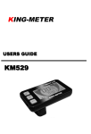
KING-METER
USERS GUIDE
KM5S –LCD
中文 1-31 页
English P32-64
Contents
About the User Manual ··················································32
Appearance and Size ·····················································33
Material and Color ···················································33
Function Summary and Button Definition ····················34
Function Summary ··················································34
Monitor Area ····························································34
Button Definition ·····················································35
Operation Cautions ························································35
Installation Instruction ···················································36
Normal Operation ···························································36
Power On/Off ···························································36
Display Interface ·····················································36
Push Cruise Control················································37
Turn on/off Backlight ··············································38
PAS Level Selection ················································38
Battery Indicator······················································38
Motor Power Monitor ··············································39
Error Code Information ···········································39
User Setting ····································································40
Preparation before Starting ····································40
General Setting························································40
Trip Distance and Trip Time Clearance ···········40
Backlight Contrast ···········································41
Power-on Password Enable/Disable ······················41
Power-on Password Enable·····························42
1
Power-on Password Modify ·····························43
Normal Parameter Setting ······································43
Wheel Diameter Setting ···································43
Speed-limit Setting ···········································44
Personalized Parameter Setting ····································45
System Parameter Setting ······································45
Battery Power Bar Setting ······································46
Pedal Assistant Level Setting ·································46
Pedal Assistant Level Select ···························46
PAS Ratio Modify··············································48
Controller Over-Current Cut Setting ······················48
Pedal Assistant Sensor Setting ······························49
The Direction of Pedal Assistant Sensor Setting
··········································································49
The Sensitivity of PAS Setting ·························49
Proporation parameter Setting of PAS ············50
Speed Sensor Selection··········································50
Throttle Definition ···················································51
Throttle Enable/Disable····································51
Throttle Level Enable/Disable··························51
System Setting ························································52
Delay time setting of battery power ················52
Max speed limited ············································52
Button PAS Setting ·················································52
PAS Speed Setting ···········································52
Slowly Start up Setting ····································52
2
Exit setting······································································55
Recover default setting ··················································55
FAQ ·················································································57
Barcode ··········································································57
Quality assurance and warranty scope ························58
Connection layout ··························································59
Version changes ·····························································60
Attached list 1:Error code definition···························61
Attached list 2: Password table··································61
Attached list 3:Personality Parameter setting············62
Attached list 4:Power assist table ······························63
Attached list 5:symbol definition ································64
3
About the User Manual
Dear users,
To ensure better performance of your e-bike, please
read through the KM5S product introduction carefully before
using. We will use the most concise words to inform you of
all the details(including the hardware installation, setting
and normal operation use of the display)when using our
display. Meanwhile, the introduction will also help you to
solve the possible confusion and malfunctions.
32
Appearance and Size
Material and Color
KM5S products are made of PC. Under the temperature
of -20 to 60℃, the shell material can ensure normal usage
and good mechanical performance.
Real product and dimension figure (unit: mm)
33
Function Summary and Button Definition
Function Summary
KM5S provides a wide range of functions and indicators
to fit the users’ needs. The indicated contents are as
following.
◆Battery Indicator
◆Motor Power Ratio
◆Speed Display (including running speed, max speed
and average speed)
◆Trip distance and total distance
◆Trip time display of single
◆Cruise control
◆Headlight On/Off
◆Error Code Indicator
◆Various Parameters Setting (like wheel size, speed
-limited, battery level bar, PAS level, controller limited
current, max speed, password enable, and so on.)
◆Recover Default Setting
Monitor Area
Monitor Area
34
Button Definition
KM5S has three buttons. They are
is named as “MODE”.
the following introduction,
is named as “UP” and
. In
is named as “DOWN”.
Operation Cautions
Be care of the safety use. Don’t attempt to release the
connector when battery is on power.
Try to avoid hitting.
Don’t split the waterproof sticker to avoid affecting
the waterproof performance.
Don’t modify system
parameters disorder.
parameters
to
Make the display repaired when error code
appears.
35
avoid
Installation Instruction
Fix the display onto the handlebar and adjust to an
appropriate visual angle. Tighten all the connectors.
Normal Operation
Power On/Off
Hold Mode button for 2 seconds then the display will
power on, and the display will the power on the controller.
With display on, hold MODE to turn off power supply of the
e-bike. With the display off, the display and controller shut
down. The leakage current is less than 1 uA.
When parking e-bike for more than 10 minutes,
the display shut down automatically.
Display Interface
After starting up the display, default show is running
speed. Press MODE to change the indicated information in
sequence as below: Running Speed (Km/h) → Average
Speed (Km/h) → Max Speed (Km/h) → Trip Distance (km)
→ Total Distance (km) → Travel Time → Running Speed
(Km/h).
36
Running Speed
Average Speed
Trip Time
Trip Distance
Max Speed
Total Distance
Push Cruise Control
Hold DOWN for 2 seconds to enter the mode of power
assistant walk. The e-bike will go on at a uniform speed of 6
Km/h. PUS shows on the screen.
Push Cruise Control
“Push Cruise Control” function can only be used
as pushing the e-bike by hands. Please don’t use
this function when riding.
37
Turn on/off Backlight
Hold UP 2 seconds to turn on the backlight of the
display, the headlight will be power on at the same time.
Hold UP for 2 seconds again, backlight turned off.
Turn On/Off Backlight
PAS Level Selection
Hold UP or DOWN to change the output power of the
motor. The power ranges from level 1 to level 5. Level 1 is
the minimum power. Level 5 is the maximum power. The
default value is level 1.
PAS Level
Battery Indicator
The 5 battery bars represent the capacity of the battery.
When the battery is in low voltage, battery frame will flash to
notice that the battery needs to be recharged immediately.
38
Low Voltage Flash
Battery Indicator
Motor Power Monitor
Motor power showed as below:
Motor Output Power
Error Code Information
If there is something wrong with the electronic control
system, the error code will appear automatically. Here is the
detail information of the error code in Table 1 attached.
Error Code
Make the display repaired when error code
appears.
39
User Setting
Preparation before Starting
Make sure all connectors tightened and the cables
without damage.
General Setting
Press MODE button to start the display, then hold both
UP and DOWN for 2 seconds to enter the setting menu.
Trip Distance and Trip Time Clearance
TC means trip distance clearance. Press UP or DOWN
to choose yes or no to clear the trip distance.
Trip distance and trip time will be cleared at the
same time.
Trip Distance Clearance
40
Backlight Contrast
BL means backlight. Level 1 is the low brightness. Level
2 is the middle brightness. Level 3 is high brightness. The
default level is 1. Bottom of the screen prompts SET2.
Press UP or DOWN to modify the backlight brightness.
Hold MODE to confirm the modification and exit the general
setting.
Backlight Brightness
Pressing UP and DOWN can change the backlight
lighting. Long press MODE is to confirm and quit Setting
Mode.
Backlight setting Interface
Power-on Password Enable/Disable
The character “-P-” on the bottom of the screen means
the page of password. Hold UP and DOWN both up to 2
seconds enter normal setting , while hold both UP and
41
MODE 2 seconds again will enter power-on password
enable/disable page.
Press UP/DOWN to change the number .Press MODE
to select digit one by one. After 4-digite of the correct
password entered, press MODE to confirm then select
password enable or disable.
Password Entering Page
Power-on Password Enable
Press UP/DOWN to select Y or N, and press MODE to
confirm. Power-on Password default disable.
y = Power-on Password Enable
n = Power-on Password Disable
Password Disable Page
42
Power-on Password Modify
UP and DOWN is to change the number, and MODE is
to select digit one by one, finally to hold MODE to confirm
the modification.
Password Modify Page
Normal Parameter Setting
Hold both UP and DOWN for 2 seconds to enter User
setting .But hold both DOWN and MODE over 2 seconds is
to enter password 0512 to modify the wheel size.
Password Inputting Page
Wheel Diameter Setting
43
Press UP and DOWN to select the correct value to
match the wheel diameter. Selectable values include: 16, 18,
20, 22, 24, 26, 700C, 28, 29. Default diameter is 26 inch.
Ld means Wheel Diameter.
Wheel Diameter Setting Page
Speed-limit Setting
When the running speed is faster than MAX SPEED,
the controller will cut off the motor power. MAX SPEED
default setting is 25Km/h. LS means Limit Speed 12Km/h to
40Km/h is selectable. Press UP/DOWN to select the favorite
value, then hold MODE over 2 seconds to confirm and quit
the setting mode.
Limit Speed Setting Page
44
Personalized Parameter Setting
Personalized Parameter Setting can match variety
requirements in use. Settings items are : Battery Power Bar
Setting, Pedal assistant level Setting, Over-current Cut ,
Pedal Assistant Sensor Setting, Speed Sensor Setting and
Delay Time Setting. For the details, please see the
Attached List 2.
System Parameter Setting
Hold UP and DOWN both over 2 seconds to enter
normal setting, while hold UP and DOWN both again is to
set up System Parameter, password 2962 must be entered.
MODE is to confirm and enter System Parameter
Setting page, you can select the option which you want.
System Parameter Password Input
Press UP/DOWN to select, and press MODE to enter
the corresponding setting page.
45
Option Select Page
Battery Power Bar Setting
Each bar represents a voltage value. 5 voltage values
MUST BE entered one by one.
Press MODE to confirm and UP/DOWN to select the
value.
VOL = voltage
Battery Power Bar Setting
Pedal Assistant Level Setting
Pedal Assistant Level Select
46
In Pedal Assistant Level Setting , there are 8 modes to
select :0-3, 1-3, 0-5, 1-5, 0-7, 1-7, 0-9, 1-9. Press
UP/DOWN to select the mode, and press MODE to confirm,
then change the ratio of each PAS level.
PAS Mode Select Page
0-3 or 1-3:
PAS1 also shows ECO,
PAS2 also shows TOUR,
PAS3 also shows BOOST.
0-5 or 1-5:
PAS1 also shows ECO,
PAS2 also shows CITY,
PAS3 also shows TOUR,
PAS4 also shows POWER,
PAS5 also shows BOOST.
0-7 or 1-7:
PAS1 also shows ECO,
PAS2 also shows ECO,
PAS3 also shows CITY,
PAS4 also shows CITY,
PAS5 also shows TOUR,
PAS6 also shows POWER,
PAS7 also shows BOOST.
0-9 or 1-9:
PAS1 or 2 also shows ECO,
PAS3 or 4 also shows CITY,
PAS5 or 6 also shows TOUR,
PAS7 or 8 also shows
POWER,
PAS9 also shows BOOST.
47
PAS Ratio Modify
To modify the value of PAS ratio will meet the
different requirements.
Take the 1 level for example, “45-55 percent” is the
range value, bottom value can be modified, and the default
is 50 percent. MODE is used to confirm and turn to the next
PAS ratio setting. After all PAS ratio inputted, please hold
MODE over 2 seconds to confirm the modification and turn
to controller Over-current Cut setting (MODE back to pedal
assistant level select page). For the details, please see
Attached List 4.
PAS Ratio Page
Controller Over-Current Cut Setting
CUR means current. CUR value can be changed from
7.0A to 22.0A. Press UP/DOWN is to change the value of
the current, and hold MODE to confirm the setting and turn
to PAS sensor setting.15A is the default value of controller
over-current cut.
According to the different controller, the value
might not be able to be 22A.
48
CUR Setting Page
Pedal Assistant Sensor Setting
The Direction of Pedal Assistant Sensor Setting
PAS means Pedal Assistant System. “run-F” means
forward direction, while “run-b” means back direction. Press
UP/DOWN to select F or b, and press MODE to confirm and
turn to PAS sensitivity setting. The default direction is
forward.
Direction of PAS Sensor Setting
The Sensitivity of PAS Setting
SCN means the sensitivity of PAS, and 2 to 9 can be
selected.2 is strongest, 9 is the weakest. UP/DOWN is to
select sensitivity value, and MODE is to confirm selection
and turn to magnet disk setting. SCN default value is 2.
49
The Sensitivity of PAS Setting
Proportion parameters Setting Of PAS
N means the proportion parameter of PAS. Press
UP/DOWN to select the parameter, the more power, the
more PAS feeling.
Proportion parameter of PAS
Speed Sensor Selection
SPS means Speed Sensor. Press UP/DOWN to select
the quantity of magnet head (the range is from 1 to 9), and
press MODE to confirm and turn to Throttle Definition page.
SPS default value is 1.
Speed Sensor Selection
50
Throttle Definition
Throttle Enable/Disable
HL means throttle load, HL:N means function
disable ,HL:Y means function enable .
When HL=Y, throttle can control the function. Press
UP/DOWN to select Y, and press MODE to confirm the
selection, otherwise select N to turn to Throttle Vector
Enable Setting.
HL default value is N.
Throttle Enable/Disable Page
Throttle Level Enable/Disable
HND means throttle. HF:Y means throttle vector
enable , HF:N means throttle vector disable. When HF=Y,
turn throttle to change the running speed. Press UP/DOWN
to select Y or N, and hold MODE to confirm the selection
and quitting. Press MODE to confirm and turn to throttle
definition page.
51
Throttle Level Enable/Disable Page
System Setting
Delay time setting of battery power
DLY means delay time of battery power. Choose delay
time 3/6/12s through pressing UP/DOWN, then shortly press
MODE, and enter the max speed limited. The default time is
3s.
Delay time of battery power interface
Max speed limited
MAX SPD means max speed limited. Set the max
speed when pressing UP/DOWN from 25-40 Km/h. Long
time to press MODE, then exit setting. The default is
40Km/h.
52
The standard speed limit setting is based on this
setting, not more than this setting value.
This setting is the priority version
Interface of max speed limited setting
Button PAS Setting
PUS means pushing. Press UP/DOWN to choose Y/N.
Short press MODE, Y means enable, N means disable.
Short press MODE to confirm and enter into PAS speed
setting. The default value is Y.
Interface of PAS pushing
PAS Speed Setting
Through setting PAS to adjust push speed to meet
rider’s requirements.
53
The scope is “20%-35%”by pressing UP/DOWN,
short press MODE to enter into slowly start up. Default value
is 25%.
Interface of PAS speed setting
Slowly Start up Setting
SSP means slowly start up. The scope is 1-4, 4
means the slowest. Press UP/DOWN to choose. Long press
MODE to confirm and exit setting. The default value is 1.
Interface of slowly setting up
54
Exit setting
In the setting state, short press MODE (less than 2s) is
to confirm the input. Long press MODE (more than 2s) is for
saving the setting, then quit the setting state. Long press
DOWN (more than 2s), is to cancel the operating but not
saving setting data.
If there is not any operating in one minute, display will
exit the setting state.
Recover default setting
DEF means recover default. Both press UP+MODE to
enter recover default setting. Pressing UP, DOWN to
convert Y or N. N means do not need to recover default
setting; Y means entering into password setting. Otherwise,
display will exit. The default state is N.
Restore Default Setting Interface
Input password: 0368. Short press MODE, UP/DOWN
can increase or reduce the number. After inputting 4
55
passwords, short press MODE to confirm. The interface is
as below. When display showed DEF:00, it means
recovering default state, then exiting.
In the recovery default, battery power, ODO and
trip cannot be recovered, but starting up
password can be recovered.
Input recovery password interface
Start
Complete
Recover default interface
56
FAQ
Q: Why the display is not able to start up?
A: Check the connector between display and controller.
Q: How to deal with the error code?
A: Fix it to the maintenance place immediately.
Barcode
The barcode is built up as follows:
KM5S=Name
000001=Sequence No.
12=Year of Production
06=Week of Production
3=Battery Voltage
1=sample(0=mass production)
01=hardware version No.
801=software version No.
57
Quality assurance and warranty scope
Ⅰ、Warranty
1 、 Any quality problems in normal case and during
guarantee period, our company will be responsible for the
warranty.
2、The warranty time is 24 months when display out of the
factory.
Ⅱ、Other items
The following items do not belong to our warranty scope.
1、It can not be demolished.
2、The damage is caused by wrong installation or operation.
3、Shell is broken when display is out of the factory.
4、Wire is broken.
5、The fault or damage is caused by the force majeure (such
as fire, earthquake, etc,) or natural disasters like lighting,
etc.
6、Beyond Warranty period.
58
Connection layout
Connector line sequence
Display-side Connector
Display-side adapter
Switch wiring
Line sequence table
Line sequence
Color
Function
1
Red(VCC)
+
2
Blue(K)
Lock
3
Black(GND)
-
4
Green(RX)
RX
5
Yellow(TX)
TX
Some wire use the water-proof connector, users
are not able to see the inside color.
59
Version changes
This operating instruction is a general-purpose version
(V1.0). Some of the version for the display software will be
different from the specification, which should depend on the
actual use version.
60
Attached list 1:Error code definition
Error Code
Definition
21
Current Abnormality
22
Throttle Abnormality
23
Motor Abnormality
24
Motor Hall Signal Abnormality
25
Brake Abnormality
30
Communication Abnormality
Attached list 2: Password table
No
1
2
OSD
Password
0512
Default
1234
3
2962
4
0368
61
Setting
Using parameter setting
password(settled)
Starting up password
Personality setting
password(settled)
Recovery setting
password(settled)
Attached list 3:Personality Parameter setting
No
Setting
1
Battery power
Display
Details
Five battery power value
Power assist level option
2
Assistance
Assistance proportion
Limit current
3
Current-limiting
PAS direction
4
PAS sensitivity
Power assist
sensor
PAS magnet No
5
Speed sensor magnet No
Speed sensor
Throttle-changing
6
Throttle
Throttle
62
Continue list 3:
No
Items
Display
Setting
Time of battery power
delay
7
System setting
Max speed
Attached list 4:Power assist table
Level
1
2
3
4
5
6
7
8
9
50%
74%
92%
—
—
—
—
—
—
0-5/ 1-5
50%
61%
73%
85%
96%
—
—
—
—
0-7/ 1-7
40%
50%
60%
70%
80%
90%
96%
—
—
0-9/ 1-9
25%
34%
43%
52%
61%
70%
79%
88%
96%
Level
Item
0-3/ 1-3
63
Attached list 5:symbol definition
No
Symbol
1
2
Definition
Setting
Password
/
Power delayed
3
time
4
Recover default
Trip and time to
5
clear
6
Backlight
7
Throttle-changing
Throttle power
8
assist walk
9
Speed limit
10
Wheel diameter
11
Question mark
12
Backward
13
Forward
14
Yes
15
No
64